US5944251A - Form fit container liner - Google Patents
Form fit container linerDownload PDFInfo
- Publication number
- US5944251A US5944251AUS09/003,621US362198AUS5944251AUS 5944251 AUS5944251 AUS 5944251AUS 362198 AUS362198 AUS 362198AUS 5944251 AUS5944251 AUS 5944251A
- Authority
- US
- United States
- Prior art keywords
- liner
- container
- sidewalls
- bottom wall
- upper portion
- Prior art date
- Legal status (The legal status is an assumption and is not a legal conclusion. Google has not performed a legal analysis and makes no representation as to the accuracy of the status listed.)
- Expired - Fee Related
Links
Images


Classifications
- B—PERFORMING OPERATIONS; TRANSPORTING
- B65—CONVEYING; PACKING; STORING; HANDLING THIN OR FILAMENTARY MATERIAL
- B65D—CONTAINERS FOR STORAGE OR TRANSPORT OF ARTICLES OR MATERIALS, e.g. BAGS, BARRELS, BOTTLES, BOXES, CANS, CARTONS, CRATES, DRUMS, JARS, TANKS, HOPPERS, FORWARDING CONTAINERS; ACCESSORIES, CLOSURES, OR FITTINGS THEREFOR; PACKAGING ELEMENTS; PACKAGES
- B65D5/00—Rigid or semi-rigid containers of polygonal cross-section, e.g. boxes, cartons or trays, formed by folding or erecting one or more blanks made of paper
- B65D5/42—Details of containers or of foldable or erectable container blanks
- B65D5/56—Linings or internal coatings, e.g. pre-formed trays provided with a blow- or thermoformed layer
- B65D5/60—Loose, or loosely attached, linings
- B—PERFORMING OPERATIONS; TRANSPORTING
- B65—CONVEYING; PACKING; STORING; HANDLING THIN OR FILAMENTARY MATERIAL
- B65D—CONTAINERS FOR STORAGE OR TRANSPORT OF ARTICLES OR MATERIALS, e.g. BAGS, BARRELS, BOTTLES, BOXES, CANS, CARTONS, CRATES, DRUMS, JARS, TANKS, HOPPERS, FORWARDING CONTAINERS; ACCESSORIES, CLOSURES, OR FITTINGS THEREFOR; PACKAGING ELEMENTS; PACKAGES
- B65D85/00—Containers, packaging elements or packages, specially adapted for particular articles or materials
- B65D85/70—Containers, packaging elements or packages, specially adapted for particular articles or materials for materials not otherwise provided for
- B65D85/72—Containers, packaging elements or packages, specially adapted for particular articles or materials for materials not otherwise provided for for edible or potable liquids, semiliquids, or plastic or pasty materials
- B65D85/78—Containers, packaging elements or packages, specially adapted for particular articles or materials for materials not otherwise provided for for edible or potable liquids, semiliquids, or plastic or pasty materials for ice-cream
Definitions
- This inventionrelates generally to shipping and storage containers and more particularly to a flexible liner for such containers.
- Flexible linershaving a generally cubical configuration have been previously used for various shipping and storage containers.
- these linershave four sidewalls, a bottom wall interconnecting the sidewalls and optionally may have a top defining an enclosure with a spout or an access opening through one or both of the top and bottom walls to facilitate filling and emptying the liner.
- Such linersmay be received within or surrounding a container to prevent leakage of the contents of the container and to prevent contaminants from entering the container.
- a form fit liner for a containerhas a bottom wall and at least one sidewall formed of at least one layer of a flexible material, at least one heat seal joining two adjacent portions of material of the side wall and extending from the bottom wall towards the upper edge of the liner to define a reduced cross-sectional area lower portion of the liner constructed to be received within the container and an upper liner portion having a greater cross-sectional area than the lower portion constructed to extend out of the container to isolate the container from its contents as the liner is filled and emptied.
- the upper portion of the liner which extends above the containercan surround a fill tube used to dispense a liquid product into the liner of the container to shield the container from the splashing or sloshing of the liquid product as the container is being filled.
- the upper portionmay be folded down over a portion of the outside of the container to similarly isolate the container from the contents thereof as the container is filled or emptied.
- the increased cross-sectional area of the upper portionfacilitates folding the upper portion over the container, and especially over insulated containers, such as those used for ice cream, which have a significant wall thickness.
- the reduced cross-sectional lower portion of the linerfits more closely in the container than would a liner having a uniform, consistent cross sectional area stuffed into the smaller cross sectional area of the interior of the container. This reduces the likelihood of the liner becoming snagged when inserted into the container or rupturing or bulging due to its being bunched up or pinched within the container.
- the form fit linerworks well with containers having square, rectangular or circular cross sections.
- Objects, features and advantages of this inventioninclude providing a container liner which has an enlarged cross sectional area upper portion to protect the container as it is being filled or emptied, has a form fit lower portion constructed to be received in a similar size container, facilitates folding the upper portion of the liner over the exterior of the container to protect the container, can be used with a wide variety of containers of various sizes and shapes, facilitates filling and completely emptying a container, facilitates loading a liner into a container, is less likely to become snagged or bunched-up when inserted into a container, is of relatively simple design and economical manufacture and construction, is reliable and durable and has a long useful life in service.
- FIG. 1is a perspective view illustrating a form fit liner embodying this invention and received within a generally rectangular container;
- FIG. 2is a perspective view of the liner of FIG. 1;
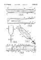
- FIG. 3is a side view of the liner folded flat
- FIG. 4is a cross sectional view taken along line 4--4 of FIG. 3;
- FIG. 5is a cross sectional view taken along line 5--5 of FIG. 3;
- FIG. 6is a cross sectional view taken along line 6--6 of FIG. 3;
- FIG. 7is a cross sectional view taken along line 7--7 of FIG. 3;
- FIG. 8is a plan view of a roll of liners illustrating the liners connected in end-to-end relation with a perforated line separating adjacent bags;
- FIG. 9is a perspective view illustrating a liner according to the first embodiment of the invention received within a cylindrical container
- FIG. 10is a partial perspective view of a second embodiment of a liner of this invention.
- FIG. 11is a side view of the liner of FIG. 9;
- FIG. 12is a cross sectional view taken along line 12--12 of FIG. 11;
- FIG. 13is a cross sectional view taken along line 13--13 of FIG. 11;
- FIG. 14is a cross sectional view taken along line 14--14 of FIG. 11;
- FIG. 15is a cross sectional view taken along line 15--15 of FIG. 11;
- FIG. 16is a perspective view of an elongate blank of material used to form a plurality of liners of FIG. 10;
- FIG. 17is a plan view of a plurality of liners of FIG. 10 formed on the elongate blank of FIG. 16.
- FIG. 1illustrates a form fit liner 10 for a container 12 and having a reduced cross-sectional area lower portion 14 received within the container 12 and an upper portion 16, having a greater perimeter and cross sectional area than that of the lower portion 14.
- the upper portion 16extends out of the container 12 and is constructed to protect the container 12 from any splashing or sloshing of the contents of the liner 10 as it is being filled or emptied.
- the upper portion 16 of the liner 10may be folded down over flaps 18 on the container or over a portion of the sidewall 20 of the container 12, if no flaps 18 are present, to protect the container 12 as it is being filled or emptied.
- the upper portion 16may remain extended above the container 12 to surround a fill tube 22 through which flowable material is discharged into the container 12 to isolate the container 12 from its contents as it is being filled and/or emptied.
- the container 12may be generally cubical with square or rectangular sidewalls 20 (FIG. 1) or it may be a cylindrical container 12' (FIG. 9) with a circular side wall 21.
- the containers 12 and 12'may be made of various materials including but not limited to plastic, card board, and the like, and may be used to ship or store hot or cold liquids including soups and various sauces as well as ice cream and other frozen or semi-frozen products. With some products an insulated container is desirable to reduce melting of the product, such as when used with ice cream.
- These containersmay have a significant wall thickness, typically on the order of 11/2 inches thick, providing a significant difference between the interior and exterior perimeter or cross-sectional areas of the container 12.
- a liner 10is generally complimentary shaped to an insulated container 12 having four rectilinear sidewalls 20 and a bottom wall 24 and preferably four flaps 18 which may be folded to close the upper end of the container 12.
- the liner 10is desirably circumferentially continuous, is preferably formed from a seamless tubular blank 26 and has an open upper end 30, four generally rectilinear sidewalls 32 and a bottom wall 34 closing the lower end and interconnecting the sidewalls 32.
- Each sidewall 32has an upper edge 36, lower edge 38 and a pair of generally opposed side edges 40.
- Each side edge 40is defined as the juncture between adjacent sidewalls 32.
- the liners 10are peferably formed of a material impervious to liquids and to the contents of the container 12 to prevent leakage and to prevent contaminants from entering the contents of the liner 10.
- the liners 10may be made from a plastic film such as polyethylene or polypropylene plastic films with a thickness in the range of about 1-10 mil. per layer.
- the bottom wall 34is preferably integrally formed with the sidewalls 32.
- the blank 26 forming the liner 10is preferably folded flat as shown in FIGS. 3 and 4 has a pair of gusseted panels 42, 44 received between a pair of overlying, flat panels 46, 48.
- all of the panels 42-48are then heat sealed together along a generally straight line 50 adjacent the lower edge of the blank 26 to seal the lower end of the liner 10 as best shown in FIGS. 3 and 6.
- each overlying flat panel 46, 48is heat sealed to its adjacent gusseted panels 42, 44 along the canted lines 52 shown in FIGS.
- the bottom wall 34has a generally rectangular configuration which is complementarily shaped to the interior of the bottom wall 24 of the container 12.
- an insulating plate 54or an insulating layer of material having low thermal conductivity, such as Teflon, is disposed within each gusseted panel 42, 44 when the heat seals 52 are formed.
- the liner 10is heat sealed along lines 56 as best shown in FIGS. 3 and 5, to connect each flat panel 46, 48 to its adjacent gusseted panels 42, 44 at a location spaced inboard of and generally parallel to each juncture or side edge 40 between the flat panels 46, 48 and gusseted panels 42, 44.
- These heat seal lines 56may be formed at the same time that the canted lines 52 of the bottom wall 34 are formed.
- a transitional heat seal portion 60extends from the heat seal lines 56 to the side edges 40 of the sidewalls 32 of the liner 10 and defines an enclosure 62 isolated from the interior of the liner 10 between the heat seal lines 56 and the side edge 40 which is excess material and may be removed if desired.
- the liners 10are formed on an elongate web 64 of material providing a generally continuous roll of liners 10 with adjacent liners 10 connected in end to end relation separated by a perforated line 66 defining the upper edge 36 of the sidewalls 32 and along which individual liners 10 may be removed or separated from the web 64 or roll of liners 10.
- a so-called bottom gusseted liner 100has a reduced perimeter or cross sectional area lower portion 102 constructed to be received within a container 12 and an increased or full perimeter or cross-sectional area upper portion 104 extending exteriorily of the container 12 to protect the container 12 as it is being filled or emptied.
- FIGS. 10-15in a second embodiment of the invention a so-called bottom gusseted liner 100 has a reduced perimeter or cross sectional area lower portion 102 constructed to be received within a container 12 and an increased or full perimeter or cross-sectional area upper portion 104 extending exteriorily of the container 12 to protect the container 12 as it is being filled or emptied.
- one method of forming the gusseted bottom of this liner 100is by folding an elongate, rectangular blank 106 of material in half along a line 107 and reverse folding it along a pair of generally parallel, spaced apart lines 108, 110 to provide a gusseted panel 114 received between a pair of overlying flat panels 116, 118.
- Each flat panel 116, 118has an upper edge 120, lower edge 108 or 110 and a pair of generally opposed side edges 124.
- the flat panels 116, 118are heat sealed along canted lines 126 to its adjacent gusseted panel 114 without heat sealing the gusseted panel 114 to itself such as by disposing an isolating plate 54 within the gusset panel 114 as previously described. As shown in FIG. 11 and 15, the flat panels 116, 118 are heat sealed along canted lines 126 to its adjacent gusseted panel 114 without heat sealing the gusseted panel 114 to itself such as by disposing an isolating plate 54 within the gusset panel 114 as previously described. As shown in FIG.
- the overlying flat panels 116, 118are heat sealed together along a line 130 spaced from and parallel to the side edges 124 and extending from at least the point of intersection with the canted lines 126 up towards the upper portion 104 of the liner 100 and terminating at a transitional heat seal 132 canted at an acute included angle relative to the heat seal line 130 and extending to the side edges 124 below the upper edge 120 of the flat panels 116, 118.
- the overlying flat panels 116, 118are heat sealed together along their side edges 124 from the upper edge 120 to at least the transitional heat seal line 132 and preferably are heat sealed along their side edges 124 along the entire length of the liner 100.
- the heat seal lines 130 spaced from the side edges 124may extend to the lower edge 108 or 110 or bottom wall 112 of the liner 100.
- the bottom wall 112is generally rectangular and interconnects four generally rectangular sidewalls 134 with only a pair of wasted material portions 136 extending from opposed sidewalls 134, generally midway within each of the opposed sidewalls 134 to form the reduced perimeter or cross-sectional area lower portion 102 of the liner 100. As shown in FIGS.
- a plurality of these bottom gusseted liners 100may be formed from an elongate web 138 of material gusset folded and sealed as described above and interconnected in side by side relation with a perforate line 140 formed between adjacent liners 100 to facilitate separating a liner 100 from the web 138.
- the form fit liners 10, 100provide a reduced perimeter or cross sectional area lower portion 14, 102 constructed to be received within a container 12 and a full perimeter or cross sectional area upper portion 16, 104 extending beyond the top of the container 12 to increase the protection of the container 12 from splashing or sloshing of the contents as the container 12 is being filled or emptied. Further, when used with insulated containers 12 having a significant wall thickness, and especially with insulated containers 12 having upper flaps 18, as shown in FIG. 1, the upper portion of the liners 10, 100 can be sufficiently large to be folded over the flaps 18 if desired.
- the upper portion of the liners 10, 100can be made large enough to be folded over a 3 inch wall thickness if flaps 18 are present on the container 12 while the lower portion 14, 102 is small enough to easily form fit within the container 12.
- These liners 10, 100may be formed on a continuous roll to facilitate manufacture, shipment, handling, dispensing and use of the liners 10, 100 and are form fit to their associated container 12 to facilitate inserting the liners 10, 100 within the container 12 and to reduce snagging or folding of the liners 10, 100 within the container 12 to improve their strength and reliability in use.
Landscapes
- Engineering & Computer Science (AREA)
- Mechanical Engineering (AREA)
- Bag Frames (AREA)
- Packages (AREA)
Abstract
Description
Claims (11)
Priority Applications (1)
| Application Number | Priority Date | Filing Date | Title |
|---|---|---|---|
| US09/003,621US5944251A (en) | 1998-01-07 | 1998-01-07 | Form fit container liner |
Applications Claiming Priority (1)
| Application Number | Priority Date | Filing Date | Title |
|---|---|---|---|
| US09/003,621US5944251A (en) | 1998-01-07 | 1998-01-07 | Form fit container liner |
Publications (1)
| Publication Number | Publication Date |
|---|---|
| US5944251Atrue US5944251A (en) | 1999-08-31 |
Family
ID=21706745
Family Applications (1)
| Application Number | Title | Priority Date | Filing Date |
|---|---|---|---|
| US09/003,621Expired - Fee RelatedUS5944251A (en) | 1998-01-07 | 1998-01-07 | Form fit container liner |
Country Status (1)
| Country | Link |
|---|---|
| US (1) | US5944251A (en) |
Cited By (23)
| Publication number | Priority date | Publication date | Assignee | Title |
|---|---|---|---|---|
| US6105821A (en)* | 1997-11-10 | 2000-08-22 | Gr Advanced Materials Ltd | Dispensing container for highly viscous liquids |
| US6151910A (en)* | 1999-11-09 | 2000-11-28 | Hazen; Steven R. | Kit for converting used buckets into coolers |
| US6257764B1 (en)* | 1996-04-16 | 2001-07-10 | Gary W. Lantz | Insulated shipping container, method of making, and article and machine used in making |
| US6305600B1 (en) | 1996-07-18 | 2001-10-23 | Climax Manufacturing Co. | Carton having a prefolded interior paper lining and a method of preparing a carton with a prefolded interior paper lining |
| US6341895B1 (en)* | 1998-12-16 | 2002-01-29 | Kanari Tani | Collapsible container with corrugated edge structure |
| US20030161554A1 (en)* | 2002-02-22 | 2003-08-28 | Patridge Clifford H. | Trash bags with narrowing seals to facilitate gripping |
| US20040013325A1 (en)* | 2002-07-22 | 2004-01-22 | Gavin Cook | Bag for flowable materials |
| US20040253399A1 (en)* | 2002-08-23 | 2004-12-16 | M&Q Plastic Products, Inc. | Cook and chill casing |
| US20060285775A1 (en)* | 2003-09-26 | 2006-12-21 | Takashi Fukuizumi | Long packaging material for manufacturing pouch |
| US7163120B1 (en) | 2000-01-27 | 2007-01-16 | M&Q Plastic Products, Inc. | Contour fit pan liner for a food service pan |
| US20070289262A1 (en)* | 2004-07-16 | 2007-12-20 | Uwe Koehn | Method and Device for Producing and Filling Sacks |
| US20080310768A1 (en)* | 2007-05-04 | 2008-12-18 | Millipore Corporation | Disposable processing bag with alignment feature |
| US20090108019A1 (en)* | 2007-10-30 | 2009-04-30 | Gino Kronfle | Ice cream packaging |
| US20100001055A1 (en)* | 2008-07-07 | 2010-01-07 | Watterson Billy J | Recycling kit and method |
| US20100224634A1 (en)* | 2009-03-04 | 2010-09-09 | Mays-Hornung Suzanne S | Liner for trash container |
| US20120170876A1 (en)* | 2009-08-26 | 2012-07-05 | Hosokawa Yoko Co., Ltd. | Gusset bag, spout-attached gusset bag, and method of manufacturing the same |
| US20130068770A1 (en)* | 2009-03-04 | 2013-03-21 | Suzanne S. Mays-Hornung | Liner for trash container |
| WO2013163180A1 (en)* | 2012-04-23 | 2013-10-31 | International Paper Company | Bulk container with bag liner secured in place |
| US8777001B1 (en) | 2009-07-07 | 2014-07-15 | William Duffy Bennett | Oil containment bag / container for the transporting and storage of electrical transformers of all types (I.E. all pole, pad mount and underground models etc.) |
| US9038844B2 (en)* | 2010-12-21 | 2015-05-26 | Nestec S.A. | Container and pouch |
| US10343817B2 (en) | 2017-03-03 | 2019-07-09 | Steven Shafer | Food containing system and devices |
| US20190389625A1 (en)* | 2018-06-26 | 2019-12-26 | Michael DiFiori | Bucket Liner Adapted To Facilitate Use With Mixing Materials |
| US20210155366A1 (en)* | 2019-11-22 | 2021-05-27 | Graphic Packaging International, Llc | Container With Liner |
Citations (8)
| Publication number | Priority date | Publication date | Assignee | Title |
|---|---|---|---|---|
| US3381886A (en)* | 1966-07-26 | 1968-05-07 | Goglio Luigi | Heat sealable bags |
| US3739977A (en)* | 1971-06-22 | 1973-06-19 | J Shapiro | Plastic market bag |
| US4171764A (en)* | 1976-04-07 | 1979-10-23 | Hoechst Aktiengesellschaft | Can lining bag of flexible plastic film |
| US4512136A (en)* | 1982-08-23 | 1985-04-23 | Trinity Associates, A Partnership Of The State Of Pennsylvania | Fitment attachment methods in horizontal form/fill/seal machines |
| US4759642A (en)* | 1986-08-11 | 1988-07-26 | Minigrip, Inc. | Reclosable bag especially suitable for cereal packaging, and method |
| US5148940A (en)* | 1991-04-03 | 1992-09-22 | Microtek Medical, Inc. | Apparatus and method for disposing of infectious medical waste |
| JPH06255657A (en)* | 1993-03-01 | 1994-09-13 | Oshio Sangyo Kk | Self-sustainable square bag and production thereof |
| US5425468A (en)* | 1993-02-26 | 1995-06-20 | Birkel; Dianne B. | Multi-purpose secretion receptacle |
- 1998
- 1998-01-07USUS09/003,621patent/US5944251A/ennot_activeExpired - Fee Related
Patent Citations (8)
| Publication number | Priority date | Publication date | Assignee | Title |
|---|---|---|---|---|
| US3381886A (en)* | 1966-07-26 | 1968-05-07 | Goglio Luigi | Heat sealable bags |
| US3739977A (en)* | 1971-06-22 | 1973-06-19 | J Shapiro | Plastic market bag |
| US4171764A (en)* | 1976-04-07 | 1979-10-23 | Hoechst Aktiengesellschaft | Can lining bag of flexible plastic film |
| US4512136A (en)* | 1982-08-23 | 1985-04-23 | Trinity Associates, A Partnership Of The State Of Pennsylvania | Fitment attachment methods in horizontal form/fill/seal machines |
| US4759642A (en)* | 1986-08-11 | 1988-07-26 | Minigrip, Inc. | Reclosable bag especially suitable for cereal packaging, and method |
| US5148940A (en)* | 1991-04-03 | 1992-09-22 | Microtek Medical, Inc. | Apparatus and method for disposing of infectious medical waste |
| US5425468A (en)* | 1993-02-26 | 1995-06-20 | Birkel; Dianne B. | Multi-purpose secretion receptacle |
| JPH06255657A (en)* | 1993-03-01 | 1994-09-13 | Oshio Sangyo Kk | Self-sustainable square bag and production thereof |
Cited By (39)
| Publication number | Priority date | Publication date | Assignee | Title |
|---|---|---|---|---|
| US6257764B1 (en)* | 1996-04-16 | 2001-07-10 | Gary W. Lantz | Insulated shipping container, method of making, and article and machine used in making |
| US6305600B1 (en) | 1996-07-18 | 2001-10-23 | Climax Manufacturing Co. | Carton having a prefolded interior paper lining and a method of preparing a carton with a prefolded interior paper lining |
| US6105821A (en)* | 1997-11-10 | 2000-08-22 | Gr Advanced Materials Ltd | Dispensing container for highly viscous liquids |
| US6341895B1 (en)* | 1998-12-16 | 2002-01-29 | Kanari Tani | Collapsible container with corrugated edge structure |
| US6151910A (en)* | 1999-11-09 | 2000-11-28 | Hazen; Steven R. | Kit for converting used buckets into coolers |
| US9307861B2 (en) | 2000-01-27 | 2016-04-12 | M & Q Ip Leasing, Llc | Contour fit pan liner for a food service pan |
| US7163120B1 (en) | 2000-01-27 | 2007-01-16 | M&Q Plastic Products, Inc. | Contour fit pan liner for a food service pan |
| US6966697B2 (en)* | 2002-02-22 | 2005-11-22 | Pactiv Corporation | Trash bags with narrowing seals to facilitate gripping |
| US20060030469A1 (en)* | 2002-02-22 | 2006-02-09 | Pactiv Corporation | Trash bags with narrowing seals to facilitate gripping |
| US20030161554A1 (en)* | 2002-02-22 | 2003-08-28 | Patridge Clifford H. | Trash bags with narrowing seals to facilitate gripping |
| US7344309B2 (en) | 2002-02-22 | 2008-03-18 | Pactiv Corporation | Trash bags with narrowing seals to facilitate gripping |
| US20080214375A1 (en)* | 2002-02-22 | 2008-09-04 | Patridge Clifford H | Trash Bags With Narrowing Seals To Facilitate Gripping |
| US20040013325A1 (en)* | 2002-07-22 | 2004-01-22 | Gavin Cook | Bag for flowable materials |
| US20040253399A1 (en)* | 2002-08-23 | 2004-12-16 | M&Q Plastic Products, Inc. | Cook and chill casing |
| US20060285775A1 (en)* | 2003-09-26 | 2006-12-21 | Takashi Fukuizumi | Long packaging material for manufacturing pouch |
| US7950850B2 (en)* | 2003-09-26 | 2011-05-31 | Fuji Seal International, Inc. | Long packaging material for manufacturing pouch |
| US7770362B2 (en)* | 2004-07-16 | 2010-08-10 | Windmoeller & Hoelscher Kg | Method and device for producing and filling sacks |
| US20070289262A1 (en)* | 2004-07-16 | 2007-12-20 | Uwe Koehn | Method and Device for Producing and Filling Sacks |
| US9090398B2 (en) | 2007-05-04 | 2015-07-28 | Emd Millipore Corporation | Disposable processing bag with alignment feature |
| US9999568B2 (en) | 2007-05-04 | 2018-06-19 | Emd Millipore Corporation | Disposable processing bag with alignment feature |
| US20080310768A1 (en)* | 2007-05-04 | 2008-12-18 | Millipore Corporation | Disposable processing bag with alignment feature |
| US9272840B2 (en) | 2007-05-04 | 2016-03-01 | Emd Millipore Corporation | Disposable processing bag with alignment feature |
| US9187240B2 (en) | 2007-05-04 | 2015-11-17 | Emd Millipore Corporation | Disposable processing bag with alignment feature |
| US20090108019A1 (en)* | 2007-10-30 | 2009-04-30 | Gino Kronfle | Ice cream packaging |
| US20100001055A1 (en)* | 2008-07-07 | 2010-01-07 | Watterson Billy J | Recycling kit and method |
| US20130068770A1 (en)* | 2009-03-04 | 2013-03-21 | Suzanne S. Mays-Hornung | Liner for trash container |
| US20100224634A1 (en)* | 2009-03-04 | 2010-09-09 | Mays-Hornung Suzanne S | Liner for trash container |
| US8777001B1 (en) | 2009-07-07 | 2014-07-15 | William Duffy Bennett | Oil containment bag / container for the transporting and storage of electrical transformers of all types (I.E. all pole, pad mount and underground models etc.) |
| US9487331B2 (en) | 2009-07-07 | 2016-11-08 | Abg Bag, Inc. | Oil containment bag/container for the transporting and storage of electrical transformers of all types (i.e. all pole, pad mount and underground models etc.) |
| US9630759B2 (en)* | 2009-08-26 | 2017-04-25 | Hosokawa Yoko Co., Ltd. | Gusset bag, spout-attached gusset bag, and method of manufacturing the same |
| US20120170876A1 (en)* | 2009-08-26 | 2012-07-05 | Hosokawa Yoko Co., Ltd. | Gusset bag, spout-attached gusset bag, and method of manufacturing the same |
| US9038844B2 (en)* | 2010-12-21 | 2015-05-26 | Nestec S.A. | Container and pouch |
| US9409690B2 (en) | 2010-12-21 | 2016-08-09 | Nestec S.A. | Container and pouch |
| WO2013163180A1 (en)* | 2012-04-23 | 2013-10-31 | International Paper Company | Bulk container with bag liner secured in place |
| US8998070B2 (en) | 2012-04-23 | 2015-04-07 | International Paper Company | Bulk container with bag liner secured in place |
| US10343817B2 (en) | 2017-03-03 | 2019-07-09 | Steven Shafer | Food containing system and devices |
| US20190389625A1 (en)* | 2018-06-26 | 2019-12-26 | Michael DiFiori | Bucket Liner Adapted To Facilitate Use With Mixing Materials |
| US20210155366A1 (en)* | 2019-11-22 | 2021-05-27 | Graphic Packaging International, Llc | Container With Liner |
| US11603231B2 (en)* | 2019-11-22 | 2023-03-14 | Graphic Packaging International, Llc | Container with liner |
Similar Documents
| Publication | Publication Date | Title |
|---|---|---|
| US5944251A (en) | Form fit container liner | |
| US5865541A (en) | Bulk container liner and method | |
| US6371646B1 (en) | Bulk bag with multiple ply walls and a method of forming it from tubular blanks | |
| US5060803A (en) | Gussetted flexible package with tear notch to form pour spout | |
| KR100518921B1 (en) | Flexible container having flat walls | |
| EP0389257B1 (en) | Flexible pouch with reinforcement to facilitate pouring | |
| US6471402B1 (en) | Formed stacking element integral with plastic storage bags | |
| US5810478A (en) | Bulk bag with lift straps and exterior liner | |
| US4865203A (en) | Sealed paper container | |
| CA1238027A (en) | Denesting paperboard container | |
| CA2032005A1 (en) | Packing unit of flexible material in the form of a sack or bag | |
| US7980410B2 (en) | Foldable bag and combination of a container and a bag and method for the use of this combination | |
| US3561669A (en) | Composite leakproof carton | |
| US6325231B1 (en) | Container for foodstuffs | |
| US3450331A (en) | Packaging material | |
| US5758973A (en) | Bulk bag with reinforced lift straps | |
| AU748162B2 (en) | Stabilized, cubic, flexible container | |
| US4778053A (en) | Packaging container with attached drinking straw | |
| US8992085B2 (en) | Self-supporting storage bag with resealable pour spout | |
| US20120145706A1 (en) | Gusseted flexible package with enlarged mouth | |
| JP3634576B2 (en) | Packaging bag with dispensing function | |
| GB2356854A (en) | Dual chamber flexible container | |
| EP0864508B1 (en) | Container of flexible material, particularly for liquid, viscous or granular products | |
| JPH04503044A (en) | upright storage bag | |
| JP3327176B2 (en) | Packaging bag with spout |
Legal Events
| Date | Code | Title | Description |
|---|---|---|---|
| AS | Assignment | Owner name:CUSTOM PACKAGING SYSTEMS, INC., MICHIGAN Free format text:ASSIGNMENT OF ASSIGNORS INTEREST;ASSIGNOR:LAFLEUR, LEE;REEL/FRAME:008957/0190 Effective date:19971210 | |
| AS | Assignment | Owner name:SCHOLLE CUSTOM PACKAGING, INC., MICHIGAN Free format text:ASSIGNMENT OF ASSIGNORS INTEREST;ASSIGNOR:CUSTOM PACKAGING SYSTEMS, INC.;REEL/FRAME:012025/0580 Effective date:20010710 | |
| FEPP | Fee payment procedure | Free format text:PAYOR NUMBER ASSIGNED (ORIGINAL EVENT CODE: ASPN); ENTITY STATUS OF PATENT OWNER: LARGE ENTITY | |
| FEPP | Fee payment procedure | Free format text:PAT HOLDER NO LONGER CLAIMS SMALL ENTITY STATUS, ENTITY STATUS SET TO UNDISCOUNTED (ORIGINAL EVENT CODE: STOL); ENTITY STATUS OF PATENT OWNER: LARGE ENTITY | |
| REFU | Refund | Free format text:REFUND - SURCHARGE, PETITION TO ACCEPT PYMT AFTER EXP, UNINTENTIONAL (ORIGINAL EVENT CODE: R2551); ENTITY STATUS OF PATENT OWNER: LARGE ENTITY | |
| FPAY | Fee payment | Year of fee payment:4 | |
| FPAY | Fee payment | Year of fee payment:8 | |
| REMI | Maintenance fee reminder mailed | ||
| LAPS | Lapse for failure to pay maintenance fees | ||
| STCH | Information on status: patent discontinuation | Free format text:PATENT EXPIRED DUE TO NONPAYMENT OF MAINTENANCE FEES UNDER 37 CFR 1.362 | |
| FP | Lapsed due to failure to pay maintenance fee | Effective date:20110831 |