US5943462A - Fiber optic stub assembly having a water resistant barrier and method for manufacturing the same - Google Patents
Fiber optic stub assembly having a water resistant barrier and method for manufacturing the sameDownload PDFInfo
- Publication number
- US5943462A US5943462AUS08/968,294US96829497AUS5943462AUS 5943462 AUS5943462 AUS 5943462AUS 96829497 AUS96829497 AUS 96829497AUS 5943462 AUS5943462 AUS 5943462A
- Authority
- US
- United States
- Prior art keywords
- fiber optic
- fibers
- optic cable
- shrink tubing
- cable assembly
- Prior art date
- Legal status (The legal status is an assumption and is not a legal conclusion. Google has not performed a legal analysis and makes no representation as to the accuracy of the status listed.)
- Expired - Lifetime
Links
- 239000000835fiberSubstances0.000titleclaimsabstractdescription150
- XLYOFNOQVPJJNP-UHFFFAOYSA-NwaterSubstancesOXLYOFNOQVPJJNP-UHFFFAOYSA-N0.000titleclaimsabstractdescription38
- 230000004888barrier functionEffects0.000titleclaimsabstractdescription35
- 238000000034methodMethods0.000titleclaimsdescription35
- 238000004519manufacturing processMethods0.000titledescription14
- 238000000576coating methodMethods0.000claimsdescription4
- 238000002788crimpingMethods0.000claimsdescription4
- 230000005693optoelectronicsEffects0.000abstractdescription14
- 230000008901benefitEffects0.000description8
- 230000003287optical effectEffects0.000description6
- 239000004593EpoxySubstances0.000description5
- 239000013307optical fiberSubstances0.000description5
- 230000000712assemblyEffects0.000description4
- 238000000429assemblyMethods0.000description4
- 239000000463materialSubstances0.000description4
- 239000000428dustSubstances0.000description3
- 230000007613environmental effectEffects0.000description3
- 238000012986modificationMethods0.000description3
- 230000004048modificationEffects0.000description3
- 230000008569processEffects0.000description3
- 238000007789sealingMethods0.000description3
- 239000011248coating agentSubstances0.000description2
- 238000009434installationMethods0.000description2
- 230000007246mechanismEffects0.000description2
- 239000004760aramidSubstances0.000description1
- 229920003235aromatic polyamidePolymers0.000description1
- 150000001875compoundsChemical class0.000description1
- 238000010276constructionMethods0.000description1
- 239000003989dielectric materialSubstances0.000description1
- 230000003292diminished effectEffects0.000description1
- 230000003467diminishing effectEffects0.000description1
- 229920001971elastomerPolymers0.000description1
- 239000000945fillerSubstances0.000description1
- 239000011521glassSubstances0.000description1
- 238000010438heat treatmentMethods0.000description1
- 238000003780insertionMethods0.000description1
- 230000037431insertionEffects0.000description1
- 238000012966insertion methodMethods0.000description1
- 238000011900installation processMethods0.000description1
- 230000002452interceptive effectEffects0.000description1
- 239000007788liquidSubstances0.000description1
- 239000011159matrix materialSubstances0.000description1
- 239000002184metalSubstances0.000description1
- 239000000203mixtureSubstances0.000description1
- 239000004033plasticSubstances0.000description1
- 238000004382pottingMethods0.000description1
- 229920002379silicone rubberPolymers0.000description1
Images


Classifications
- G—PHYSICS
- G02—OPTICS
- G02B—OPTICAL ELEMENTS, SYSTEMS OR APPARATUS
- G02B6/00—Light guides; Structural details of arrangements comprising light guides and other optical elements, e.g. couplings
- G02B6/44—Mechanical structures for providing tensile strength and external protection for fibres, e.g. optical transmission cables
- G02B6/4401—Optical cables
- G02B6/4415—Cables for special applications
- G02B6/4427—Pressure resistant cables, e.g. undersea cables
- G02B6/4428—Penetrator systems in pressure-resistant devices
- G—PHYSICS
- G02—OPTICS
- G02B—OPTICAL ELEMENTS, SYSTEMS OR APPARATUS
- G02B6/00—Light guides; Structural details of arrangements comprising light guides and other optical elements, e.g. couplings
- G02B6/24—Coupling light guides
- G02B6/36—Mechanical coupling means
- G02B6/38—Mechanical coupling means having fibre to fibre mating means
- G02B6/3807—Dismountable connectors, i.e. comprising plugs
- G02B6/3887—Anchoring optical cables to connector housings, e.g. strain relief features
- G02B6/38875—Protection from bending or twisting
- G—PHYSICS
- G02—OPTICS
- G02B—OPTICAL ELEMENTS, SYSTEMS OR APPARATUS
- G02B6/00—Light guides; Structural details of arrangements comprising light guides and other optical elements, e.g. couplings
- G02B6/24—Coupling light guides
- G02B6/36—Mechanical coupling means
- G02B6/38—Mechanical coupling means having fibre to fibre mating means
- G02B6/3807—Dismountable connectors, i.e. comprising plugs
- G02B6/3887—Anchoring optical cables to connector housings, e.g. strain relief features
- G02B6/3889—Anchoring optical cables to connector housings, e.g. strain relief features using encapsulation for protection, e.g. adhesive, molding or casting resin
- G—PHYSICS
- G02—OPTICS
- G02B—OPTICAL ELEMENTS, SYSTEMS OR APPARATUS
- G02B6/00—Light guides; Structural details of arrangements comprising light guides and other optical elements, e.g. couplings
- G02B6/24—Coupling light guides
- G02B6/42—Coupling light guides with opto-electronic elements
- G02B6/4201—Packages, e.g. shape, construction, internal or external details
- G02B6/4204—Packages, e.g. shape, construction, internal or external details the coupling comprising intermediate optical elements, e.g. lenses, holograms
- G02B6/421—Packages, e.g. shape, construction, internal or external details the coupling comprising intermediate optical elements, e.g. lenses, holograms the intermediate optical component consisting of a short length of fibre, e.g. fibre stub
Definitions
- the present inventiongenerally relates to an optical cable fitting assembly. More specifically, the present invention relates to an optical cable fitting assembly in which fiber optic cable is carried to various fiber optic or optoelectronic equipment. The present invention further provides a method for manufacturing a fiber optic cable assembly.
- Optical cablesinclude cables having at least one optical fiber of glass or other transmissive dielectric material.
- Fiber optic fitting assembliesare generally known for use in interconnecting optical cables to optoelectronic equipment. Problems may often occur during the manufacture, termination and installation of the fiber optic fitting assemblies.
- the optical fibers, when stripped from the cable jacket,are extremely fragile making it difficult to work with the fiber optic cable when assembling fittings around the end of the cable.
- the optical fibersshould not be exposed to harmful environmental conditions such as moisture, dust and dirt. Exposure to these environmental conditions may result in poor optical performance and diminished service life.
- the present inventionprovides a fiber optic stub cable assembly for use with optoelectronic equipment. Moreover, the present invention provides a method for manufacturing fiber optic stub cable assemblies.
- a fiber optic stub cable assemblyincludes an elongated housing, a cap, water resistant barrier(s) and fiber optic cable.
- the elongated housinghas a front end, a back end and an axial bore extending between the front end and the back end.
- the capis fitted into the back end of the housing.
- a fiber optic cableis contained within a cable jacket and having fibers protruding therefrom, the fibers having a mediate span and a rigid sleeve thereon wherein the fiber optic cable is constructed and arranged within the cap and the elongated housing.
- a first water resistant barrieris positioned substantially surrounding the rigid sleeve and includes a shrink tubing that is disposed around the fiber optic cable.
- the rigid sleeveis a strain relief secured to the fiber optic cable.
- a grommetis within the intermediate stepped portion of the axial bore.
- a second water resistant barrieris positioned adjacent the rigid sleeve on an opposed side of the rigid sleeve to the first water resistant barrier.
- a buffer tubingis disposed around the fibers, and the shrink tubing is positioned within the grommet.
- a buffer tubingis placed over the fibers, a spiral wrap is positioned around the buffer tubing, and a shrink tubing is disposed around the spiral wrap wherein the buffer tubing, spiral wrap and shrink tubing form a second water resistant barrier.
- a grommetis positioned within the intermediate portion, and a shrink tubing is disposed around the fibers and is positioned within the grommet.
- the front end of the housingis connectable to an optoelectronic system.
- a method for assembling a fiber optic stub fittingcomprises the steps of: providing a fiber optic cable so that fibers extend beyond an end of a cable jacket; providing a cap; providing a rigid sleeve; inserting the fibers through the cap and the rigid sleeve; providing a first shrink tubing disposed around a first portion of the fibers, the cable jacket and the rigid sleeve; providing an optic stub housing; and inserting the fibers through the optic stub housing, creating a water resistant barrier(s) within the optic stub housing.
- the methodincludes providing a grommet within the optic stub housing, and positioning the second shrink tubing within the grommet.
- the methodincludes providing a second shrink tubing disposed around a second portion of the fibers.
- the methodincludes positioning the second shrink tubing within a grommet and compressing the grommet within the optic stub housing.
- the methodincludes inserting the cap within the optic stub housing.
- the methodincludes crimping the plurality of fibers and the cable jacket before securing the first shrink tubing.
- the methodincludes positioning an inner crimp sleeve around the fibers and under the cable strength members, positioning an outer crimp sleeve over the cable strength members and the fibers, and crimping the inner crimp sleeve, the outer crimp sleeve, the stripped fibers and the cable strength members.
- the methodincludes placing the secondary buffer tubing over each of the fibers, and positioning spiral wrap around the buffer tubing.
- Another advantage of the present inventionis to provide a fiber optic cable assembly and a method for manufacturing the same that inhibits or prevents moisture from entering into the fiber optic cable assembly and the optoelectronic system.
- Another advantage of the present inventionis to provide a fiber optic cable assembly and a method for manufacturing the same that provides bend relief to the optical fibers which then project from the elongated housing.
- Yet another advantage of the present inventionis to provide a fiber optic cable assembly and method for manufacturing the same that eliminates a plug structure to encapsulate the cable sheath, mediate span of fibers and flexible buffer tubes with a potting compound thereby reducing the manufacturing time and cost.
- a still further advantage of the present inventionis to provide a fiber optic cable assembly and a method for manufacturing the same that reduces damage caused by rotation of the fiber optic cable during assembly and installation.
- an advantage of the present inventionis to provide a fiber optic cable assembly and a method for manufacturing the same that reduces damage to the optoelectronic equipment during the connection of the fiber optic cable by providing connectable features that have stopping mechanisms.
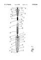
- FIG. 1is a sectional view of an embodiment of a fiber optic stub assembly of the present invention.
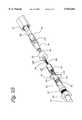
- FIG. 2Ais a perspective view of an embodiment of the fiber optic stub assembly of the present invention.
- FIG. 2Bis a perspective view of an embodiment of the fiber optic stub assembly of the present invention.
- FIG. 3is a cross-sectional view of an embodiment of the fiber optic stub assembly of the present invention.
- FIG. 4is a perspective view of an embodiment of the fiber optic stub assembly of the present invention installed in an optoelectronic system.
- FIGS. 1, 2A, and 2Billustrates an embodiment of a fiber optic cable assembly in accordance with the invention.
- the sectional view in FIG. 1shows a fiber optic stub assembly 10 in a disassembled state.
- FIGS. 2A and 2Bshow the fiber optic stub assembly 10 partially assembled.
- the assembly 10includes an optic stub illustrated as an elongated housing 12 having a front end 14, a back end 16, and an axial bore 18 extending between the front end 14 and the back end 16.
- the elongated housing 12may be generally tubular in shape.
- the elongated housing 12may be made of a rigid material, such as metal. Other materials may be used that are of a flexible nature, such as plastic.
- the assembly 10is designed to connect a fiber optic cable 20 to an optoelectronic system.
- the fiber optic cable 20may be contained within, for example, a cable jacket 22 having numerous fibers 24 protruding from the cable jacket 22.
- the fibers 24may be primary coated fibers that are furcated.
- the cable jacket 22may be stripped in order to allow the fibers 24 to extend beyond the jacket 22.
- other similar processesmay be used to achieve this end result.
- the front end 14 of the elongated housing 12is compatible with and fits into, for example, a port 30 of an optoelectronic system 32. To fit into the port 30, the front of end 14 may have threading 34 around an outer portion 38 of the housing 12.
- the threading 34may be extended from a point at the front end 14 and a predetermined length of the outer portion 38.
- the front end 14 of the housing 12guides the primary coated fibers 24 into the port 30.
- the outer portion 38is stepped out to ensure an environmentally sealed fitting between the housing 12 and the optoelectronic system 32. This fitting is important so that the furcated fibers 24 are not damaged during the installation process.
- the axial bore 18further includes a first portion 40, a second portion 42, and an intermediate tapered portion 44 extending between the first portion 40 and the second portion 42.
- the first portion 40, the second portion 42 and the intermediate tapered portion 44are positioned along a common axis 50.
- the first portion 40extends from the front end 14 to a point 52 intermediate the length of the housing 12.
- the second portion 42extends from the back end 16 to a second point 54 intermediate the length of the housing 12.
- the intermediate tapered portion 44may be conical in shape. The conical shape provides a taper between the second portion 42 to the first portion 40.
- the first portion 40has a diameter 56 that is less than a diameter 58 of the second portion 42.
- the second portion 42is capable of receiving a cap 60.
- the cap 60has a first end 62 and a second end 64.
- An external surface 66 of the cap 60is decrementally stepped from the second end 64 to the first end 62.
- the first end 62has a diameter 68 that is less than the diameter 58 of the second portion 42 of the elongated housing 12.
- the second end 64has a diameter 72 that is larger than the diameter 58 of the second portion 42.
- the larger diameter 72provides a stopping mechanism so that the cap 60 is not inserted too far into the elongated housing 12 which may result in damage to the fiber optic cable 20 or interfering with the intermediate portion 44.
- FIG. 1shows internal threading 76 around a section of the second portion 42 of the elongated housing 12.
- the threading 76extends a predetermined length from an entry point 77 at the back end 16 to a point 78 within the second portion 42.
- the threading 76allows the cap 60 to be radially inserted into the elongated housing 12.
- Other low force insertion methodsmay be used to secure the cap 60 into the elongated housing 12.
- the cap 60may be advanced forward into the housing 12 by a more resilient manner such as by a low insertion spring attachment.
- a passageway 80extends through the cap 60 so that the fiber optic cable 20 can pass through.
- FIG. 2Billustrates an inner crimp sleeve 82 placed around a cable sub-unit 120.
- the cable sub-unit 120contains the primary coated fibers 24.
- a rear edge 83 of the inner crimp sleeve 82abuts the cable jacket sheath 22.
- Cable strength members 122are typically provided between the fiber containing sub-unit 120 and jacket sheath 22. These strength members 122 are frequently comprised of aramid yarn.
- the strain relief 84is a rigid sleeve including a strain relief having an outer crimp sleeve 85 and a load-bearing flange 87 on its forward edge.
- the outer crimp sleeve 85may then be mechanically crimped in place over the inner crimp sleeve 82 with the strength members 122 captured therebetween.
- a shrink tubing 90may then be placed around the proximal ends of the cable jacket sheath 22 and the strain relief 84.
- the shrink tubing 90is an epoxy-filled heat-shrink tubing and is secured to the cable jacket sheath 22 and substantially surrounding the strain relief 84 through a heating process.
- the load bearing flange 87protrudes beyond the shrink tubing 90, as shown in FIG. 2A.
- Other processesmay, of course, be implemented to secure the shrink tubing in place, such as light, moisture or even chemically induced processes, which are generally known to one having ordinary skill in the art.
- an epoxy lining of the shrink tubing 90creates a moisture-resistant barrier between the cable sheath 22 and the strain relief 84.
- the present inventioncontemplates creating a water impervious barrier at normally encountered ambient pressure at or near the earth's surface.
- the cable sub-unit 120protrudes beyond the forward flange 87 of the strain relief 84. A portion of the sub-unit jacket is removed leaving only a small portion of the sub-unit 120 protruding beyond the forward flange 87 as shown in FIG. 2B.
- the fibers 24are protected within each sub-unit 120.
- the sub-unit 120frequently contains a moisture-impervious gel-like matrix.
- the exposed primary coated fibers 24are cleaned to remove excess gel filler from the sub-unit 120.
- Color-coded secondary buffer coating 138is slid over each primary-coated fiber 24, resulting in buffer coated fibers 94. The buffer coating provides protection to the individual fibers 24 and enables easy identification.
- a second shrink tubing 100may then be placed over the forward end of the sub-unit jacket 120 and the secondary buffer-coated fibers 94.
- the second shrink tubing 100is, generally, epoxy-filled and is exposed to heat in order to shrink the tubing 100 around the fibers 24.
- Other alternative methods of securing the shrink tubing 100 as previously set forthmay also be implemented.
- the shrink tubing 100contracts over the fibers 24 and the secondary buffer-coated fibers 94.
- a function of the shrink tubing 100is to bond the buffer coated fibers 94 (or buffer tubing) to the sub-unit jacket 120 and provide support and bend relief to the primary-coated fibers 24 which run therethrough.
- the cable jacket 22 with the outer crimp sleeve 84 and the shrink tubing 90 attached theretois pulled back within the cap 60 so that an end of the forward flange 87 engages a recess 126 in the cap 60 to avoid rotation of the cable 20.
- the primary coated fibers 24are then threaded through a grommet 92.
- the grommet 92is a donut-shaped member which fits within the intermediate portion 44 of the housing 12. To this extent, the grommet 92 is a frusto-conical shaped member. In alternative embodiments, the grommet 92 may be other shapes and sizes depending on the construction of the intermediate portion 44 of the elongated housing 12.
- the grommet 92is preferably made of a rubber material but may be constructed from different materials having similar flexible characteristics.
- the fibers 24extend through the grommet 92, and a buffer tubing 94 may be placed over each individual fiber 24. A spiral wrap 96 may be wrapped around the buffer tubing 94.
- a portion of the fibers 24 having the buffer tubing 94may be wrapped with a third shrink tubing 130.
- the third shrink tubing 130extends over the second shrink tubing 100.
- the third shrink tubing 130may also be epoxy-filled and may be exposed to heat in order to shrink the tubing 130 around the fibers 24, the buffer tubing 94 and the second shrink tubing 100.
- An O-ring 102may be placed over the spiral wrap 96, and the fibers 24 are threaded into the back end 16 of the elongated housing 12 and out through the front end 14 of the elongated housing 12.
- An O-ring 111may be used to provide a further seal between the cap 60 and housing 12 to reduce the risk of moisture, dust or dirt from entering the assembly 10.
- the O-ring 111is positioned between the optic cap 60 and the housing 12.
- the threading of the fibers 24 through the elongated housing 12causes the grommet 92 to be located within the intermediate portion 44 of the housing 12.
- the cap 60is then radially inserted within the back end 16 of the housing 12.
- external threading 110is provided around the first end 62 of the cap 60 that engages with the internal threading 76 of the housing 12.
- the cap 60is screwed into the optic stub housing 12 to compress the grommet 92 against the intermediate portion 44 of the housing 12 and provide a surface-to-surface seal.
- the grommet 92functions as another water barrier to the front end 14 of the housing 12.
- the third shrink tubing 130fits snugly within a hole 112 of the grommet 92 so that a water-resistant barrier is formed.
- An O-ring 114may then be placed at the front end 14 of the housing 12.
- the O-ring 114centers the stripped fibers 94 extending beyond the front end 14 of the housing 12 within the axial bore 18.
- the O-ring 114also provides a water resistant seal at the front end 14 of the housing 12.
- the O-ring 114may be replaced by injecting epoxy or a silicon rubber in the front end 14 of the housing 12 to center the stripped fibers and to provide the water resistant seal at the front end 14 of the optic stub housing 12.
- FIG. 3illustrates the fiber optic stub cable assembly 10 in an assembled state.
- the cap 60is secured to the housing 12.
- the grommet 92is compressed against the intermediate portion 44 of the housing 12 and formed around the third heat shrink tubing 130, thus providing a water resistant barrier.
- the entire assemblymay then be attached to the closed optoelectronic system 32 by screwing the external threading 34 at the front end 14 of the housing 12 into the port 30 of the system 32 as shown in FIG. 4.
- the entire fiber optic stub assembly 10may be covered with a heat-shrink tubing (not shown).
- this inventionprovides a novel fiber optic stub cable assembly and method for manufacturing the same. It should be understood that various changes and modifications to the presently preferred embodiments described herein will be apparent to those skilled in the art. Such changes and modifications may be made without departing from the spirit and scope of the present invention and without diminishing its attendant advantages. It is, therefore, intended that such changes and modifications be covered by the appended claims.
- the present inventionmay not only provide a barrier to water, but also other liquids including water mixtures.
Landscapes
- Physics & Mathematics (AREA)
- General Physics & Mathematics (AREA)
- Optics & Photonics (AREA)
- Cable Accessories (AREA)
Abstract
Description
Claims (33)
Priority Applications (1)
| Application Number | Priority Date | Filing Date | Title |
|---|---|---|---|
| US08/968,294US5943462A (en) | 1997-11-12 | 1997-11-12 | Fiber optic stub assembly having a water resistant barrier and method for manufacturing the same |
Applications Claiming Priority (1)
| Application Number | Priority Date | Filing Date | Title |
|---|---|---|---|
| US08/968,294US5943462A (en) | 1997-11-12 | 1997-11-12 | Fiber optic stub assembly having a water resistant barrier and method for manufacturing the same |
Publications (1)
| Publication Number | Publication Date |
|---|---|
| US5943462Atrue US5943462A (en) | 1999-08-24 |
Family
ID=25514029
Family Applications (1)
| Application Number | Title | Priority Date | Filing Date |
|---|---|---|---|
| US08/968,294Expired - LifetimeUS5943462A (en) | 1997-11-12 | 1997-11-12 | Fiber optic stub assembly having a water resistant barrier and method for manufacturing the same |
Country Status (1)
| Country | Link |
|---|---|
| US (1) | US5943462A (en) |
Cited By (21)
| Publication number | Priority date | Publication date | Assignee | Title |
|---|---|---|---|---|
| US6113285A (en)* | 1998-05-26 | 2000-09-05 | Lucifer Lighting Co. | Illuminator heat dissipation system |
| US6326550B1 (en) | 2000-11-13 | 2001-12-04 | General Dynamics Advanced Technology Systems, Inc. | Cable seal |
| WO2002025344A1 (en)* | 2000-09-25 | 2002-03-28 | Schlumberger Technology B.V. | An optical feedthrough |
| US6434317B1 (en) | 2000-11-13 | 2002-08-13 | General Dynamics Advanced Technology Systems, Inc. | Pressure vessel assembly |
| US20050220434A1 (en)* | 2004-03-30 | 2005-10-06 | John Hsieh | Dust cap for fiber optic components |
| WO2007075723A3 (en)* | 2005-12-19 | 2007-08-16 | Molex Inc | Industrial optical fiber connector assembly |
| US20080013888A1 (en)* | 2006-06-30 | 2008-01-17 | Barnes Brandon A | Optical fiber transition device |
| US20090060421A1 (en)* | 2007-03-16 | 2009-03-05 | 3M Innovative Properties Company | Optical fiber cable inlet device |
| US20090097799A1 (en)* | 2007-10-16 | 2009-04-16 | Sumitomo Electric Industries, Ltd. | Optical connector |
| US20090202207A1 (en)* | 2005-08-15 | 2009-08-13 | Molex Incorporated | Industrial interconnect system incorporating transceiver module cage |
| US20100027955A1 (en)* | 2008-08-01 | 2010-02-04 | 3M Innovative Properties Company | Optical fiber cable inlet device with integral optical device |
| US20100079248A1 (en)* | 2008-09-29 | 2010-04-01 | Johannes Ian Greveling | Optical fiber connector assembly with wire-based RFID antenna |
| CN102122030A (en)* | 2010-01-08 | 2011-07-13 | Ofs飞泰尔有限责任公司 | Connector cover for outside plant applications |
| US20110175503A1 (en)* | 2008-11-14 | 2011-07-21 | Aravind Chamarti | Equipment cabinet having improved space utilization |
| US8313250B2 (en) | 2008-04-09 | 2012-11-20 | 3M Innovative Properties Company | Telecommunications cable inlet device |
| US8410909B2 (en) | 2010-07-09 | 2013-04-02 | Corning Incorporated | Cables and connector assemblies employing a furcation tube(s) for radio-frequency identification (RFID)-equipped connectors, and related systems and methods |
| US20140241676A1 (en)* | 2013-02-28 | 2014-08-28 | Matthew Wade Smith | Furcating fiber optic cables without direct coupling of optical fibers to strength members, and related assemblies and methods |
| CN104181658A (en)* | 2014-09-11 | 2014-12-03 | 成都前宏通讯有限责任公司 | Mechanical sealing locking device for elliptical hole of cable splice closure |
| US20150219868A1 (en)* | 2013-08-09 | 2015-08-06 | Seiwa Electric Mfg. Co., Ltd. | Locking devise for optical drop cable |
| US20210364715A1 (en)* | 2020-05-20 | 2021-11-25 | Commscope Technologies Llc | Active optical cable assemblies |
| US12268860B1 (en)* | 2018-08-27 | 2025-04-08 | Abiomed, Inc. | Nitinol braid processing procedure |
Citations (16)
| Publication number | Priority date | Publication date | Assignee | Title |
|---|---|---|---|---|
| US4230395A (en)* | 1975-02-05 | 1980-10-28 | Bicc Limited | Optical cables with loosely housed optical guides |
| US4616900A (en)* | 1984-04-02 | 1986-10-14 | Lockheed Corporation | Coaxial underwater electro-optical connector |
| US4666242A (en)* | 1984-06-21 | 1987-05-19 | Lockheed Corporation | Underwater electro-optical connector including cable terminal unit with electro-optical probe |
| US4932746A (en)* | 1987-06-01 | 1990-06-12 | Societa' Cavi Pirelli S.P.A. | Optical fiber cable with optical fibers in tubes unbonded to surrounding core |
| US5185844A (en)* | 1991-07-29 | 1993-02-09 | At&T Bell Laboratories | Closure for optical fiber connective arrangements and method of providing same |
| US5217808A (en)* | 1989-11-29 | 1993-06-08 | At&T Bell Laboratories | Water blocked cable portion and methods of making same |
| US5224187A (en)* | 1992-04-29 | 1993-06-29 | Scientific-Atlanta, Inc. | Fiber optic cable connectors providing strain relief |
| US5245134A (en)* | 1990-08-29 | 1993-09-14 | W. L. Gore & Associates, Inc. | Polytetrafluoroethylene multiconductor cable and process for manufacture thereof |
| US5249248A (en)* | 1991-11-27 | 1993-09-28 | At&T Bell Laboratories | Communication cable having a core wrap binder which provides water-blocking and strength properties |
| US5271081A (en)* | 1992-06-18 | 1993-12-14 | Halliburton Geophysical Services, Inc. | Apparatus and method of blocking water migration between stranded signal conduits |
| US5289556A (en)* | 1992-09-23 | 1994-02-22 | Northern Telecom Limited | Optical fiber units and optical cables |
| US5373100A (en)* | 1992-05-29 | 1994-12-13 | At&T Corp. | Communication cable having water-blocking capabilities |
| US5416874A (en)* | 1994-07-01 | 1995-05-16 | Siecor Corporation | Optical receiver stub fitting |
| US5425121A (en)* | 1994-02-02 | 1995-06-13 | Siecor Corporation | Cable assembly for use with opto-electronic equipment enclosures |
| US5567174A (en)* | 1994-06-02 | 1996-10-22 | The Ericson Manufacturing Co. | Water tight grease filled connector with strain relief |
| US5838861A (en)* | 1997-03-06 | 1998-11-17 | Newport News Shipbuilding And Dry Dock Company | Transition assembly for optical fiber |
- 1997
- 1997-11-12USUS08/968,294patent/US5943462A/ennot_activeExpired - Lifetime
Patent Citations (16)
| Publication number | Priority date | Publication date | Assignee | Title |
|---|---|---|---|---|
| US4230395A (en)* | 1975-02-05 | 1980-10-28 | Bicc Limited | Optical cables with loosely housed optical guides |
| US4616900A (en)* | 1984-04-02 | 1986-10-14 | Lockheed Corporation | Coaxial underwater electro-optical connector |
| US4666242A (en)* | 1984-06-21 | 1987-05-19 | Lockheed Corporation | Underwater electro-optical connector including cable terminal unit with electro-optical probe |
| US4932746A (en)* | 1987-06-01 | 1990-06-12 | Societa' Cavi Pirelli S.P.A. | Optical fiber cable with optical fibers in tubes unbonded to surrounding core |
| US5217808A (en)* | 1989-11-29 | 1993-06-08 | At&T Bell Laboratories | Water blocked cable portion and methods of making same |
| US5245134A (en)* | 1990-08-29 | 1993-09-14 | W. L. Gore & Associates, Inc. | Polytetrafluoroethylene multiconductor cable and process for manufacture thereof |
| US5185844A (en)* | 1991-07-29 | 1993-02-09 | At&T Bell Laboratories | Closure for optical fiber connective arrangements and method of providing same |
| US5249248A (en)* | 1991-11-27 | 1993-09-28 | At&T Bell Laboratories | Communication cable having a core wrap binder which provides water-blocking and strength properties |
| US5224187A (en)* | 1992-04-29 | 1993-06-29 | Scientific-Atlanta, Inc. | Fiber optic cable connectors providing strain relief |
| US5373100A (en)* | 1992-05-29 | 1994-12-13 | At&T Corp. | Communication cable having water-blocking capabilities |
| US5271081A (en)* | 1992-06-18 | 1993-12-14 | Halliburton Geophysical Services, Inc. | Apparatus and method of blocking water migration between stranded signal conduits |
| US5289556A (en)* | 1992-09-23 | 1994-02-22 | Northern Telecom Limited | Optical fiber units and optical cables |
| US5425121A (en)* | 1994-02-02 | 1995-06-13 | Siecor Corporation | Cable assembly for use with opto-electronic equipment enclosures |
| US5567174A (en)* | 1994-06-02 | 1996-10-22 | The Ericson Manufacturing Co. | Water tight grease filled connector with strain relief |
| US5416874A (en)* | 1994-07-01 | 1995-05-16 | Siecor Corporation | Optical receiver stub fitting |
| US5838861A (en)* | 1997-03-06 | 1998-11-17 | Newport News Shipbuilding And Dry Dock Company | Transition assembly for optical fiber |
Cited By (38)
| Publication number | Priority date | Publication date | Assignee | Title |
|---|---|---|---|---|
| US6113285A (en)* | 1998-05-26 | 2000-09-05 | Lucifer Lighting Co. | Illuminator heat dissipation system |
| US20030180025A1 (en)* | 2000-09-25 | 2003-09-25 | Fabien Cens | Optical feedthrough |
| WO2002025344A1 (en)* | 2000-09-25 | 2002-03-28 | Schlumberger Technology B.V. | An optical feedthrough |
| FR2814550A1 (en)* | 2000-09-25 | 2002-03-29 | Schlumberger Services Petrol | OPTICAL CROSSING |
| GB2383139A (en)* | 2000-09-25 | 2003-06-18 | Schlumberger Holdings | An optical feedthrough |
| GB2383139B (en)* | 2000-09-25 | 2004-06-02 | Schlumberger Holdings | Feedthrough with optic fibre sealed in protective tube |
| US6779927B2 (en)* | 2000-09-25 | 2004-08-24 | Schlumberger Technology Corporation | Feedthrough with optic fiber sealed in protective tube and optical measurement apparatus using the same |
| US6434317B1 (en) | 2000-11-13 | 2002-08-13 | General Dynamics Advanced Technology Systems, Inc. | Pressure vessel assembly |
| US6326550B1 (en) | 2000-11-13 | 2001-12-04 | General Dynamics Advanced Technology Systems, Inc. | Cable seal |
| US20050220434A1 (en)* | 2004-03-30 | 2005-10-06 | John Hsieh | Dust cap for fiber optic components |
| US7164840B2 (en)* | 2004-03-30 | 2007-01-16 | Finisar Corporation | Dust cap for fiber optic components |
| US20090202207A1 (en)* | 2005-08-15 | 2009-08-13 | Molex Incorporated | Industrial interconnect system incorporating transceiver module cage |
| US9048573B2 (en) | 2005-08-15 | 2015-06-02 | Molex Incorporated | Industrial interconnect system incorporating transceiver module cage |
| WO2007075723A3 (en)* | 2005-12-19 | 2007-08-16 | Molex Inc | Industrial optical fiber connector assembly |
| US20080013888A1 (en)* | 2006-06-30 | 2008-01-17 | Barnes Brandon A | Optical fiber transition device |
| US7512308B2 (en)* | 2006-06-30 | 2009-03-31 | Corning Incorporated | Optical fiber transition device |
| US20090060421A1 (en)* | 2007-03-16 | 2009-03-05 | 3M Innovative Properties Company | Optical fiber cable inlet device |
| US20100086260A1 (en)* | 2007-03-16 | 2010-04-08 | Parikh Rutesh D | Optical fiber cable inlet device and telecommunications enclosure system |
| US7738759B2 (en) | 2007-03-16 | 2010-06-15 | 3M Innovative Properties Company | Optical fiber cable inlet device |
| US8879883B2 (en) | 2007-03-16 | 2014-11-04 | 3M Innovative Properties Company | Optical fiber cable inlet device and telecommunications enclosure system |
| US20090097799A1 (en)* | 2007-10-16 | 2009-04-16 | Sumitomo Electric Industries, Ltd. | Optical connector |
| EP2053433A1 (en)* | 2007-10-26 | 2009-04-29 | Sumitomo Electric Industries, Ltd. | Optical connector |
| US7988368B2 (en) | 2007-10-26 | 2011-08-02 | Sumitomo Electric Industries, Ltd. | Optical connector |
| US8313250B2 (en) | 2008-04-09 | 2012-11-20 | 3M Innovative Properties Company | Telecommunications cable inlet device |
| US20100027955A1 (en)* | 2008-08-01 | 2010-02-04 | 3M Innovative Properties Company | Optical fiber cable inlet device with integral optical device |
| US8184939B2 (en)* | 2008-08-01 | 2012-05-22 | 3M Innovative Properties Company | Optical fiber cable inlet device with integral optical device |
| US20100079248A1 (en)* | 2008-09-29 | 2010-04-01 | Johannes Ian Greveling | Optical fiber connector assembly with wire-based RFID antenna |
| US20110175503A1 (en)* | 2008-11-14 | 2011-07-21 | Aravind Chamarti | Equipment cabinet having improved space utilization |
| CN102122030A (en)* | 2010-01-08 | 2011-07-13 | Ofs飞泰尔有限责任公司 | Connector cover for outside plant applications |
| US8410909B2 (en) | 2010-07-09 | 2013-04-02 | Corning Incorporated | Cables and connector assemblies employing a furcation tube(s) for radio-frequency identification (RFID)-equipped connectors, and related systems and methods |
| US20140241676A1 (en)* | 2013-02-28 | 2014-08-28 | Matthew Wade Smith | Furcating fiber optic cables without direct coupling of optical fibers to strength members, and related assemblies and methods |
| US9069152B2 (en)* | 2013-02-28 | 2015-06-30 | Corning Optical Communications LLC | Furcating fiber optic cables without direct coupling of optical fibers to strength members, and related assemblies and methods |
| US20150219868A1 (en)* | 2013-08-09 | 2015-08-06 | Seiwa Electric Mfg. Co., Ltd. | Locking devise for optical drop cable |
| US9261665B2 (en)* | 2013-08-09 | 2016-02-16 | Seiwa Electric Mfg. Co., Ltd. | Locking devise for optical drop cable |
| CN104181658A (en)* | 2014-09-11 | 2014-12-03 | 成都前宏通讯有限责任公司 | Mechanical sealing locking device for elliptical hole of cable splice closure |
| US12268860B1 (en)* | 2018-08-27 | 2025-04-08 | Abiomed, Inc. | Nitinol braid processing procedure |
| US20210364715A1 (en)* | 2020-05-20 | 2021-11-25 | Commscope Technologies Llc | Active optical cable assemblies |
| US11585994B2 (en)* | 2020-05-20 | 2023-02-21 | Commscope Technologies Llc | Active optical cable assemblies |
Similar Documents
| Publication | Publication Date | Title |
|---|---|---|
| US5943462A (en) | Fiber optic stub assembly having a water resistant barrier and method for manufacturing the same | |
| EP2283390B1 (en) | Hardened fiber optic connector with connector body joined to cylindrical cable by unitary housing | |
| US10983284B2 (en) | Hardened fiber optic connector with pre-compressed spring | |
| US5465313A (en) | Optical fiber connector and method of fabricating same | |
| US10036859B2 (en) | Cable termination assembly and method for connectors | |
| JP5106235B2 (en) | Reinforced connector system including transducer | |
| KR101083472B1 (en) | Fiber optic plug | |
| CA1201314A (en) | Connector for fiber optic member | |
| US7686519B2 (en) | Hardened fiber optic housing and cable assembly | |
| AU648449B2 (en) | Hermaphroditic connector for single fiber optical cable | |
| JPS5848082B2 (en) | fiber optic connector assembly | |
| US9395500B2 (en) | Optical fiber connector and cable assembly with dual diameter crimp sleeve | |
| US5140662A (en) | Method of assembling connector and cable | |
| EP0717859B1 (en) | Plug-type connector | |
| CS49591A3 (en) | Pulling head for optical cables of a ribbon type being provided with connectors | |
| WO2009114771A1 (en) | Method of attachment of a connector to a fiber optic cable | |
| US5455880A (en) | Optical fiber cable connector assembly | |
| US7192194B2 (en) | Universal adapter for fiber optic connectors | |
| US20240369781A1 (en) | Optical fiber cable with optical connector, method for manufacturing optical fiber cable with optical connector, and optical connector | |
| JPS5936208A (en) | Optical connector plug | |
| JPH0442804Y2 (en) | ||
| JPS58190910A (en) | Optical connector | |
| JPH01237606A (en) | Ferrule for optical connector | |
| CS242586B1 (en) | Fiber optic cable connector |
Legal Events
| Date | Code | Title | Description |
|---|---|---|---|
| AS | Assignment | Owner name:SIEMENS BUSINESS COMMUNICATION SYSTEMS, INC., CALI Free format text:;ASSIGNORS:CARLETON, RONALD ROBERT;BEYDA, WILLIAM JOSEPH;SHAFFER, SHMUEL;REEL/FRAME:008802/0841 Effective date:19971028 | |
| AS | Assignment | Owner name:METHODE ELECTRONICS, INC., ILLINOIS Free format text:ASSIGNMENT OF ASSIGNORS INTEREST;ASSIGNORS:SCHOFIELD, PHILIP W.;WUESTMANN, DAVID E.;REEL/FRAME:008816/0714 Effective date:19971110 | |
| STCF | Information on status: patent grant | Free format text:PATENTED CASE | |
| AS | Assignment | Owner name:STRATOS LIGHTWAVE LLC, ILLINOIS Free format text:ASSIGNMENT OF ASSIGNORS INTEREST;ASSIGNORS:METHODE ELECTRONICS, INC.;STRATOS LIGHTWAVE LLC;REEL/FRAME:010949/0722;SIGNING DATES FROM 20000605 TO 20000621 | |
| REMI | Maintenance fee reminder mailed | ||
| FPAY | Fee payment | Year of fee payment:4 | |
| SULP | Surcharge for late payment | ||
| FPAY | Fee payment | Year of fee payment:8 | |
| AS | Assignment | Owner name:STRATOS INTERNATIONAL, INC., ILLINOIS Free format text:CHANGE OF NAME;ASSIGNOR:STRATOS LIGHTWAVE, INC.;REEL/FRAME:022542/0180 Effective date:20031121 Owner name:STRATOS LIGHTWAVE, INC., ILLINOIS Free format text:ASSIGNMENT OF ASSIGNORS INTEREST;ASSIGNOR:STRATOS LIGHTWAVE LLC;REEL/FRAME:022542/0100 Effective date:20000621 | |
| FPAY | Fee payment | Year of fee payment:12 | |
| AS | Assignment | Owner name:KEYBANK NATIONAL ASSOCIATION, AS ADMINISTRATIVE AG Free format text:INTELLECTUAL PROPERTY SECURITY AGREEMENT;ASSIGNOR:STRATOS INTERNATIONAL, LLC;REEL/FRAME:033429/0049 Effective date:20140725 |