US5943375A - Method to indicate synchronization lock of a remote station with a base station - Google Patents
Method to indicate synchronization lock of a remote station with a base stationDownload PDFInfo
- Publication number
- US5943375A US5943375AUS08/796,492US79649297AUS5943375AUS 5943375 AUS5943375 AUS 5943375AUS 79649297 AUS79649297 AUS 79649297AUS 5943375 AUS5943375 AUS 5943375A
- Authority
- US
- United States
- Prior art keywords
- remote station
- clock signal
- signal
- symbol pattern
- forming
- Prior art date
- Legal status (The legal status is an assumption and is not a legal conclusion. Google has not performed a legal analysis and makes no representation as to the accuracy of the status listed.)
- Expired - Lifetime
Links
Images


Classifications
- H—ELECTRICITY
- H04—ELECTRIC COMMUNICATION TECHNIQUE
- H04L—TRANSMISSION OF DIGITAL INFORMATION, e.g. TELEGRAPHIC COMMUNICATION
- H04L5/00—Arrangements affording multiple use of the transmission path
- H04L5/0001—Arrangements for dividing the transmission path
- H04L5/0014—Three-dimensional division
- H04L5/0016—Time-frequency-code
- H—ELECTRICITY
- H04—ELECTRIC COMMUNICATION TECHNIQUE
- H04B—TRANSMISSION
- H04B1/00—Details of transmission systems, not covered by a single one of groups H04B3/00 - H04B13/00; Details of transmission systems not characterised by the medium used for transmission
- H04B1/69—Spread spectrum techniques
- H—ELECTRICITY
- H04—ELECTRIC COMMUNICATION TECHNIQUE
- H04L—TRANSMISSION OF DIGITAL INFORMATION, e.g. TELEGRAPHIC COMMUNICATION
- H04L27/00—Modulated-carrier systems
- H04L27/26—Systems using multi-frequency codes
- H04L27/2601—Multicarrier modulation systems
- H04L27/2602—Signal structure
- H04L27/261—Details of reference signals
- H04L27/2613—Structure of the reference signals
- H—ELECTRICITY
- H04—ELECTRIC COMMUNICATION TECHNIQUE
- H04L—TRANSMISSION OF DIGITAL INFORMATION, e.g. TELEGRAPHIC COMMUNICATION
- H04L27/00—Modulated-carrier systems
- H04L27/26—Systems using multi-frequency codes
- H04L27/2601—Multicarrier modulation systems
- H04L27/2647—Arrangements specific to the receiver only
- H04L27/2655—Synchronisation arrangements
- H04L27/2657—Carrier synchronisation
- H04L27/2659—Coarse or integer frequency offset determination and synchronisation
- H—ELECTRICITY
- H04—ELECTRIC COMMUNICATION TECHNIQUE
- H04L—TRANSMISSION OF DIGITAL INFORMATION, e.g. TELEGRAPHIC COMMUNICATION
- H04L27/00—Modulated-carrier systems
- H04L27/26—Systems using multi-frequency codes
- H04L27/2601—Multicarrier modulation systems
- H04L27/2647—Arrangements specific to the receiver only
- H04L27/2655—Synchronisation arrangements
- H04L27/2657—Carrier synchronisation
- H04L27/266—Fine or fractional frequency offset determination and synchronisation
- H—ELECTRICITY
- H04—ELECTRIC COMMUNICATION TECHNIQUE
- H04L—TRANSMISSION OF DIGITAL INFORMATION, e.g. TELEGRAPHIC COMMUNICATION
- H04L27/00—Modulated-carrier systems
- H04L27/26—Systems using multi-frequency codes
- H04L27/2601—Multicarrier modulation systems
- H04L27/2647—Arrangements specific to the receiver only
- H04L27/2655—Synchronisation arrangements
- H04L27/2668—Details of algorithms
- H04L27/2673—Details of algorithms characterised by synchronisation parameters
- H04L27/2675—Pilot or known symbols
- H—ELECTRICITY
- H04—ELECTRIC COMMUNICATION TECHNIQUE
- H04L—TRANSMISSION OF DIGITAL INFORMATION, e.g. TELEGRAPHIC COMMUNICATION
- H04L5/00—Arrangements affording multiple use of the transmission path
- H04L5/003—Arrangements for allocating sub-channels of the transmission path
- H04L5/0048—Allocation of pilot signals, i.e. of signals known to the receiver
- H—ELECTRICITY
- H04—ELECTRIC COMMUNICATION TECHNIQUE
- H04W—WIRELESS COMMUNICATION NETWORKS
- H04W56/00—Synchronisation arrangements
- H04W56/0055—Synchronisation arrangements determining timing error of reception due to propagation delay
- H04W56/0065—Synchronisation arrangements determining timing error of reception due to propagation delay using measurement of signal travel time
- H04W56/007—Open loop measurement
- H04W56/0075—Open loop measurement based on arrival time vs. expected arrival time
- H04W56/0085—Open loop measurement based on arrival time vs. expected arrival time detecting a given structure in the signal
- H—ELECTRICITY
- H04—ELECTRIC COMMUNICATION TECHNIQUE
- H04W—WIRELESS COMMUNICATION NETWORKS
- H04W92/00—Interfaces specially adapted for wireless communication networks
- H04W92/04—Interfaces between hierarchically different network devices
- H04W92/10—Interfaces between hierarchically different network devices between terminal device and access point, i.e. wireless air interface
Definitions
- This inventioninvolves improvements to communications systems and methods in a wireless discrete tone communications system.
- Wireless communications systemssuch as cellular and personal communications systems, operate over limited spectral bandwidths and must make highly efficient use of the scarce bandwidth resource for providing good service to a large population of users.
- Wireless systemsconsist of cells, each of which include a base station and remote units.
- the Personal Wireless Access Network described in the Alamouti, et al patent application cited above,is an example of a successful technology for wireless service.
- the personal wireless access network (PWAN) system described in the referenced Alamouti, et al. patent applicationuses a form of the protocol known as discrete tone to provide efficient communications between a station and a plurality of remote stations.
- the user's data signalis modulated by a set of weighted discrete frequencies or tones.
- the weightsare spatial spreading codes that distribute the data signal over many discrete tones covering a broad range of frequencies.
- the weightsare complex numbers with the real component acting to modulate the amplitude of a tone while the complex component of the weight acts to modulate the phase of the same tone.
- Each tone in the weighted tone setbears different data signals.
- the stationwhere it is processed with despreading codes to recover the user's data signal.
- the received discrete tone signalsare transformed from time domain signals to frequency domain signals.
- Despreading weightsare assigned to each frequency component of the signals received by each antenna element.
- the values of the despreading weightsare combined with the received signals to obtain an optimized approximation of individual transmitted signals characterized by a particular discrete tone set and transmitting location.
- the PWAN systemhas a total of 2560 discrete tones (carriers) equally spaced in 8 MHz of available bandwidth in the range of 1850 to 1990 MHz.
- the spacing between the tonesis 3.125 KHz.
- the total set of tonesare numbered consecutively form 0 to 2559 starting from the lowest frequency tone.
- the tonesare used to carry traffic messages and overhead messages between the base station and the plurality of remote stations.
- the traffic tonesare divided into 32 traffic partitions, with each traffic channel requiring at least one traffic partition of 72 tones.
- the PWAN systemuses overhead tones to establish synchronization and to pass control information between the base station and the remote stations.
- a Common Link Channel (CLC)is used by the base to transmit control information to the Remote stations.
- a Common Access Channel (CAC)is used to transmit messages from the Remote station to the Base. There is one grouping of tones assigned to each channel. These overhead channels are used in common by all of the remote stations when they are exchanging control messages with the base station.
- Frequency Division DuplexingIn the PWAN system, Frequency Division Duplexing (FDD) is used by the base station and the remote station to transmit data and control information in both directions. Transmission from the base station to the remote station is called forward transmission and transmission from the remote station to the base station is called reverse transmission.
- the base station and each remote stationmust synchronize and conform to the timing structure and both the base station and the remote station must synchronize to a framing structure. All remote stations and base stations must be synchronized so that all remote stations transmit at the same time and then all base stations transmit at the same time.
- a remote stationinitially powers up, it acquires synchronization from the base station so that it can exchange control and traffic messages within the prescribed time format.
- the remote stationmust also acquire frequency and time synchronization for the signals so that the remote is operating at the same frequency and time as the base station.
- the PWAN wireless communications system, and other limited bandwidth communications systems,need to exploit new techniques to make the most efficient use of the scarce bandwidth resource to provide good service to a large population of users.
- a method for a wireless discrete tone communications systemfor synchronizing the remote station to the base station.
- the methodbegins with the step of generating a clock signal at the base station.
- the base stationthen derives a synchronization symbol pattern from the base station clock signal.
- the base stationspreads the synchronization symbol pattern with spreading codes that distributes the synchronization symbol pattern over a plurality of discrete tones, forming a spread signal.
- the base stationthen transmits the spread signal to the remote station.
- the remote stationgenerates a first clock signal. In accordance with the invention, it then samples the discrete tones using the remote station first clock signal, forming a first sampled signal. Then the remote station applies the first sampled signal to a matched filter bank, forming a frequency error signal. The method then adjusts a frequency of the remote station first clock signal using the frequency error signal, forming a second clock signal. Then the remote station samples the discrete tones using the remote station second clock signal, forming a second sampled signal. Then the remote station despreads the second sampled signal with despreading codes to extract the synchronization symbol pattern. Then the remote station compares the extracted synchronization symbol pattern with a reference symbol pattern at the remote station. If the comparing step is successful, then the remote station selectively processes traffic signals received from the base station using the second clock signal.
- the remote stationselectively adjusts a time offset value of the remote station second clock signal forming a third clock signal, if the comparing step is not successful.
- the remote stationsamples the discrete tones using the remote station third clock signal, forming a third sampled signal.
- the remote stationthen despreads the third sampled signal with despreading codes to form a second extraction of the synchronization symbol pattern.
- the remote stationcompares the second extraction of the synchronization symbol pattern with the reference symbol pattern at the remote station. If the step of comparing the second extraction is successful, then the remote station selectively processes traffic signals received from the base station using the third clock signal.
- the inventionhas advantageous applications in the field of wireless communications, such as cellular communications or personal communications, where bandwidth is scarce compared to the number of the users and their needs. Such applications may be effected in mobile, fixed, or minimally mobile systems. However, the invention may be advantageously applied to other, non-wireless, communications systems as well.
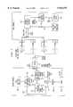
- FIG. 1is an overall architectural view of the PWAN communication system showing the base station Z and the remote station X.
- FIG. 2is a more detailed functional block diagram of the remote station X, featuring the sync block 150.
- FIG. 3is a more detailed functional block diagram of the A/D sampler and digitizer 140 in the remote station X.
- FIG. 4Ais a diagram in the frequency domain of the fast Fourier transform (FFT) frequency bins for a first, coarse measurement.
- FFTfast Fourier transform
- FIG. 4Billustrates the coarse frequency bins of FIG. 4A, in a second stage of the measurement, where the oscillator frequency is adjusted to move the FFT bin with the largest energy to the center frequency, FC.
- FIG. 4Cillustrates the fine frequency bins for a first, fine measurement.
- FIG. 4Dillustrates the fine frequency bins for a second stage of the fine frequency measurement, where the oscillator frequency is adjusted to move the FFT bin with the largest energy to the center frequency, FC.
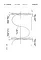
- FIG. 5Aillustrates the observation window and the sampling window for measuring the requency characteristics of the pilot tones.
- FIG. 5Billustrates the observation window and the sampling window for measuring the time characteristics of a pilot tone.
- FIG. 6is a flow diagram of a sequence of operational steps carried out by the base station and the remote station, in accordance with the invention.
- FIG. 1shows an overall functional block diagram of PWAN system, in accordance with the invention.
- the PWAN systemis a wireless discrete tone communication system.
- the inventionsynchronizes the remote station (also referred to as the remote unit) X to the base station Z for both the frequency and the timing characteristics of a clock signal 112 generated by a master clock 110 at the base station Z.
- the base station Zdevelops a master clock signal 112 by a means of the master clock 110 which is a highly accurate clock signal source.
- the master clockis generated based on a clock signal received from a global positioning system satellite transmission.
- the lock pattern generator 120 at the base station Zuses the clock signal 112 to generate a unique symbol pattern 125 which will be used as a synchronization symbol pattern.
- a barker code or other suitable patternscan be used that have a low correlation for side lobe interference and a distinctive sequence to facilitate recognition.
- a barker codeis a fixed predetermined eight-bit pattern which provides a position reference in a frame for aligning the clock of the remote station with the clock of the transmitter in the base station.
- An example of a barker codeis given in U.S. Pat. No. 5,323,447 by Gillis, et al.
- Symbol pattern 125is modulated by binary phase shift keying (BPSK), quadrature amplitude modulation (QAM), or other suitable modulation technique and the thus encoded symbol pattern is spread in the discrete tone () spreader 130.
- BPSKbinary phase shift keying
- QAMquadrature amplitude modulation
- Data signals and voice signals from the data and voice processorare also encoded by QAM or BPSK modulation in the same manner and spread by the spreader 130.
- the symbol pattern 125is encoded and spread into pilot tones of which there are at least two produced by the base station Z.
- the data and voice signalsare encoded and spread into data traffic tones which occur in at least pairs which are produced by the base station Z.
- the combination of data tones and pilot tonesare then processed by the transmitters and transmitted by the antennas A,B,C, and D, of the base station Z as a spatially spread signal which is sent to the remote station X.
- the base stationspreads the synchronization symbol pattern with spreading codes that distributes the synchronization symbol pattern over a plurality of discrete pilot tones forming the spread signal which is received by antenna X at the remote station X.
- the personal wireless access network (PWAN) systemis described in the referenced Alamouti, et al. patent application.
- the basetransmits information to multiple remote stations in its cell.
- FIG. 1shows the remote station X with the traffic tones and pilot tones, with the symbol pattern 135 applied to the A/D sampler and digitizer 140.
- the traffic and pilot tones with the symbol pattern 135are input to the analog to digital sampler and digitizer 140 which is shown in greater detail in FIG. 3.
- the digitized traffic and pilot tonesare then output as a digitized pattern 135' to the fast Fourier transform processor 210.
- the FFT processor 210takes the sampled and digitized symbol pattern 135' and transforms it from the time domain to the frequency domain thereby producing symbol pattern 125' which is applied to the synchronization (sync) block 150 shown in greater detail in FIG. 2.
- the frequency domain transform signalis also applied from the FFT processor 210 to the despreader and decoder 180 shown in FIG. 2.
- Traffic data 236is output from the despreader and decoder 180 to the data and voice processor 188 in the remote station X.
- Pilot and data 238is output from the despreader and decoder 180 and is input into the sync block 150.
- the sync block 150provides window adjustment signals 137 and 145 which are fed back to the analog to digital sampler and digitizer 140.
- the sync block 150provides a frequency adjustment output 155 to the reference phase lock loop (PLL) 160 which in turn, drives the clock circuit 170 to produce the remote station clock signal CLK 190.
- the CLK 190 clock signalis also fed back to the analog to digital sampler and digitizer 140.
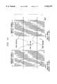
- FIG. 3shows greater detail of the analog to digital sampler and digitizer 140, as it samples a pilot tone pair consisting of a higher frequency and a lower frequency, a first traffic tone pair consisting of a higher frequency and a lower frequency, and a second traffic tone pair consisting of a higher frequency and a lower frequency.
- the remote station clock CLK 190is applied to a modulo N sampling window counter 302.
- the output of the Modulo N sampling window counter 302is the clock signal 190 divided by the integer N which is a reduced rate clock signal applied to the Modulo M observation window counter 310.
- the Modulo N sampling window counter 302provides a sampling window on/off signal to the sampling circuit 316.
- the Modulo M observation window counter 310applies an observation window on/off signal to the sampling circuit 316.
- the analog traffic and pilot tones 135are applied to the sampling circuit 316, in a manner which will be understood with reference to FIGS. 5A and 5B.
- the observation window Ahas a duration of M units of the clock signal 190.
- the observation window Aincludes a plurality of smaller sampling windows each of which has a duration of N units of the clock signal CLK 190N.
- Observation windowsare periodically applied to the sampling circuit 316 as is seen in FIG. 5A where observation window A and observation window A' are applied to the pilot tone pair.
- the sampling window adjust signal 137which is output from the sync block 150, controls the value of the quantity "N" for the Modulo N sampling window counter 302.
- the observation window adjust signal 145 from the sync block 150controls the value of the quantity "M" for the Modulo M observation window counter 310.
- the size or duration and the location in time of the observation windows A and A' and the sampling windows in FIG. 5Acan be controlled by the sync block 150.
- a first setting of the signals 137 and 145will provide the observation window A and observation window A' with a duration M and their sampling windows with a duration N, which are positioned in time as shown in FIG. 5A, for gathering samples of a pilot tone to characterize it's frequency. This will be shown in the frequency domain diagrams of FIGS. 4A, 4B, 4C, and 4D.
- the values for the adjustment signals 137 and 145can control the duration and location of the observation windows and sampling windows as shown in FIG. 5B.
- Observation windows B and B' and the sampling windows of FIG. 5Bhave different durations, M' and N', respectively, and different positions in time, which are suitable for the characterization of the time (or phase) characteristics of a pilot tone.
- Techniques for the detection of signals having an unknown time (or phase) shift and an unknown frequency shiftare described for example by R. N. McDonough, et al. "Detection of Signals in Noise", second edition, Academic Press, 1995.
- the output of the sampling circuit 316 in FIG. 3is the sampled values of input pilot one waveform, which is then digitized in the digitizer 318 to produce digital traffic and pilot ones 135'.
- the digitizationcan be pulse code modulation (PCM) or other forms of digitization of the sampled waveform for the traffic and pilot tones input to the sampling circuit 316.
- PCMpulse code modulation
- the FFT processor 210 in FIG. 2receives the digital traffic and pilot tones with symbol pattern 135' and performs a fast Fourier transform of the wave forms producing a frequency domain characterization as is shown in FIGS. 4A, 4B, 4C, and 4D.
- the frequency domain characterization of a pilot tonefor example, the lower frequency pilot tone of FIG. 5A, is applied to matched filter banks shown in FIG. 2.
- Two matched filter banksare shown in FIG. 2, one is characterized as a coarse bank, with a set of matched filters separated by a larger frequency span of 64 Hz., for example.
- the secondis characterized as a fine bank, with a set of matched filters separated by a smaller frequency span of 16 Hz., for example.
- the coarse matched filter bankconsists of a plurality of matched filters, of which only two are shown, F(0) 202C and F(n) 202C'. Each filter is followed by an envelope detector 204 or 204' and a threshold detector 206 or 206', respectively.
- the fast Fourier transformcan be viewed as a bank of matched filters.
- Each bank of matched filterscan be separated by a small frequency range .
- the coarse matched filter bank 202C-202C'can be separated by 64 Hz, as is shown in FIGS. 4A and 4B.
- the fine matched filter bankconsisting of matched filters 202F-202F' can be separated by smaller frequency range, such as 16 Hz as is shown in 4C and 4D.
- the fine matched filter bankhas the matched filter F(0) 202F followed by envelope detector 204" and threshold detector 206".
- the matched filter F(N) 202F'is followed by the envelope detector 204'" and the threshold detector 206'".
- Each matched filterimplements a time domain autocorrelation function in the frequency domain.
- the objective of a matched filter bankis to identify the particular frequency bin that has the maximum energy content for the fast Fourier transform of the input pilot tone signal.
- the expected frequency of the pilot toneis a center frequency FC.
- the oscillator frequency for the phase locked loop 160 in the remote stationmust be adjusted so as to move the apparent FFT bin with the largest energy to the center frequency FC. This is shown in the transition from FIG. 4A to FIG. 4B for the coarse filter bank.
- the estimated time delay and frequency offset processor 208 in FIG. 2identifies the FFT bin having the greatest energy. If the bin having the greatest energy is not the center frequency bin FC, then a correction signal is applied by processor 208. This causes the adjust oscillator frequency module 216 in FIG. 2 to apply a frequency adjustment signal to the oscillator in the phase locked loop 160 which is sufficient to shift the apparent bin having maximum energy to the center frequency FC, as is shown in FIG. 4B. This results in a new, second clock signal CLK 190.
- the estimated time delay and frequency offset processor 208applies an enabling signal to the symbol bit pattern recognition processor 212 in FIG. 2.
- a second sample of the pilot toneis taken, using the new, second CLK 190 clock signal.
- the pilot data 238 output from the spreader and decoder 180includes the symbol pattern 125" which is applied to an input of the pattern recognition processor 212. If the frequency and the time offset of the second clock signal CLK 190 is synchronized with that of the pilot tone, then the symbol pattern 125" will be the same as the symbol pattern 125 transmitted from the base station.
- a replica of the symbol pattern 125 transmitted from the base stationis stored as the reference pattern 234 in the symbol bit pattern recognition processor 212.
- the pattern recognition processor 212stores the reference pattern 234 which it will compare with the symbol 125". If there is a successful match, this indicates that both that both the frequency and the phase of the new, second clock signal CLK 190 are synchronized with that of the pilot tone sampled by the sampling circuit 316. This is a synchronization lock indication.
- the error signal 230is output by the recognition processor 212 to the estimated time delay and frequency offset processor 208.
- the processor 208then identifies the matched filter in the fine matched filter bank that has the maximum energy for the second sampled tone in the modified observation windows A and A' of FIG. 5A.
- the absolute position of the observation windows A and A' and the duration of the sampling windowsare a function of the current frequency of the CLK 190 clock signal, and thus they have changed as a result of the new second frequency of CLK 190.
- the modified observation windowhas its duration and location in the time domain governed by the newly adjusted clock signal CLK 190.
- the fine measurement of the frequency of the pilot toneis shown in FIG. 4C.
- a second adjustmentis made by the adjust oscillator frequency module 216 to the phase lock loop 160, to bring the oscillator frequency for the phase lock loop to a frequency that moves the apparent FFT bin with the largest frequency to the center frequency FC.
- the estimated time delay and frequency offset processor 208applies a second enable signal to the symbol bit pattern recognition processor 212.
- a third sampleis taken of the pilot tone, using the new, third clock signal CLK 190.
- the third sample of the pilot toneis used to determine if the pilot data 238 with the symbol pattern 125" will successfully match the reference pattern 234. If there is a successful match, then both the phase and the frequency of the oscillator in the phase locked loop 160 are in synchronization with the incoming pilot tone. This is a synchronization lock indication.
- the error signal 230is applied to the processor 208.
- the processor 208then outputs adjustment signals on the sampling window adjust line 137 and the observation window adjust line 145 to alter the configuration of the observation windows A and A' and the sampling windows to become windows B and B' shown in FIG. 5B.
- Windows B and B'are suitable for measuring the time offset or phase error between the clock signal 190 and the received pilot tone.
- the lower frequency pilot toneis sampled using the new, third clock signal CLK 190 as is shown in FIG. 5B, digitized, and applied to the fast Fourier processor 210.
- the resulting transformed frequency domain characterization of the pilot toneis then applied to the estimated them delay and frequency offset processor 208 which determines the phase or timing error between a clock signal CLK 190 and the pilot tone.
- the FFT transformed datacan be input to processor 208 on line 245, where an inverse FFT is carried out followed by a zero crossing detection in the time domain.
- Other techniques suggested by the McDonough, et al reference cited above,can be used by the processor 208 to estimate the time delay of the CLK 190 signal with respect to the pilot tone.
- an adjust time offsetis applied by the module 214 to the clock circuit 170 to displace in time the clock signal CLK 190 so as to bring it in to time synchronization with the pilot tone.
- Clock pulsescan be added or removed from the CLK 190 signal, for example. This results in a fourth clock signal CLK 190. A fourth sample is then taken of the pilot tone.
- the synchronization of the time or phase and frequency of the clock signal CLK 190 with the pilot toneis confirmed by performing a third matching operation in the processor 212 between the symbol pattern 125" and the reference pattern 234. If there is a good match, then the processor 212 enables the remote station to process traffic data 236, since the spread signal received from the base station Z are now synchronized with the clock signal CLK 190 in the remote station X. This is a synchronization lock indication. However, if there is not a good match, the processor 208 repeats the time offset adjustment with module 214 and continues the process of matching with the reference pattern in processor 212 until a steady state synchronization is achieved.
- FIG. 6is a flow diagram 800 of the sequence of operational steps carried out by the base station and the remote station in accordance with the invention.
- the flow diagram 800 of FIG. 6carries out the steps as follows:
- Step 810Base Station: Generate and transmit symbol pattern in pilot tones.
- Step 820Remote Station: Receive analog traffic and Pilot tones with symbol pattern 125.
- Step 830Remote Station: Set observation and sampling windows as shown in FIG. 5A. Digitize and perform FFT on pilot tones for frequency error.
- Step 840Remote Station: Apply transformed symbol pattern 125' to coarse matched-filter bank (FIGS. 4A and 4B) and adjust oscillator frequency to move FFT bin with the largest energy to center frequency FC.
- Step 850Remote Station: Apply frequency error to PLL and then decode symbol pattern 125" and apply to recognition processor to compare with reference pattern 234.
- Step 860Remote Station: If compare fails, then apply symbol pattern 125' to fine filter bank (FIGS. 4C and 4D) and adjust oscillator frequency to move FFT bin with largest energy to center frequency FC.
- Step 870Remote Station: Apply frequency error to PLL and then decode symbol pattern 125" and apply to recognition processor to compare with reference pattern 234.
- Step 880Remote Station: If compare 870 fails, then set observation and sampling windows as shown in FIG. 5B and perform FFT on pilot tones for time error.
- Step 890Remote Station: Apply time error to clock CLK and then decode symbol pattern 125" and apply to recognition processor to compare with reference pattern 234.
- Step 900Remote Station: If compare 890 is good, then keep settings for observation and sampling windows and process received traffic. Loop back to step 820 to continue monitoring and adjusting the synchronization.
- Still another alternate embodimentapplies the above described invention in the PWAN Frequency Division Duplex Communications System described in the Alamouti, Michaelson et al. patent application cited above.
Landscapes
- Engineering & Computer Science (AREA)
- Signal Processing (AREA)
- Computer Networks & Wireless Communication (AREA)
- Mobile Radio Communication Systems (AREA)
- Synchronisation In Digital Transmission Systems (AREA)
Abstract
Description
Claims (12)
Priority Applications (5)
| Application Number | Priority Date | Filing Date | Title |
|---|---|---|---|
| US08/796,492US5943375A (en) | 1997-02-06 | 1997-02-06 | Method to indicate synchronization lock of a remote station with a base station |
| PCT/US1998/001453WO1998035455A1 (en) | 1997-02-06 | 1998-02-03 | Method of synchronizing a remote station with a base station in a discrete multitone spread spectrum communications system |
| PCT/US1998/002077WO1998035458A1 (en) | 1997-02-06 | 1998-02-06 | Method of synchronizing a remote station with a base station in a discrete multitone spread spectrum communications system |
| US09/095,747US6084932A (en) | 1997-02-06 | 1998-06-11 | Method to indicate synchronization lock of a remote station with a base station for a discrete multitone spread spectrum communications system |
| US14/246,272US9088388B2 (en) | 1997-02-06 | 2014-04-07 | Method for frequency division duplex communications |
Applications Claiming Priority (1)
| Application Number | Priority Date | Filing Date | Title |
|---|---|---|---|
| US08/796,492US5943375A (en) | 1997-02-06 | 1997-02-06 | Method to indicate synchronization lock of a remote station with a base station |
Related Child Applications (1)
| Application Number | Title | Priority Date | Filing Date |
|---|---|---|---|
| US08/804,617Continuation-In-PartUS5914981A (en) | 1997-02-06 | 1997-02-24 | Method to indicate synchronization lock of a remote station with a base station for a discrete multitone spread spectrum communications system |
Publications (1)
| Publication Number | Publication Date |
|---|---|
| US5943375Atrue US5943375A (en) | 1999-08-24 |
Family
ID=25168313
Family Applications (1)
| Application Number | Title | Priority Date | Filing Date |
|---|---|---|---|
| US08/796,492Expired - LifetimeUS5943375A (en) | 1997-02-06 | 1997-02-06 | Method to indicate synchronization lock of a remote station with a base station |
Country Status (2)
| Country | Link |
|---|---|
| US (1) | US5943375A (en) |
| WO (1) | WO1998035455A1 (en) |
Cited By (50)
| Publication number | Priority date | Publication date | Assignee | Title |
|---|---|---|---|---|
| US6097776A (en)* | 1998-02-12 | 2000-08-01 | Cirrus Logic, Inc. | Maximum likelihood estimation of symbol offset |
| US6134260A (en)* | 1997-12-16 | 2000-10-17 | Ericsson Inc. | Method and apparatus for frequency acquisition and tracking for DS-SS CDMA receivers |
| US6320911B1 (en)* | 1997-07-15 | 2001-11-20 | Alcatel | System for providing information relating to the source frequency in a digital receive-transmit system |
| US20020122465A1 (en)* | 1997-02-24 | 2002-09-05 | Agee Brian G. | Highly bandwidth-efficient communications |
| US6459883B2 (en)* | 2000-07-31 | 2002-10-01 | Morphics Technology, Inc. | Generic finger architecture for spread spectrum applications |
| US20030053488A1 (en)* | 1997-02-06 | 2003-03-20 | At&T Wireless Services, Inc. | Delay compensation |
| US6560209B1 (en) | 1997-02-06 | 2003-05-06 | At&T Wireless Services, Inc. | Method for frequency division duplex communications |
| US6700866B1 (en)* | 1999-06-23 | 2004-03-02 | At&T Wireless Services, Inc. | Methods and apparatus for use in obtaining frequency synchronization in an OFDM communication system |
| US6700902B1 (en) | 1998-10-19 | 2004-03-02 | Elster Electricity, Llc | Method and system for improving wireless data packet delivery |
| US6701133B1 (en)* | 1997-11-03 | 2004-03-02 | Fairfield Industries, Inc. | Apparatus for and method of synchronising oscillators within a data communication system |
| US6782039B2 (en) | 1997-02-24 | 2004-08-24 | At&T Wireless Services, Inc. | Vertical adaptive antenna array for a discrete multitone spread spectrum communications system |
| US6867707B1 (en) | 2002-04-24 | 2005-03-15 | Elster Electricity, Llc | Automated on-site meter registration confirmation using a portable, wireless computing device |
| US20050195863A1 (en)* | 2004-03-02 | 2005-09-08 | International Business Machines Corporation | Circuit and method for providing automatic adaptation to frequency offsets in high speed serial links |
| US6975668B2 (en) | 1997-02-24 | 2005-12-13 | Cingular Wireless Ii, Llc | Adaptive weight update method and system for a discrete multitone spread spectrum communications system |
| US20060058027A1 (en)* | 2004-09-14 | 2006-03-16 | Motorola, Inc. | Method and apparatus for carrier frequency estimation and correction for GPS |
| US7046682B2 (en) | 1997-02-12 | 2006-05-16 | Elster Electricity, Llc. | Network-enabled, extensible metering system |
| US7119713B2 (en) | 2002-06-27 | 2006-10-10 | Elster Electricity, Llc | Dynamic self-configuring metering network |
| US7126494B2 (en) | 1997-02-12 | 2006-10-24 | Elster Electricity, Llc | Remote access to electronic meters using a TCP/IP protocol suite |
| US7142106B2 (en) | 2004-06-15 | 2006-11-28 | Elster Electricity, Llc | System and method of visualizing network layout and performance characteristics in a wireless network |
| US7170425B2 (en) | 2004-09-24 | 2007-01-30 | Elster Electricity, Llc | System and method for creating multiple operating territories within a meter reading system |
| US7176807B2 (en) | 2004-09-24 | 2007-02-13 | Elster Electricity, Llc | System for automatically enforcing a demand reset in a fixed network of electricity meters |
| US7187906B2 (en) | 2004-04-26 | 2007-03-06 | Elster Electricity, Llc | Method and system for configurable qualification and registration in a fixed network automated meter reading system |
| US7209494B1 (en)* | 2000-10-24 | 2007-04-24 | L-3 Communications Corporation | Digital reverse transmission frequency training method for time division duplex (TDD) communication system |
| US7227350B2 (en) | 2004-03-18 | 2007-06-05 | Elster Electricity, Llc | Bias technique for electric utility meter |
| US7239250B2 (en) | 2004-04-26 | 2007-07-03 | Elster Electricity, Llc | System and method for improved transmission of meter data |
| US7262709B2 (en) | 2004-04-26 | 2007-08-28 | Elster Electricity, Llc | System and method for efficient configuration in a fixed network automated meter reading system |
| US7308369B2 (en) | 2005-09-28 | 2007-12-11 | Elster Electricity Llc | Ensuring automatic season change demand resets in a mesh type network of telemetry devices |
| US7308370B2 (en) | 2005-03-22 | 2007-12-11 | Elster Electricity Llc | Using a fixed network wireless data collection system to improve utility responsiveness to power outages |
| US7312721B2 (en) | 2002-06-28 | 2007-12-25 | Elster Electricity, Llc | Data collector for an automated meter reading system |
| US20070297540A1 (en)* | 2006-06-22 | 2007-12-27 | Navini Networks, Inc. | Method and system for detecting preambles in a multi-cell system |
| US7315162B2 (en) | 2004-03-18 | 2008-01-01 | Elster Electricity, Llc | Reducing power consumption of electrical meters |
| US7327998B2 (en) | 2004-12-22 | 2008-02-05 | Elster Electricity, Llc | System and method of providing a geographic view of nodes in a wireless network |
| US7427927B2 (en) | 2006-02-16 | 2008-09-23 | Elster Electricity, Llc | In-home display communicates with a fixed network meter reading system |
| US20090013081A1 (en)* | 2007-07-06 | 2009-01-08 | Qualcomm Incorporated | Methods and apparatus related to peer discovery and/or paging in peer to peer wireless communications |
| US20090010231A1 (en)* | 2007-07-06 | 2009-01-08 | Qualcomm Incorporated | Communications methods and apparatus related to synchronization with respect to a peer to peer timing structure |
| US20090010244A1 (en)* | 2007-07-06 | 2009-01-08 | Qualcomm Incorporated | Methods and apparatus supporting multiple timing synchronizations corresponding to different communications peers |
| US20090010179A1 (en)* | 2007-07-05 | 2009-01-08 | Qualcomm Incorporated | Methods and apparatus supporting traffic signaling in peer to peer communications |
| US20090010232A1 (en)* | 2007-07-06 | 2009-01-08 | Qualcomm Incorporated | Methods and apparatus related to peer to peer communications timing structure |
| US7495578B2 (en) | 2005-09-02 | 2009-02-24 | Elster Electricity, Llc | Multipurpose interface for an automated meter reading device |
| US7545285B2 (en) | 2006-02-16 | 2009-06-09 | Elster Electricity, Llc | Load control unit in communication with a fixed network meter reading system |
| US7702594B2 (en) | 2004-09-24 | 2010-04-20 | Elster Electricity, Llc | System and method for automated configuration of meters |
| US7742430B2 (en) | 2004-09-24 | 2010-06-22 | Elster Electricity, Llc | System for automated management of spontaneous node migration in a distributed fixed wireless network |
| US8073384B2 (en) | 2006-12-14 | 2011-12-06 | Elster Electricity, Llc | Optimization of redundancy and throughput in an automated meter data collection system using a wireless network |
| US8203463B2 (en) | 2009-02-13 | 2012-06-19 | Elster Electricity Llc | Wakeup and interrogation of meter-reading devices using licensed narrowband and unlicensed wideband radio communication |
| US8320302B2 (en) | 2007-04-20 | 2012-11-27 | Elster Electricity, Llc | Over the air microcontroller flash memory updates |
| US8525692B2 (en) | 2008-06-13 | 2013-09-03 | Elster Solutions, Llc | Techniques for limiting demand from an electricity meter with an installed relay |
| US8738020B2 (en) | 2000-12-15 | 2014-05-27 | Adaptix, Inc. | Multi-carrier communications with adaptive cluster configuration and switching |
| US8760992B2 (en) | 2004-12-07 | 2014-06-24 | Adaptix, Inc. | Method and system for switching antenna and channel assignments in broadband wireless networks |
| US9612132B2 (en) | 2007-12-26 | 2017-04-04 | Elster Solutions, Llc | Optimized data collection in a wireless fixed network metering system |
| US11616587B1 (en)* | 2020-11-30 | 2023-03-28 | Meta Platforms, Inc. | Remote clock synchronization using network communication and satellite signals |
Families Citing this family (3)
| Publication number | Priority date | Publication date | Assignee | Title |
|---|---|---|---|---|
| DE19722114C2 (en)* | 1997-05-27 | 2003-04-30 | Bosch Gmbh Robert | Clock signal providing device and method |
| DE102004035532B4 (en)* | 2004-07-22 | 2010-06-10 | Fraunhofer-Gesellschaft zur Förderung der angewandten Forschung e.V. | Apparatus and method for generating a reference clock transmission signal and deriving a reference clock therefrom |
| US8787432B1 (en)* | 2013-03-14 | 2014-07-22 | Harris Corporation | HF communication system with decoding operations and related methods |
Citations (12)
| Publication number | Priority date | Publication date | Assignee | Title |
|---|---|---|---|---|
| US4599732A (en)* | 1984-04-17 | 1986-07-08 | Harris Corporation | Technique for acquiring timing and frequency synchronization for modem utilizing known (non-data) symbols as part of their normal transmitted data format |
| US5282228A (en)* | 1991-12-09 | 1994-01-25 | Novatel Communications Ltd. | Timing and automatic frequency control of digital receiver using the cyclic properties of a non-linear operation |
| EP0630120A1 (en)* | 1993-06-16 | 1994-12-21 | Matra Communication | Synchronisation method for radio telephone communications with code division multiplex access |
| US5428647A (en)* | 1992-12-07 | 1995-06-27 | Motorola, Inc. | Method and apparatus for synchronizing a received signal in a digital radio communication system |
| EP0675606A1 (en)* | 1993-10-13 | 1995-10-04 | Ntt Mobile Communications Network Inc. | Receiver for spread spectrum communication |
| US5490174A (en)* | 1993-07-12 | 1996-02-06 | Samsung Electronics Co., Ltd. | Digital data receiver |
| EP0704985A2 (en)* | 1994-09-28 | 1996-04-03 | Roke Manor Research Limited | Clock phase adjustment circuit in a RAKE receiver for spread spectrum signals |
| US5537419A (en)* | 1991-06-27 | 1996-07-16 | Hughes Electronics | Receiver sample timing adjustment using channel impulse response |
| EP0749213A2 (en)* | 1995-06-15 | 1996-12-18 | Nec Corporation | Spread spectrum signal receiving apparatus |
| WO1997002675A2 (en)* | 1995-06-30 | 1997-01-23 | Interdigital Technology Corporation | Cdma modem |
| US5627855A (en)* | 1995-05-25 | 1997-05-06 | Golden Bridge Technology, Inc. | Programmable two-part matched filter for spread spectrum |
| US5659573A (en)* | 1994-10-04 | 1997-08-19 | Motorola, Inc. | Method and apparatus for coherent reception in a spread-spectrum receiver |
- 1997
- 1997-02-06USUS08/796,492patent/US5943375A/ennot_activeExpired - Lifetime
- 1998
- 1998-02-03WOPCT/US1998/001453patent/WO1998035455A1/enactiveApplication Filing
Patent Citations (12)
| Publication number | Priority date | Publication date | Assignee | Title |
|---|---|---|---|---|
| US4599732A (en)* | 1984-04-17 | 1986-07-08 | Harris Corporation | Technique for acquiring timing and frequency synchronization for modem utilizing known (non-data) symbols as part of their normal transmitted data format |
| US5537419A (en)* | 1991-06-27 | 1996-07-16 | Hughes Electronics | Receiver sample timing adjustment using channel impulse response |
| US5282228A (en)* | 1991-12-09 | 1994-01-25 | Novatel Communications Ltd. | Timing and automatic frequency control of digital receiver using the cyclic properties of a non-linear operation |
| US5428647A (en)* | 1992-12-07 | 1995-06-27 | Motorola, Inc. | Method and apparatus for synchronizing a received signal in a digital radio communication system |
| EP0630120A1 (en)* | 1993-06-16 | 1994-12-21 | Matra Communication | Synchronisation method for radio telephone communications with code division multiplex access |
| US5490174A (en)* | 1993-07-12 | 1996-02-06 | Samsung Electronics Co., Ltd. | Digital data receiver |
| EP0675606A1 (en)* | 1993-10-13 | 1995-10-04 | Ntt Mobile Communications Network Inc. | Receiver for spread spectrum communication |
| EP0704985A2 (en)* | 1994-09-28 | 1996-04-03 | Roke Manor Research Limited | Clock phase adjustment circuit in a RAKE receiver for spread spectrum signals |
| US5659573A (en)* | 1994-10-04 | 1997-08-19 | Motorola, Inc. | Method and apparatus for coherent reception in a spread-spectrum receiver |
| US5627855A (en)* | 1995-05-25 | 1997-05-06 | Golden Bridge Technology, Inc. | Programmable two-part matched filter for spread spectrum |
| EP0749213A2 (en)* | 1995-06-15 | 1996-12-18 | Nec Corporation | Spread spectrum signal receiving apparatus |
| WO1997002675A2 (en)* | 1995-06-30 | 1997-01-23 | Interdigital Technology Corporation | Cdma modem |
Cited By (96)
| Publication number | Priority date | Publication date | Assignee | Title |
|---|---|---|---|---|
| US20080298339A1 (en)* | 1997-02-06 | 2008-12-04 | Siavash Alamouti | Method for frequency division duplex communications |
| US7460561B2 (en) | 1997-02-06 | 2008-12-02 | Clearwire Corporation | Delay compensation |
| US8693432B2 (en) | 1997-02-06 | 2014-04-08 | At&T Mobility Ii Llc | Method for frequency division duplex communications |
| US8305990B2 (en) | 1997-02-06 | 2012-11-06 | At&T Mobility Ii Llc | Method for frequency division duplex communications |
| US7983217B2 (en) | 1997-02-06 | 2011-07-19 | At&T Mobility Ii Llc | Method for frequency division duplex communications |
| US20030053488A1 (en)* | 1997-02-06 | 2003-03-20 | At&T Wireless Services, Inc. | Delay compensation |
| US9088388B2 (en) | 1997-02-06 | 2015-07-21 | At&T Mobility Ii Llc | Method for frequency division duplex communications |
| US6560209B1 (en) | 1997-02-06 | 2003-05-06 | At&T Wireless Services, Inc. | Method for frequency division duplex communications |
| US20050180349A1 (en)* | 1997-02-06 | 2005-08-18 | Siavash Alamouti | Method for frequency division duplex communications |
| US6853629B2 (en) | 1997-02-06 | 2005-02-08 | Cingular Wireless Ii, Llc | Method for frequency division duplex communications |
| US7450542B2 (en)* | 1997-02-06 | 2008-11-11 | At&T Mobility Ii Llc | Method for frequency division duplex communications |
| US6785300B2 (en)* | 1997-02-06 | 2004-08-31 | At&T Wireless Services, Inc. | Delay compensation |
| US20040264549A1 (en)* | 1997-02-06 | 2004-12-30 | Elliott Hoole | Delay compensation |
| US7126494B2 (en) | 1997-02-12 | 2006-10-24 | Elster Electricity, Llc | Remote access to electronic meters using a TCP/IP protocol suite |
| US7505453B2 (en) | 1997-02-12 | 2009-03-17 | Elster Electricity, Llc | Network-enabled, extensible metering system |
| US7046682B2 (en) | 1997-02-12 | 2006-05-16 | Elster Electricity, Llc. | Network-enabled, extensible metering system |
| US7106781B2 (en) | 1997-02-24 | 2006-09-12 | Cingular Wireless Ii, Llc | Highly bandwidth-efficient communications |
| US6975668B2 (en) | 1997-02-24 | 2005-12-13 | Cingular Wireless Ii, Llc | Adaptive weight update method and system for a discrete multitone spread spectrum communications system |
| US20020122465A1 (en)* | 1997-02-24 | 2002-09-05 | Agee Brian G. | Highly bandwidth-efficient communications |
| US7061969B2 (en) | 1997-02-24 | 2006-06-13 | Cingular Wireless Ii, Llc | Vertical adaptive antenna array for a discrete multitone spread spectrum communication system |
| US20060193373A1 (en)* | 1997-02-24 | 2006-08-31 | Agee Brian G | Highly bandwidth-efficient communications |
| US6782039B2 (en) | 1997-02-24 | 2004-08-24 | At&T Wireless Services, Inc. | Vertical adaptive antenna array for a discrete multitone spread spectrum communications system |
| US20050002440A1 (en)* | 1997-02-24 | 2005-01-06 | Siavash Alamouti | Vertical adaptive antenna array for a discrete multitone spread spectrum communications system |
| US7149238B2 (en) | 1997-02-24 | 2006-12-12 | Cingular Wireless Ii, Llc | Highly bandwidth-efficient communications |
| US6320911B1 (en)* | 1997-07-15 | 2001-11-20 | Alcatel | System for providing information relating to the source frequency in a digital receive-transmit system |
| US6701133B1 (en)* | 1997-11-03 | 2004-03-02 | Fairfield Industries, Inc. | Apparatus for and method of synchronising oscillators within a data communication system |
| US6134260A (en)* | 1997-12-16 | 2000-10-17 | Ericsson Inc. | Method and apparatus for frequency acquisition and tracking for DS-SS CDMA receivers |
| US6097776A (en)* | 1998-02-12 | 2000-08-01 | Cirrus Logic, Inc. | Maximum likelihood estimation of symbol offset |
| US6700902B1 (en) | 1998-10-19 | 2004-03-02 | Elster Electricity, Llc | Method and system for improving wireless data packet delivery |
| US6700866B1 (en)* | 1999-06-23 | 2004-03-02 | At&T Wireless Services, Inc. | Methods and apparatus for use in obtaining frequency synchronization in an OFDM communication system |
| US6459883B2 (en)* | 2000-07-31 | 2002-10-01 | Morphics Technology, Inc. | Generic finger architecture for spread spectrum applications |
| US7209494B1 (en)* | 2000-10-24 | 2007-04-24 | L-3 Communications Corporation | Digital reverse transmission frequency training method for time division duplex (TDD) communication system |
| US8964719B2 (en) | 2000-12-15 | 2015-02-24 | Adaptix, Inc. | OFDMA with adaptive subcarrier-cluster configuration and selective loading |
| US8743717B2 (en) | 2000-12-15 | 2014-06-03 | Adaptix, Inc. | Multi-carrier communications with adaptive cluster configuration and switching |
| US9191138B2 (en) | 2000-12-15 | 2015-11-17 | Adaptix, Inc. | OFDMA with adaptive subcarrier-cluster configuration and selective loading |
| US9344211B2 (en) | 2000-12-15 | 2016-05-17 | Adaptix, Inc. | OFDMA with adaptive subcarrier-cluster configuration and selective loading |
| US8738020B2 (en) | 2000-12-15 | 2014-05-27 | Adaptix, Inc. | Multi-carrier communications with adaptive cluster configuration and switching |
| US9203553B1 (en) | 2000-12-15 | 2015-12-01 | Adaptix, Inc. | OFDMA with adaptive subcarrier-cluster configuration and selective loading |
| US8958386B2 (en) | 2000-12-15 | 2015-02-17 | Adaptix, Inc. | Multi-carrier communications with adaptive cluster configuration and switching |
| US8743729B2 (en) | 2000-12-15 | 2014-06-03 | Adaptix, Inc. | Multi-carrier communications with adaptive cluster configuration and switching |
| US8934375B2 (en) | 2000-12-15 | 2015-01-13 | Adaptix, Inc. | OFDMA with adaptive subcarrier-cluster configuration and selective loading |
| US8934445B2 (en) | 2000-12-15 | 2015-01-13 | Adaptix, Inc. | Multi-carrier communications with adaptive cluster configuration and switching |
| US8750238B2 (en) | 2000-12-15 | 2014-06-10 | Adaptix, Inc. | Multi-carrier communications with adaptive cluster configuration and switching |
| US8891414B2 (en) | 2000-12-15 | 2014-11-18 | Adaptix, Inc. | Multi-carrier communications with adaptive cluster configuration and switching |
| US9219572B2 (en) | 2000-12-15 | 2015-12-22 | Adaptix, Inc. | OFDMA with adaptive subcarrier-cluster configuration and selective loading |
| US8767702B2 (en) | 2000-12-15 | 2014-07-01 | Adaptix, Inc. | Multi-carrier communications with adaptive cluster configuration and switching |
| US9210708B1 (en) | 2000-12-15 | 2015-12-08 | Adaptix, Inc. | OFDMA with adaptive subcarrier-cluster configuration and selective loading |
| US6867707B1 (en) | 2002-04-24 | 2005-03-15 | Elster Electricity, Llc | Automated on-site meter registration confirmation using a portable, wireless computing device |
| US7145474B2 (en) | 2002-06-27 | 2006-12-05 | Elster Electricity, Llc | Dynamic self-configuring metering network |
| US7301476B2 (en) | 2002-06-27 | 2007-11-27 | Elster Electricity, Llc | Dynamic self-configuring metering network |
| US7119713B2 (en) | 2002-06-27 | 2006-10-10 | Elster Electricity, Llc | Dynamic self-configuring metering network |
| US7312721B2 (en) | 2002-06-28 | 2007-12-25 | Elster Electricity, Llc | Data collector for an automated meter reading system |
| US7477713B2 (en) | 2004-03-02 | 2009-01-13 | International Business Machines Corporation | method for providing automatic adaptation to frequency offsets in high speed serial links |
| US20050195863A1 (en)* | 2004-03-02 | 2005-09-08 | International Business Machines Corporation | Circuit and method for providing automatic adaptation to frequency offsets in high speed serial links |
| US20090116593A1 (en)* | 2004-03-02 | 2009-05-07 | International Business Machines Corporation | Circuit for providing automatic adaptation to frequency offsets in high speed serial links |
| US7417420B2 (en) | 2004-03-18 | 2008-08-26 | Elster Electricity, Llc | Switch to bypass optical diode for reducing power consumption of electrical meters |
| US7315162B2 (en) | 2004-03-18 | 2008-01-01 | Elster Electricity, Llc | Reducing power consumption of electrical meters |
| US7227350B2 (en) | 2004-03-18 | 2007-06-05 | Elster Electricity, Llc | Bias technique for electric utility meter |
| US7262709B2 (en) | 2004-04-26 | 2007-08-28 | Elster Electricity, Llc | System and method for efficient configuration in a fixed network automated meter reading system |
| US7187906B2 (en) | 2004-04-26 | 2007-03-06 | Elster Electricity, Llc | Method and system for configurable qualification and registration in a fixed network automated meter reading system |
| US7239250B2 (en) | 2004-04-26 | 2007-07-03 | Elster Electricity, Llc | System and method for improved transmission of meter data |
| US7142106B2 (en) | 2004-06-15 | 2006-11-28 | Elster Electricity, Llc | System and method of visualizing network layout and performance characteristics in a wireless network |
| US20060058027A1 (en)* | 2004-09-14 | 2006-03-16 | Motorola, Inc. | Method and apparatus for carrier frequency estimation and correction for GPS |
| US7702594B2 (en) | 2004-09-24 | 2010-04-20 | Elster Electricity, Llc | System and method for automated configuration of meters |
| US7742430B2 (en) | 2004-09-24 | 2010-06-22 | Elster Electricity, Llc | System for automated management of spontaneous node migration in a distributed fixed wireless network |
| US7176807B2 (en) | 2004-09-24 | 2007-02-13 | Elster Electricity, Llc | System for automatically enforcing a demand reset in a fixed network of electricity meters |
| US7170425B2 (en) | 2004-09-24 | 2007-01-30 | Elster Electricity, Llc | System and method for creating multiple operating territories within a meter reading system |
| US8760992B2 (en) | 2004-12-07 | 2014-06-24 | Adaptix, Inc. | Method and system for switching antenna and channel assignments in broadband wireless networks |
| US8797970B2 (en) | 2004-12-07 | 2014-08-05 | Adaptix, Inc. | Method and system for switching antenna and channel assignments in broadband wireless networks |
| US7327998B2 (en) | 2004-12-22 | 2008-02-05 | Elster Electricity, Llc | System and method of providing a geographic view of nodes in a wireless network |
| US7308370B2 (en) | 2005-03-22 | 2007-12-11 | Elster Electricity Llc | Using a fixed network wireless data collection system to improve utility responsiveness to power outages |
| US7495578B2 (en) | 2005-09-02 | 2009-02-24 | Elster Electricity, Llc | Multipurpose interface for an automated meter reading device |
| US7308369B2 (en) | 2005-09-28 | 2007-12-11 | Elster Electricity Llc | Ensuring automatic season change demand resets in a mesh type network of telemetry devices |
| US7427927B2 (en) | 2006-02-16 | 2008-09-23 | Elster Electricity, Llc | In-home display communicates with a fixed network meter reading system |
| US7545285B2 (en) | 2006-02-16 | 2009-06-09 | Elster Electricity, Llc | Load control unit in communication with a fixed network meter reading system |
| CN101467358B (en)* | 2006-06-22 | 2013-03-06 | 思科技术公司 | Method and system for detecting preambles in a multi-cell system |
| US20070297540A1 (en)* | 2006-06-22 | 2007-12-27 | Navini Networks, Inc. | Method and system for detecting preambles in a multi-cell system |
| WO2007149133A2 (en) | 2006-06-22 | 2007-12-27 | Navini Networks, Inc. | Method and system for detecting preambles in a multi-cell system |
| EP2033453A4 (en)* | 2006-06-22 | 2011-09-14 | Cisco Tech Inc | Method and system for detecting preambles in a multi-cell system |
| US7991083B2 (en)* | 2006-06-22 | 2011-08-02 | Cisco Technology, Inc. | Method and system for detecting preambles in a multi-cell system |
| US8073384B2 (en) | 2006-12-14 | 2011-12-06 | Elster Electricity, Llc | Optimization of redundancy and throughput in an automated meter data collection system using a wireless network |
| US8320302B2 (en) | 2007-04-20 | 2012-11-27 | Elster Electricity, Llc | Over the air microcontroller flash memory updates |
| US20090010179A1 (en)* | 2007-07-05 | 2009-01-08 | Qualcomm Incorporated | Methods and apparatus supporting traffic signaling in peer to peer communications |
| US7898983B2 (en) | 2007-07-05 | 2011-03-01 | Qualcomm Incorporated | Methods and apparatus supporting traffic signaling in peer to peer communications |
| US8599823B2 (en)* | 2007-07-06 | 2013-12-03 | Qualcomm Incorporated | Communications methods and apparatus related to synchronization with respect to a peer to peer timing structure |
| US20090010244A1 (en)* | 2007-07-06 | 2009-01-08 | Qualcomm Incorporated | Methods and apparatus supporting multiple timing synchronizations corresponding to different communications peers |
| US20090010232A1 (en)* | 2007-07-06 | 2009-01-08 | Qualcomm Incorporated | Methods and apparatus related to peer to peer communications timing structure |
| US8601156B2 (en) | 2007-07-06 | 2013-12-03 | Qualcomm Incorporated | Methods and apparatus related to peer discovery and/or paging in peer to peer wireless communications |
| US20090013081A1 (en)* | 2007-07-06 | 2009-01-08 | Qualcomm Incorporated | Methods and apparatus related to peer discovery and/or paging in peer to peer wireless communications |
| US8385316B2 (en) | 2007-07-06 | 2013-02-26 | Qualcomm Incorporated | Methods and apparatus related to peer to peer communications timing structure |
| US8385317B2 (en) | 2007-07-06 | 2013-02-26 | Qualcomm Incorporated | Methods and apparatus supporting multiple timing synchronizations corresponding to different communications peers |
| US20090010231A1 (en)* | 2007-07-06 | 2009-01-08 | Qualcomm Incorporated | Communications methods and apparatus related to synchronization with respect to a peer to peer timing structure |
| US9612132B2 (en) | 2007-12-26 | 2017-04-04 | Elster Solutions, Llc | Optimized data collection in a wireless fixed network metering system |
| US8525692B2 (en) | 2008-06-13 | 2013-09-03 | Elster Solutions, Llc | Techniques for limiting demand from an electricity meter with an installed relay |
| US8203463B2 (en) | 2009-02-13 | 2012-06-19 | Elster Electricity Llc | Wakeup and interrogation of meter-reading devices using licensed narrowband and unlicensed wideband radio communication |
| US11616587B1 (en)* | 2020-11-30 | 2023-03-28 | Meta Platforms, Inc. | Remote clock synchronization using network communication and satellite signals |
Also Published As
| Publication number | Publication date |
|---|---|
| WO1998035455A1 (en) | 1998-08-13 |
Similar Documents
| Publication | Publication Date | Title |
|---|---|---|
| US5943375A (en) | Method to indicate synchronization lock of a remote station with a base station | |
| US6084932A (en) | Method to indicate synchronization lock of a remote station with a base station for a discrete multitone spread spectrum communications system | |
| US5914981A (en) | Method to indicate synchronization lock of a remote station with a base station for a discrete multitone spread spectrum communications system | |
| US5590160A (en) | Symbol and frame synchronization in both a TDMA system and a CDMA | |
| CA1296772C (en) | Digital radio transmission system for a cellular network, using the spread spectrum method | |
| US5805585A (en) | Method for providing high speed packet data services for a wireless system | |
| AU700456B2 (en) | Code acquisition in a cdma communication system using multiple walsh channels | |
| US6134233A (en) | Apparatus and method of frame aligning information in a wireless telecommunications system | |
| US5742583A (en) | Antenna diversity techniques | |
| FI87712B (en) | RADIOSYSTEM MED TIDDELNING SOM UTNYTTJAR BINAER FASNYCKLINGSSYNKRONISERING FOER KVADRATURFASNYCKLINGSSIGNALER SOM UTSAETTS FOER SLUMPARTADE FASVARIATIONER OCH FLERVAEGSFADNING | |
| US5111478A (en) | Method and apparatus for providing signal synchronization in a spread spectrum communication system | |
| US5832022A (en) | Method and apparatus for controlling the modulation index of continuous phase modulated (CPM) signals | |
| EP0605188A2 (en) | Symbol and frame synchronization for a TDMA system | |
| KR20040111501A (en) | Transceiver device | |
| KR19990022313A (en) | Apparatus and method for controlling transmission power and transmission speed of wireless telecommunication system | |
| NO170446B (en) | PROCEDURE AND DEVICE FOR SYNCHRONIZING RECEIVER DEVICES BY A DIGITAL MULTIPLE PLEASE TRANSMISSION SYSTEM | |
| US5896425A (en) | Non-uniformly spaced tones for synchronization waveform | |
| WO1998037674A9 (en) | Non-uniformly spaced tones for synchronization waveform | |
| JPH10510406A (en) | OCDMA code tracking system with phantom carrier signal | |
| JP3727510B2 (en) | Frame and method and apparatus for use in a time division multiple access (TDMA) wireless system | |
| US5914961A (en) | Fixed wireless loop system having dual direct synthesizer | |
| EP0931390B1 (en) | Improved synchronization of a receiver with a transmitter using nonlinear transformation metrics | |
| EP0903869A2 (en) | Clock regenerating circuit in direct sequence spread spectrum communication system | |
| US6324208B1 (en) | Apparatus and method of controlling transmitting power in a subscriber of a wireless telecommunications system | |
| JP3518756B2 (en) | Orthogonal frequency division multiplex signal transmission apparatus and orthogonal frequency division multiplex signal transmission method |
Legal Events
| Date | Code | Title | Description |
|---|---|---|---|
| AS | Assignment | Owner name:AT&T WIRELESS SERVICES, INC., WASHINGTON Free format text:ASSIGNMENT OF ASSIGNORS INTEREST;ASSIGNOR:VEINTIMILLA, GREGORY J.;REEL/FRAME:008708/0326 Effective date:19970904 | |
| STCF | Information on status: patent grant | Free format text:PATENTED CASE | |
| FPAY | Fee payment | Year of fee payment:4 | |
| AS | Assignment | Owner name:CLEARWIRE CORPORATION, WASHINGTON Free format text:ASSIGNMENT OF ASSIGNORS INTEREST;ASSIGNOR:AT&T WIRELESS SERVICES, INC.;REEL/FRAME:015177/0566 Effective date:20040909 Owner name:CLEARWIRE CORPORATION,WASHINGTON Free format text:ASSIGNMENT OF ASSIGNORS INTEREST;ASSIGNOR:AT&T WIRELESS SERVICES, INC.;REEL/FRAME:015177/0566 Effective date:20040909 | |
| FEPP | Fee payment procedure | Free format text:PAYOR NUMBER ASSIGNED (ORIGINAL EVENT CODE: ASPN); ENTITY STATUS OF PATENT OWNER: LARGE ENTITY | |
| FPAY | Fee payment | Year of fee payment:8 | |
| AS | Assignment | Owner name:MORGAN STANLEY & CO., INC., AS COLLATERAL AGENT, N Free format text:SECURITY AGREEMENT;ASSIGNOR:CLEARWIRE CORPORATION;REEL/FRAME:019550/0454 Effective date:20070703 Owner name:MORGAN STANLEY & CO., INC., AS COLLATERAL AGENT,NE Free format text:SECURITY AGREEMENT;ASSIGNOR:CLEARWIRE CORPORATION;REEL/FRAME:019550/0454 Effective date:20070703 | |
| AS | Assignment | Owner name:CLEARWIRE SUB LLC, WASHINGTON Free format text:MERGER;ASSIGNOR:CLEARWIRE CORPORATION;REEL/FRAME:022449/0723 Effective date:20081201 Owner name:CLEARWIRE LEGACY LLC, WASHINGTON Free format text:CHANGE OF NAME;ASSIGNOR:CLEARWIRE SUB LLC;REEL/FRAME:022449/0730 Effective date:20081201 Owner name:CLEARWIRE SUB LLC,WASHINGTON Free format text:MERGER;ASSIGNOR:CLEARWIRE CORPORATION;REEL/FRAME:022449/0723 Effective date:20081201 Owner name:CLEARWIRE LEGACY LLC,WASHINGTON Free format text:CHANGE OF NAME;ASSIGNOR:CLEARWIRE SUB LLC;REEL/FRAME:022449/0730 Effective date:20081201 | |
| AS | Assignment | Owner name:WILMINGTON TRUST FSB, AS COLLATERAL AGENT, MINNESO Free format text:SECURITY AGREEMENT;ASSIGNORS:CLEARWIRE LEGACY LLC;CLEAR WIRELESS LLC;REEL/FRAME:023574/0539 Effective date:20091124 Owner name:WILMINGTON TRUST FSB, AS COLLATERAL AGENT,MINNESOT Free format text:SECURITY AGREEMENT;ASSIGNORS:CLEARWIRE LEGACY LLC;CLEAR WIRELESS LLC;REEL/FRAME:023574/0539 Effective date:20091124 | |
| AS | Assignment | Owner name:WILMINGTON TRUST FSB, AS COLLATERAL AGENT, MINNESO Free format text:SECOND LIEN PATENT SECURITY AGREEMENT;ASSIGNORS:CLEARWIRE LEGACY LLC;CLEAR WIRELESS LLC;REEL/FRAME:025473/0569 Effective date:20101209 | |
| FPAY | Fee payment | Year of fee payment:12 | |
| AS | Assignment | Owner name:CLEARWIRE IP HOLDINGS LLC, WASHINGTON Free format text:ASSIGNMENT OF ASSIGNORS INTEREST;ASSIGNOR:CLEARWIRE COMMUNICATIONS LLC;REEL/FRAME:027134/0855 Effective date:20111026 Owner name:CLEARWIRE COMMUNICATIONS, WASHINGTON Free format text:ASSIGNMENT OF ASSIGNORS INTEREST;ASSIGNOR:CLEARWIRE LEGACY LLC;REEL/FRAME:027132/0233 Effective date:20111026 | |
| AS | Assignment | Owner name:CLEARWIRE CORPORATION, WASHINGTON Free format text:RELEASE BY SECURED PARTY;ASSIGNOR:MORGAN STANLEY & CO. INC.;REEL/FRAME:027584/0572 Effective date:20120112 | |
| AS | Assignment | Owner name:DEUTSCHE BANK TRUST COMPANY AMERICAS, NEW YORK Free format text:SECURITY AGREEMENT;ASSIGNORS:T-MOBILE USA, INC.;ISBV LLC;T-MOBILE CENTRAL LLC;AND OTHERS;REEL/FRAME:053182/0001 Effective date:20200401 | |
| AS | Assignment | Owner name:CLEARWIRE LEGACY LLC, KANSAS Free format text:WILMINGTON TRUST, NATIONAL ASSOCIATION, AS SUCCESSOR BY MERGER TO WILMINGTON TRUST FSB;ASSIGNOR:WILMINGTON TRUST, NATIONAL ASSOCIATION, AS SUCCESSOR BY MERGER TO WILMINGTON TRUST FSB;REEL/FRAME:052312/0975 Effective date:20200331 Owner name:CLEAR WIRELESS LLC, KANSAS Free format text:WILMINGTON TRUST, NATIONAL ASSOCIATION, AS SUCCESSOR BY MERGER TO WILMINGTON TRUST FSB;ASSIGNOR:WILMINGTON TRUST, NATIONAL ASSOCIATION, AS SUCCESSOR BY MERGER TO WILMINGTON TRUST FSB;REEL/FRAME:052312/0975 Effective date:20200331 Owner name:CLEARWIRE LEGACY LLC, KANSAS Free format text:TERMINATION AND RELEASE OF SECURITY INTEREST IN PATENTS;ASSIGNOR:WILMINGTON TRUST, NATIONAL ASSOCIATION, AS SUCCESSOR BY MERGER TO WILMINGTON TRUST FSB;REEL/FRAME:053182/0700 Effective date:20200331 Owner name:CLEAR WIRELESS LLC, KANSAS Free format text:TERMINATION AND RELEASE OF SECURITY INTEREST IN PATENTS;ASSIGNOR:WILMINGTON TRUST, NATIONAL ASSOCIATION, AS SUCCESSOR BY MERGER TO WILMINGTON TRUST FSB;REEL/FRAME:053182/0700 Effective date:20200331 | |
| AS | Assignment | Owner name:SPRINT SPECTRUM LLC, KANSAS Free format text:RELEASE BY SECURED PARTY;ASSIGNOR:DEUTSCHE BANK TRUST COMPANY AMERICAS;REEL/FRAME:062595/0001 Effective date:20220822 Owner name:SPRINT INTERNATIONAL INCORPORATED, KANSAS Free format text:RELEASE BY SECURED PARTY;ASSIGNOR:DEUTSCHE BANK TRUST COMPANY AMERICAS;REEL/FRAME:062595/0001 Effective date:20220822 Owner name:SPRINT COMMUNICATIONS COMPANY L.P., KANSAS Free format text:RELEASE BY SECURED PARTY;ASSIGNOR:DEUTSCHE BANK TRUST COMPANY AMERICAS;REEL/FRAME:062595/0001 Effective date:20220822 Owner name:SPRINTCOM LLC, KANSAS Free format text:RELEASE BY SECURED PARTY;ASSIGNOR:DEUTSCHE BANK TRUST COMPANY AMERICAS;REEL/FRAME:062595/0001 Effective date:20220822 Owner name:CLEARWIRE IP HOLDINGS LLC, KANSAS Free format text:RELEASE BY SECURED PARTY;ASSIGNOR:DEUTSCHE BANK TRUST COMPANY AMERICAS;REEL/FRAME:062595/0001 Effective date:20220822 Owner name:CLEARWIRE COMMUNICATIONS LLC, KANSAS Free format text:RELEASE BY SECURED PARTY;ASSIGNOR:DEUTSCHE BANK TRUST COMPANY AMERICAS;REEL/FRAME:062595/0001 Effective date:20220822 Owner name:BOOST WORLDWIDE, LLC, KANSAS Free format text:RELEASE BY SECURED PARTY;ASSIGNOR:DEUTSCHE BANK TRUST COMPANY AMERICAS;REEL/FRAME:062595/0001 Effective date:20220822 Owner name:ASSURANCE WIRELESS USA, L.P., KANSAS Free format text:RELEASE BY SECURED PARTY;ASSIGNOR:DEUTSCHE BANK TRUST COMPANY AMERICAS;REEL/FRAME:062595/0001 Effective date:20220822 Owner name:T-MOBILE USA, INC., WASHINGTON Free format text:RELEASE BY SECURED PARTY;ASSIGNOR:DEUTSCHE BANK TRUST COMPANY AMERICAS;REEL/FRAME:062595/0001 Effective date:20220822 Owner name:T-MOBILE CENTRAL LLC, WASHINGTON Free format text:RELEASE BY SECURED PARTY;ASSIGNOR:DEUTSCHE BANK TRUST COMPANY AMERICAS;REEL/FRAME:062595/0001 Effective date:20220822 Owner name:PUSHSPRING, LLC, WASHINGTON Free format text:RELEASE BY SECURED PARTY;ASSIGNOR:DEUTSCHE BANK TRUST COMPANY AMERICAS;REEL/FRAME:062595/0001 Effective date:20220822 Owner name:LAYER3 TV, LLC, WASHINGTON Free format text:RELEASE BY SECURED PARTY;ASSIGNOR:DEUTSCHE BANK TRUST COMPANY AMERICAS;REEL/FRAME:062595/0001 Effective date:20220822 Owner name:IBSV LLC, WASHINGTON Free format text:RELEASE BY SECURED PARTY;ASSIGNOR:DEUTSCHE BANK TRUST COMPANY AMERICAS;REEL/FRAME:062595/0001 Effective date:20220822 |