US5943372A - Orthogonal polarization and time varying offsetting of signals for digital data transmission or reception - Google Patents
Orthogonal polarization and time varying offsetting of signals for digital data transmission or receptionDownload PDFInfo
- Publication number
- US5943372A US5943372AUS08/880,618US88061897AUS5943372AUS 5943372 AUS5943372 AUS 5943372AUS 88061897 AUS88061897 AUS 88061897AUS 5943372 AUS5943372 AUS 5943372A
- Authority
- US
- United States
- Prior art keywords
- signal
- output
- input
- channel
- time varying
- Prior art date
- Legal status (The legal status is an assumption and is not a legal conclusion. Google has not performed a legal analysis and makes no representation as to the accuracy of the status listed.)
- Expired - Lifetime
Links
Images


Classifications
- H—ELECTRICITY
- H04—ELECTRIC COMMUNICATION TECHNIQUE
- H04B—TRANSMISSION
- H04B7/00—Radio transmission systems, i.e. using radiation field
- H04B7/02—Diversity systems; Multi-antenna system, i.e. transmission or reception using multiple antennas
- H04B7/10—Polarisation diversity; Directional diversity
Definitions
- the present inventionrelates to the field of wireless data transmission and reception. More particularly it relates to inducing rapid fading characteristics and improving reception.
- an information signalis communicated from a transmitter to a receiver as multiple signals via a channel comprising several independent paths. These multiple signals are called multipath signals and the channel is called a multipath channel. Because of the complex addition of multipath signals, the overall signal strength at a receiver will vary. The phenomenon of received signal strength variation due to complex addition of multipath signals is known as "fading".
- a channel encoderalso known as a "channel coder” or similar device can be employed to compensate for fast fading. If the signal strength at a receiver "fades” slowly, however, a receiver experiencing a low signal strength, called a “deep fade", will observe a weak signal strength for a longer period of time than can be readily compensated for using a channel coder. Slow fading is a particular problem in car radio receivers.
- Two types of channel coding systemsare block coding and convolutional coding. Slow fading may cause a burst of incorrect data symbols at a data receiver. If the burst of incorrect data symbols is short enough the channel coder can detect or correct it. However, when fading is too slow, long bursts of errors can occur which cannot be adequately corrected and unacceptable performance results.
- Interleaving/deinterleaving with a channel codercan be used to further combat slow fading.
- An interleaver at the transmitterrearranges a set of data symbols in a pseudorandom fashion and a deinterleaver at the receiver rearranges the symbols in the original order.
- interleaving/deinterleaving with a channel coderis not sufficient to combat fading if the deep fades last for long enough periods of time.
- Spatial diversitycan also be used to combat slow fading.
- Spatial diversityinvolves the use of a plurality of receiving and/or transmitting antennas. If two receiving antennas, for example, are spatially diverse from one another, the two signals received at the individual antennas will have independent fading characteristics and can be combined to reduce the probability of deep fades, independent of the fading rate.
- Spatial diversitymay also be achieved using multiple transmit antennas.
- transmitting the same signal out of each transmit antennais not useful, as it just generates more multipath signals at the receiver.
- One technique previously proposedis to use channel coding with interleaving/deinterleaving in combination with a time varying phase offset between each antenna as proposed in U.S. patent application, Ser. No. 07/890,977, filed on May 29, 1992 to Weerackody which is incorporated herein by reference. This time varying offset creates rapid fading at the receiver antenna, which can be compensated by channel coding with interleaving.
- the signals received from the multiple transmit antennasmust be independent.
- the transmit antennasare usually very high, e.g., on top of the World Trade Center, to provide wide area coverage. At such heights spacing of tens of wavelengths between the transmit antennas is required to insure substantially independent fading. At 100 MHz with digital audio broadcasting, the required spacing is therefore in excess of hundreds of feet, which is not generally practical.
- the present inventionprovides a technique for creating rapid fading at the receiver.
- digital broadcastingsuch as digital audio broadcasting
- channel coding with interleavingis utilized to provide improved performance at the receiver.
- Thisaddresses the problem presented by slow fading, as with a stationary or slow moving user, experiencing long periods of poor performance such as are typically observed with a slow fade.
- the signalis transmitted by two orthogonally polarized antennas with a slight time varying offset between the two antennas. Since existing broadcast antennas use orthogonally-polarized antennas, this technique can be easily implemented at the transmitter to overcome the above problem and provide satisfactory performance to all users.
- substantially independent fading from two orthogonally polarized antennascan be obtained.
- a time-varying phase offset, for example, between the antennascreates a time-varying transmit polarization resulting in time varying fading at the receiver.
- the transmit polarizationis continuously varied from left-hand circular to right-hand circular, two polarizations which have been shown to have high cross-polarization and low cross-correlation on reflection, resulting in substantially independent fading between the signals received at the times of extremes of the transmitted polarization.
- the techniquerequires only the addition of a time-varying phase offset, or shift between the orthogonally-polarized signals of standard antennas.
- more than two transmitting antennasare employed. At least one of said plurality of antennas transmits a signal which is substantially orthogonally polarized with respect to a signal transmitted from at least one other of said plurality of antennas, and a different time varying offset is applied to two or more of the plurality of substantially orthogonally polarized signals to result in fast fading which may be more readily compensated for.
- fast fadingis achieved and slow fading is substantially eliminated by receiving a transmitted signal with a plurality of antennas. At least two of these antennas are arranged with respect to each other such that they receive substantially orthogonally polarized signals, and a different time varying offset, such as a time varying phase offset, is provided to one or more of the substantially orthogonally polarized received signals.
- the present inventionis preferably used in conjunction with interleaving and deinterleaving and channel coding.
- the present inventioncan also be used with other techniques such as spatial diversity to further reduce the effects of fading.
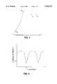
- FIG. 1illustrates a situation where a deep fade can occur
- FIG. 2is a graph of signal strength versus distance which illustrates fading for a single transmitting antenna and a single receiving antenna;
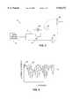
- FIG. 3shows a basic transmitter section illustrative of an embodiment of the present invention
- FIG. 4is a graph of signal strength versus distance between transmitter and receiver when substantially orthogonally polarized signals and time varying offsets are used in accordance with the present invention
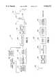
- FIG. 5shows a further transmitter section according to the present invention
- FIG. 6shows a receiver section to be used with the FIG. 5 transmitter section of the present invention
- FIG. 7shows a spatially diverse transmitter section in accordance with the present invention.
- FIG. 8shows a receiver section which includes two antennas for receiving two substantially orthogonally polarized signals in accordance with a further embodiment of the present invention.
- FIG. 1illustrates a situation where deep fading can occur.
- phasors S 1 and S 2represent the received signals from two transmitting antennas T 1 and T 2 , respectively.
- destructive addition of the phasors S 1 and S 2results in a deep fade which can be compensated by the present invention.
- FIG. 2is a graph of signal strength versus distance for a single transmitting and a single receiving antenna. It illustrates fading in a different way than FIG. 1.
- the received signal strength yvaries with the distance x of the receiver from the transmitter.
- the received signalis below a signal strength y 1 , where signal strength y 1 is one below which data reception may be compromised.
- signal strength y 1is one below which data reception may be compromised.
- the deep fademay be observed for an unacceptably long time.
- Such fadingmay be characterized as slow fading.
- the present inventionreduces the problems arising from slow fading by inducing rapid fading which may be suitably compensated for.
- the transmitter section 10includes a data signal source 20, channels 21 and 22, and an oscillator 26, which applies a time varying phase offset, a mixer 24, and two transmitting antennas 30 and 32.
- the data signal source 20provides a data signal "D", such as a digital audio broadcast signal, to the inputs of both of the channels 21 and 22.
- the signal Dis carried by the channels 21 and 22 to the antennas 30 and 32, respectively.
- the mixer 24 and oscillator 26time vary the transmit phase of the signal transmitted from the antenna 30.
- the rate of variation of the antenna polarizationshould be about 1-2% of the data symbol rate.
- a time varying phase offset corresponding to a fixed frequency offset of about 1-2% of the data symbol ratemay be used. Therefore, a time varying phase offset which results in a fixed frequency offset of about 3-6 kHz, for audio broadcasting may be used.
- the antennas 30 and 32are linear antennas which are configured to transmit substantially orthogonally polarized signals.
- Antenna 30transmits a linearly polarized signal in the vertical plane, while antenna 32 transmits a linearly polarized signal in the horizontal plane.
- the receiving antenna 35receives the combined transmitted signals, after transmission through multiple paths, and after modification by noise, delay, and distortion.
- FIG. 4graphically illustrates the rapid fading characteristics created by the present invention.
- the solid envelope curve 30'shows the signal strength which might be observed at a receiver due to the signal transmitted from a single antenna 30.
- the dashed envelope curve 32'shows the signal strength which might be observed due to the signal transmitted from a single antenna 32.
- the curve 31 between the envelopesillustrates the resulting rapid fading signal which might be received by receiver 35 from transmitter 10 with the substantially orthogonally polarized signals transmitted from antennas 30 and 32 with time varying offset applied to the signal transmitted by antenna 30. It should be recognized that FIG. 4 is illustrative only and that the rapid fading signal curve 31 may at times exceed the bounds of the two single antenna signal envelopes 30', 32'. Furthermore, the signal strength will vary even at a fixed distance.
- FIG. 5shows a transmitter 100 according to the present invention.
- the transmitter 100includes a digital signal source 120, which includes a message signal source 134, a channel encoder 136, and an interleaver 138.
- Transmitter 100further includes a carrier signal source 142, a modulator 144 with first and second inputs, an RF filter and amplifier section 146, channel 121 which includes mixer 124 and oscillator 126, channel 122, and orthogonally polarized transmitting antennas 130 and 132.
- Message signal source 134provides a digital data signal D m to the channel encoder 136.
- Channel encoder 136applies an error control coding technique to the signal D m (or a "channel coding" technique) and outputs a signal D e .
- the error control coding technique applied by channel encoder 136may be block coding or convolutional coding.
- the input data rate to the channel encoderis in the range of about 300 kbits/second.
- the interleaveris a block interleaver and the modulation scheme is 4-PSK. Additional induced channel variations are introduced by small carrier frequency offsets using mixer 124 and oscillator 126.
- f 1is the carrier frequency transmitted from antenna 130.
- f 1f c + ⁇ f.
- f cis the carrier frequency of the signal transmitted by antenna 132
- ⁇ fis the frequency offset at transmitting antenna 130.
- This fixed frequency offsetcan be typically in the range of 1-2% of the data symbol rate.
- the frequency offsetmay be applied to the baseband data stream before it is sent to the RF unit and the antenna.
- a 200 millisecond delay or duration for interleavingis an appropriate duration for digital audio broadcasting applications.
- the interleaver 138is provided to rearrange the data of the signal D e in a pseudorandom fashion.
- the output of interleaver 138, a signal D iis provided as an input to the second input of the modulator 144.
- a second signal, carrier signal Cis provided as an input to the first input of modulator 144.
- a modulated carrier signal C mis produced at the output of the modulator 144.
- the modulation technique usedis preferably phase shift keying (PSK), although other modulation techniques such as amplitude shift keying (ASK) and frequency shift keying (FSK) can be used with a digital data source.
- PSKphase shift keying
- ASKamplitude shift keying
- FSKfrequency shift keying
- the modulatorcan be coherent or employ differential encoding. Coherent modulation, such as PSK, is preferred because an equalizer is preferably used in the receiver. However, differential encoding such as differential phase shift keying can be used.
- the signal C mis input to the RF filter and amplifier section 146.
- filtersshape the spectrum of modulated carrier signal C m and amplifiers increase the signal strength to an appropriate level for transmission.
- a filtered and amplified signal C fis produced at the output of the RF filter and amplifier section 146 and applied to the inputs of the two channels, 121 and 122.
- the signal C fis thus input to both antenna 132 and mixer 124.
- the oscillator 126 and mixer 124apply a time varying phase offset, Off a (t) to the signal C f applied to an input of the mixer 124.
- the offset signal C ais the resultant output signal from the mixer 124.
- the signals C a and C fare applied for transmission to the antennas 130 and 132, respectively.
- the antennas 130 and 132are preferably helical antennas. With this arrangement, the antenna 130 transmits a right hand circularly polarized signal and antenna 132 transmits a left hand circularly polarized signal.
- FIG. 6illustrates a receiver section 200 which is suitable for use with the transmitter 100 of FIG. 5.
- the receiver section 200includes a receiving antenna 235, an RF filter and amplifier section 202, a demodulator 204, an equalizer 206, a deinterleaver 208, and a channel decoder 210.
- the antenna 235receives a combined signal consisting of the addition of the signals C a and C f , after their transmission through various multipaths, and after modification by noise, delay, and distortion.
- the received signalbecomes the input of the RF filter and amplifier section 202.
- RF filtersreduce noise and amplifiers increase the received signal strength.
- the output of the RF filter and amplifier section 202is then applied to the demodulator 204 which demodulates the signal.
- the output of demodulator 204is applied to the equalizer 206 which helps to reduce any amplitude and delay distortion.
- Equalizer 206 in FIG. 6can be a decision-feedback type.
- the output of equalizer 206is applied to the deinterleaver 208 which is used to rearrange data symbols to undo the process of interleaving which occurred in the interleaver 138 in the transmitter 100.
- the output of the deinterleaver 208is applied to a channel decoder 210 which derives the original data message signal, and produces that signal at its output.
- time varying amplitude or other time-varying phase offsetscan also be used.
- the time varying offsetsmay be continuous or may take on discrete values as a function of time.
- Time varying offsetscan be applied by mechanically moving one of the antennas or preferably by circuits known in the art which electronically apply time varying phase or amplitude offsets to an input signal.
- an input signalcan be applied to first input of a mixer, such as mixer 124, whose second input is a low frequency signal from an oscillator, such as oscillator 126, as shown in FIG. 5.
- the low frequency signalapplies a time varying phase offset (which in this case is the same as a fixed frequency offset) to the input signal.
- the time varying offsets introduced to the transmitting antenna signalsshould not be large enough to cause erroneous data transmission.
- time diversity of fadingimproves with faster offsets at the transmit antennas.
- the offsetsvary at a rate which is between 1 to 2% of the data rate, for example, a 3-6 kHz rate for 300 ksymbols/sec DAB transmission system. This is small in comparison to the data rate but large enough to cause sufficient time diversity.
- antennas in accordance with the present inventionbe configured to create vertically/horizontally polarized or left/right hand circularly polarized signals. These polarizations create signals which have fading that is highly uncorrelated at the receive antennas.
- a carrier signal source in accordance with the present inventionpreferably produces a sinusoidal signal and may operate at a frequency of about 100 MHz for applications such as FM digital audio broadcasting.
- the transmitter 300includes a signal source 302, channels 304, 306, 308, and 310, mixers 312, 314, and 316, transmitting antennas 320, 322, 324, 326, and oscillators 332, 334, and 336.
- a signal Sis output from the signal source 302 and is applied to the inputs of each of the channels 304, 306, 308, and 310.
- Each oscillatorapplies a different time varying phase offset through its corresponding mixer.
- Each oscillator frequencyis different and each is independent of the signal from the respective channel. Offset signals are produced at the outputs of the mixers 312, 314, and 316, and are applied to the antennas 320, 322, and 324, respectively.
- the antennas 320 and 322are spatially diverse from each other to further reduce the effects of fading.
- the antennas 324 and 326are similarly spatially diverse.
- Antennas 320 and 322are preferably linear antennas which transmit signals with vertical polarization.
- Antennas 324 and 326are preferably linear antennas which transmit signals with horizontal polarization.
- the signal source 302may have components corresponding to the message signal source 134, channel encoder 136, interleaver 138, carrier signal source 142, modulator 144, and RF filters and amplifier section 146, shown in FIG. 5.
- the receiver 400includes two receiving antennas, 424 and 426, mixer 428, an oscillator 432, a signal combiner 434, and a signal processing block 430.
- the antennas 424 and 426are preferably linear antennas. Antenna 424 transmits with vertical polarization and antenna 426 transmits with horizontal polarization. Mixer 428 and oscillator 432 apply a time varying phase offset to the signal received by the antenna 426.
- the signal processing block 430may include elements corresponding to the RF filter and amplifier section 202, demodulator 204, equalizer 206, deinterleaver 208, and channel decoder 210, shown in FIG. 6.
Landscapes
- Engineering & Computer Science (AREA)
- Computer Networks & Wireless Communication (AREA)
- Signal Processing (AREA)
- Radio Transmission System (AREA)
- Digital Transmission Methods That Use Modulated Carrier Waves (AREA)
- Transmission Systems Not Characterized By The Medium Used For Transmission (AREA)
- Cable Transmission Systems, Equalization Of Radio And Reduction Of Echo (AREA)
- Mobile Radio Communication Systems (AREA)
Abstract
Description
Claims (5)
Priority Applications (1)
| Application Number | Priority Date | Filing Date | Title |
|---|---|---|---|
| US08/880,618US5943372A (en) | 1993-11-30 | 1997-06-23 | Orthogonal polarization and time varying offsetting of signals for digital data transmission or reception |
Applications Claiming Priority (3)
| Application Number | Priority Date | Filing Date | Title |
|---|---|---|---|
| US15988093A | 1993-11-30 | 1993-11-30 | |
| US68511296A | 1996-07-23 | 1996-07-23 | |
| US08/880,618US5943372A (en) | 1993-11-30 | 1997-06-23 | Orthogonal polarization and time varying offsetting of signals for digital data transmission or reception |
Related Parent Applications (1)
| Application Number | Title | Priority Date | Filing Date |
|---|---|---|---|
| US68511296AContinuation | 1993-11-30 | 1996-07-23 |
Publications (1)
| Publication Number | Publication Date |
|---|---|
| US5943372Atrue US5943372A (en) | 1999-08-24 |
Family
ID=22574488
Family Applications (1)
| Application Number | Title | Priority Date | Filing Date |
|---|---|---|---|
| US08/880,618Expired - LifetimeUS5943372A (en) | 1993-11-30 | 1997-06-23 | Orthogonal polarization and time varying offsetting of signals for digital data transmission or reception |
Country Status (4)
| Country | Link |
|---|---|
| US (1) | US5943372A (en) |
| EP (1) | EP0656697A3 (en) |
| JP (1) | JP3241954B2 (en) |
| CA (1) | CA2118355C (en) |
Cited By (88)
| Publication number | Priority date | Publication date | Assignee | Title |
|---|---|---|---|---|
| US6026203A (en)* | 1998-07-30 | 2000-02-15 | Hewlett-Packard Company | Polarization mixer based on walk-off crystals, half-wave plates and TEC fibers |
| US6064665A (en)* | 1997-10-22 | 2000-05-16 | U S West, Inc. | System and method for single to two-band personal communication service base station conversion |
| EP0801473A3 (en)* | 1996-04-10 | 2000-08-02 | Lucent Technologies Inc. | Methods and apparatus for high data rate transmission in narrowband mobile radio channels |
| US6188736B1 (en)* | 1997-12-23 | 2001-02-13 | At&T Wireless Svcs. Inc. | Near-optimal low-complexity decoding of space-time codes for fixed wireless applications |
| US20010031018A1 (en)* | 1998-12-31 | 2001-10-18 | Mohammed Nafie | Block level space time transmit diversity in wireless communications |
| US20020015401A1 (en)* | 2000-08-03 | 2002-02-07 | Ravi Subramanian | Flexible TDMA system architecture |
| US20020034264A1 (en)* | 2000-05-25 | 2002-03-21 | Vigil Armando J. | Method for demodulating a digital signal subjected to multipath propagation impairment and an associated receiver |
| US20020034968A1 (en)* | 2000-09-20 | 2002-03-21 | Georg Fischer | Radio system, antenna arrangement and polarization modulator for generating a transmit signal with changing polarization |
| WO2002007371A3 (en)* | 2000-07-14 | 2002-06-13 | At & T Wireless Services Inc | Multicarrier transmission using polarized antennae |
| US20020075840A1 (en)* | 2000-08-31 | 2002-06-20 | Venkatesh Vadde | Envelope stabilization method and apparatus |
| US20020164963A1 (en)* | 2001-04-09 | 2002-11-07 | Tehrani Ardavan Maleki | Method and system for providing antenna diversity |
| US20030021341A1 (en)* | 2000-04-24 | 2003-01-30 | Vigil Armando J. | Method of effective backwards compatible ATSC-DTV multipath equalization through training symbol induction |
| US6542556B1 (en) | 2000-03-31 | 2003-04-01 | Nokia Mobile Phones Ltd. | Space-time code for multiple antenna transmission |
| US20030108087A1 (en)* | 2001-12-06 | 2003-06-12 | Itzhak Shperling | Method and base station for providing transmit diversity |
| US20030109282A1 (en)* | 2001-12-06 | 2003-06-12 | Itzhak Shperling | Method and base station for providing phase-shift transmit diversity |
| US20040042390A1 (en)* | 2002-08-28 | 2004-03-04 | Samel Celebi | Dithering scheme using multiple antennas for OFDM systems |
| US20040104843A1 (en)* | 2002-02-27 | 2004-06-03 | Masahiro Mimura | Polarized wave measuring apparatus, and antenna characteristic measuring apparatus and radio wave measuring apparatus using the same |
| US6775329B2 (en) | 1997-09-16 | 2004-08-10 | At&T Wireless Services, Inc. | Transmitter diversity technique for wireless communications |
| US6807240B2 (en) | 1997-10-31 | 2004-10-19 | At&T Wireless Services, Inc. | Low complexity maximum likelihood detection of concatenate space codes for wireless applications |
| US6826234B1 (en)* | 1999-08-11 | 2004-11-30 | National Institute Of Information And Communications Technology | Radio communication apparatus and radio communication method |
| US20050190689A1 (en)* | 2004-02-26 | 2005-09-01 | Sumantra Chakravarty | Suppressing cross-polarization interference in an orthogonal communication link |
| US20060010473A1 (en)* | 2004-06-25 | 2006-01-12 | Funai Electric Co., Ltd. | Digital television broadcast signal receiver |
| US7065156B1 (en) | 2000-08-31 | 2006-06-20 | Nokia Mobile Phones Ltd. | Hopped delay diversity for multiple antenna transmission |
| US20070072545A1 (en)* | 2001-09-14 | 2007-03-29 | Atc Technologies, Llc | Space-Based Network Architectures for Satellite Radiotelephone Systems |
| US20070111678A1 (en)* | 2000-09-15 | 2007-05-17 | Pramod Viswanath | Methods and apparatus for transmitting information between a basestation and multiple mobile stations |
| US7274752B2 (en) | 1998-09-17 | 2007-09-25 | Cingular Wireless Ii, Llc | Maximum ratio transmission |
| US20070286599A1 (en)* | 2006-06-12 | 2007-12-13 | Michael Sauer | Centralized optical-fiber-based wireless picocellular systems and methods |
| US20070292136A1 (en)* | 2006-06-16 | 2007-12-20 | Michael Sauer | Transponder for a radio-over-fiber optical fiber cable |
| US20080044186A1 (en)* | 2006-08-16 | 2008-02-21 | Jacob George | Radio-over-fiber transponder with a dual-band patch antenna system |
| US20080064335A1 (en)* | 1999-02-16 | 2008-03-13 | Mitsubishi Denki Kabushiki Kaisha | Radio Communication System, a Transmitter and a Receiver |
| US20080070502A1 (en)* | 2006-09-15 | 2008-03-20 | Jacob George | Radio-over-fiber (RoF) optical fiber cable system with transponder diversity and RoF wireless picocellular system using same |
| US20080081566A1 (en)* | 2006-09-29 | 2008-04-03 | Ahmadreza Rofougaran | Method and system for antenna architecture for multi-antenna ofd based systems |
| US20080080863A1 (en)* | 2006-09-28 | 2008-04-03 | Michael Sauer | Radio-over-fiber (RoF) wireless picocellular system with combined picocells |
| US20080240279A1 (en)* | 2004-02-10 | 2008-10-02 | T-Mobile Deutschland Gmbh | Method and Device For Operating Mimo Air Interfaces in Mobile Communications Systems |
| US20110019630A1 (en)* | 2009-07-24 | 2011-01-27 | Raytheon Company | Cross Domain Modulation Scheme for a Wireless Communication Link |
| US20110200325A1 (en)* | 2010-02-15 | 2011-08-18 | Andrey Kobyakov | Dynamic Cell Bonding (DCB) for Radio-over-Fiber (RoF)-Based Networks and Communication Systems and Related Methods |
| US8111998B2 (en) | 2007-02-06 | 2012-02-07 | Corning Cable Systems Llc | Transponder systems and methods for radio-over-fiber (RoF) wireless picocellular systems |
| US8175459B2 (en) | 2007-10-12 | 2012-05-08 | Corning Cable Systems Llc | Hybrid wireless/wired RoF transponder and hybrid RoF communication system using same |
| USRE43812E1 (en) | 1998-11-24 | 2012-11-20 | Linex Technologies, Inc. | Multiple-input multiple-output (MIMO) spread-spectrum system and method |
| US8548330B2 (en) | 2009-07-31 | 2013-10-01 | Corning Cable Systems Llc | Sectorization in distributed antenna systems, and related components and methods |
| US8644844B2 (en) | 2007-12-20 | 2014-02-04 | Corning Mobileaccess Ltd. | Extending outdoor location based services and applications into enclosed areas |
| US8744031B1 (en)* | 2012-12-10 | 2014-06-03 | Electronics And Telecommunications Research Institute | Device and method for estimating carrier frequency offset of OFDM signals transmitted and received through plurality of polarized antennas |
| US20140269449A1 (en)* | 2013-03-15 | 2014-09-18 | Qualcomm Incorporated | Full-duplex wireless transceiver with hybrid circuit and reconfigurable radiation pattern antenna |
| US8867919B2 (en) | 2007-07-24 | 2014-10-21 | Corning Cable Systems Llc | Multi-port accumulator for radio-over-fiber (RoF) wireless picocellular systems |
| US8873585B2 (en) | 2006-12-19 | 2014-10-28 | Corning Optical Communications Wireless Ltd | Distributed antenna system for MIMO technologies |
| US9037143B2 (en) | 2010-08-16 | 2015-05-19 | Corning Optical Communications LLC | Remote antenna clusters and related systems, components, and methods supporting digital data signal propagation between remote antenna units |
| US9042732B2 (en) | 2010-05-02 | 2015-05-26 | Corning Optical Communications LLC | Providing digital data services in optical fiber-based distributed radio frequency (RF) communication systems, and related components and methods |
| US9112611B2 (en) | 2009-02-03 | 2015-08-18 | Corning Optical Communications LLC | Optical fiber-based distributed antenna systems, components, and related methods for calibration thereof |
| US9178635B2 (en) | 2014-01-03 | 2015-11-03 | Corning Optical Communications Wireless Ltd | Separation of communication signal sub-bands in distributed antenna systems (DASs) to reduce interference |
| US9184843B2 (en) | 2011-04-29 | 2015-11-10 | Corning Optical Communications LLC | Determining propagation delay of communications in distributed antenna systems, and related components, systems, and methods |
| US9219879B2 (en) | 2009-11-13 | 2015-12-22 | Corning Optical Communications LLC | Radio-over-fiber (ROF) system for protocol-independent wired and/or wireless communication |
| US9240835B2 (en) | 2011-04-29 | 2016-01-19 | Corning Optical Communications LLC | Systems, methods, and devices for increasing radio frequency (RF) power in distributed antenna systems |
| US9247543B2 (en) | 2013-07-23 | 2016-01-26 | Corning Optical Communications Wireless Ltd | Monitoring non-supported wireless spectrum within coverage areas of distributed antenna systems (DASs) |
| US9258052B2 (en) | 2012-03-30 | 2016-02-09 | Corning Optical Communications LLC | Reducing location-dependent interference in distributed antenna systems operating in multiple-input, multiple-output (MIMO) configuration, and related components, systems, and methods |
| US9325429B2 (en) | 2011-02-21 | 2016-04-26 | Corning Optical Communications LLC | Providing digital data services as electrical signals and radio-frequency (RF) communications over optical fiber in distributed communications systems, and related components and methods |
| US9357551B2 (en) | 2014-05-30 | 2016-05-31 | Corning Optical Communications Wireless Ltd | Systems and methods for simultaneous sampling of serial digital data streams from multiple analog-to-digital converters (ADCS), including in distributed antenna systems |
| US9385810B2 (en) | 2013-09-30 | 2016-07-05 | Corning Optical Communications Wireless Ltd | Connection mapping in distributed communication systems |
| US9420542B2 (en) | 2014-09-25 | 2016-08-16 | Corning Optical Communications Wireless Ltd | System-wide uplink band gain control in a distributed antenna system (DAS), based on per band gain control of remote uplink paths in remote units |
| US9455784B2 (en) | 2012-10-31 | 2016-09-27 | Corning Optical Communications Wireless Ltd | Deployable wireless infrastructures and methods of deploying wireless infrastructures |
| US9525472B2 (en) | 2014-07-30 | 2016-12-20 | Corning Incorporated | Reducing location-dependent destructive interference in distributed antenna systems (DASS) operating in multiple-input, multiple-output (MIMO) configuration, and related components, systems, and methods |
| US9525488B2 (en) | 2010-05-02 | 2016-12-20 | Corning Optical Communications LLC | Digital data services and/or power distribution in optical fiber-based distributed communications systems providing digital data and radio frequency (RF) communications services, and related components and methods |
| US9531452B2 (en) | 2012-11-29 | 2016-12-27 | Corning Optical Communications LLC | Hybrid intra-cell / inter-cell remote unit antenna bonding in multiple-input, multiple-output (MIMO) distributed antenna systems (DASs) |
| US9602210B2 (en) | 2014-09-24 | 2017-03-21 | Corning Optical Communications Wireless Ltd | Flexible head-end chassis supporting automatic identification and interconnection of radio interface modules and optical interface modules in an optical fiber-based distributed antenna system (DAS) |
| US9621293B2 (en) | 2012-08-07 | 2017-04-11 | Corning Optical Communications Wireless Ltd | Distribution of time-division multiplexed (TDM) management services in a distributed antenna system, and related components, systems, and methods |
| US9647758B2 (en) | 2012-11-30 | 2017-05-09 | Corning Optical Communications Wireless Ltd | Cabling connectivity monitoring and verification |
| US9661781B2 (en) | 2013-07-31 | 2017-05-23 | Corning Optical Communications Wireless Ltd | Remote units for distributed communication systems and related installation methods and apparatuses |
| US9673904B2 (en) | 2009-02-03 | 2017-06-06 | Corning Optical Communications LLC | Optical fiber-based distributed antenna systems, components, and related methods for calibration thereof |
| US9681313B2 (en) | 2015-04-15 | 2017-06-13 | Corning Optical Communications Wireless Ltd | Optimizing remote antenna unit performance using an alternative data channel |
| US9715157B2 (en) | 2013-06-12 | 2017-07-25 | Corning Optical Communications Wireless Ltd | Voltage controlled optical directional coupler |
| US9730228B2 (en) | 2014-08-29 | 2017-08-08 | Corning Optical Communications Wireless Ltd | Individualized gain control of remote uplink band paths in a remote unit in a distributed antenna system (DAS), based on combined uplink power level in the remote unit |
| US9729267B2 (en) | 2014-12-11 | 2017-08-08 | Corning Optical Communications Wireless Ltd | Multiplexing two separate optical links with the same wavelength using asymmetric combining and splitting |
| US20170237510A1 (en)* | 2014-08-05 | 2017-08-17 | Institut Fur Rundfunktechnik Gmbh | Variable time offset in a single frequency network transmission system |
| US9775123B2 (en) | 2014-03-28 | 2017-09-26 | Corning Optical Communications Wireless Ltd. | Individualized gain control of uplink paths in remote units in a distributed antenna system (DAS) based on individual remote unit contribution to combined uplink power |
| US9807700B2 (en) | 2015-02-19 | 2017-10-31 | Corning Optical Communications Wireless Ltd | Offsetting unwanted downlink interference signals in an uplink path in a distributed antenna system (DAS) |
| US20180091213A1 (en)* | 2016-09-27 | 2018-03-29 | Nokia Solutions And Networks Oy | Mobile base station receiver digitalization capacity enhancement using combined analog signals |
| US9948349B2 (en) | 2015-07-17 | 2018-04-17 | Corning Optical Communications Wireless Ltd | IOT automation and data collection system |
| US9974074B2 (en) | 2013-06-12 | 2018-05-15 | Corning Optical Communications Wireless Ltd | Time-division duplexing (TDD) in distributed communications systems, including distributed antenna systems (DASs) |
| US10096909B2 (en) | 2014-11-03 | 2018-10-09 | Corning Optical Communications Wireless Ltd. | Multi-band monopole planar antennas configured to facilitate improved radio frequency (RF) isolation in multiple-input multiple-output (MIMO) antenna arrangement |
| US10110308B2 (en) | 2014-12-18 | 2018-10-23 | Corning Optical Communications Wireless Ltd | Digital interface modules (DIMs) for flexibly distributing digital and/or analog communications signals in wide-area analog distributed antenna systems (DASs) |
| US10128951B2 (en) | 2009-02-03 | 2018-11-13 | Corning Optical Communications LLC | Optical fiber-based distributed antenna systems, components, and related methods for monitoring and configuring thereof |
| US10136200B2 (en) | 2012-04-25 | 2018-11-20 | Corning Optical Communications LLC | Distributed antenna system architectures |
| US10135533B2 (en) | 2014-11-13 | 2018-11-20 | Corning Optical Communications Wireless Ltd | Analog distributed antenna systems (DASS) supporting distribution of digital communications signals interfaced from a digital signal source and analog radio frequency (RF) communications signals |
| US10187151B2 (en) | 2014-12-18 | 2019-01-22 | Corning Optical Communications Wireless Ltd | Digital-analog interface modules (DAIMs) for flexibly distributing digital and/or analog communications signals in wide-area analog distributed antenna systems (DASs) |
| US10236924B2 (en) | 2016-03-31 | 2019-03-19 | Corning Optical Communications Wireless Ltd | Reducing out-of-channel noise in a wireless distribution system (WDS) |
| US10560214B2 (en) | 2015-09-28 | 2020-02-11 | Corning Optical Communications LLC | Downlink and uplink communication path switching in a time-division duplex (TDD) distributed antenna system (DAS) |
| US10630510B2 (en) | 2015-04-20 | 2020-04-21 | University Of Notre Dame Du Lac | Space-polarization modulated communications |
| US10659163B2 (en) | 2014-09-25 | 2020-05-19 | Corning Optical Communications LLC | Supporting analog remote antenna units (RAUs) in digital distributed antenna systems (DASs) using analog RAU digital adaptors |
| US11178609B2 (en) | 2010-10-13 | 2021-11-16 | Corning Optical Communications LLC | Power management for remote antenna units in distributed antenna systems |
Families Citing this family (17)
| Publication number | Priority date | Publication date | Assignee | Title |
|---|---|---|---|---|
| SE518016C2 (en)* | 1995-11-10 | 2002-08-13 | Telia Ab | Method and apparatus for reducing fading in mobile radio systems |
| GB2310109B (en)* | 1996-02-08 | 2000-07-05 | Orange Personal Comm Serv Ltd | Antenna arrangement |
| FR2746991B1 (en) | 1996-03-28 | 1998-06-12 | Nortel Matra Cellular | RADIO STATION WITH CIRCULAR POLARIZATION ANTENNAS |
| CN1115006C (en)* | 1997-02-04 | 2003-07-16 | 诺基亚电信股份公司 | Compensation of Doppler shift in mobile communication system |
| US5933421A (en)* | 1997-02-06 | 1999-08-03 | At&T Wireless Services Inc. | Method for frequency division duplex communications |
| IT1295010B1 (en)* | 1997-09-10 | 1999-04-27 | Siae Microelettronica Spa | TELECOMMUNICATION SYSTEM AND METHOD USING RADIO BRIDGES |
| US6181920B1 (en) | 1997-10-20 | 2001-01-30 | Ericsson Inc. | Transmitter that selectively polarizes a radio wave |
| US6324407B1 (en)* | 1999-02-26 | 2001-11-27 | Motorola, Inc. | Method and apparatus for signal transmission within a wireless communication system |
| AU2001213620A1 (en)* | 2000-05-23 | 2001-12-03 | Littlefeet, Inc. | System for reducing fast fading effects in radio communications systems |
| GB2376843B (en)* | 2001-06-18 | 2005-01-12 | Ubinetics Ltd | A transmitter station and a radiotelephone system including a transmitter station |
| RU2227370C2 (en)* | 2002-05-31 | 2004-04-20 | Федеральное Государственное унитарное предприятие Воронежский научно-исследовательский институт связи | Radio link ensuring enhanced hiding of information transferred |
| US7327811B2 (en)* | 2003-04-01 | 2008-02-05 | Telefonaktiebolaget L M Ericsson | Method and apparatus for facilitating signal discrimination in a wireless network by applying known frequency offsets |
| RU2271606C1 (en)* | 2004-11-22 | 2006-03-10 | Федеральное государственное унитарное предприятие "Воронежский научно-исследовательский институт связи" | Radio communication line |
| US7660598B2 (en)* | 2004-12-21 | 2010-02-09 | Qualcomm, Incorporated | Transmit power reduction for a wireless device with multiple transmit signal paths |
| DE102005061219A1 (en)* | 2005-12-20 | 2007-06-21 | Fachhochschule Aachen | Radio transmission line arrangement, has multipliers, mixers, phase comparators, frequency comparators or power detectors that are provided for evaluating two different polarized modes |
| JP4527102B2 (en)* | 2006-12-14 | 2010-08-18 | 日本電信電話株式会社 | Wireless communication system and transmitter |
| EP2270993B1 (en) | 2008-04-21 | 2018-07-11 | Nippon Telegraph and Telephone Corporation | Radio communication system and radio communication method |
Citations (12)
| Publication number | Priority date | Publication date | Assignee | Title |
|---|---|---|---|---|
| US3783385A (en)* | 1972-11-28 | 1974-01-01 | Itt | Digital diversity combiner |
| US3882393A (en)* | 1973-06-04 | 1975-05-06 | Us Navy | Communications system utilizing modulation of the characteristic polarizations of the ionosphere |
| US4383332A (en)* | 1980-11-21 | 1983-05-10 | Bell Telephone Laboratories, Incorporated | High capacity digital mobile radio system |
| US4490830A (en)* | 1981-07-22 | 1984-12-25 | Nippon Electric Co., Ltd. | Radio signal transmission system including a plurality of transmitters for transmitting a common signal |
| US4521878A (en)* | 1982-01-28 | 1985-06-04 | Fujitsu Limited | Data transmitting-receiving system |
| US4601046A (en)* | 1984-05-15 | 1986-07-15 | Halpern Peter H | System for transmitting data through a troposcatter medium |
| US4727534A (en)* | 1986-08-19 | 1988-02-23 | American Telephone And Telegraph Company | Timing and carrier recovery in dual polarization communications systems |
| US4905084A (en)* | 1989-01-30 | 1990-02-27 | Carole Broadcasting Technologies, Inc. | Compatible and spectrum efficient high definition television |
| US5280631A (en)* | 1988-06-15 | 1994-01-18 | Matsushita Electric Works, Ltd. | Polarization diversity system suitable for radio communication in indoor space |
| US5305353A (en)* | 1992-05-29 | 1994-04-19 | At&T Bell Laboratories | Method and apparatus for providing time diversity |
| US5369800A (en)* | 1991-08-16 | 1994-11-29 | Small Power Communication Systems Research Laboratories Co., Ltd. | Multi-frequency communication system with an improved diversity scheme |
| US5377035A (en)* | 1993-09-28 | 1994-12-27 | Hughes Aircraft Company | Wavelength division multiplexed fiber optic link for RF polarization diversity receiver |
Family Cites Families (2)
| Publication number | Priority date | Publication date | Assignee | Title |
|---|---|---|---|---|
| US4160952A (en)* | 1978-05-12 | 1979-07-10 | Bell Telephone Laboratories, Incorporated | Space diversity receiver with combined step and continuous phase control |
| JPS59104847A (en)* | 1982-12-07 | 1984-06-16 | Fujitsu Ltd | Radio communicating system |
- 1994
- 1994-10-18CACA002118355Apatent/CA2118355C/ennot_activeExpired - Fee Related
- 1994-11-23EPEP94308644Apatent/EP0656697A3/ennot_activeWithdrawn
- 1994-11-28JPJP31602594Apatent/JP3241954B2/ennot_activeExpired - Fee Related
- 1997
- 1997-06-23USUS08/880,618patent/US5943372A/ennot_activeExpired - Lifetime
Patent Citations (12)
| Publication number | Priority date | Publication date | Assignee | Title |
|---|---|---|---|---|
| US3783385A (en)* | 1972-11-28 | 1974-01-01 | Itt | Digital diversity combiner |
| US3882393A (en)* | 1973-06-04 | 1975-05-06 | Us Navy | Communications system utilizing modulation of the characteristic polarizations of the ionosphere |
| US4383332A (en)* | 1980-11-21 | 1983-05-10 | Bell Telephone Laboratories, Incorporated | High capacity digital mobile radio system |
| US4490830A (en)* | 1981-07-22 | 1984-12-25 | Nippon Electric Co., Ltd. | Radio signal transmission system including a plurality of transmitters for transmitting a common signal |
| US4521878A (en)* | 1982-01-28 | 1985-06-04 | Fujitsu Limited | Data transmitting-receiving system |
| US4601046A (en)* | 1984-05-15 | 1986-07-15 | Halpern Peter H | System for transmitting data through a troposcatter medium |
| US4727534A (en)* | 1986-08-19 | 1988-02-23 | American Telephone And Telegraph Company | Timing and carrier recovery in dual polarization communications systems |
| US5280631A (en)* | 1988-06-15 | 1994-01-18 | Matsushita Electric Works, Ltd. | Polarization diversity system suitable for radio communication in indoor space |
| US4905084A (en)* | 1989-01-30 | 1990-02-27 | Carole Broadcasting Technologies, Inc. | Compatible and spectrum efficient high definition television |
| US5369800A (en)* | 1991-08-16 | 1994-11-29 | Small Power Communication Systems Research Laboratories Co., Ltd. | Multi-frequency communication system with an improved diversity scheme |
| US5305353A (en)* | 1992-05-29 | 1994-04-19 | At&T Bell Laboratories | Method and apparatus for providing time diversity |
| US5377035A (en)* | 1993-09-28 | 1994-12-27 | Hughes Aircraft Company | Wavelength division multiplexed fiber optic link for RF polarization diversity receiver |
Non-Patent Citations (8)
| Title |
|---|
| "Andrew Catalog 34", Systems Planning Product Specifications Services, p. 188, 190, 197. |
| Andrew Catalog 34 , Systems Planning Product Specifications Services , p. 188, 190, 197.* |
| Hiroike, "Combined Effects of Phase Sweeping Transmitter Diversity and Channel Coding", IEEE Transactions on Vehicular Technology, vol. 41, No. 2, May 1992. |
| Hiroike, Combined Effects of Phase Sweeping Transmitter Diversity and Channel Coding , IEEE Transactions on Vehicular Technology , vol. 41, No. 2, May 1992.* |
| Iwai, A Fading Reduction Technique Using Interleave Aided Open Loop Space Diversity for Digital Maritime Satellite Communications, IEICE Transactions , vol. E 74, No. 10 Oct. 1991.* |
| Iwai, A Fading Reduction Technique Using Interleave-Aided Open Loop Space Diversity for Digital Maritime-Satellite Communications, IEICE Transactions, vol. E 74, No. 10 Oct. 1991. |
| Winters, J., "Optimum Combining in Digital Mobile Radio with Co-Channel Interference", reprinted from IEEE International Conference on Communications, ICC '83, Jun. 19-22, 1983, IEEE. |
| Winters, J., Optimum Combining in Digital Mobile Radio with Co Channel Interference , reprinted from IEEE International Conference on Communications, ICC 83, Jun. 19 22, 1983, IEEE.* |
Cited By (192)
| Publication number | Priority date | Publication date | Assignee | Title |
|---|---|---|---|---|
| EP0801473A3 (en)* | 1996-04-10 | 2000-08-02 | Lucent Technologies Inc. | Methods and apparatus for high data rate transmission in narrowband mobile radio channels |
| US20110170635A1 (en)* | 1997-09-16 | 2011-07-14 | Siavash Alamouti | Transmitter diversity technique for wireless communications |
| US9203499B2 (en) | 1997-09-16 | 2015-12-01 | At&T Mobility Ii Llc | Transmitter diversity technique for wireless communications |
| US9749032B2 (en) | 1997-09-16 | 2017-08-29 | At&T Mobility Ii Llc | Transmitter diversity technique for wireless communications |
| US8355475B2 (en) | 1997-09-16 | 2013-01-15 | At&T Mobility Ii Llc | Diversity technique for wireless communications |
| US6775329B2 (en) | 1997-09-16 | 2004-08-10 | At&T Wireless Services, Inc. | Transmitter diversity technique for wireless communications |
| US7916806B2 (en) | 1997-09-16 | 2011-03-29 | At&T Mobility Ii Llc | Transmitter diversity technique for wireless communications |
| US7587007B2 (en) | 1997-09-16 | 2009-09-08 | At&T Mobility Ii Llc | Transmitter diversity technique for wireless communications |
| US7386077B2 (en) | 1997-09-16 | 2008-06-10 | At&T Mobility Ii Llc | Receiver diversity technique for wireless communications |
| US20080063107A1 (en)* | 1997-09-16 | 2008-03-13 | At&T Mobility Ii Llc | Transmitter diversity technique for wireless communications |
| US20080008275A1 (en)* | 1997-09-16 | 2008-01-10 | Cingular Wireless Ii, Llc | Transmitter diversity technique for wireless communications |
| US20070110179A1 (en)* | 1997-09-16 | 2007-05-17 | Cingular Wireless Ii, Llc | Transmitter diversity technique for wireless communications |
| US7120200B2 (en) | 1997-09-16 | 2006-10-10 | Cingular Wireless Ii, Llc | Transmitter diversity technique for wireless communications |
| US6064665A (en)* | 1997-10-22 | 2000-05-16 | U S West, Inc. | System and method for single to two-band personal communication service base station conversion |
| US20050105630A1 (en)* | 1997-10-31 | 2005-05-19 | Siavash Alamouti | Low complexity maximum likelihood detection of concatenate space codes for wireless applications |
| US9065516B2 (en) | 1997-10-31 | 2015-06-23 | At&T Mobility Ii, Llc | Low complexity maximum likelihood detection of concatenated space codes for wireless applications |
| US8351545B2 (en) | 1997-10-31 | 2013-01-08 | At&T Mobility Ii Llc | Low complexity maximum likelihood detection of concatenated space codes for wireless applications |
| US8731107B2 (en) | 1997-10-31 | 2014-05-20 | At&T Mobility Ii Llc | Low complexity maximum likelihood detection of concatenated space codes for wireless applications |
| US6853688B2 (en) | 1997-10-31 | 2005-02-08 | Cingular Wireless Ii, Llc | Low complexity maximum likelihood detection of concatenated space codes for wireless applications |
| US7643568B2 (en) | 1997-10-31 | 2010-01-05 | At&T Mobility Ii Llc | Low complexity maximum likelihood detection of concatenated space codes for wireless applications |
| US6807240B2 (en) | 1997-10-31 | 2004-10-19 | At&T Wireless Services, Inc. | Low complexity maximum likelihood detection of concatenate space codes for wireless applications |
| US20090180569A1 (en)* | 1997-12-23 | 2009-07-16 | Titus Lo | Near-Optimal Low-Complexity Decoding of Space-Time Codes for Fixed Wireless Applications |
| US20040203547A1 (en)* | 1997-12-23 | 2004-10-14 | Titus Lo | Near-optimal low-complexity decoding of space-time codes for fixed wireless applications |
| US6741635B2 (en) | 1997-12-23 | 2004-05-25 | At&T Wireless Services, Inc. | Near-optimal low-complexity decoding of space-time codes for fixed wireless applications |
| US7526040B2 (en) | 1997-12-23 | 2009-04-28 | At&T Mobility Ii Llc | Near-optimal low-complexity decoding of space-time codes for fixed wireless applications |
| US7046737B2 (en) | 1997-12-23 | 2006-05-16 | Cingular Wireless Ii, Llc | Near-optimal low-complexity decoding of space-time codes for wireless applications |
| US6470043B1 (en)* | 1997-12-23 | 2002-10-22 | At&T Wireless Services, Inc. | Near-optimal low-complexity decoding of space-time codes for fixed wireless applications |
| US8179991B2 (en) | 1997-12-23 | 2012-05-15 | At&T Mobility Ii Llc | Near-optimal low-complexity decoding of space-time codes for fixed wireless applications |
| US6188736B1 (en)* | 1997-12-23 | 2001-02-13 | At&T Wireless Svcs. Inc. | Near-optimal low-complexity decoding of space-time codes for fixed wireless applications |
| US6026203A (en)* | 1998-07-30 | 2000-02-15 | Hewlett-Packard Company | Polarization mixer based on walk-off crystals, half-wave plates and TEC fibers |
| AU748150B2 (en)* | 1998-07-30 | 2002-05-30 | Avago Technologies General Ip (Singapore) Pte. Ltd. | Polarization mixer based on walk-off crystals, half-wave plates and tec fibers |
| US20070242774A1 (en)* | 1998-09-17 | 2007-10-18 | Cingular Wireless Ii, Llc | Maximum ratio transmission |
| US8520746B2 (en) | 1998-09-17 | 2013-08-27 | At&T Mobility Ii Llc | Maximum ratio transmission |
| US7362823B2 (en) | 1998-09-17 | 2008-04-22 | Cingular Wireless Ii, Llc | Maximum ratio transmission |
| US20080144739A1 (en)* | 1998-09-17 | 2008-06-19 | At&T Mobility Ii Llc | Maximum ratio transmission |
| US7609771B2 (en) | 1998-09-17 | 2009-10-27 | At&T Mobility Ii Llc | Maximum ratio transmission |
| US7274752B2 (en) | 1998-09-17 | 2007-09-25 | Cingular Wireless Ii, Llc | Maximum ratio transmission |
| USRE43812E1 (en) | 1998-11-24 | 2012-11-20 | Linex Technologies, Inc. | Multiple-input multiple-output (MIMO) spread-spectrum system and method |
| US7088785B2 (en)* | 1998-12-31 | 2006-08-08 | Texas Instruments Incorporated | Block level space time transmit diversity in wireless communications |
| US20050058216A9 (en)* | 1998-12-31 | 2005-03-17 | Mohammed Nafie | Block level space time transmit diversity in wireless communications |
| US20010031018A1 (en)* | 1998-12-31 | 2001-10-18 | Mohammed Nafie | Block level space time transmit diversity in wireless communications |
| US20080064335A1 (en)* | 1999-02-16 | 2008-03-13 | Mitsubishi Denki Kabushiki Kaisha | Radio Communication System, a Transmitter and a Receiver |
| US8027649B2 (en)* | 1999-02-16 | 2011-09-27 | Mitsubishi Denki Kabushiki Kaisha | Radio communication system, a transmitter and a receiver |
| US6826234B1 (en)* | 1999-08-11 | 2004-11-30 | National Institute Of Information And Communications Technology | Radio communication apparatus and radio communication method |
| US6542556B1 (en) | 2000-03-31 | 2003-04-01 | Nokia Mobile Phones Ltd. | Space-time code for multiple antenna transmission |
| US20030021341A1 (en)* | 2000-04-24 | 2003-01-30 | Vigil Armando J. | Method of effective backwards compatible ATSC-DTV multipath equalization through training symbol induction |
| US7215719B2 (en) | 2000-05-25 | 2007-05-08 | Vigil Armando J | Method for demodulating a digital signal based on an estimate of a symbol of the digital signal, and an associated receiver |
| US7006581B2 (en) | 2000-05-25 | 2006-02-28 | Vigil Armando J | Method for demodulating a digital signal subjected to multipath propagation impairment and an associated receiver |
| US20020034264A1 (en)* | 2000-05-25 | 2002-03-21 | Vigil Armando J. | Method for demodulating a digital signal subjected to multipath propagation impairment and an associated receiver |
| US7477705B2 (en) | 2000-05-25 | 2009-01-13 | Vigil Armando J | Method for demodulating a digital signal based on an estimate of multipath propagation impairment, and an associated receiver |
| US20060088128A1 (en)* | 2000-05-25 | 2006-04-27 | Vigil Armando J | Method for demodulating a digital signal based on a generated error signal, and an associated receiver |
| US20060088132A1 (en)* | 2000-05-25 | 2006-04-27 | Vigil Armando J | Method for demodulating a digital signal based on an estimate of a symbol of the digital signal, and an associated receiver |
| US7187726B2 (en) | 2000-05-25 | 2007-03-06 | Vigil Armando J | Method for demodulating a digital signal based on a generated error signal, and an associated receiver |
| WO2002007371A3 (en)* | 2000-07-14 | 2002-06-13 | At & T Wireless Services Inc | Multicarrier transmission using polarized antennae |
| US20020015401A1 (en)* | 2000-08-03 | 2002-02-07 | Ravi Subramanian | Flexible TDMA system architecture |
| US7126998B2 (en) | 2000-08-31 | 2006-10-24 | Nokia Mobile Phones Limited | Envelope stabilization method and apparatus |
| US20020075840A1 (en)* | 2000-08-31 | 2002-06-20 | Venkatesh Vadde | Envelope stabilization method and apparatus |
| US7003025B2 (en)* | 2000-08-31 | 2006-02-21 | Nokia Mobile Phones Ltd. | Envelope stabilization method and apparatus |
| US20060067414A1 (en)* | 2000-08-31 | 2006-03-30 | Venkatesh Vadde | Envelope stabilization method and apparatus |
| US7065156B1 (en) | 2000-08-31 | 2006-06-20 | Nokia Mobile Phones Ltd. | Hopped delay diversity for multiple antenna transmission |
| US8023904B2 (en)* | 2000-09-15 | 2011-09-20 | Qualcomm Incorporated | Methods and apparatus for transmitting information between a basestation and multiple mobile stations |
| US20070111678A1 (en)* | 2000-09-15 | 2007-05-17 | Pramod Viswanath | Methods and apparatus for transmitting information between a basestation and multiple mobile stations |
| US20020034968A1 (en)* | 2000-09-20 | 2002-03-21 | Georg Fischer | Radio system, antenna arrangement and polarization modulator for generating a transmit signal with changing polarization |
| EP1191710A1 (en)* | 2000-09-20 | 2002-03-27 | Lucent Technologies Inc. | Radio system, antenna arrangement and polarization modulator for generating a transmit signal with changing polarization |
| US7003323B2 (en) | 2000-09-20 | 2006-02-21 | Lucent Technologies Inc. | Radio system, antenna arrangement and polarization modulator for generating a transmit signal with changing polarization |
| US6961545B2 (en) | 2001-04-09 | 2005-11-01 | Atheros Communications, Inc. | Method and system for providing antenna diversity |
| US20020164963A1 (en)* | 2001-04-09 | 2002-11-07 | Tehrani Ardavan Maleki | Method and system for providing antenna diversity |
| US20070072545A1 (en)* | 2001-09-14 | 2007-03-29 | Atc Technologies, Llc | Space-Based Network Architectures for Satellite Radiotelephone Systems |
| US20030108087A1 (en)* | 2001-12-06 | 2003-06-12 | Itzhak Shperling | Method and base station for providing transmit diversity |
| US20030109282A1 (en)* | 2001-12-06 | 2003-06-12 | Itzhak Shperling | Method and base station for providing phase-shift transmit diversity |
| US7315728B2 (en)* | 2002-02-27 | 2008-01-01 | Matsushita Electric Industrial Co., Ltd. | Polarized wave measuring apparatus, and antenna characteristic measuring apparatus and radio wave measuring apparatus using the same |
| US20040104843A1 (en)* | 2002-02-27 | 2004-06-03 | Masahiro Mimura | Polarized wave measuring apparatus, and antenna characteristic measuring apparatus and radio wave measuring apparatus using the same |
| US20040042390A1 (en)* | 2002-08-28 | 2004-03-04 | Samel Celebi | Dithering scheme using multiple antennas for OFDM systems |
| US8331217B2 (en) | 2002-08-28 | 2012-12-11 | Agere Systems Llc | Dithering scheme using multiple antennas for OFDM systems |
| US20090180564A1 (en)* | 2002-08-28 | 2009-07-16 | Agere Systems Inc. | Dithering scheme using multiple antennas for ofdm systems |
| US7529177B2 (en) | 2002-08-28 | 2009-05-05 | Agere Systems Inc. | Dithering scheme using multiple antennas for OFDM systems |
| US8059742B2 (en) | 2004-02-10 | 2011-11-15 | T-Mobile Deutschland Gmbh | Method and device for operating MIMO air interfaces in mobile communications systems |
| US20080240279A1 (en)* | 2004-02-10 | 2008-10-02 | T-Mobile Deutschland Gmbh | Method and Device For Operating Mimo Air Interfaces in Mobile Communications Systems |
| US8325591B2 (en)* | 2004-02-26 | 2012-12-04 | Qualcomm Incorporated | Suppressing cross-polarization interference in an orthogonal communication link |
| US20050190689A1 (en)* | 2004-02-26 | 2005-09-01 | Sumantra Chakravarty | Suppressing cross-polarization interference in an orthogonal communication link |
| US20060010473A1 (en)* | 2004-06-25 | 2006-01-12 | Funai Electric Co., Ltd. | Digital television broadcast signal receiver |
| US7509666B2 (en)* | 2004-06-25 | 2009-03-24 | Funai Electric Co., Ltd. | Digital television broadcast signal receiver |
| US20070286599A1 (en)* | 2006-06-12 | 2007-12-13 | Michael Sauer | Centralized optical-fiber-based wireless picocellular systems and methods |
| US7590354B2 (en) | 2006-06-16 | 2009-09-15 | Corning Cable Systems Llc | Redundant transponder array for a radio-over-fiber optical fiber cable |
| US20070292136A1 (en)* | 2006-06-16 | 2007-12-20 | Michael Sauer | Transponder for a radio-over-fiber optical fiber cable |
| US7627250B2 (en) | 2006-08-16 | 2009-12-01 | Corning Cable Systems Llc | Radio-over-fiber transponder with a dual-band patch antenna system |
| US20080044186A1 (en)* | 2006-08-16 | 2008-02-21 | Jacob George | Radio-over-fiber transponder with a dual-band patch antenna system |
| WO2008033298A3 (en)* | 2006-09-15 | 2008-05-08 | Corning Cable Sys Llc | Radio over optical fiber cable system with transponder diversity |
| US20080070502A1 (en)* | 2006-09-15 | 2008-03-20 | Jacob George | Radio-over-fiber (RoF) optical fiber cable system with transponder diversity and RoF wireless picocellular system using same |
| US7787823B2 (en) | 2006-09-15 | 2010-08-31 | Corning Cable Systems Llc | Radio-over-fiber (RoF) optical fiber cable system with transponder diversity and RoF wireless picocellular system using same |
| US20080080863A1 (en)* | 2006-09-28 | 2008-04-03 | Michael Sauer | Radio-over-fiber (RoF) wireless picocellular system with combined picocells |
| US7848654B2 (en) | 2006-09-28 | 2010-12-07 | Corning Cable Systems Llc | Radio-over-fiber (RoF) wireless picocellular system with combined picocells |
| US8099131B2 (en)* | 2006-09-29 | 2012-01-17 | Broadcom Corporation | Method and system for antenna architecture for multi-antenna OFD based systems |
| US20080081566A1 (en)* | 2006-09-29 | 2008-04-03 | Ahmadreza Rofougaran | Method and system for antenna architecture for multi-antenna ofd based systems |
| US9130613B2 (en) | 2006-12-19 | 2015-09-08 | Corning Optical Communications Wireless Ltd | Distributed antenna system for MIMO technologies |
| US8873585B2 (en) | 2006-12-19 | 2014-10-28 | Corning Optical Communications Wireless Ltd | Distributed antenna system for MIMO technologies |
| US8111998B2 (en) | 2007-02-06 | 2012-02-07 | Corning Cable Systems Llc | Transponder systems and methods for radio-over-fiber (RoF) wireless picocellular systems |
| US8867919B2 (en) | 2007-07-24 | 2014-10-21 | Corning Cable Systems Llc | Multi-port accumulator for radio-over-fiber (RoF) wireless picocellular systems |
| US8175459B2 (en) | 2007-10-12 | 2012-05-08 | Corning Cable Systems Llc | Hybrid wireless/wired RoF transponder and hybrid RoF communication system using same |
| US8718478B2 (en) | 2007-10-12 | 2014-05-06 | Corning Cable Systems Llc | Hybrid wireless/wired RoF transponder and hybrid RoF communication system using same |
| US8644844B2 (en) | 2007-12-20 | 2014-02-04 | Corning Mobileaccess Ltd. | Extending outdoor location based services and applications into enclosed areas |
| US10153841B2 (en) | 2009-02-03 | 2018-12-11 | Corning Optical Communications LLC | Optical fiber-based distributed antenna systems, components, and related methods for calibration thereof |
| US9673904B2 (en) | 2009-02-03 | 2017-06-06 | Corning Optical Communications LLC | Optical fiber-based distributed antenna systems, components, and related methods for calibration thereof |
| US10128951B2 (en) | 2009-02-03 | 2018-11-13 | Corning Optical Communications LLC | Optical fiber-based distributed antenna systems, components, and related methods for monitoring and configuring thereof |
| US9900097B2 (en) | 2009-02-03 | 2018-02-20 | Corning Optical Communications LLC | Optical fiber-based distributed antenna systems, components, and related methods for calibration thereof |
| US9112611B2 (en) | 2009-02-03 | 2015-08-18 | Corning Optical Communications LLC | Optical fiber-based distributed antenna systems, components, and related methods for calibration thereof |
| US8537657B2 (en)* | 2009-07-24 | 2013-09-17 | Raytheon Company | Cross domain modulation scheme for a wireless communication link |
| US20110019630A1 (en)* | 2009-07-24 | 2011-01-27 | Raytheon Company | Cross Domain Modulation Scheme for a Wireless Communication Link |
| US8548330B2 (en) | 2009-07-31 | 2013-10-01 | Corning Cable Systems Llc | Sectorization in distributed antenna systems, and related components and methods |
| US9219879B2 (en) | 2009-11-13 | 2015-12-22 | Corning Optical Communications LLC | Radio-over-fiber (ROF) system for protocol-independent wired and/or wireless communication |
| US9485022B2 (en) | 2009-11-13 | 2016-11-01 | Corning Optical Communications LLC | Radio-over-fiber (ROF) system for protocol-independent wired and/or wireless communication |
| US9729238B2 (en) | 2009-11-13 | 2017-08-08 | Corning Optical Communications LLC | Radio-over-fiber (ROF) system for protocol-independent wired and/or wireless communication |
| US20110200325A1 (en)* | 2010-02-15 | 2011-08-18 | Andrey Kobyakov | Dynamic Cell Bonding (DCB) for Radio-over-Fiber (RoF)-Based Networks and Communication Systems and Related Methods |
| US9319138B2 (en) | 2010-02-15 | 2016-04-19 | Corning Optical Communications LLC | Dynamic cell bonding (DCB) for radio-over-fiber (RoF)-based networks and communication systems and related methods |
| US8831428B2 (en) | 2010-02-15 | 2014-09-09 | Corning Optical Communications LLC | Dynamic cell bonding (DCB) for radio-over-fiber (RoF)-based networks and communication systems and related methods |
| US8275265B2 (en) | 2010-02-15 | 2012-09-25 | Corning Cable Systems Llc | Dynamic cell bonding (DCB) for radio-over-fiber (RoF)-based networks and communication systems and related methods |
| US9853732B2 (en) | 2010-05-02 | 2017-12-26 | Corning Optical Communications LLC | Digital data services and/or power distribution in optical fiber-based distributed communications systems providing digital data and radio frequency (RF) communications services, and related components and methods |
| US9270374B2 (en) | 2010-05-02 | 2016-02-23 | Corning Optical Communications LLC | Providing digital data services in optical fiber-based distributed radio frequency (RF) communications systems, and related components and methods |
| US9525488B2 (en) | 2010-05-02 | 2016-12-20 | Corning Optical Communications LLC | Digital data services and/or power distribution in optical fiber-based distributed communications systems providing digital data and radio frequency (RF) communications services, and related components and methods |
| US9042732B2 (en) | 2010-05-02 | 2015-05-26 | Corning Optical Communications LLC | Providing digital data services in optical fiber-based distributed radio frequency (RF) communication systems, and related components and methods |
| US9037143B2 (en) | 2010-08-16 | 2015-05-19 | Corning Optical Communications LLC | Remote antenna clusters and related systems, components, and methods supporting digital data signal propagation between remote antenna units |
| US10014944B2 (en) | 2010-08-16 | 2018-07-03 | Corning Optical Communications LLC | Remote antenna clusters and related systems, components, and methods supporting digital data signal propagation between remote antenna units |
| US11224014B2 (en) | 2010-10-13 | 2022-01-11 | Corning Optical Communications LLC | Power management for remote antenna units in distributed antenna systems |
| US11671914B2 (en) | 2010-10-13 | 2023-06-06 | Corning Optical Communications LLC | Power management for remote antenna units in distributed antenna systems |
| US11178609B2 (en) | 2010-10-13 | 2021-11-16 | Corning Optical Communications LLC | Power management for remote antenna units in distributed antenna systems |
| US11212745B2 (en) | 2010-10-13 | 2021-12-28 | Corning Optical Communications LLC | Power management for remote antenna units in distributed antenna systems |
| US8913892B2 (en) | 2010-10-28 | 2014-12-16 | Coring Optical Communications LLC | Sectorization in distributed antenna systems, and related components and methods |
| US9813164B2 (en) | 2011-02-21 | 2017-11-07 | Corning Optical Communications LLC | Providing digital data services as electrical signals and radio-frequency (RF) communications over optical fiber in distributed communications systems, and related components and methods |
| US9325429B2 (en) | 2011-02-21 | 2016-04-26 | Corning Optical Communications LLC | Providing digital data services as electrical signals and radio-frequency (RF) communications over optical fiber in distributed communications systems, and related components and methods |
| US10205538B2 (en) | 2011-02-21 | 2019-02-12 | Corning Optical Communications LLC | Providing digital data services as electrical signals and radio-frequency (RF) communications over optical fiber in distributed communications systems, and related components and methods |
| US10148347B2 (en) | 2011-04-29 | 2018-12-04 | Corning Optical Communications LLC | Systems, methods, and devices for increasing radio frequency (RF) power in distributed antenna systems |
| US9806797B2 (en) | 2011-04-29 | 2017-10-31 | Corning Optical Communications LLC | Systems, methods, and devices for increasing radio frequency (RF) power in distributed antenna systems |
| US9369222B2 (en) | 2011-04-29 | 2016-06-14 | Corning Optical Communications LLC | Determining propagation delay of communications in distributed antenna systems, and related components, systems, and methods |
| US9807722B2 (en) | 2011-04-29 | 2017-10-31 | Corning Optical Communications LLC | Determining propagation delay of communications in distributed antenna systems, and related components, systems, and methods |
| US9184843B2 (en) | 2011-04-29 | 2015-11-10 | Corning Optical Communications LLC | Determining propagation delay of communications in distributed antenna systems, and related components, systems, and methods |
| US9240835B2 (en) | 2011-04-29 | 2016-01-19 | Corning Optical Communications LLC | Systems, methods, and devices for increasing radio frequency (RF) power in distributed antenna systems |
| US9258052B2 (en) | 2012-03-30 | 2016-02-09 | Corning Optical Communications LLC | Reducing location-dependent interference in distributed antenna systems operating in multiple-input, multiple-output (MIMO) configuration, and related components, systems, and methods |
| US9813127B2 (en) | 2012-03-30 | 2017-11-07 | Corning Optical Communications LLC | Reducing location-dependent interference in distributed antenna systems operating in multiple-input, multiple-output (MIMO) configuration, and related components, systems, and methods |
| US10136200B2 (en) | 2012-04-25 | 2018-11-20 | Corning Optical Communications LLC | Distributed antenna system architectures |
| US10349156B2 (en) | 2012-04-25 | 2019-07-09 | Corning Optical Communications LLC | Distributed antenna system architectures |
| US9621293B2 (en) | 2012-08-07 | 2017-04-11 | Corning Optical Communications Wireless Ltd | Distribution of time-division multiplexed (TDM) management services in a distributed antenna system, and related components, systems, and methods |
| US9973968B2 (en) | 2012-08-07 | 2018-05-15 | Corning Optical Communications Wireless Ltd | Distribution of time-division multiplexed (TDM) management services in a distributed antenna system, and related components, systems, and methods |
| US9455784B2 (en) | 2012-10-31 | 2016-09-27 | Corning Optical Communications Wireless Ltd | Deployable wireless infrastructures and methods of deploying wireless infrastructures |
| US9531452B2 (en) | 2012-11-29 | 2016-12-27 | Corning Optical Communications LLC | Hybrid intra-cell / inter-cell remote unit antenna bonding in multiple-input, multiple-output (MIMO) distributed antenna systems (DASs) |
| US10361782B2 (en) | 2012-11-30 | 2019-07-23 | Corning Optical Communications LLC | Cabling connectivity monitoring and verification |
| US9647758B2 (en) | 2012-11-30 | 2017-05-09 | Corning Optical Communications Wireless Ltd | Cabling connectivity monitoring and verification |
| US8744031B1 (en)* | 2012-12-10 | 2014-06-03 | Electronics And Telecommunications Research Institute | Device and method for estimating carrier frequency offset of OFDM signals transmitted and received through plurality of polarized antennas |
| US20140269449A1 (en)* | 2013-03-15 | 2014-09-18 | Qualcomm Incorporated | Full-duplex wireless transceiver with hybrid circuit and reconfigurable radiation pattern antenna |
| US9715157B2 (en) | 2013-06-12 | 2017-07-25 | Corning Optical Communications Wireless Ltd | Voltage controlled optical directional coupler |
| US11291001B2 (en) | 2013-06-12 | 2022-03-29 | Corning Optical Communications LLC | Time-division duplexing (TDD) in distributed communications systems, including distributed antenna systems (DASs) |
| US11792776B2 (en) | 2013-06-12 | 2023-10-17 | Corning Optical Communications LLC | Time-division duplexing (TDD) in distributed communications systems, including distributed antenna systems (DASs) |
| US9974074B2 (en) | 2013-06-12 | 2018-05-15 | Corning Optical Communications Wireless Ltd | Time-division duplexing (TDD) in distributed communications systems, including distributed antenna systems (DASs) |
| US9247543B2 (en) | 2013-07-23 | 2016-01-26 | Corning Optical Communications Wireless Ltd | Monitoring non-supported wireless spectrum within coverage areas of distributed antenna systems (DASs) |
| US10292056B2 (en) | 2013-07-23 | 2019-05-14 | Corning Optical Communications LLC | Monitoring non-supported wireless spectrum within coverage areas of distributed antenna systems (DASs) |
| US9526020B2 (en) | 2013-07-23 | 2016-12-20 | Corning Optical Communications Wireless Ltd | Monitoring non-supported wireless spectrum within coverage areas of distributed antenna systems (DASs) |
| US9967754B2 (en) | 2013-07-23 | 2018-05-08 | Corning Optical Communications Wireless Ltd | Monitoring non-supported wireless spectrum within coverage areas of distributed antenna systems (DASs) |
| US9661781B2 (en) | 2013-07-31 | 2017-05-23 | Corning Optical Communications Wireless Ltd | Remote units for distributed communication systems and related installation methods and apparatuses |
| US9385810B2 (en) | 2013-09-30 | 2016-07-05 | Corning Optical Communications Wireless Ltd | Connection mapping in distributed communication systems |
| US9178635B2 (en) | 2014-01-03 | 2015-11-03 | Corning Optical Communications Wireless Ltd | Separation of communication signal sub-bands in distributed antenna systems (DASs) to reduce interference |
| US9775123B2 (en) | 2014-03-28 | 2017-09-26 | Corning Optical Communications Wireless Ltd. | Individualized gain control of uplink paths in remote units in a distributed antenna system (DAS) based on individual remote unit contribution to combined uplink power |
| US9807772B2 (en) | 2014-05-30 | 2017-10-31 | Corning Optical Communications Wireless Ltd. | Systems and methods for simultaneous sampling of serial digital data streams from multiple analog-to-digital converters (ADCs), including in distributed antenna systems |
| US9357551B2 (en) | 2014-05-30 | 2016-05-31 | Corning Optical Communications Wireless Ltd | Systems and methods for simultaneous sampling of serial digital data streams from multiple analog-to-digital converters (ADCS), including in distributed antenna systems |
| US9929786B2 (en) | 2014-07-30 | 2018-03-27 | Corning Incorporated | Reducing location-dependent destructive interference in distributed antenna systems (DASS) operating in multiple-input, multiple-output (MIMO) configuration, and related components, systems, and methods |
| US10256879B2 (en) | 2014-07-30 | 2019-04-09 | Corning Incorporated | Reducing location-dependent destructive interference in distributed antenna systems (DASS) operating in multiple-input, multiple-output (MIMO) configuration, and related components, systems, and methods |
| US9525472B2 (en) | 2014-07-30 | 2016-12-20 | Corning Incorporated | Reducing location-dependent destructive interference in distributed antenna systems (DASS) operating in multiple-input, multiple-output (MIMO) configuration, and related components, systems, and methods |
| US20170237510A1 (en)* | 2014-08-05 | 2017-08-17 | Institut Fur Rundfunktechnik Gmbh | Variable time offset in a single frequency network transmission system |
| CN107078817A (en)* | 2014-08-05 | 2017-08-18 | 无线电技术研究学院有限公司 | Variable Time Offset in Single Frequency Network Transmitting Systems |
| US9730228B2 (en) | 2014-08-29 | 2017-08-08 | Corning Optical Communications Wireless Ltd | Individualized gain control of remote uplink band paths in a remote unit in a distributed antenna system (DAS), based on combined uplink power level in the remote unit |
| US10397929B2 (en) | 2014-08-29 | 2019-08-27 | Corning Optical Communications LLC | Individualized gain control of remote uplink band paths in a remote unit in a distributed antenna system (DAS), based on combined uplink power level in the remote unit |
| US9929810B2 (en) | 2014-09-24 | 2018-03-27 | Corning Optical Communications Wireless Ltd | Flexible head-end chassis supporting automatic identification and interconnection of radio interface modules and optical interface modules in an optical fiber-based distributed antenna system (DAS) |
| US9602210B2 (en) | 2014-09-24 | 2017-03-21 | Corning Optical Communications Wireless Ltd | Flexible head-end chassis supporting automatic identification and interconnection of radio interface modules and optical interface modules in an optical fiber-based distributed antenna system (DAS) |
| US9420542B2 (en) | 2014-09-25 | 2016-08-16 | Corning Optical Communications Wireless Ltd | System-wide uplink band gain control in a distributed antenna system (DAS), based on per band gain control of remote uplink paths in remote units |
| US9788279B2 (en) | 2014-09-25 | 2017-10-10 | Corning Optical Communications Wireless Ltd | System-wide uplink band gain control in a distributed antenna system (DAS), based on per-band gain control of remote uplink paths in remote units |
| US10659163B2 (en) | 2014-09-25 | 2020-05-19 | Corning Optical Communications LLC | Supporting analog remote antenna units (RAUs) in digital distributed antenna systems (DASs) using analog RAU digital adaptors |
| US10096909B2 (en) | 2014-11-03 | 2018-10-09 | Corning Optical Communications Wireless Ltd. | Multi-band monopole planar antennas configured to facilitate improved radio frequency (RF) isolation in multiple-input multiple-output (MIMO) antenna arrangement |
| US10135533B2 (en) | 2014-11-13 | 2018-11-20 | Corning Optical Communications Wireless Ltd | Analog distributed antenna systems (DASS) supporting distribution of digital communications signals interfaced from a digital signal source and analog radio frequency (RF) communications signals |
| US10523326B2 (en) | 2014-11-13 | 2019-12-31 | Corning Optical Communications LLC | Analog distributed antenna systems (DASS) supporting distribution of digital communications signals interfaced from a digital signal source and analog radio frequency (RF) communications signals |
| US9729267B2 (en) | 2014-12-11 | 2017-08-08 | Corning Optical Communications Wireless Ltd | Multiplexing two separate optical links with the same wavelength using asymmetric combining and splitting |
| US10135561B2 (en) | 2014-12-11 | 2018-11-20 | Corning Optical Communications Wireless Ltd | Multiplexing two separate optical links with the same wavelength using asymmetric combining and splitting |
| US10187151B2 (en) | 2014-12-18 | 2019-01-22 | Corning Optical Communications Wireless Ltd | Digital-analog interface modules (DAIMs) for flexibly distributing digital and/or analog communications signals in wide-area analog distributed antenna systems (DASs) |
| US10361783B2 (en) | 2014-12-18 | 2019-07-23 | Corning Optical Communications LLC | Digital interface modules (DIMs) for flexibly distributing digital and/or analog communications signals in wide-area analog distributed antenna systems (DASs) |
| US10523327B2 (en) | 2014-12-18 | 2019-12-31 | Corning Optical Communications LLC | Digital-analog interface modules (DAIMs) for flexibly distributing digital and/or analog communications signals in wide-area analog distributed antenna systems (DASs) |
| US10110308B2 (en) | 2014-12-18 | 2018-10-23 | Corning Optical Communications Wireless Ltd | Digital interface modules (DIMs) for flexibly distributing digital and/or analog communications signals in wide-area analog distributed antenna systems (DASs) |
| US10292114B2 (en) | 2015-02-19 | 2019-05-14 | Corning Optical Communications LLC | Offsetting unwanted downlink interference signals in an uplink path in a distributed antenna system (DAS) |
| US9807700B2 (en) | 2015-02-19 | 2017-10-31 | Corning Optical Communications Wireless Ltd | Offsetting unwanted downlink interference signals in an uplink path in a distributed antenna system (DAS) |
| US10009094B2 (en) | 2015-04-15 | 2018-06-26 | Corning Optical Communications Wireless Ltd | Optimizing remote antenna unit performance using an alternative data channel |
| US9681313B2 (en) | 2015-04-15 | 2017-06-13 | Corning Optical Communications Wireless Ltd | Optimizing remote antenna unit performance using an alternative data channel |
| US10630510B2 (en) | 2015-04-20 | 2020-04-21 | University Of Notre Dame Du Lac | Space-polarization modulated communications |
| US9948349B2 (en) | 2015-07-17 | 2018-04-17 | Corning Optical Communications Wireless Ltd | IOT automation and data collection system |
| US10560214B2 (en) | 2015-09-28 | 2020-02-11 | Corning Optical Communications LLC | Downlink and uplink communication path switching in a time-division duplex (TDD) distributed antenna system (DAS) |
| US10236924B2 (en) | 2016-03-31 | 2019-03-19 | Corning Optical Communications Wireless Ltd | Reducing out-of-channel noise in a wireless distribution system (WDS) |
| US20180091213A1 (en)* | 2016-09-27 | 2018-03-29 | Nokia Solutions And Networks Oy | Mobile base station receiver digitalization capacity enhancement using combined analog signals |
Also Published As
| Publication number | Publication date |
|---|---|
| JPH07202855A (en) | 1995-08-04 |
| CA2118355A1 (en) | 1995-05-31 |
| JP3241954B2 (en) | 2001-12-25 |
| CA2118355C (en) | 2002-12-10 |
| EP0656697A2 (en) | 1995-06-07 |
| EP0656697A3 (en) | 1999-11-17 |
Similar Documents
| Publication | Publication Date | Title |
|---|---|---|
| US5943372A (en) | Orthogonal polarization and time varying offsetting of signals for digital data transmission or reception | |
| US5787122A (en) | Method and apparatus for transmitting/receiving, encoded data as burst signals using a number of antennas | |
| USRE43812E1 (en) | Multiple-input multiple-output (MIMO) spread-spectrum system and method | |
| CA2199542C (en) | Methods and apparatus for high data rate transmission in narrow band mobile radio channels | |
| US6792258B1 (en) | Diversity reception method and diversity receivers | |
| Hiroike et al. | Combined effects of phase sweeping transmitter diversity and channel coding | |
| US8345532B2 (en) | Transmitting device and method for transmitting signals in a wireless communication system, receiving device and method for receiving signals in a wireless communication system | |
| EP0722227B1 (en) | Spread spectrum diversity transmitter/receiver | |
| US20020089955A1 (en) | Simple block space time transmit diversity using multiple spreading codes | |
| CA2183116A1 (en) | Method and Apparatus for Providing Time Diversity | |
| MXPA03010160A (en) | Method and apparatus for concatenated convolutional encoding and interleaving. | |
| US7366246B2 (en) | Method to maximize receiver performance in a multi-stream system | |
| KR100641132B1 (en) | Transmission Diversity Apparatus and Method in Mobile Communication System | |
| US20200195285A1 (en) | Method for gateway signaling for miso operation and apparatus therefor | |
| Rault et al. | The coded orthogonal frequency division multiplexing (COFDM) technique, and its application to digital radio broadcasting towards mobile receivers | |
| EP0921646A2 (en) | Digital radio communication system with diversity reception | |
| Hong et al. | Performance of cyclic delay diversity in DAB/DMB | |
| JP2646408B2 (en) | Interference wave removal system and device | |
| US6788751B1 (en) | Frequency diversity digital wireless system | |
| US8014479B2 (en) | Method and system for communicating sub-synchronization signals using a phase rotator | |
| WO2002003641A1 (en) | Cofdm transmitter with diversity and time delay | |
| Yi | TDM framing for gap filler operation in satellite digital multimedia broadcasting System A | |
| JP2754414B2 (en) | Diversity receiver circuit | |
| Morinaga et al. | Effect of compound strategies of error correcting coding, bit interleaving, and diversity combining in mobile radio data transmission | |
| Katabuchi et al. | Repetitive error correction method for mobile reception in DARC FM multiplex broadcasting systems |
Legal Events
| Date | Code | Title | Description |
|---|---|---|---|
| STCF | Information on status: patent grant | Free format text:PATENTED CASE | |
| FEPP | Fee payment procedure | Free format text:PAYOR NUMBER ASSIGNED (ORIGINAL EVENT CODE: ASPN); ENTITY STATUS OF PATENT OWNER: LARGE ENTITY | |
| AS | Assignment | Owner name:THE CHASE MANHATTAN BANK, AS COLLATERAL AGENT, TEX Free format text:CONDITIONAL ASSIGNMENT OF AND SECURITY INTEREST IN PATENT RIGHTS;ASSIGNOR:LUCENT TECHNOLOGIES INC. (DE CORPORATION);REEL/FRAME:011722/0048 Effective date:20010222 | |
| FEPP | Fee payment procedure | Free format text:PAYER NUMBER DE-ASSIGNED (ORIGINAL EVENT CODE: RMPN); ENTITY STATUS OF PATENT OWNER: LARGE ENTITY Free format text:PAYOR NUMBER ASSIGNED (ORIGINAL EVENT CODE: ASPN); ENTITY STATUS OF PATENT OWNER: LARGE ENTITY | |
| FPAY | Fee payment | Year of fee payment:4 | |
| AS | Assignment | Owner name:LUCENT TECHNOLOGIES INC., NEW JERSEY Free format text:TERMINATION AND RELEASE OF SECURITY INTEREST IN PATENT RIGHTS;ASSIGNOR:JPMORGAN CHASE BANK, N.A. (FORMERLY KNOWN AS THE CHASE MANHATTAN BANK), AS ADMINISTRATIVE AGENT;REEL/FRAME:018590/0047 Effective date:20061130 | |
| FPAY | Fee payment | Year of fee payment:8 | |
| FPAY | Fee payment | Year of fee payment:12 | |
| AS | Assignment | Owner name:CREDIT SUISSE AG, NEW YORK Free format text:SECURITY INTEREST;ASSIGNOR:ALCATEL-LUCENT USA INC.;REEL/FRAME:030510/0627 Effective date:20130130 | |
| AS | Assignment | Owner name:ALCATEL-LUCENT USA INC., NEW JERSEY Free format text:RELEASE BY SECURED PARTY;ASSIGNOR:CREDIT SUISSE AG;REEL/FRAME:033950/0001 Effective date:20140819 |