US5943351A - Intra-cavity and inter-cavity harmonics generation in high-power lasers - Google Patents
Intra-cavity and inter-cavity harmonics generation in high-power lasersDownload PDFInfo
- Publication number
- US5943351A US5943351AUS09/017,342US1734298AUS5943351AUS 5943351 AUS5943351 AUS 5943351AUS 1734298 AUS1734298 AUS 1734298AUS 5943351 AUS5943351 AUS 5943351A
- Authority
- US
- United States
- Prior art keywords
- cavity
- laser
- mirror
- crystal
- order harmonic
- Prior art date
- Legal status (The legal status is an assumption and is not a legal conclusion. Google has not performed a legal analysis and makes no representation as to the accuracy of the status listed.)
- Expired - Lifetime
Links
- 239000013078crystalSubstances0.000claimsabstractdescription90
- 230000005855radiationEffects0.000claimsabstractdescription14
- 238000006243chemical reactionMethods0.000claimsabstractdescription13
- 230000005540biological transmissionEffects0.000claimsdescription5
- 238000000034methodMethods0.000abstractdescription18
- 238000000576coating methodMethods0.000abstractdescription6
- 230000010355oscillationEffects0.000abstractdescription4
- 230000000903blocking effectEffects0.000abstract1
- VCZFPTGOQQOZGI-UHFFFAOYSA-Nlithium bis(oxoboranyloxy)borinateChemical compound[Li+].[O-]B(OB=O)OB=OVCZFPTGOQQOZGI-UHFFFAOYSA-N0.000description17
- 239000011248coating agentSubstances0.000description4
- QBLDFAIABQKINO-UHFFFAOYSA-Nbarium borateChemical compound[Ba+2].[O-]B=O.[O-]B=OQBLDFAIABQKINO-UHFFFAOYSA-N0.000description3
- 229910003327LiNbO3Inorganic materials0.000description2
- 229910017502Nd:YVO4Inorganic materials0.000description2
- 238000002474experimental methodMethods0.000description2
- 238000012986modificationMethods0.000description2
- 230000004048modificationEffects0.000description2
- 230000003287optical effectEffects0.000description2
- 230000008901benefitEffects0.000description1
- 238000013461designMethods0.000description1
- 238000005553drillingMethods0.000description1
- 238000004146energy storageMethods0.000description1
- 238000012994industrial processingMethods0.000description1
- 230000003993interactionEffects0.000description1
- 238000003754machiningMethods0.000description1
- 239000000463materialSubstances0.000description1
- WYOHGPUPVHHUGO-UHFFFAOYSA-Kpotassium;oxygen(2-);titanium(4+);phosphateChemical compound[O-2].[K+].[Ti+4].[O-]P([O-])([O-])=OWYOHGPUPVHHUGO-UHFFFAOYSA-K0.000description1
- 230000008569processEffects0.000description1
- 238000005086pumpingMethods0.000description1
- 238000012827research and developmentMethods0.000description1
- 238000000926separation methodMethods0.000description1
- 239000007787solidSubstances0.000description1
Images


Classifications
- H—ELECTRICITY
- H01—ELECTRIC ELEMENTS
- H01S—DEVICES USING THE PROCESS OF LIGHT AMPLIFICATION BY STIMULATED EMISSION OF RADIATION [LASER] TO AMPLIFY OR GENERATE LIGHT; DEVICES USING STIMULATED EMISSION OF ELECTROMAGNETIC RADIATION IN WAVE RANGES OTHER THAN OPTICAL
- H01S3/00—Lasers, i.e. devices using stimulated emission of electromagnetic radiation in the infrared, visible or ultraviolet wave range
- H01S3/10—Controlling the intensity, frequency, phase, polarisation or direction of the emitted radiation, e.g. switching, gating, modulating or demodulating
- H01S3/106—Controlling the intensity, frequency, phase, polarisation or direction of the emitted radiation, e.g. switching, gating, modulating or demodulating by controlling devices placed within the cavity
- H01S3/108—Controlling the intensity, frequency, phase, polarisation or direction of the emitted radiation, e.g. switching, gating, modulating or demodulating by controlling devices placed within the cavity using non-linear optical devices, e.g. exhibiting Brillouin or Raman scattering
- H01S3/109—Frequency multiplication, e.g. harmonic generation
- G—PHYSICS
- G02—OPTICS
- G02F—OPTICAL DEVICES OR ARRANGEMENTS FOR THE CONTROL OF LIGHT BY MODIFICATION OF THE OPTICAL PROPERTIES OF THE MEDIA OF THE ELEMENTS INVOLVED THEREIN; NON-LINEAR OPTICS; FREQUENCY-CHANGING OF LIGHT; OPTICAL LOGIC ELEMENTS; OPTICAL ANALOGUE/DIGITAL CONVERTERS
- G02F1/00—Devices or arrangements for the control of the intensity, colour, phase, polarisation or direction of light arriving from an independent light source, e.g. switching, gating or modulating; Non-linear optics
- G02F1/35—Non-linear optics
- G02F1/353—Frequency conversion, i.e. wherein a light beam is generated with frequency components different from those of the incident light beams
- G02F1/354—Third or higher harmonic generation
- G—PHYSICS
- G02—OPTICS
- G02F—OPTICAL DEVICES OR ARRANGEMENTS FOR THE CONTROL OF LIGHT BY MODIFICATION OF THE OPTICAL PROPERTIES OF THE MEDIA OF THE ELEMENTS INVOLVED THEREIN; NON-LINEAR OPTICS; FREQUENCY-CHANGING OF LIGHT; OPTICAL LOGIC ELEMENTS; OPTICAL ANALOGUE/DIGITAL CONVERTERS
- G02F1/00—Devices or arrangements for the control of the intensity, colour, phase, polarisation or direction of light arriving from an independent light source, e.g. switching, gating or modulating; Non-linear optics
- G02F1/35—Non-linear optics
- G02F1/353—Frequency conversion, i.e. wherein a light beam is generated with frequency components different from those of the incident light beams
- G02F1/3542—Multipass arrangements, i.e. arrangements to make light pass multiple times through the same element, e.g. using an enhancement cavity
Definitions
- This disclosurerelates generally to the field of laser resonators and harmonic frequency generation, and in particular to intra-cavity and inter-cavity resonators for high efficiency harmonic generation.
- UV beam generationespecially compact laser systems for generating high power UV laser beams.
- UV lasersgenerate the UV output using an extra-cavity configuration; that is, a laser beam is generated in a cavity and the output of the cavity is directed to a crystal external to the cavity, such that the external crystal generates the UV output.
- Some lasersgenerate a UV output using an intra-cavity configuration; that is, the laser beam and harmonics thereof are generated using mirrors and non-linear crystals internal to a cavity, which generates the UV output.
- Some compact and commercially-oriented intra-cavity solid-state lasershave attained relatively high average UV output powers; for example, as discussed in A. J. Alfrey, "Intracavity Tripling of Diode-Pumped Nd:YVO4 at High Q-Switch Repetition Rates", CONFERENCE ON LASERS AND ELECTRO-OPTICS, pp. CPD19-1to CPD19-5 (1996).
- the Alfrey publicationdiscloses a laser system which generates 355 nm laser radiation with an average UV output power of 2 W at 30 kHz.
- a solid-state laser system available from Lambda Physikis reported to be able to generate 4 W of average UV output power at 1 kHz.
- NT TH order harmonic generationmay be labelled NHG, in which N ⁇ 1.
- fundamental frequency generationmay be labeled 1HG
- second harmonic generationmay be labelled 2HG
- third harmonic generationmay be labelled 3HG, etc.
- Non-linear mediasuch as lithium triborate (LBO) crystals, which perform sum-frequency processes.
- LBOlithium triborate
- One technique known in the art to increase the conversion efficiencyis to implement the laser resonator in an intra-cavity configuration; for example, to place a non-linear crystal inside the laser resonator such that the laser intensity received by the crystal inside the laser is about one or two orders of magnitude higher than the output intensity of the laser.
- Such intra-cavity techniquesmay be used for second harmonic generation (labelled SHG or 2HG), as is known in the art, in which the second harmonics are obtained by generating the sum of fundamental frequencies.
- THGthird harmonic generation
- 3HGthird harmonic generation
- THGis one of the most efficient methods for generating UV wavelengths from solid-state lasers with a low M 2 for the laser beam quality. Due to the non-linear nature of the elements employed, the conversion efficiency of THG techniques is generally proportional to the intensity of each of the two input frequencies; that is, the fundamental and the second harmonics.
- Traditional THG techniques in usehave been implemented generally external to the laser cavity; that is, have been extra-cavity configurations, and have not utilized the existing higher intra-cavity intensities.
- a typical and common problem of high intensity laser applicationsis damage to the crystal, such as a non-linear crystal, when focussing sharply on the crystal in order to achieve a desired conversion efficiency. Accordingly, a need exists for higher order harmonic generation which avoids such damage to the crystal and other laser components.
- Some prior art lasersutilize the intra-cavity frequencies.
- Diode-pumped UV laser configurations using prismsare typical examples of intra-cavity SHG systems implementing THG in a one-pass configuration.
- the A. J. Alfrey publication, described abovediscloses such a system for generating 355 nm laser radiation with over 2 W average power, which creates subsequent THG in a two-pass configuration.
- the creation of THG from SHG in one-pass configurations in the prior arthave generally resulted in relatively low efficiency.
- intra-cavity techniquesmay be used, such as techniques described in U.S. Pat. No. 5,278,852 to Wu et al., in which SHG is performed in a sub-cavity, and THG is performed in a single-pass manner to operate as a low peak power laser. Such single-pass THG generally has less conversion efficiency than THG using a double-pass configuration.
- intra-cavity techniques in the prior artmay result in propagation of the UV beams back toward the lasing crystal, which may cause damage to other optical components in the main cavity.
- U.S. Pat. No. 5,025,446 to Kuizengadescribes a high power laser system having an intra-cavity configuration, as well as back-propagation of the UV beams.
- high efficiency third and higher order harmonics generation of laser radiationmay be attained by using intra-cavity and/or inter-cavity sub-resonators with dielectric coated mirrors having anti-reflection and high-reflection coatings.
- Main-resonators and sub-resonatorsenhance the fundamental and harmonic oscillations, respectively, which result in high conversion efficiency of third harmonics and higher.
- Such improved lasing efficiencymay be implemented in high power lasers for improved power performance to attain over 8 W of UV output power with a high repetition rate.
- intra-cavity THG techniquesprovides high efficiency by using the existing high intensities of the input fundamental frequencies available in the intra-cavity region of the laser, to therefore avoid damage to components of the laser, such as the laser crystal.
- SHGis then established in a sub-cavity, which results in high efficiency, such as about 20% or higher, while intra-cavity THG is established using the high intensity of the fundamental frequency and the SHG frequency to attain high efficiencies of about 30% or higher.
- the THGutilizes a double-pass and/or multi-pass arrangement, which results in about a 60% increase in output power compared to a single-pass configuration. Any UV generated in a return pass is blocked to eliminate damage to the components in the main cavity by the UV.
- SHG and THGmay also be implemented using elements arranged in a straight-line (linear) configuration.
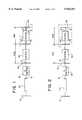
- FIG. 1illustrates the disclosed laser generation system having an intra-cavity linear configuration
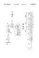
- FIG. 2illustrates the disclosed laser generation system having an inter-cavity linear configuration
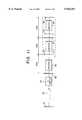
- FIG. 3is a legend indicating harmonics as shown in the drawings.
- FIG. 4is a graph illustrating the THG power over a range of pulse repetition rates
- FIGS. 5-11illustrate alternative embodiments for generating higher order harmonics
- FIG. 12illustrates the UV output power of the laser of FIG. 1 for attaining output power greater than about 11 W;
- FIG. 13illustrates the UV output power measured as a function of the Q-switch repetition rate
- FIG. 14illustrates the spatial profile of the TEM00 mode output.
- FIG. 1illustrates an intra-cavity configuration
- FIG. 2illustrates an inter-cavity configuration, as described herein.
- the disclosed laser generation system and methodoperates as a continuous wave (CW) pumped laser, or alternatively a pulsed pumped laser, having a linear configuration.
- the laserincludes a cavity having a first mirror 10, a lasing rod 20, an acousto-optic Q-switch 22, a second mirror 50, a SHG crystal 30, a third mirror 52, a THG crystal 32, and a fourth mirror 54.
- Other elements known in the art, such as the CW emitter and the structural frame for holding the components,are included in the laser but are not shown in FIG. 1 for clarity of illustration.
- the CW emittermay be a CW Kr arc-lamp or at least one laser diode for electromagnetically pumping the lasing rod 20.
- the laser rod 20may be a 145 mm Nd:YAG rod as a laser active medium.
- the lasing rod 20may be composed of Nd:YLF, Nd:YVO 4 , Yb:YAG, or other laser active media known in the art.
- the SHG crystal 30may be a LBO crystal for type-I SHG.
- the SHG crystal 30may be composed of known SHG crystals such as potassium titanyl phosphate (KTP), barium metaborate (BBO), LiIO 3 , LiNbO 3 , or other SHG devices or elements known in the art for either type-I phase-matching or type-II phase-matching.
- the SHG crystal 30has anti-reflection (AR) characteristics at 1064 nm and at 532 nm.
- the THG crystal 32may be a LBO crystal for type-II THG.
- the THG crystal 32may be composed of known THG crystals such as KTP, KDP, ADP, BBO, CLBO, LiIO 3 , LiNbO 3 , or other THG devices or elements known in the art for either type-I phase-matching or type-II phase-matching.
- the THG crystal 32has AR characteristics at 1064 nm, at 532 nm, and at 355 nm.
- the first mirror 10is coated for high reflection (HR), such as over 90% reflection, at 1064 nm; the second mirror 50 is coated for AR at 1064 nm and HR at 532 nm; the third mirror 52 is coated for AR at 1064 nm, AR at 532 nm, and HR at 355 nm; and the fourth mirror 54 is coated for HR at 1064 nm, HR at 532 nm, and high transmission (HT) (or, alternatively, AR), such as over about 90% transmission, at 355 nm.
- HRhigh reflection
- HThigh transmission
- the mirrors 10 and 50-54 and/or the coating thereof with such high degrees of reflection and transmissionare commercially available from the Shanghai Institute of Optics and Fine Mechanics, Academia Sinica, Shanghai, China.
- the main cavity of the disclosed laser generation system having the intra-cavity configurationis formed by the mirrors 10 and 54, which cause oscillation of the fundamental 12 at 1064 nm using the Nd:YAG rod 20.
- the harmonicsare illustrated in FIG. 1 in conjunction with the legend shown in FIG. 3, in which the fundamental 12 is shown as a first dashed line, the second harmonic 14 is shown as a second dashed line, and higher order harmonics with N ⁇ 3 are shown as solid lines, such as the solid line 16 in FIG. 1, in which N is the order of the harmonic.
- the mirrors 50 and 54form a first sub-cavity for the intra-cavity SHG to create the second harmonic 14 therein, and the mirrors 52 and 54 form a second sub-cavity for the double-pass and/or multi--pass intra-cavity THG 32, such that the fundamental 12 and the second harmonic 14 generate at least a third harmonic, shown as the solid line 16.
- the use of a double-pass and/or multi-pass intra-cavity THG 32provides greater efficiency.
- the use of the third mirror 52which is a dichroic mirror for harmonic separation and being HR at 355 nm, also prevents UV radiation, for example, UV at 355 nm, generated by the THG crystal 32 from reflecting back toward the main cavity, including the rod 20, as well as toward the SHG crystal 30, thus preventing damage to the optical components due to the high intensity UV.
- the disclosed laser generation systemprovides high UV output depending upon the pulse repetition rate, since the THG crystal 32 performs THG as a function of the pulse repetition rate.
- the output of the THG crystal 32is about 8 W at about 5 kHz and is about 3 W at about 20 kHz.
- a maximum power achievable by the disclosed laser generation systemis about 8.8 W at a pulse repetition rate of about 6 kHz.
- Such high UV output power at such pulse repetition ratesis advantageous for many diverse applications, such as medical procedures, scientific experiments, and industrial applications.
- the non-linear conversion efficiency between the SHG crystal 30 and the THG crystal 32 in the disclosed laser generation systemmay be estimated at a moderate repetition rate of about 10 kHz. At such a repetition rate, the disclosed laser generation system generates about 20 W for SHG and about 6.8 W for THG from the Nd:YAG oscillator 20. Such power values correspond to an effective SHG-to-THG conversion efficiency of about 34%, which is a relatively high efficiency for laser applications.
- the rod 20 in FIG. 1may be a lamp-pumped Nd:YLF crystal, with subsequent sub-cavities for SHG and THG, as well as higher order harmonics, as described herein.
- Nd:YLF crystalthe disclosed laser generation system attains about 11.5 W of UV power at about 351 nm when pulsed at a repetition rate of about 2 kHz. Accordingly, such SHG and THG provides relatively high UV power for a variety of lamp-pumped crystals.
- the cavity designis relatively simple and compact, allowing the overall length of the laser head to be about 74 cm.
- the disclosed laser generation system in FIG. 1may be adapted for performing fourth harmonic generation (4HG), in which the crystal 32 and mirrors 52-54 are adapted for 4HG.
- the third mirror 52is coated to be HR at 1064 nm, AR at 532 nm, and HR at 266 nm
- the fourth mirror 54is coated to be HR at 532 nm and AR at 266 nm.
- the 4HG crystal 32is an LBO crystal which is AR at 532 nm and AR at 266 nm. It is understood that other types of crystals may be used, as described herein and as known in the art.
- the sub-cavity formed between the mirrors 52, 54performs as a double-pass intra-cavity 4HG for generating a fourth harmonic from the second harmonic 14.
- the second harmonicis depicted as a dashed line, while the fourth harmonic is a higher order harmonic depicted as the solid line 16.
- the disclosed laser generation systemhas an inter-cavity configuration; that is, the sub-cavity generating the higher harmonics is external to the main cavity, but the sub-cavity is electromagnetically coupled to the main cavity.
- the disclosed laser generation system in the inter-cavity configurationhas a first mirror 10, a rod 20, a Q-switch 22, a second mirror 50, and a SHG crystal 30, as described above for FIG. 1.
- a third mirror 56is included such that the main cavity of FIG. 2 is formed between the mirrors 10 and 56.
- harmonics of higher orders than twomay be generated.
- a 4HG crystal 34is disposed between a fourth mirror 57 and a fifth mirror 58 to form a sub-cavity external to the main cavity.
- the third mirror 56is coated to be HR at 1064 nm, AR at 532 nm, and AR at 355 nm;
- the fourth mirror 57is coated to be AR at 532 nm and HR at 355 nm;
- the fifth mirror 58is coated to be HR at 532 nm and AR at 266 nm.
- the 4HG crystal 34is an LBO which is AR at 532 nm and AR at 266 nm. It is understood that other types of crystals may be used, as described herein and as known in the art.
- the main cavityincluding the mirrors 10 and 56, generates oscillations of the fundamental at 1064 nm using, for example, an Nd:YAG rod 20, but the third mirror 56 limits the fundamental to oscillate within the main cavity and the sub-cavity having the SHG crystal 30.
- Another sub-cavityis formed between the mirrors 50, 58 for inter-cavity SHG, while the sub-cavity formed between the mirrors 56, 58 performs as a double-pass inter-cavity 4HG for generating a fourth harmonic 18 from the second harmonic 14.
- the second harmonic 14is depicted as a dashed line
- the fourth harmonic 18is a higher order harmonic depicted as a solid line.
- the disclosed laser generation systemuses the inter-cavity configuration of FIG. 2, the disclosed laser generation system generates the fourth harmonic 18 outside of the main cavity, which reduces any loss of power due to individual losses from each component.
- the coating of the third mirror 56prevents transmission of high intensity UV back toward the rod 20 and other components to avoid damage thereto.
- FIGS. 5-11it is possible to have other alternative embodiments utilizing coated mirrors as described above for generating higher order harmonics, according to the present invention.
- appropriately coated mirrors and crystalsare adapted to form sub-cavities for 2HG, 4HG, and 5HG for intra-cavity harmonics generation.
- the mirror 50is coated to be AR for 1064 nm and HR for 532 nm; the mirror 52 is coated to be AR for 1064 nm, HR for 532 nm, and AR for 355 nm; the mirror 60 is coated to be AR for 1064 nm, HR for 532 nm, AR for 355 nm, and AR for 266 nm; and the mirror 62 is coated to be HR for 1064 nm, HR for 532 nm, and AR for 213 nm.
- the 2HG crystal 30may be composed of LBO and is AR for 1064 nm and AR for 532 nm;
- the 4HG crystal 32may be composed of LBO and is AR for 1064 nm, AR for 532 nm, and AR for 355 nm; and the 4HG crystal 32 may be composed of LBO and is AR for 1064 nm, HR for 266 nm, and AR for 213 nm.
- mirrors 50 and 60form a sub-cavity for intra-cavity 2HG
- mirrors 52 and 62form a sub-cavity for intra-cavity 4HG
- mirrors 60-62form a sub-cavity for double-pass intra-cavity 5HG.
- the mirror 50is coated for AR at 1064 nm and HR for 532 nm; the mirror 64 is coated for HR at 1064 nm, HR at 532 nm, and AR at 355 nm; and the mirror 66 is coated for HR at 1064 nm, HR at 532 nm, and HR at 355 nm.
- the crystal 30is AR at 1064 nm and AR at 532 nm; and the crystal 32 is AR at 1064 nm, HR at 532 nm, and HR at 355 nm.
- the mirrors 50 and 66form a sub-cavity for intra-cavity 2HG
- the mirrors 64-64form a sub-cavity for double-pass intra-cavity 3HG.
- the sub-cavity between the mirrors 64-66has a longitudinal axis which is at an angle of about 90° to a longitudinal axis of the main cavity.
- the mirror 68is coated for AR at 1064 nm and HR for 532 nm; the mirror 64 is coated for HR at 1064 nm, HR at 532 nm, and AR at 355 nm; and the mirror 66 is coated for HR at 1064 nm, HR at 532 nm, and HR at 355 nm.
- the crystal 30is AR at 1064 nm and AR at 532 nm; and the crystal 32 is AR at 1064 nm, HR at 532 nm, and HR at 355 nm.
- the mirrors 66-68form a sub-cavity for intra-cavity 2HG
- the mirrors 64-66form a sub-cavity for double-pass intra-cavity 3HG.
- the path from the mirror 68 to mirror 64is at an angle of about 90° to a longitudinal axis of the main cavity.
- the sub-cavity of the mirrors 64-66has a longitudinal axis which is at an angle of about 90° to the longitudinal axis of the path from the mirror 68 to mirror 64, so that the laser beams are directed in the sub-cavity between mirrors 64-66 to be parallel to beams in the main cavity.
- appropriately coated mirrors and crystalsare adapted to form sub-cavities for 2HG, 4HG and 6HG for intra-cavity harmonics generation, using mirrors 50, 56, 58, and 68 for forming sub-cavities which include crystals 30, 34, and 38, respectively, for 2HG, 4HG, and 6HG, respectively.
- the coating of the mirrors and the characteristics of the mirrors and the crystals to be AR and HR for specific frequenciesmay be as described above for FIGS. 1-2 and 5-7.
- One having ordinary skill in the artmay adapt such AR and HR characteristics to generate 2HG, 4HG, and 6HG, respectively.
- appropriately coated mirrors crystalsare adapted to form sub-cavities for 2HG, 4HG, 5HG, and 6HG for intra-cavity harmonics generation, using mirrors 50, 52, 60, 62, and 70 for forming sub-cavities which include crystals 30, 32, 36, and 40, respectively, for 2HG, 4HG, 5HG, and 6HG, respectively.
- the coating of the mirrors and the characteristics of the mirrors and the crystals to be AR and HR for specific frequenciesmay be as described above for FIGS. 1-2 and 5-7.
- One having ordinary skill in the artmay adapt such AR and HR characteristics to generate 2HG, 4HG, and 6HG, respectively.
- appropriately coated mirrors and crystalsare adapted to form sub-cavities for 2HG, 3HG, and 5HG for intra-cavity harmonics generation.
- the mirror 50is coated to be AR for 1064 nm and HR for 532 nm;
- the mirror 52is coated to be AR for 1064 nm, AR for 532 nm, and HR for 355 nm;
- the mirror 56is coated to be HR for 1064 nm, AR for 532 nm, and AR for 355 nm;
- the mirror 72is coated to be AR for 532 nm, AR for 355 nm, and HR for 213 nm;
- the mirror 74is coated to be HR for 532 nm, HR for 355 nm, and AR for 213 nm.
- the 2HG crystal 30may be composed of LBO and is AR for 1064 nm and AR for 532 nm;
- the 3HG crystal 32may be composed of LBO and is AR for 1064 nm, AR for 532 nm, and AR for 355 nm;
- the 5HG crystal 42may be composed of LBO and is AR for 532 nm, AR for 355 nm, and AR for 213 nm.
- the mirrors 10 and 56form the main cavity for oscillating the fundamental at 1064 nm using a Nd:YAG rod for rod 20.
- the mirrors 50 and 74form a sub-cavity for intra-cavity 2HG
- mirrors 52 and 74form a sub-cavity for double-pass intra-cavity 3HG
- mirrors 72-74form a sub-cavity for double-pass intra-cavity 5HG.
- appropriately coated mirrors and crystalsare adapted to form sub-cavities for 2HG, 3HG, and 6HG for intra-cavity harmonics generation.
- the mirror 50is coated to be AR for 1064 nm and HR for 532 nm;
- the mirror 52is coated to be AR for 1064 nm, AR for 532 nm, and HR for 355 nm;
- the mirror 56is coated to be HR for 1064 nm, HR for 532 nm, and AR for 355 nm;
- the mirror 72is coated to be AR for 355 nm and for 177 nm;
- the mirror 76is coated to be HR for 355 nm and AR for 177 nm.
- the 2HG crystal 30may be composed of LBO and is AR for 1064 nm and AR for 532 nm;
- the 3HG crystal 32may be composed of LBO and is AR for 1064 nm, AR for 532 nm, and AR for 355 nm;
- the 6HG crystal 44may be composed of LBO and is AR for 355 nm and AR for 177 nm.
- the mirrors 10 and 56form the main cavity for oscillating the fundamental at 1064 nm using a Nd:YAG rod for rod 20.
- the mirrors 50 and 74form a sub-cavity for intra-cavity 2HG
- mirrors 52 and 76form a sub-cavity for double-pass intra-cavity 3HG
- mirrors 72 and 76form a sub-cavity for double-pass intra-cavity 6HG.
- FIGS. 5-11may be adapted to be inter-cavity configurations for improved performance, as described above.
- Improved performancemay be gained, for example, using an implementation of the apparatus in FIG. 1 to attain a very high UV output of over about 11 W of Transverse Electromagnetic mode (TEM00 mode) and about 23 W of multi-mode average output power, at wavelengths of about 351 nm using a Q-switched Nd:YLF laser with the intra-cavity UV generation described above.
- TEM00 modeTransverse Electromagnetic mode
- multi-mode average output powerat wavelengths of about 351 nm using a Q-switched Nd:YLF laser with the intra-cavity UV generation described above.
- the laseris a linear laser resonator having a cavity length of about 95 cm.
- the laseruses a lasing rod 20 composed of Nd:YLF which is about 4 mm. in diameter and about 145 mm. long.
- the Q-switch 22is an acousto-optic Q-switch.
- the crystal 30is an LBO crystal for second harmonic generation, and the crystal 32 is an LBO crystal for third harmonic generation.
- a spatial mode selector(not shown in FIG. 1) may be used to select either TEM00 mode or multi-mode output by varying the size of an aperture of the spatial mode selector.
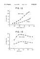
- FIG. 12illustrates the UV output power of the laser at a Q-switch repetition rate of 2.5, with the UV output power being measured against the pump current. Without spatial mode variation, the UV output tracks linearly with the lamp current. No significant saturation is observed up to a lamp current of about 35 A, when the UV output at 351 nm. is about 11.5 W for the TEM00 mode, and is about 23.2 W for the multi-mode.
- FIG. 13illustrates the UV output power measured as a function of the Q-switch repetition rate at a lamp current of about 32 A.
- the output powerincreases with a repetition rate up to about 2 kHz, and the output power remains substantially constant in the pulse repetition frequency (PRF) range of about 2 kHz to about 5 kHz for both TEM00 mode and multi-mode operation.
- PRFpulse repetition frequency
- Such an increase of power at relatively low repetition ratesmay be attributed to the energy storage time of the Nd:YLF rod 20.
- the repetition rateincreases to higher than 2 kHz, the high non-linear conversion efficiency leads to the saturation behavior of the UV output.
- a relatively small decrease in powermay be observed due to longer pulse widths, since the pump energy; that is, the lamp current, is held substantially constant.
- FIG. 14illustrates the spatial profile of the TEM00 mode output at about 11.5 W with Gaussian fits for both the x-y dimensions, with a substantial match between the measured data and the Gaussian fits.
- the intensity of the TEM00 mode outputis measured in arbitrary units against a pixel number parameter.
- the spatial mode profiles in both the horizontal and vertical directions for the TEM00 modeare plotted using open squares, and the spatial mode profiles in both the horizontal and vertical directions for the Gaussian fits are plotted using solid dots. As shown in FIG. 14, good agreement is obtained between the TEM00 mode data and the Gaussian fit data.
- the measured M 2 valueis about 1.6, and the pulse-to-pulse amplitude stability is measured to be less than about 2%, with a pulse width of about 80 ns. at about 35 A.
Landscapes
- Physics & Mathematics (AREA)
- Electromagnetism (AREA)
- Nonlinear Science (AREA)
- Engineering & Computer Science (AREA)
- Plasma & Fusion (AREA)
- Optics & Photonics (AREA)
- Lasers (AREA)
- Optical Modulation, Optical Deflection, Nonlinear Optics, Optical Demodulation, Optical Logic Elements (AREA)
Abstract
Description
Claims (23)
Priority Applications (6)
| Application Number | Priority Date | Filing Date | Title |
|---|---|---|---|
| US09/017,342US5943351A (en) | 1997-05-16 | 1998-02-02 | Intra-cavity and inter-cavity harmonics generation in high-power lasers |
| CA002289670ACA2289670C (en) | 1997-05-16 | 1998-05-14 | Intra-cavity and inter-cavity harmonics generation in high power lasers |
| AU75765/98AAU7576598A (en) | 1997-05-16 | 1998-05-14 | Intra-cavity and inter-cavity harmonics generation in high power lasers |
| PCT/US1998/010100WO1998052260A1 (en) | 1997-05-16 | 1998-05-14 | Intra-cavity and inter-cavity harmonics generation in high power lasers |
| JP54964798AJP2001525946A (en) | 1997-05-16 | 1998-05-14 | Intracavity and intercavity harmonic generation in high power lasers |
| EP98923476AEP1010221A4 (en) | 1997-05-16 | 1998-05-14 | Intra-cavity and inter-cavity harmonics generation in high power lasers |
Applications Claiming Priority (2)
| Application Number | Priority Date | Filing Date | Title |
|---|---|---|---|
| US4675197P | 1997-05-16 | 1997-05-16 | |
| US09/017,342US5943351A (en) | 1997-05-16 | 1998-02-02 | Intra-cavity and inter-cavity harmonics generation in high-power lasers |
Publications (1)
| Publication Number | Publication Date |
|---|---|
| US5943351Atrue US5943351A (en) | 1999-08-24 |
Family
ID=26689748
Family Applications (1)
| Application Number | Title | Priority Date | Filing Date |
|---|---|---|---|
| US09/017,342Expired - LifetimeUS5943351A (en) | 1997-05-16 | 1998-02-02 | Intra-cavity and inter-cavity harmonics generation in high-power lasers |
Country Status (6)
| Country | Link |
|---|---|
| US (1) | US5943351A (en) |
| EP (1) | EP1010221A4 (en) |
| JP (1) | JP2001525946A (en) |
| AU (1) | AU7576598A (en) |
| CA (1) | CA2289670C (en) |
| WO (1) | WO1998052260A1 (en) |
Cited By (38)
| Publication number | Priority date | Publication date | Assignee | Title |
|---|---|---|---|---|
| WO2001047072A3 (en)* | 1999-11-02 | 2001-12-13 | Applied Harmonics Corp | High-power frequency conversion apparatus using a multi-pass conjugate-image sub-cavity design |
| US6341009B1 (en) | 2000-02-24 | 2002-01-22 | Quantronix Corporation | Laser delivery system and method for photolithographic mask repair |
| WO2002073322A1 (en)* | 2001-03-12 | 2002-09-19 | Electro Scientific Industries, Inc. | Quasi-cw diode-pumped, solid-state uv laser system and method employing same |
| US20030047541A1 (en)* | 2001-03-12 | 2003-03-13 | Yunlong Sun | Quasi-CW diode-pumped, solid-state harmonic laser system and method employing same |
| US6633594B1 (en)* | 1999-08-18 | 2003-10-14 | Japan Atomic Energy Research Institute | Method for changing a wavelength of a laser light |
| US6690692B2 (en) | 2002-01-29 | 2004-02-10 | Hans Laser Technology Co., Ltd. | Third harmonic laser system |
| US20040095980A1 (en)* | 2002-11-19 | 2004-05-20 | Masayuki Momiuchi | Solid-state laser device |
| US20040146076A1 (en)* | 2003-01-24 | 2004-07-29 | Dudley David R. | Diode pumped laser with intracavity harmonics |
| US6806440B2 (en) | 2001-03-12 | 2004-10-19 | Electro Scientific Industries, Inc. | Quasi-CW diode pumped, solid-state UV laser system and method employing same |
| US20050100071A1 (en)* | 2000-08-31 | 2005-05-12 | Taylor Alan G. | Electromagnetic radiation generation using a laser produced plasma |
| US20050254530A1 (en)* | 2004-05-14 | 2005-11-17 | Yunlong Sun | Multi-output harmonic laser and methods employing same |
| US20050279453A1 (en)* | 2004-06-17 | 2005-12-22 | Uvtech Systems, Inc. | System and methods for surface cleaning |
| US20060018350A1 (en)* | 2004-07-20 | 2006-01-26 | Lightwave Electronics Corporation | Laser burst boosting method and apparatus |
| US6999483B1 (en)* | 2000-12-19 | 2006-02-14 | Photonics Industries Int'l. | External 3rd, 4th and 5th harmonic laser |
| US20060268949A1 (en)* | 2005-05-24 | 2006-11-30 | Christoph Gohle | Method and radiation source for generating pulsed coherent radiation |
| US20070000877A1 (en)* | 2003-03-26 | 2007-01-04 | Ulrich Durr | Laser device which is used to pierce holes in components of a fluid-injection device |
| US20070041421A1 (en)* | 2005-08-18 | 2007-02-22 | Texas Instruments Incorporated | Holographic element for stabilizing coupled laser and SHG resonators |
| US20070047600A1 (en)* | 2005-08-15 | 2007-03-01 | Pavilion Integration Corportation | Low-Noise Monolithic Microchip Lasers Capable of Producing Wavelengths Ranging From IR to UV Based on Efficient and Cost-Effective Frequency Conversion |
| US20070286248A1 (en)* | 2006-06-12 | 2007-12-13 | Samsung Electronics Co., Ltd. | Nonlinear optical modulator |
| US20080008215A1 (en)* | 2006-07-10 | 2008-01-10 | Choong Bum Park | Laser apparatus and method for harmonic beam generation |
| WO2008017214A1 (en)* | 2006-08-04 | 2008-02-14 | Shenzhen Han's Laser Technology Co., Limited | A method for generating a fourth harmonic solid laser |
| US20080037597A1 (en)* | 2004-02-23 | 2008-02-14 | Michael Mason | Laser Apparatus |
| US20080259436A1 (en)* | 2007-01-15 | 2008-10-23 | Seiko Epson Corporation | Laser light source device, illumination device, image display device, and monitor |
| US20080296272A1 (en)* | 2007-05-31 | 2008-12-04 | Electro Scientific Industries, Inc. | Multiple laser wavelength and pulse width process drilling |
| EP1717916A3 (en)* | 2005-03-31 | 2009-07-15 | Kabushiki Kaisha Topcon | Laser oscillation device |
| US20100246615A1 (en)* | 2009-03-27 | 2010-09-30 | Electro Scientific Industries, Inc. | Intracavity harmonic generation using a recycled intermediate harmonic |
| US20100272135A1 (en)* | 2009-04-28 | 2010-10-28 | Dmitri Vladislavovich Kuksenkov | Self-Seeded Wavelength Conversion |
| US20100309438A1 (en)* | 2007-11-27 | 2010-12-09 | Tetsuro Mizushima | Wavelength conversion laser |
| WO2011029294A1 (en)* | 2009-09-11 | 2011-03-17 | 青岛海信电器股份有限公司 | Laser display light source and laser display system |
| CN102299471A (en)* | 2011-06-27 | 2011-12-28 | 中国电子科技集团公司第三十四研究所 | Extracavity resonant ultraviolet laser generating device |
| CN101604814B (en)* | 2009-06-24 | 2012-10-03 | 深圳市大族激光科技股份有限公司 | Ultraviolet frequency doubling laser and point moving method thereof |
| CN103001112A (en)* | 2012-07-06 | 2013-03-27 | 中国科学院福建物质结构研究所 | All-solid-state quadruple-harmonic ultraviolet laser |
| CN103094829A (en)* | 2012-11-30 | 2013-05-08 | 中国科学院福建物质结构研究所 | Quadruplicated frequency ultraviolet laser outside cavity |
| WO2014029996A1 (en)* | 2012-08-21 | 2014-02-27 | Powerlase Photonics Limited | High power solid-state laser with replaceable module for uv generation |
| US8817831B1 (en) | 2013-01-30 | 2014-08-26 | Photonics Industries Int'l. | High power UV lasers |
| EP2850706A4 (en)* | 2012-05-07 | 2016-05-18 | Continuum | Intra-cavity harmonic generation in lasers |
| US9991670B2 (en) | 2014-02-24 | 2018-06-05 | Lasertec Corporation | Laser light source device and inspection device |
| CN112688144A (en)* | 2020-12-28 | 2021-04-20 | 上海飞博激光科技有限公司 | Laser based on cavity-outside bi-pass frequency doubling structure |
Families Citing this family (4)
| Publication number | Priority date | Publication date | Assignee | Title |
|---|---|---|---|---|
| JP2001340498A (en)* | 2000-06-06 | 2001-12-11 | Bridgestone Sports Co Ltd | Golf ball marking method |
| DE10118793B4 (en)* | 2000-12-01 | 2013-11-14 | Crylas Crystal Laser Systems Gmbh | UV solid state laser |
| TWI269924B (en) | 2001-05-25 | 2007-01-01 | Mitsubishi Materials Corp | Optical wavelength conversion method, optical wavelength conversion system, program and medium, and laser oscillation system |
| JP5170439B2 (en)* | 2008-12-02 | 2013-03-27 | オムロン株式会社 | Solid state laser oscillator |
Citations (5)
| Publication number | Priority date | Publication date | Assignee | Title |
|---|---|---|---|---|
| US4618957A (en)* | 1985-04-17 | 1986-10-21 | Quantronix Corporation | Frequency doubling a laser beam by using intracavity type II phase matching |
| US5025446A (en)* | 1988-04-01 | 1991-06-18 | Laserscope | Intra-cavity beam relay for optical harmonic generation |
| US5027361A (en)* | 1988-06-21 | 1991-06-25 | Board Of Trustees Of Leland Stanford, Jr., University | Efficient laser harmonic generation employing a low-loss external optical resonator |
| US5144630A (en)* | 1991-07-29 | 1992-09-01 | Jtt International, Inc. | Multiwavelength solid state laser using frequency conversion techniques |
| US5278852A (en)* | 1990-10-11 | 1994-01-11 | Kigre, Inc. | Intra-cavity high order harmonic laser |
Family Cites Families (2)
| Publication number | Priority date | Publication date | Assignee | Title |
|---|---|---|---|---|
| JPH01274487A (en)* | 1988-04-27 | 1989-11-02 | Hamamatsu Photonics Kk | Optical wavelength converter |
| JPH03145777A (en)* | 1989-10-31 | 1991-06-20 | Hoya Corp | Harmonic generating laser device |
- 1998
- 1998-02-02USUS09/017,342patent/US5943351A/ennot_activeExpired - Lifetime
- 1998-05-14AUAU75765/98Apatent/AU7576598A/ennot_activeAbandoned
- 1998-05-14CACA002289670Apatent/CA2289670C/ennot_activeExpired - Lifetime
- 1998-05-14JPJP54964798Apatent/JP2001525946A/enactivePending
- 1998-05-14EPEP98923476Apatent/EP1010221A4/ennot_activeWithdrawn
- 1998-05-14WOPCT/US1998/010100patent/WO1998052260A1/enactiveApplication Filing
Patent Citations (5)
| Publication number | Priority date | Publication date | Assignee | Title |
|---|---|---|---|---|
| US4618957A (en)* | 1985-04-17 | 1986-10-21 | Quantronix Corporation | Frequency doubling a laser beam by using intracavity type II phase matching |
| US5025446A (en)* | 1988-04-01 | 1991-06-18 | Laserscope | Intra-cavity beam relay for optical harmonic generation |
| US5027361A (en)* | 1988-06-21 | 1991-06-25 | Board Of Trustees Of Leland Stanford, Jr., University | Efficient laser harmonic generation employing a low-loss external optical resonator |
| US5278852A (en)* | 1990-10-11 | 1994-01-11 | Kigre, Inc. | Intra-cavity high order harmonic laser |
| US5144630A (en)* | 1991-07-29 | 1992-09-01 | Jtt International, Inc. | Multiwavelength solid state laser using frequency conversion techniques |
Non-Patent Citations (6)
| Title |
|---|
| "Third-Harmonic Generation in Nd:YLF", Lasers & Optronics (R. Cunningham, Ed.) (undated), p. 74. |
| A.J. Alfrey, "Intracavity Tripling of Diode-Pumped Nd:YV04 at High Q-Switch Repetition Rates", Conference on Lasers and Electro-Optics (CLEO) 1996, pp. CPD19-1 to CPD19-5. |
| A.J. Alfrey, Intracavity Tripling of Diode Pumped Nd:YV04 at High Q Switch Repetition Rates , Conference on Lasers and Electro Optics (CLEO) 1996, pp. CPD19 1 to CPD19 5.* |
| Pixton; Tripling YAG frequency; Laser Focus;pp. 66 70 Jul. 1978.* |
| Pixton; Tripling YAG frequency; Laser Focus;pp. 66-70 Jul. 1978. |
| Third Harmonic Generation in Nd:YLF , Lasers & Optronics (R. Cunningham, Ed.) (undated), p. 74.* |
Cited By (63)
| Publication number | Priority date | Publication date | Assignee | Title |
|---|---|---|---|---|
| US6633594B1 (en)* | 1999-08-18 | 2003-10-14 | Japan Atomic Energy Research Institute | Method for changing a wavelength of a laser light |
| WO2001047072A3 (en)* | 1999-11-02 | 2001-12-13 | Applied Harmonics Corp | High-power frequency conversion apparatus using a multi-pass conjugate-image sub-cavity design |
| US6341009B1 (en) | 2000-02-24 | 2002-01-22 | Quantronix Corporation | Laser delivery system and method for photolithographic mask repair |
| US6956885B2 (en) | 2000-08-31 | 2005-10-18 | Powerlase Limited | Electromagnetic radiation generation using a laser produced plasma |
| US20050100071A1 (en)* | 2000-08-31 | 2005-05-12 | Taylor Alan G. | Electromagnetic radiation generation using a laser produced plasma |
| US6999483B1 (en)* | 2000-12-19 | 2006-02-14 | Photonics Industries Int'l. | External 3rd, 4th and 5th harmonic laser |
| US6781090B2 (en) | 2001-03-12 | 2004-08-24 | Electro Scientific Industries, Inc. | Quasi-CW diode-pumped, solid-state harmonic laser system and method employing same |
| GB2390994A (en)* | 2001-03-12 | 2004-01-28 | Electro Scient Ind Inc | Quasi-CW Diode-pumped, solid-state UV laser system and method employing same |
| US20030047541A1 (en)* | 2001-03-12 | 2003-03-13 | Yunlong Sun | Quasi-CW diode-pumped, solid-state harmonic laser system and method employing same |
| GB2390994B (en)* | 2001-03-12 | 2004-10-13 | Electro Scient Ind Inc | Quasi-CW Diode-pumped, solid-state UV laser system and method employing same |
| US6806440B2 (en) | 2001-03-12 | 2004-10-19 | Electro Scientific Industries, Inc. | Quasi-CW diode pumped, solid-state UV laser system and method employing same |
| WO2002073322A1 (en)* | 2001-03-12 | 2002-09-19 | Electro Scientific Industries, Inc. | Quasi-cw diode-pumped, solid-state uv laser system and method employing same |
| US6690692B2 (en) | 2002-01-29 | 2004-02-10 | Hans Laser Technology Co., Ltd. | Third harmonic laser system |
| US20040095980A1 (en)* | 2002-11-19 | 2004-05-20 | Masayuki Momiuchi | Solid-state laser device |
| US6870862B2 (en)* | 2002-11-19 | 2005-03-22 | Kabushiki Kaisha Topcon | Solid-state laser device |
| US20040146076A1 (en)* | 2003-01-24 | 2004-07-29 | Dudley David R. | Diode pumped laser with intracavity harmonics |
| EP1590864A4 (en)* | 2003-01-24 | 2006-03-08 | Spectra Physics | Diode pumped laser with intracavity harmonics |
| US7016389B2 (en) | 2003-01-24 | 2006-03-21 | Spectra Physics, Inc. | Diode pumped laser with intracavity harmonics |
| US20070000877A1 (en)* | 2003-03-26 | 2007-01-04 | Ulrich Durr | Laser device which is used to pierce holes in components of a fluid-injection device |
| US7804041B2 (en)* | 2003-03-26 | 2010-09-28 | Lasag Ag | Laser device for drilling holes in components of a fluid injection device |
| US20080037597A1 (en)* | 2004-02-23 | 2008-02-14 | Michael Mason | Laser Apparatus |
| US7970039B2 (en) | 2004-02-23 | 2011-06-28 | Powerlase Ltd. | Laser apparatus |
| US7139294B2 (en) | 2004-05-14 | 2006-11-21 | Electro Scientific Industries, Inc. | Multi-output harmonic laser and methods employing same |
| US20050254530A1 (en)* | 2004-05-14 | 2005-11-17 | Yunlong Sun | Multi-output harmonic laser and methods employing same |
| CN1977429B (en)* | 2004-05-14 | 2012-02-01 | 电子科学工业公司 | Multi-output harmonic laser and methods employing same |
| US20060231204A1 (en)* | 2004-06-17 | 2006-10-19 | Uvtech Systems, Inc. | Portable system for semiconductor manufacturing |
| US7514015B2 (en) | 2004-06-17 | 2009-04-07 | Uvtech Systems | Method for surface cleaning |
| US20050279380A1 (en)* | 2004-06-17 | 2005-12-22 | Uvtech Systems, Inc. | Method for surface cleaning |
| US20050279453A1 (en)* | 2004-06-17 | 2005-12-22 | Uvtech Systems, Inc. | System and methods for surface cleaning |
| US20060018350A1 (en)* | 2004-07-20 | 2006-01-26 | Lightwave Electronics Corporation | Laser burst boosting method and apparatus |
| US7352784B2 (en) | 2004-07-20 | 2008-04-01 | Jds Uniphase Corporation | Laser burst boosting method and apparatus |
| EP1717916A3 (en)* | 2005-03-31 | 2009-07-15 | Kabushiki Kaisha Topcon | Laser oscillation device |
| US20060268949A1 (en)* | 2005-05-24 | 2006-11-30 | Christoph Gohle | Method and radiation source for generating pulsed coherent radiation |
| US7672342B2 (en)* | 2005-05-24 | 2010-03-02 | MAX-PLANCK-Gesellschaft zur Förderung der Wissenschaften e.V. | Method and radiation source for generating pulsed coherent radiation |
| US20070047600A1 (en)* | 2005-08-15 | 2007-03-01 | Pavilion Integration Corportation | Low-Noise Monolithic Microchip Lasers Capable of Producing Wavelengths Ranging From IR to UV Based on Efficient and Cost-Effective Frequency Conversion |
| US7535938B2 (en) | 2005-08-15 | 2009-05-19 | Pavilion Integration Corporation | Low-noise monolithic microchip lasers capable of producing wavelengths ranging from IR to UV based on efficient and cost-effective frequency conversion |
| US20070041421A1 (en)* | 2005-08-18 | 2007-02-22 | Texas Instruments Incorporated | Holographic element for stabilizing coupled laser and SHG resonators |
| US20070286248A1 (en)* | 2006-06-12 | 2007-12-13 | Samsung Electronics Co., Ltd. | Nonlinear optical modulator |
| US20080008215A1 (en)* | 2006-07-10 | 2008-01-10 | Choong Bum Park | Laser apparatus and method for harmonic beam generation |
| US7627008B2 (en) | 2006-07-10 | 2009-12-01 | Choong Bum Park | Laser apparatus and method for harmonic beam generation |
| WO2008017214A1 (en)* | 2006-08-04 | 2008-02-14 | Shenzhen Han's Laser Technology Co., Limited | A method for generating a fourth harmonic solid laser |
| US20080259436A1 (en)* | 2007-01-15 | 2008-10-23 | Seiko Epson Corporation | Laser light source device, illumination device, image display device, and monitor |
| US7679817B2 (en)* | 2007-01-15 | 2010-03-16 | Seiko Epson Corporation | Laser light source device, illumination device, image display device, and monitor |
| CN101687278A (en)* | 2007-05-31 | 2010-03-31 | 伊雷克托科学工业股份有限公司 | Multiple laser wavelength and pulse width process drilling |
| US20080296272A1 (en)* | 2007-05-31 | 2008-12-04 | Electro Scientific Industries, Inc. | Multiple laser wavelength and pulse width process drilling |
| US8116341B2 (en)* | 2007-05-31 | 2012-02-14 | Electro Scientific Industries, Inc. | Multiple laser wavelength and pulse width process drilling |
| US20100309438A1 (en)* | 2007-11-27 | 2010-12-09 | Tetsuro Mizushima | Wavelength conversion laser |
| US8287131B2 (en)* | 2007-11-27 | 2012-10-16 | Panasonic Corporation | Wavelength conversion laser |
| US7903701B2 (en) | 2009-03-27 | 2011-03-08 | Electro Scientific Industries, Inc. | Intracavity harmonic generation using a recycled intermediate harmonic |
| US20100246615A1 (en)* | 2009-03-27 | 2010-09-30 | Electro Scientific Industries, Inc. | Intracavity harmonic generation using a recycled intermediate harmonic |
| US20100272135A1 (en)* | 2009-04-28 | 2010-10-28 | Dmitri Vladislavovich Kuksenkov | Self-Seeded Wavelength Conversion |
| CN101604814B (en)* | 2009-06-24 | 2012-10-03 | 深圳市大族激光科技股份有限公司 | Ultraviolet frequency doubling laser and point moving method thereof |
| WO2011029294A1 (en)* | 2009-09-11 | 2011-03-17 | 青岛海信电器股份有限公司 | Laser display light source and laser display system |
| CN102299471A (en)* | 2011-06-27 | 2011-12-28 | 中国电子科技集团公司第三十四研究所 | Extracavity resonant ultraviolet laser generating device |
| CN102299471B (en)* | 2011-06-27 | 2013-03-20 | 中国电子科技集团公司第三十四研究所 | Extracavity resonant ultraviolet laser generating device |
| EP2850706A4 (en)* | 2012-05-07 | 2016-05-18 | Continuum | Intra-cavity harmonic generation in lasers |
| CN103001112A (en)* | 2012-07-06 | 2013-03-27 | 中国科学院福建物质结构研究所 | All-solid-state quadruple-harmonic ultraviolet laser |
| WO2014029996A1 (en)* | 2012-08-21 | 2014-02-27 | Powerlase Photonics Limited | High power solid-state laser with replaceable module for uv generation |
| CN104937789A (en)* | 2012-08-21 | 2015-09-23 | 高功率激光光电有限公司 | High power solid-state laser with replaceable module for uv generation |
| CN103094829A (en)* | 2012-11-30 | 2013-05-08 | 中国科学院福建物质结构研究所 | Quadruplicated frequency ultraviolet laser outside cavity |
| US8817831B1 (en) | 2013-01-30 | 2014-08-26 | Photonics Industries Int'l. | High power UV lasers |
| US9991670B2 (en) | 2014-02-24 | 2018-06-05 | Lasertec Corporation | Laser light source device and inspection device |
| CN112688144A (en)* | 2020-12-28 | 2021-04-20 | 上海飞博激光科技有限公司 | Laser based on cavity-outside bi-pass frequency doubling structure |
Also Published As
| Publication number | Publication date |
|---|---|
| AU7576598A (en) | 1998-12-08 |
| EP1010221A4 (en) | 2005-11-30 |
| CA2289670A1 (en) | 1998-11-19 |
| CA2289670C (en) | 2005-06-21 |
| EP1010221A1 (en) | 2000-06-21 |
| WO1998052260A1 (en) | 1998-11-19 |
| JP2001525946A (en) | 2001-12-11 |
Similar Documents
| Publication | Publication Date | Title |
|---|---|---|
| US5943351A (en) | Intra-cavity and inter-cavity harmonics generation in high-power lasers | |
| US5341236A (en) | Nonlinear optical wavelength converters with feedback | |
| US6229829B1 (en) | Fourth harmonic generation apparatus | |
| JP6453844B2 (en) | High-efficiency single-pass harmonic generator for circular output beams | |
| US7088744B2 (en) | Laser for use in non-linear optics | |
| Clarkson et al. | Acousto-optically induced unidirectional single mode operation of a Q-switched miniature Nd: YAG ring laser | |
| US5898717A (en) | Third harmonic generation apparatus | |
| JP4490015B2 (en) | Short pulse laser equipment | |
| Krausz et al. | Mode locking of a continuous wave Nd: glass laser pumped by a multistripe diode laser | |
| Chen et al. | High-power diode-pumped nonlinear mirror mode-locked Nd: YVO4 laser with periodically-poled KTP | |
| GB2250132A (en) | A titanium doped solid state laser | |
| Marshall et al. | Multimode pumping of optical parametric oscillators | |
| WO2007064298A1 (en) | Q-switched laser arrangement | |
| EP0572201B1 (en) | A high average power laser which generates radiation at a wavelength near 530 NM | |
| JPH0786668A (en) | Semiconductor laser pumped solid state laser device | |
| Ortiz et al. | High-average-power second harmonic generation with KTiOPO4 | |
| Hemmati et al. | High repetition-rate Q-switched and intracavity doubled diode-pumped Nd: YAG laser | |
| CN1263205C (en) | Multi-wavelength crystal laser | |
| CN110829172B (en) | Laser output method with repetition frequency 2 times electro-optic Q-switched frequency and laser | |
| Xu et al. | Comparison of intra-cavity THG between the single-and multi-pass operations | |
| McDonagh et al. | 888-nm pumping of Nd: YVO4 for high-power high-efficiency TEM00 lasers | |
| McConnell et al. | Additive-pulse mode locking of a diode-pumped Nd3+: YVO4 laser | |
| CN111404010A (en) | Quartic harmonic laser | |
| JPH01276782A (en) | Laser diode pumped solid-state laser device and optical printer | |
| CN107069394A (en) | A kind of four-time harmonic laser generator |
Legal Events
| Date | Code | Title | Description |
|---|---|---|---|
| AS | Assignment | Owner name:EXCEL/QUANTRONIX, INC., NEW YORK Free format text:ASSIGNMENT OF ASSIGNORS INTEREST;ASSIGNORS:ZHOU, FUZHENG;FU, QIANG;MAIKOWSKI, MICHAEL;REEL/FRAME:008973/0477 Effective date:19980113 | |
| AS | Assignment | Owner name:BANK OF NEW YORK, THE, NEW YORK Free format text:SECURITY INTEREST;ASSIGNOR:QUANTRONIX CORPORATION;REEL/FRAME:009423/0095 Effective date:19980814 | |
| STCF | Information on status: patent grant | Free format text:PATENTED CASE | |
| FPAY | Fee payment | Year of fee payment:4 | |
| FEPP | Fee payment procedure | Free format text:PAT HOLDER NO LONGER CLAIMS SMALL ENTITY STATUS, ENTITY STATUS SET TO UNDISCOUNTED (ORIGINAL EVENT CODE: STOL); ENTITY STATUS OF PATENT OWNER: LARGE ENTITY | |
| REFU | Refund | Free format text:REFUND - PAYMENT OF MAINTENANCE FEE, 8TH YR, SMALL ENTITY (ORIGINAL EVENT CODE: R2552); ENTITY STATUS OF PATENT OWNER: LARGE ENTITY | |
| FPAY | Fee payment | Year of fee payment:8 | |
| SULP | Surcharge for late payment | Year of fee payment:7 | |
| FEPP | Fee payment procedure | Free format text:PAYOR NUMBER ASSIGNED (ORIGINAL EVENT CODE: ASPN); ENTITY STATUS OF PATENT OWNER: LARGE ENTITY | |
| AS | Assignment | Owner name:EXCEL TECHNOLOGY, INC.,NEW YORK Free format text:RELEASE BY SECURED PARTY;ASSIGNOR:THE BANK OF NEW YORK MELLON (SUCCESSOR TO THE BANK OF NEW YORK);REEL/FRAME:023915/0025 Effective date:20100202 | |
| AS | Assignment | Owner name:THE BANK OF NEW YORK MELLON TRUST COMPANY, N.A., A Free format text:SECURITY AGREEMENT;ASSIGNORS:GSI GROUP INC.;GSI GROUP CORPORATION;MES INTERNATIONAL INC.;AND OTHERS;REEL/FRAME:024755/0537 Effective date:20100723 | |
| REMI | Maintenance fee reminder mailed | ||
| FPAY | Fee payment | Year of fee payment:12 | |
| SULP | Surcharge for late payment | Year of fee payment:11 | |
| AS | Assignment | Owner name:SYNRAD INC., MASSACHUSETTS Free format text:RELEASE;ASSIGNOR:THE BANK OF NEW YORK MELLON TRUST COMPANY, N.A.;REEL/FRAME:027127/0368 Effective date:20111019 Owner name:MES INTERNATIONAL INC., MASSACHUSETTS Free format text:RELEASE;ASSIGNOR:THE BANK OF NEW YORK MELLON TRUST COMPANY, N.A.;REEL/FRAME:027127/0368 Effective date:20111019 Owner name:CONTROL LASER CORPORATION (D/B/A BAUBLYS CONTROL L Free format text:RELEASE;ASSIGNOR:THE BANK OF NEW YORK MELLON TRUST COMPANY, N.A.;REEL/FRAME:027127/0368 Effective date:20111019 Owner name:THE OPTICAL CORPORATION, MASSACHUSETTS Free format text:RELEASE;ASSIGNOR:THE BANK OF NEW YORK MELLON TRUST COMPANY, N.A.;REEL/FRAME:027127/0368 Effective date:20111019 Owner name:CONTINUUM ELECTRO-OPTICS INC., MASSACHUSETTS Free format text:RELEASE;ASSIGNOR:THE BANK OF NEW YORK MELLON TRUST COMPANY, N.A.;REEL/FRAME:027127/0368 Effective date:20111019 Owner name:CAMBRIDGE TECHNOLOGY INC., MASSACHUSETTS Free format text:RELEASE;ASSIGNOR:THE BANK OF NEW YORK MELLON TRUST COMPANY, N.A.;REEL/FRAME:027127/0368 Effective date:20111019 Owner name:MICROE SYSTEMS CORP., MASSACHUSETTS Free format text:RELEASE;ASSIGNOR:THE BANK OF NEW YORK MELLON TRUST COMPANY, N.A.;REEL/FRAME:027127/0368 Effective date:20111019 Owner name:EXCEL TECHNOLOGY INC., MASSACHUSETTS Free format text:RELEASE;ASSIGNOR:THE BANK OF NEW YORK MELLON TRUST COMPANY, N.A.;REEL/FRAME:027127/0368 Effective date:20111019 Owner name:GSI GROUP INC., MASSACHUSETTS Free format text:RELEASE;ASSIGNOR:THE BANK OF NEW YORK MELLON TRUST COMPANY, N.A.;REEL/FRAME:027127/0368 Effective date:20111019 Owner name:GSI GROUP CORPORATION, MASSACHUSETTS Free format text:RELEASE;ASSIGNOR:THE BANK OF NEW YORK MELLON TRUST COMPANY, N.A.;REEL/FRAME:027127/0368 Effective date:20111019 Owner name:QUANTRONIX CORPORATION, MASSACHUSETTS Free format text:RELEASE;ASSIGNOR:THE BANK OF NEW YORK MELLON TRUST COMPANY, N.A.;REEL/FRAME:027127/0368 Effective date:20111019 Owner name:PHOTO RESEARCH INC., MASSACHUSETTS Free format text:RELEASE;ASSIGNOR:THE BANK OF NEW YORK MELLON TRUST COMPANY, N.A.;REEL/FRAME:027127/0368 Effective date:20111019 Owner name:BANK OF AMERICA, N.A., MASSACHUSETTS Free format text:SECURITY AGREEMENT;ASSIGNORS:GSI GROUP INC.;GSI GROUP CORPORATION;REEL/FRAME:027128/0763 Effective date:20111019 | |
| AS | Assignment | Owner name:CONTINUUM ELECTRO-OPTICS, INC., CALIFORNIA Free format text:ASSIGNMENT OF ASSIGNORS INTEREST;ASSIGNOR:QUANTRONIX CORPORATION;REEL/FRAME:028361/0458 Effective date:20120501 | |
| AS | Assignment | Owner name:CONTINUUM ELECTRO-OPTICS, INC., CALIFORNIA Free format text:RELEASE OF SECURITY INTEREST;ASSIGNOR:BANK OF AMERICA, N.A.;REEL/FRAME:033341/0682 Effective date:20140715 |