US5943206A - Chip temperature protection using delay lines - Google Patents
Chip temperature protection using delay linesDownload PDFInfo
- Publication number
- US5943206A US5943206AUS08/914,263US91426397AUS5943206AUS 5943206 AUS5943206 AUS 5943206AUS 91426397 AUS91426397 AUS 91426397AUS 5943206 AUS5943206 AUS 5943206A
- Authority
- US
- United States
- Prior art keywords
- chip
- temperature
- signal
- integrated circuit
- protection system
- Prior art date
- Legal status (The legal status is an assumption and is not a legal conclusion. Google has not performed a legal analysis and makes no representation as to the accuracy of the status listed.)
- Expired - Lifetime
Links
- 230000006870functionEffects0.000claimsdescription12
- 238000000034methodMethods0.000claimsdescription5
- 210000004027cellAnatomy0.000claims7
- 210000004460N cellAnatomy0.000claims1
- 238000005259measurementMethods0.000claims1
- 230000003252repetitive effectEffects0.000claims1
- 230000002596correlated effectEffects0.000abstract1
- 238000013461designMethods0.000description5
- 238000012545processingMethods0.000description5
- 230000008901benefitEffects0.000description4
- 238000010586diagramMethods0.000description4
- 230000001419dependent effectEffects0.000description3
- 238000012544monitoring processMethods0.000description3
- 230000007246mechanismEffects0.000description2
- 238000012986modificationMethods0.000description2
- 230000004048modificationEffects0.000description2
- 239000004065semiconductorSubstances0.000description2
- XUIMIQQOPSSXEZ-UHFFFAOYSA-NSiliconChemical compound[Si]XUIMIQQOPSSXEZ-UHFFFAOYSA-N0.000description1
- 238000001514detection methodMethods0.000description1
- 238000005516engineering processMethods0.000description1
- 230000008569processEffects0.000description1
- 230000001681protective effectEffects0.000description1
- 230000004044responseEffects0.000description1
- 229910052710siliconInorganic materials0.000description1
- 239000010703siliconSubstances0.000description1
- 239000000758substrateSubstances0.000description1
- 230000000007visual effectEffects0.000description1
Images

Classifications
- H—ELECTRICITY
- H02—GENERATION; CONVERSION OR DISTRIBUTION OF ELECTRIC POWER
- H02H—EMERGENCY PROTECTIVE CIRCUIT ARRANGEMENTS
- H02H5/00—Emergency protective circuit arrangements for automatic disconnection directly responsive to an undesired change from normal non-electric working conditions with or without subsequent reconnection
- H02H5/04—Emergency protective circuit arrangements for automatic disconnection directly responsive to an undesired change from normal non-electric working conditions with or without subsequent reconnection responsive to abnormal temperature
- H02H5/044—Emergency protective circuit arrangements for automatic disconnection directly responsive to an undesired change from normal non-electric working conditions with or without subsequent reconnection responsive to abnormal temperature using a semiconductor device to sense the temperature
Definitions
- This inventionrelates to monitoring temperature conditions of semiconductor devices and more particularly to taking protective measures when the temperature of an integrated circuit chip is outside a predetermined range.
- chip operating conditionsinclude the chip operating temperature.
- Chipsare often contained in enclosures which experience extreme variations in temperature that can lead to poor chip performance, faulty data or even chip failure.
- a chip fails to perform properly or crashesthe resulting failure could cause other connected chips or systems to output erroneous results or crash. This potential cascading failure may further cause loss of valuable processing time or the loss of important data.
- Complex recordersmay be used to store information on the operating state of the chip before the failure and are used to determine potential causes of the failure.
- a drawback with such recordersis that they are unable to prevent a chip failure.
- these recordersoften contain complex analog sensors or fast analog-to-digital (A/D) converters which are sensitive to noise caused by digital switching operations and other factors.
- A/Danalog-to-digital
- a primary object of the inventionis to monitor the operating temperature of an integrated circuit chip and provide chip protection when the chip temperature is outside its operating range.
- Another object of the inventionis to protect the chip using digital logic elements that can be integrated into a digital design.
- a further objectiveis to provide a centralized system-wide protection mechanism which may protect many components of an overall system, not just the chip or device in which the monitoring/detection resides.
- the present inventionutilizes a delay line comprising a plurality of serially connected delay cells.
- the delay cellshave a characteristic propagation, delay time which varies with temperature.
- a counteris coupled to the delay line for measuring propagation time of a signal through the delay line.
- a temperature detectorconverts this delay time into a signal representative of chip operating temperature.
- a temperature comparatordetermines whether the temperature is outside a predetermined operating range.
- each delay cellcomprises a pair of serially connected inverters.
- a chip shutdown devicecoupled to the comparator shuts down chip logic functions when the chip temperature is outside the predetermined operating range.
- a control systemis coupled to the comparator and performs predetermined control functions depending on the chip temperature.
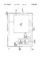
- FIG. 1is a block diagram of a chip temperature protection system.
- FIG. 2is a detailed block diagram of the chip temperature protection system of FIG. 1.
- FIG. 3is a block diagram of the chip temperature protection system within a design including a clock generator.
- FIG. 1shows a functional block diagram of a chip temperature protection system.
- the temperature protection systemcomprises a chip temperature monitor 10 and a comparator 20 located on the same silicon substrate and having close physical proximity to the chip logic functions. Therefore, the logic elements within the chip temperature monitor 10 are subjected to the same temperature conditions as the chip logic functions.
- the chip temperature protection systemmay be a separate entity located in close physical proximity to a chip's logic functions.
- the chip temperature monitor 10is supplied with a clock input signal.
- This clock input signalis shown supplied from an off-chip source, but may be supplied from an on-chip source which can provide a logic "high" input to the chip temperature monitor 10.
- the voltage of the input signalshould be kept constant.
- Chip temperature monitor 10determines the chip operating temperature and outputs this value to comparator 20.
- Comparator 20compares the current temperature to a predetermined operating range of temperatures. If the current temperature is outside the predetermined operating range, an alert signal is output to other devices. Details of the chip temperature protection system are shown in FIG. 2.
- the chip temperature monitor 10comprises a delay line 12, shown outlined by dashed lines.
- Each of the individual delay cells Dcomprises a pair of serially connected inverters. The propagation delay time of the delay cells varies with temperature.
- CMOS and other processing technologiesprovide greater density of devices on chips
- long strings of cascaded inverterscan be obtained at lower and lower cost and the inverters can be used as the basic high resolution unit delay element.
- other logic elementsmay also be used as the basic delay element without departing from the concept of the invention. Examples of cascaded inverters used as high resolution delay elements are in U.S. Pat. Nos. 5,451,894 and 5,457,719, both assigned to the assignee of the present invention.
- the number of delay cells N in delay line 12is chosen by the system designer and is dependent on the desired accuracy of the chip temperature monitor 10. For example, the greater the number N, the less the error will be in determining the delay time of each delay cell.
- the counter 14receives a start input from the input tap of the delay line at the input to D1 and begins counting. The counter 14 continues counting until the output stop signal from the output tap of the delay line at DN stops the counter 14.
- the counter 14contains a value which is equal to the propagation time of a signal through N delay cells. The counter 14 outputs this value to logic block 16.
- Logic block 16divides the total propagation time t, received from the counter, by N, where N is the number of serially connected delay cells in the delay line 12. The result of this calculation is the actual propagation delay time of a single delay cell at the current temperature.
- the counter 14may include logic to perform the calculations performed by logic block 16.
- the counter 14can be any one of many conventional counter devices which are known in the art.
- the counteris shown on-chip, but alternatively could be located off-chip.
- One alternative delay cell timing mechanismincludes a delay line oscillator. Using the known propagation delay time t for standard operating conditions, a system designer builds an oscillator by cascading N delay cells together to generate a clock signal with a known period. In order to determine the actual propagation delay of the delay cells based on the particular temperature conditions on the chip, a frequency comparator compares the output of the delay line oscillator to an external reference clock with a known frequency. By comparing the two clock signals, the actual propagation time t can be easily calculated.
- the delay cells in the delay line 12may be assigned addresses, as described in U.S. Pat. No. 5,457,719, assigned to the assignee of the present invention. This use of addressing enables logic block 16 and counter 14 to quickly know the length of the delay line and facilitates calculations made by logic block 16 or counter 14.
- Logic block 16determines the chip operating temperature from the actual propagation time t.
- Logic block 16contains a table of stored temperatures which correlate to various propagation times. For example, it may be known that a propagation time of 140 picoseconds for a single delay cell corresponds to a temperature of X° Celsius (C) at a constant voltage.
- Logic block 16stores the information that a delay time of 140 picoseconds corresponds to a chip temperature of X° C. Therefore, whenever the propagation time of a signal through a single delay cell is found to be 140 picoseconds, logic block 16 outputs a temperature value of X° C. to comparator 20.
- logic block 16may simply provide an indication that can be read from an external device to indicate the current temperature to a pre-assigned designated accuracy and/or time period.
- the propagation times for the various temperature values in logic block 16are generated under controlled conditions. These propagation times are generated experimentally by subjecting the chip through a range of temperature values and determining the corresponding propagation delay times. Other variables, such as voltage are kept constant throughout this process.
- the experimental rangeincludes temperature values above which and below which the chip will fail to perform properly or crash.
- a memory 18may be coupled to logic block 16 to store the temperature values on the chip at various times. In this manner, memory 18 contains an operating history of temperature values of the chip.
- Logic block 16outputs its information to comparator 20.
- Comparator 20compares the received temperature value to a range of operating temperatures for the chip. This operating range is known by the system designer and is dependent upon the operating conditions that the particular integrated circuit device can function at. This range is stored in comparator 20. Alternatively, the operating range could be stored elsewhere, such as in chip temperature monitor 10.
- logic block 16determines that the chip is operating at a temperature of Y° C.
- Comparator 20compares this temperature to the range of operating temperatures for the chip. If Y° C. is not within the predetermined range, comparator 20 outputs an alert signal indicating that the chip is operating outside its operating limits.
- the alert signalmay be coupled to an annunciator which provides an audible/visual signal that the chip is operating outside its operational temperature range. This alerts a person/system monitoring the chip that a temperature problem exists.
- the alert signalmay be coupled to a chip or system shutdown device.
- the chip shutdown devicereceives the alert signal and proceeds to shut down the operations of all the logic functions on the chip.
- a system shutdown devicereceives the alert signal and proceeds to shut down the operations of the system in which the chip is a part.
- the systemmay consist of a printed circuit (PC) board of interconnected chips. The entire PC board may be shut down when the chip temperature of the single chip is outside its operational limits.
- PCprinted circuit
- shutdown devicesprevent the chip from outputting erroneous results to other chips or systems.
- the details of the particular shutdown devicesare not needed for the present invention. Any known device which accepts an alert input signal and proceeds to suspend operation of the chip(s) is suitable for use in the invention.
- One examplemay couple the alert signal to a power switch which cuts power to the chip(s).
- comparator 20signals other chips/systems which it communicates with so that these chips/systems can take appropriate measures to avoid using potentially erroneous information from the chip which has exceeded its operating temperature.
- the output alert signal from the temperature protection deviceis input to a control system.
- the control systemtries to reduce the temperature by increasing the air flow in the enclosure containing the chip. This is done by controlling a fan(s) supplying air flow to the chip enclosure.
- the alert signalis a shutdown signal, the control system reduces the air flow in the chip enclosure since the chip is no longer operating.
- the chip temperature protection systemis shown integrated into a design which includes a delay line clock generator 22. Assume that the temperature of the chip is near its upper threshold, the alert signal is input to the delay line clock generator 22 to reduce the clock speed.
- the delay line clock generator 22adjusts the optimum operating frequency of the chip logic functions by a predetermined amount based on receiving the alert signal since optimum chip conditions no longer exist. From FIG. 3, it is seen that the chip temperature protection system can be readily integrated into a digital design and does not require much increased processing or chip space.
- the alert signalmay be used to adjust other internal timing devices or delay devices.
- Describedhas been a system and method for protecting the operation of an integrated circuit chip based on the chip temperature. Advantages of the invention are that the protection device requires no additional semiconductor processing steps, minimal additional processing overhead and consumes little space on the chip. Another advantage of the invention is that the protection device uses only standard logic cells that can be readily integrated with the digital functions on the chip.
Landscapes
- Semiconductor Integrated Circuits (AREA)
Abstract
Description
Claims (25)
Priority Applications (1)
| Application Number | Priority Date | Filing Date | Title |
|---|---|---|---|
| US08/914,263US5943206A (en) | 1997-08-19 | 1997-08-19 | Chip temperature protection using delay lines |
Applications Claiming Priority (1)
| Application Number | Priority Date | Filing Date | Title |
|---|---|---|---|
| US08/914,263US5943206A (en) | 1997-08-19 | 1997-08-19 | Chip temperature protection using delay lines |
Publications (1)
| Publication Number | Publication Date |
|---|---|
| US5943206Atrue US5943206A (en) | 1999-08-24 |
Family
ID=25434101
Family Applications (1)
| Application Number | Title | Priority Date | Filing Date |
|---|---|---|---|
| US08/914,263Expired - LifetimeUS5943206A (en) | 1997-08-19 | 1997-08-19 | Chip temperature protection using delay lines |
Country Status (1)
| Country | Link |
|---|---|
| US (1) | US5943206A (en) |
Cited By (20)
| Publication number | Priority date | Publication date | Assignee | Title |
|---|---|---|---|---|
| US6438503B1 (en)* | 1999-05-07 | 2002-08-20 | Oak Technology, Inc. | Estimation of device temperature |
| US20030210505A1 (en)* | 2002-05-13 | 2003-11-13 | Infineon Technologies North America Corp. | Use of an on-die temperature sensing scheme for thermal protection of DRAMS |
| US6702457B1 (en)* | 2001-12-20 | 2004-03-09 | National Semiconductor Corporation | Method and apparatus for a thermal wake-up circuit |
| US20070005290A1 (en)* | 2005-06-30 | 2007-01-04 | International Business Machines Corporation | Method and apparatus for monitoring integrated circuit temperature through deterministic path delays |
| US20070255966A1 (en)* | 2006-05-01 | 2007-11-01 | Vincenzo Condorelli | Cryptographic circuit with voltage-based tamper detection and response circuitry |
| US7356720B1 (en)* | 2003-01-30 | 2008-04-08 | Juniper Networks, Inc. | Dynamic programmable delay selection circuit and method |
| US20080162759A1 (en)* | 1997-10-10 | 2008-07-03 | Rambus Inc. | Method and apparatus for adjusting the performance of a synchronous memory system |
| US20090262468A1 (en)* | 2005-09-16 | 2009-10-22 | Rohm Co., Ltd. | Temperature protection circuit, power supply, and electronic device |
| US20100049995A1 (en)* | 2008-08-20 | 2010-02-25 | International Business Machines Corporation | Enhanced Thermal Management for Improved Module Reliability |
| US20100049466A1 (en)* | 2008-08-20 | 2010-02-25 | International Business Machines Corporation | Tracking Thermal Mini-Cycle Stress |
| US20110071725A1 (en)* | 2009-09-23 | 2011-03-24 | Ford Global Technologies, Llc | Remotely interacting with a vehicle to perform servicing and engineering functions from a nomadic device or computer |
| US20110071720A1 (en)* | 2009-09-21 | 2011-03-24 | Ford Global Technologies, Llc | Methods and systems for monitoring the condition of vehicle components from a nomadic wireless device or computer |
| US20110071734A1 (en)* | 2009-09-23 | 2011-03-24 | Ford Global Technologies, Llc | System and method for remotely controlling vehicle components from a nomadic communication device or computer |
| US20110080282A1 (en)* | 2009-10-01 | 2011-04-07 | Ford Global Technologies, Llc | Vehicle system passive notification using remote device |
| US20110205047A1 (en)* | 2010-02-25 | 2011-08-25 | Ford Global Technologies, Llc | Methods and systems for determining a tire pressure status |
| US20110205040A1 (en)* | 2010-02-25 | 2011-08-25 | Ford Global Technologies, Llc | Method and systems for detecting an unauthorized use of a vehicle by an authorized driver |
| US20110215901A1 (en)* | 2010-03-08 | 2011-09-08 | Ford Global Technologies, Llc | Method and system for enabling an authorized vehicle driveaway |
| US20110230165A1 (en)* | 2010-03-19 | 2011-09-22 | Ford Global Technologies, Llc | Wireless vehicle tracking |
| US9845097B2 (en) | 2015-08-12 | 2017-12-19 | Ford Global Technologies, Llc | Driver attention evaluation |
| US10099700B2 (en) | 2014-04-30 | 2018-10-16 | Ford Global Technologies, Llc | Method and system for driver tailored interaction time alert |
Citations (14)
| Publication number | Priority date | Publication date | Assignee | Title |
|---|---|---|---|---|
| US4980586A (en)* | 1987-10-07 | 1990-12-25 | Tektronix, Inc. | Digital integrated circuit propagation delay regulator |
| US5132572A (en)* | 1991-08-12 | 1992-07-21 | Advanced Micro Devices, Inc. | High-speed CMOS-to-ECL translator circuit |
| US5187632A (en)* | 1991-07-09 | 1993-02-16 | Daimler-Benz Ag | Controllable semiconductor switching device having integrated current limitation and overheating disconnection |
| US5220216A (en)* | 1992-01-02 | 1993-06-15 | Woo Ann K | Programmable driving power of a CMOS gate |
| US5227679A (en)* | 1992-01-02 | 1993-07-13 | Advanced Micro Devices, Inc. | Cmos digital-controlled delay gate |
| US5264745A (en)* | 1992-08-28 | 1993-11-23 | Advanced Micro Devices, Inc. | Recovering phase and data from distorted duty cycles caused by ECL-to-CMOS translator |
| US5349612A (en)* | 1992-06-19 | 1994-09-20 | Advanced Micro Devices, Inc. | Digital serializer and time delay regulator |
| US5363419A (en)* | 1992-04-24 | 1994-11-08 | Advanced Micro Devices, Inc. | Dual phase-locked-loop having forced mid range fine control zero at handover |
| US5367542A (en)* | 1992-06-19 | 1994-11-22 | Advanced Micro Devices, Inc. | Digital data recovery using delay time rulers |
| US5400370A (en)* | 1993-02-24 | 1995-03-21 | Advanced Micro Devices Inc. | All digital high speed algorithmic data recovery method and apparatus using locally generated compensated broad band time rulers and data edge position averaging |
| US5451894A (en)* | 1993-02-24 | 1995-09-19 | Advanced Micro Devices, Inc. | Digital full range rotating phase shifter |
| US5452333A (en)* | 1992-06-19 | 1995-09-19 | Advanced Micro Devices, Inc. | Digital jitter correction method and signal preconditioner |
| US5457719A (en)* | 1993-08-11 | 1995-10-10 | Advanced Micro Devices Inc. | All digital on-the-fly time delay calibrator |
| US5457336A (en)* | 1994-10-13 | 1995-10-10 | Advanced Micro Devices, Inc. | Non-volatile memory structure including protection and structure for maintaining threshold stability |
- 1997
- 1997-08-19USUS08/914,263patent/US5943206A/ennot_activeExpired - Lifetime
Patent Citations (14)
| Publication number | Priority date | Publication date | Assignee | Title |
|---|---|---|---|---|
| US4980586A (en)* | 1987-10-07 | 1990-12-25 | Tektronix, Inc. | Digital integrated circuit propagation delay regulator |
| US5187632A (en)* | 1991-07-09 | 1993-02-16 | Daimler-Benz Ag | Controllable semiconductor switching device having integrated current limitation and overheating disconnection |
| US5132572A (en)* | 1991-08-12 | 1992-07-21 | Advanced Micro Devices, Inc. | High-speed CMOS-to-ECL translator circuit |
| US5220216A (en)* | 1992-01-02 | 1993-06-15 | Woo Ann K | Programmable driving power of a CMOS gate |
| US5227679A (en)* | 1992-01-02 | 1993-07-13 | Advanced Micro Devices, Inc. | Cmos digital-controlled delay gate |
| US5363419A (en)* | 1992-04-24 | 1994-11-08 | Advanced Micro Devices, Inc. | Dual phase-locked-loop having forced mid range fine control zero at handover |
| US5349612A (en)* | 1992-06-19 | 1994-09-20 | Advanced Micro Devices, Inc. | Digital serializer and time delay regulator |
| US5367542A (en)* | 1992-06-19 | 1994-11-22 | Advanced Micro Devices, Inc. | Digital data recovery using delay time rulers |
| US5452333A (en)* | 1992-06-19 | 1995-09-19 | Advanced Micro Devices, Inc. | Digital jitter correction method and signal preconditioner |
| US5264745A (en)* | 1992-08-28 | 1993-11-23 | Advanced Micro Devices, Inc. | Recovering phase and data from distorted duty cycles caused by ECL-to-CMOS translator |
| US5400370A (en)* | 1993-02-24 | 1995-03-21 | Advanced Micro Devices Inc. | All digital high speed algorithmic data recovery method and apparatus using locally generated compensated broad band time rulers and data edge position averaging |
| US5451894A (en)* | 1993-02-24 | 1995-09-19 | Advanced Micro Devices, Inc. | Digital full range rotating phase shifter |
| US5457719A (en)* | 1993-08-11 | 1995-10-10 | Advanced Micro Devices Inc. | All digital on-the-fly time delay calibrator |
| US5457336A (en)* | 1994-10-13 | 1995-10-10 | Advanced Micro Devices, Inc. | Non-volatile memory structure including protection and structure for maintaining threshold stability |
Cited By (41)
| Publication number | Priority date | Publication date | Assignee | Title |
|---|---|---|---|---|
| US20080162759A1 (en)* | 1997-10-10 | 2008-07-03 | Rambus Inc. | Method and apparatus for adjusting the performance of a synchronous memory system |
| US8296540B2 (en)* | 1997-10-10 | 2012-10-23 | Rambus Inc. | Method and apparatus for adjusting the performance of a synchronous memory system |
| US6438503B1 (en)* | 1999-05-07 | 2002-08-20 | Oak Technology, Inc. | Estimation of device temperature |
| US6702457B1 (en)* | 2001-12-20 | 2004-03-09 | National Semiconductor Corporation | Method and apparatus for a thermal wake-up circuit |
| US20030210505A1 (en)* | 2002-05-13 | 2003-11-13 | Infineon Technologies North America Corp. | Use of an on-die temperature sensing scheme for thermal protection of DRAMS |
| US6873509B2 (en)* | 2002-05-13 | 2005-03-29 | Infineon Technologies Ag | Use of an on-die temperature sensing scheme for thermal protection of DRAMS |
| US8082463B2 (en) | 2003-01-30 | 2011-12-20 | Juniper Networks, Inc. | Dynamic programmable delay selection circuit and method |
| US7356720B1 (en)* | 2003-01-30 | 2008-04-08 | Juniper Networks, Inc. | Dynamic programmable delay selection circuit and method |
| US7849346B1 (en) | 2003-01-30 | 2010-12-07 | Juniper Networks, Inc. | Dynamic programmable delay selection circuit and method |
| US20110047402A1 (en)* | 2003-01-30 | 2011-02-24 | Juniper Networks, Inc. | Dynamic programmable delay selection circuit and method |
| US7275011B2 (en) | 2005-06-30 | 2007-09-25 | International Business Machines Corporation | Method and apparatus for monitoring integrated circuit temperature through deterministic path delays |
| US20070005290A1 (en)* | 2005-06-30 | 2007-01-04 | International Business Machines Corporation | Method and apparatus for monitoring integrated circuit temperature through deterministic path delays |
| US7961446B2 (en)* | 2005-09-16 | 2011-06-14 | Rohm Co., Ltd. | Temperature protection circuit, power supply, and electronic device |
| US20090262468A1 (en)* | 2005-09-16 | 2009-10-22 | Rohm Co., Ltd. | Temperature protection circuit, power supply, and electronic device |
| US20070255966A1 (en)* | 2006-05-01 | 2007-11-01 | Vincenzo Condorelli | Cryptographic circuit with voltage-based tamper detection and response circuitry |
| US7917328B2 (en) | 2008-08-20 | 2011-03-29 | International Business Machines Corporation | Tracking thermal mini-cycle stress |
| US20100049466A1 (en)* | 2008-08-20 | 2010-02-25 | International Business Machines Corporation | Tracking Thermal Mini-Cycle Stress |
| US20100049995A1 (en)* | 2008-08-20 | 2010-02-25 | International Business Machines Corporation | Enhanced Thermal Management for Improved Module Reliability |
| US8214658B2 (en) | 2008-08-20 | 2012-07-03 | International Business Machines Corporation | Enhanced thermal management for improved module reliability |
| US20110071720A1 (en)* | 2009-09-21 | 2011-03-24 | Ford Global Technologies, Llc | Methods and systems for monitoring the condition of vehicle components from a nomadic wireless device or computer |
| US11270233B2 (en) | 2009-09-21 | 2022-03-08 | Ford Global Technologies, Llc | Methods and systems for monitoring the condition of vehicle components from a nomadic wireless device or computer |
| US9715665B2 (en) | 2009-09-21 | 2017-07-25 | Ford Global Technologies, Llc | Methods and systems for monitoring the condition of vehicle components from a nomadic wireless device or computer |
| US20110071734A1 (en)* | 2009-09-23 | 2011-03-24 | Ford Global Technologies, Llc | System and method for remotely controlling vehicle components from a nomadic communication device or computer |
| US20110071725A1 (en)* | 2009-09-23 | 2011-03-24 | Ford Global Technologies, Llc | Remotely interacting with a vehicle to perform servicing and engineering functions from a nomadic device or computer |
| US8346432B2 (en) | 2009-09-23 | 2013-01-01 | Ford Global Technologies, Llc | System and method for remotely controlling vehicle components from a nomadic communication device or computer |
| US8558690B2 (en)* | 2009-10-01 | 2013-10-15 | Ford Global Technologies, Llc | Vehicle system passive notification using remote device |
| US9251694B2 (en) | 2009-10-01 | 2016-02-02 | Ford Global Technologies, Llc | Vehicle system passive notification using remote device |
| US20110080282A1 (en)* | 2009-10-01 | 2011-04-07 | Ford Global Technologies, Llc | Vehicle system passive notification using remote device |
| US9205710B2 (en) | 2010-02-25 | 2015-12-08 | Ford Global Technologies, Llc | Methods and systems for determining a tire pressure status |
| US8558678B2 (en) | 2010-02-25 | 2013-10-15 | Ford Global Technologies, Llc | Method and systems for detecting an unauthorized use of a vehicle by an authorized driver |
| US20110205040A1 (en)* | 2010-02-25 | 2011-08-25 | Ford Global Technologies, Llc | Method and systems for detecting an unauthorized use of a vehicle by an authorized driver |
| US8525657B2 (en) | 2010-02-25 | 2013-09-03 | Ford Global Technologies, Llc | Methods and systems for determining a tire pressure status |
| US20110205047A1 (en)* | 2010-02-25 | 2011-08-25 | Ford Global Technologies, Llc | Methods and systems for determining a tire pressure status |
| US8614622B2 (en) | 2010-03-08 | 2013-12-24 | Ford Global Technologies, Llc | Method and system for enabling an authorized vehicle driveaway |
| US9205807B2 (en) | 2010-03-08 | 2015-12-08 | Ford Global Technologies, Llc | Method and system for enabling an authorized vehicle driveaway |
| US9580044B2 (en) | 2010-03-08 | 2017-02-28 | Ford Global Technologies, Llc | Method and system for enabling an authorized vehicle driveaway |
| US20110215901A1 (en)* | 2010-03-08 | 2011-09-08 | Ford Global Technologies, Llc | Method and system for enabling an authorized vehicle driveaway |
| US20110230165A1 (en)* | 2010-03-19 | 2011-09-22 | Ford Global Technologies, Llc | Wireless vehicle tracking |
| US10075806B2 (en) | 2010-03-19 | 2018-09-11 | Ford Global Technologies, Llc | Wireless vehicle tracking |
| US10099700B2 (en) | 2014-04-30 | 2018-10-16 | Ford Global Technologies, Llc | Method and system for driver tailored interaction time alert |
| US9845097B2 (en) | 2015-08-12 | 2017-12-19 | Ford Global Technologies, Llc | Driver attention evaluation |
Similar Documents
| Publication | Publication Date | Title |
|---|---|---|
| US5943206A (en) | Chip temperature protection using delay lines | |
| US5890100A (en) | Chip temperature monitor using delay lines | |
| US6695475B2 (en) | Temperature sensing circuit and method | |
| EP0432925B1 (en) | Method and apparatus for sensing thermal stress in integrated circuits | |
| US10302502B2 (en) | Determining rate of change in temperature measurements | |
| US7149645B2 (en) | Method and apparatus for accurate on-die temperature measurement | |
| US5852616A (en) | On-chip operating condition recorder | |
| KR950030486A (en) | Power-on reset circuit | |
| US6674623B1 (en) | Microcomputer equipped with built-in temperature sensor | |
| KR970076849A (en) | Integrated circuit with speed detector | |
| US5278457A (en) | Method and apparatus for adjusting clock signal of electronic apparatus | |
| US5526486A (en) | Apparatus for detecting undefined states of a finite state machine (FSM) and resetting the FSM upon detection | |
| US7106116B2 (en) | Pulse duty deterioration detection circuit | |
| US7275011B2 (en) | Method and apparatus for monitoring integrated circuit temperature through deterministic path delays | |
| CN111030036A (en) | Circuit with critical operating condition alarm, corresponding device and method | |
| JP3579109B2 (en) | Power supply monitoring circuit for CPU | |
| US20050261866A1 (en) | Thermal protection for a VLSI chip through reduced c4 usage | |
| JPS61105629A (en) | Clock control method | |
| KR20060003434A (en) | Semiconductor memory device having over-stress detection function and semiconductor memory system comprising same | |
| JPH11330931A (en) | Apparatus and method for monitoring clock operation in control system | |
| KR940007908B1 (en) | Abnormal state detection circuit of multiple sensors | |
| KR960000157B1 (en) | An apparatus supervising a central office-voice data multiplexer circuit pack | |
| KR920006325B1 (en) | Automatic state detection circuit of microprocessor control system | |
| JPH0674833A (en) | Temperature detecting circuit | |
| KR940009828B1 (en) | Pulse input module for controlling automation |
Legal Events
| Date | Code | Title | Description |
|---|---|---|---|
| AS | Assignment | Owner name:ADVANCED MICRO DEVICES, INC., CALIFORNIA Free format text:ASSIGNMENT OF ASSIGNORS INTEREST;ASSIGNOR:CRAYFORD, IAN;REEL/FRAME:008758/0155 Effective date:19970818 | |
| STCF | Information on status: patent grant | Free format text:PATENTED CASE | |
| CC | Certificate of correction | ||
| FPAY | Fee payment | Year of fee payment:4 | |
| FPAY | Fee payment | Year of fee payment:8 | |
| AS | Assignment | Owner name:GLOBALFOUNDRIES INC., CAYMAN ISLANDS Free format text:ASSIGNMENT OF ASSIGNORS INTEREST;ASSIGNOR:AMD TECHNOLOGIES HOLDINGS, INC.;REEL/FRAME:022764/0544 Effective date:20090302 Owner name:AMD TECHNOLOGIES HOLDINGS, INC., CALIFORNIA Free format text:ASSIGNMENT OF ASSIGNORS INTEREST;ASSIGNOR:ADVANCED MICRO DEVICES, INC.;REEL/FRAME:022764/0488 Effective date:20090302 | |
| FPAY | Fee payment | Year of fee payment:12 | |
| AS | Assignment | Owner name:GLOBALFOUNDRIES U.S. INC., NEW YORK Free format text:RELEASE BY SECURED PARTY;ASSIGNOR:WILMINGTON TRUST, NATIONAL ASSOCIATION;REEL/FRAME:056987/0001 Effective date:20201117 |