US5943149A - Optical multiplexor/demultiplexor using a narrow band filter followed by a wideband filter - Google Patents
Optical multiplexor/demultiplexor using a narrow band filter followed by a wideband filterDownload PDFInfo
- Publication number
- US5943149A US5943149AUS09/025,468US2546898AUS5943149AUS 5943149 AUS5943149 AUS 5943149AUS 2546898 AUS2546898 AUS 2546898AUS 5943149 AUS5943149 AUS 5943149A
- Authority
- US
- United States
- Prior art keywords
- channels
- channel
- filter
- wavelength
- optical
- Prior art date
- Legal status (The legal status is an assumption and is not a legal conclusion. Google has not performed a legal analysis and makes no representation as to the accuracy of the status listed.)
- Expired - Lifetime
Links
- 230000003287optical effectEffects0.000titleclaimsabstractdescription54
- 238000001914filtrationMethods0.000claimsdescription7
- 238000000034methodMethods0.000claimsdescription6
- 239000013307optical fiberSubstances0.000description13
- 238000005516engineering processMethods0.000description11
- 239000000758substrateSubstances0.000description9
- 238000010586diagramMethods0.000description6
- 239000000835fiberSubstances0.000description5
- 238000002955isolationMethods0.000description4
- 230000005540biological transmissionEffects0.000description3
- 230000002238attenuated effectEffects0.000description2
- 230000006854communicationEffects0.000description2
- 238000004891communicationMethods0.000description2
- 239000003989dielectric materialSubstances0.000description2
- 230000000694effectsEffects0.000description2
- 238000003780insertionMethods0.000description2
- 230000037431insertionEffects0.000description2
- 108091081062Repeated sequence (DNA)Proteins0.000description1
- 238000004026adhesive bondingMethods0.000description1
- 230000007175bidirectional communicationEffects0.000description1
- 230000002457bidirectional effectEffects0.000description1
- BJQHLKABXJIVAM-UHFFFAOYSA-Nbis(2-ethylhexyl) phthalateChemical compoundCCCCC(CC)COC(=O)C1=CC=CC=C1C(=O)OCC(CC)CCCCBJQHLKABXJIVAM-UHFFFAOYSA-N0.000description1
- 230000002708enhancing effectEffects0.000description1
- 239000011521glassSubstances0.000description1
Images


Classifications
- H—ELECTRICITY
- H04—ELECTRIC COMMUNICATION TECHNIQUE
- H04J—MULTIPLEX COMMUNICATION
- H04J14/00—Optical multiplex systems
- H04J14/02—Wavelength-division multiplex systems
- H04J14/03—WDM arrangements
- H04J14/0307—Multiplexers; Demultiplexers
Definitions
- This inventionrelates generally to optical filters and more particularly to an arrangement of optical filters for multiplexing and/or demultiplexing optical signals wherein power losses and differences in power loss for different channels usually associated with such demultiplexors is substantially lessened.
- Optical systemsare presently being employed in the communication of voice and video information as well as in the high-speed transmission of data. Optical communication systems are desired because of the wide bandwidth available for the information signal channels.
- WDMwavelength division multiplexing
- these channelsWhen a number of wavelengths are multiplexed and transmitted on a single optical fiber, customarily, these channels must later be demultiplexed into separate channels or wavelengths of light. For example, it may be cost effective to transmit signals of wavelength ⁇ 1, ⁇ 2, ⁇ 3, ⁇ 4, ⁇ 5, and ⁇ 6 ( ⁇ denoting a wavelength, lambda) along a single optical fiber, however, demultiplexing means are required to separate the light into six separate channels. Of course, it is desired to perform this demultiplexing at a minimum cost and with as little signal loss as possible. Furthermore, if signal loss exists, it is important for any signal loss present on any channel to be of a similar magnitude for all channels being demultiplexed.
- WDM filtersThere are several technologies that can be used to construct WDM filters. For example, etalon technology, diffraction grading technology, fused biconic taper technology, and holographic filter technology.
- etalon technologydiffraction grading technology
- fused biconic taper technologyfused biconic taper technology
- holographic filter technologyOne technology that has proven to be widely useful in the telecommunications industry is dichroic filter technology. This technology offers wide channel passbands, flat channel passbands, low insertion loss, moderate isolation, low cost, high reliability and field ruggedness, high thermal stability, and moderate filter roll-off characteristics.
- a dichroic filter 300is comprised of one or more layers of dielectric material coated onto a, for example, glass substrate 305 with lenses 310 to focus the incoming and outgoing optical signals.
- the choice of dielectric material, the number of dielectric layers coated onto the substrate, and the spacing of these layersare chosen to provide the appropriate transmissive and reflective properties for a given "target" wavelength.
- the number and spacing of the dielectric layers on the substrate 305would be chosen to provide (1) a specified passband tolerance around ⁇ 1 and (2) the necessary isolation requirements for all other transmitted wavelengths, for example, a wavelength, ⁇ 2, transmitted by a second transmitter.
- the dichroic, or WDM, filteris constructed by placing self-focusing lenses, such as "SELFOC” lenses 310, on either side of the dielectric substrate 305.
- SELFOCself-focusing lenses
- "SELFOC” lens 310collimates incoming light ( ⁇ 1 and ⁇ 2) at the dielectric substrate.
- Attached to the "SELFOC" lenses through an adhesive bonding processare, typically, single-mode optical fibers.
- the locations at which optical fibers attach to the "SELFOC" lenses 310are called ports: port 1 320, port 2 325, and port 3 330.
- Connected to the portsare optical fibers 335, 340, and 345 respectively.
- all of the light (comprised of ⁇ 1 and ⁇ 2) passing through fiber 335 connected to port 1 320is collimated by lens 310 at the dielectric substrate 305.
- the substrateSince the substrate is coated to pass wavelengths around ⁇ 1, virtually all of the light at ⁇ 1 passes through the dielectric substrate 305 and, via the second "SELFOC” lens, is focused into port 3 330, and passes away from the filter on optical fiber 345. Any other wavelength incident on the filter through port 1 320 (e.g., light of wavelength ⁇ 2) is reflected off the multi-layer substrate, focused back through the first "SELFOC" lens to port 2 325, and passes away from the filter on optical fiber 340. Likewise, the filter performs the same function for light traveling in the opposite direction.
- channel 2which must encounter two filter elements prior to be being removed or demultiplexed from the multiplexed signal channels undergoes less loss, than for example, channel 16 which encounters 16 filter interfaces.
- a demultiplexorseparates a group of channels into individual channels losses for each channel should most importantly be minimal and it is preferable that any losses introduced by the system should be as near to equal as possible for all channels. This is not the case with conventional demultiplexor designs using a conventional arrangement of cascaded narrow band dichroic filters.
- an optical filter arrangementfor demultiplexing an optical signal having a plurality of channels, said filter arrangement comprising at least two filters, at least a first optical filter for separating a group of channels into a lower and a higher wavelength group of channels, each group comprising a plurality of channels, and a second optical filter for filtering and separating from the optical signal at least one channel having a central wavelength between the lower and the higher wavelength groups of channels, the at least two filters being optically coupled to one another such that the at least a channel between the lower and higher wavelength group of channels is first removed from the optical signal by the second filter before said lower or higher wavelength groups of channels are removed by the first optical filter respectively.
- an optical demultiplexorfor demultiplexing an optical signal having at least n sequential channels into a plurality of channel groupings, wherein n >3, each channel having a different central wavelength, each of n-1 of the n channels having lower central wavelength than a subsequent sequential channel, the n th channel having a highest central wavelength and the 1 st channel having the lowest central wavelength, said demultiplexor comprising:
- a plurality of sequentially, interconnected, optically-coupled, optical filtersincluding at least a narrow band filter for separating and removing at least a single channel having a central wavelength corresponding to a channel between the 1 st and the n th channel from the plurality of channels and at least a filter for separating at least two groups of different channels adjacent the single channel after the single channel has been removed, a first of the two groups of channels having central wavelengths below the wavelength of the at least single channel, and a second of the two groups having central wavelengths above the wavelength of the at least single channel.
- an optical filter arrangementcomprising a plurality of filters said filters including at least a narrow band filter and a wide band filter, the narrow band filter disposed to first filter a narrow wavelength band of light and the wide band filter disposed to subsequently filter and separate wide wavelength bands of light.
- method of demultiplexing a plurality of sequential channels from an optical signalcomprising the steps of: first filtering a narrow band channel having a wavelength that is substantially in the middle of a range of wavelengths of the plurality of sequential channels to remove the narrow band channel from the plurality of sequential channels; and, subsequently separating remaining channels into two groups of channels a first group having central wavelengths below the wavelength of the narrow band channel, and a second group having central wavelengths above the wavelength of the narrow band channel.
- FIG. 1is a schematic block diagram of a prior art multi-channel WDM wherein continuous cascading occurs
- FIG. 2ais a schematic block diagram of a multi-channel WDM wherein channels are separated into two banks prior to be further demultiplxed;
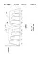
- FIG. 2bis a graph of an output response for the circuit shown in FIG. 2a;
- FIG. 3is a prior art schematic block diagram of a prior art 3-port dichroic WDM filter
- FIG. 4is a schematic block diagram of a system wherein a narrow band filter is first used to remove a single narrow band channel;
- FIG. 5is a schematic block diagram of a system wherein a single narrow band channel is first removed prior to demultiplexing two groups of channels simultaneously;
- FIG. 6schematic block diagram of a system wherein two narrow band channels are first removed prior to demultiplexing the remaining channels.
- FIG. 1shows a cascaded prior art circuit wherein dichroic filters 10a through 10n each having a different wavelength response are serially interconnected in a cascaded arrangement to demultiplex a multiplexed optical signal comprising channels 1 to n, corresponding to wavelengths ⁇ 1, ⁇ 2, ⁇ 3, . . . ⁇ n. Since there is a fixed power loss associated with each filter in transmission, and a fixed but lesser power loss associated with each filter in reflection, those signals that reflect from a plurality of filters, will be more attenuated than for example signals that reflect from one or fewer numbers of filters.
- the attenuation due to reflection of channel from nwill be n-2 times greater than the attenuation due to reflection loss of channel 2.
- serially cascading filtersis not preferred due to the large insertion loss for channels near the end of the series coupled filters, and furthermore, due the large differential channels loss, especially between channels at different ends of the series filters.
- FIG. 2aillustrates a cascaded demultiplexing/multiplexing optical system wherein a band splitter 20 first splits 16 channels into a first group of 8 channels comprising wavelengths ⁇ 1, ⁇ 2, . . . ⁇ 8, and a second group of channels comprising wavelengths ⁇ 10 . . . ⁇ 16.
- the first group of channelsis then presented to a first bank of cascaded filters 10a through 10h, similar to the arrangement shown if FIG. 1.
- the second group of channelsis simultaneously presented to a second bank of cascaded filters 10j through 10p.
- the response of the splitter 20is shown in dotted outline 30a and 30b. Since the splitter comprises two wide band filters, or alternatively a low and high pass filter having a less than ideal slope 32a and 32b, a channel is missed or lost, and channels on either side of the missing channel are separated into two streams as described above. The figure also illustrates how the first channel of each bank has greater amplitude than subsequent channels in that bank which are progressively attenuated.
- FIG. 4provides circuitry wherein a single narrow band channel between two banks of channels, is first removed or demultiplexed, leaving space for wide band filters (or a high and low pass filter) to separate the channels on either side into two groups for further filtering/demultiplexing.
- a narrow band filter 10i designed to transmit a single narrow band channel, in this instance, ⁇ 9is optically coupled with a band splitter 20 in the form of a band pass filter designed to transmit channels 1 to 8 along a straight through transmit path from port 1 to port 3 of the filter, and to reflect channels 10 to 16 along another path from port 1 to the filter element and back to port 2. Since the output response of the splitter 20 is such, that space is required between the channels being split to achieve high isolation, channel 9 having a central wavelength ⁇ 9 is first removed in this arrangement.
- FIG. 5shows yet an extension to this embodiment, wherein the optical circuit of FIG. 4 is combined with the optical circuit of FIG.
- the band splitting filtercould be in the form of band pass filters or high and low pass filters.
- the filtersare not required to have particularly steep slopes. If however the filters are very "sloppy", i.e. if the slopes are not very steep, it may be required to provide greater isolation than is afforded by the removal of one channel, and two channels can first be removed prior to splitting blocks of channels adjacent the two channels. This can be accomplished by first passing the multiplexed signal through two narrow band filters. This is shown in FIG. 6.
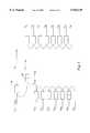
- channels 32 and 33are first dropped (or demultiplexed) by using two narrow band filters that are serially optically coupled. Subsequently, using wide band pass filters, or high and low pass filters, channels 1 to 31, and 34 to 64 are split into two groups of channels. Subsequent to providing two groups of channels, channels 1 to 31 are split in a similar fashion by using one or more narrow band filters to remove/demultiplex channel(s) 15 (and 16) and then channels 1 to 14 and 17 to 31 are separated into two sub-groups of channels.
- channels 34 to 64can be demultiplxed by this repeated sequence of first removing one or more centrally located channels using one or more narrow band filters, and then subsequently using wide band filters or high and low pass filters to remove or demultiplex groups of channels, which can subsequently be demultiplxed using cascaded narrow band filters.
- these schemesprovide a means of lessening overall signal losses by dividing long sequential chains of filters into a plurality of banks of filters.
- Bragg filtercan be used for separating a channel from the group of channels.
Landscapes
- Engineering & Computer Science (AREA)
- Computer Networks & Wireless Communication (AREA)
- Signal Processing (AREA)
- Optical Communication System (AREA)
Abstract
Description
Claims (17)
Priority Applications (4)
| Application Number | Priority Date | Filing Date | Title |
|---|---|---|---|
| US09/025,468US5943149A (en) | 1998-02-18 | 1998-02-18 | Optical multiplexor/demultiplexor using a narrow band filter followed by a wideband filter |
| CA002255346ACA2255346C (en) | 1998-02-18 | 1998-12-09 | Optical multiplexor/demultiplexor |
| EP99103022AEP0938205A3 (en) | 1998-02-18 | 1999-02-16 | Optical multiplexor/demultiplexor |
| JP11038437AJPH11337765A (en) | 1998-02-18 | 1999-02-17 | Optical demultiplexing method, optical filter arrangement system and optical filter device thereof |
Applications Claiming Priority (1)
| Application Number | Priority Date | Filing Date | Title |
|---|---|---|---|
| US09/025,468US5943149A (en) | 1998-02-18 | 1998-02-18 | Optical multiplexor/demultiplexor using a narrow band filter followed by a wideband filter |
Publications (1)
| Publication Number | Publication Date |
|---|---|
| US5943149Atrue US5943149A (en) | 1999-08-24 |
Family
ID=21826239
Family Applications (1)
| Application Number | Title | Priority Date | Filing Date |
|---|---|---|---|
| US09/025,468Expired - LifetimeUS5943149A (en) | 1998-02-18 | 1998-02-18 | Optical multiplexor/demultiplexor using a narrow band filter followed by a wideband filter |
Country Status (4)
| Country | Link |
|---|---|
| US (1) | US5943149A (en) |
| EP (1) | EP0938205A3 (en) |
| JP (1) | JPH11337765A (en) |
| CA (1) | CA2255346C (en) |
Cited By (30)
| Publication number | Priority date | Publication date | Assignee | Title |
|---|---|---|---|---|
| WO2000003277A1 (en)* | 1998-07-08 | 2000-01-20 | E-Tek Dynamics, Inc. | Improved add/drop wdm multiplexer for fiberoptic networks |
| WO2002019571A1 (en)* | 2000-08-25 | 2002-03-07 | R & Dm Foundation | Shared multi-channel optical interface |
| WO2002063363A1 (en)* | 2001-02-07 | 2002-08-15 | Redfern Broadband Networks Pty Ltd | Transparent optical-electronic-optical switch |
| US6452700B1 (en) | 2001-01-11 | 2002-09-17 | R&Dm Foundation | Computer backplane employing free space optical interconnect |
| US6483618B2 (en)* | 1999-11-30 | 2002-11-19 | Corning Incorporated | Narrow band wavelength division demultiplexer and method of demultiplexing optical signals |
| US20020181046A1 (en)* | 2001-04-10 | 2002-12-05 | Gazillion Bits, Inc. | Wavelength division multiplexing with narrow band reflective filters |
| US20020191254A1 (en)* | 2001-06-19 | 2002-12-19 | Robert Mays | Network routing employing free-space optical broadcasting |
| US20020191598A1 (en)* | 2001-06-19 | 2002-12-19 | Robert Mays | Network switch employing free-space optical switching technique |
| US20030117728A1 (en)* | 1999-11-24 | 2003-06-26 | Donnelly Corporation, A Corporation Of The State Of Michigan | Interior rearview mirror system including a pendent accessory |
| US20030175030A1 (en)* | 2002-03-18 | 2003-09-18 | Shuqiang Chen | Re-configurable optical add/drop multiplexer module and method |
| US20030185565A1 (en)* | 2002-01-18 | 2003-10-02 | Nec Usa, Inc | Non-uniform optical waveband aggregator and deaggregator and hierarchical hybrid optical cross-connect system |
| US6731830B2 (en) | 2001-01-05 | 2004-05-04 | Redfern Broadband Networks, Inc. | Asymmetric compatible network element |
| US6741393B1 (en)* | 2002-01-17 | 2004-05-25 | Raytheon Company | Optical system with optical frequency discriminator |
| US20040101307A1 (en)* | 1999-05-14 | 2004-05-27 | Fujitsu Limited | Optical device, terminal apparatus, and system for wavelength division multiplexing |
| US20040190896A1 (en)* | 2003-03-28 | 2004-09-30 | Fujitsu Limited | Multi-directional optical branching apparatus |
| US6853812B2 (en) | 2001-05-09 | 2005-02-08 | Robert Mays, Jr. | Polarized-holographic filtering providing improved extinction ratio |
| US6870976B2 (en)* | 2001-03-13 | 2005-03-22 | Opnext, Inc. | Filter based multiplexer/demultiplexer component |
| US20050100276A1 (en)* | 2003-11-06 | 2005-05-12 | Hideki Hashizume | Wavelength selective optical device and method of tuning a wavelength characteristic of the same |
| US20050129412A1 (en)* | 2003-12-12 | 2005-06-16 | Lucent Technologies Inc. | Method and apparatus for multi-band optical switching using multi-pump parametric devices |
| US6944406B1 (en) | 2000-08-04 | 2005-09-13 | Fujitsu Limited | Transport system with tunable channel spacing DWDM |
| US6973268B1 (en)* | 2000-06-30 | 2005-12-06 | Lucent Technologies Inc. | Bi-directional optical transmission using dual channel bands |
| US7043159B1 (en) | 1999-04-13 | 2006-05-09 | Nortel Networks Limited | Bidirectional optical networks |
| US7082267B1 (en) | 2000-08-25 | 2006-07-25 | R& Dm Foundation | Shared multi-channel parallel optical interface |
| US7280760B1 (en)* | 2002-08-28 | 2007-10-09 | Avanex Corporation | Upgradeable optical add/drop multiplexer |
| US20080013955A1 (en)* | 2004-05-26 | 2008-01-17 | Hoya Corporation | Optical Module and Optical Wavelength Multiplexing and Demultiplexing Device |
| US20080212966A1 (en)* | 2005-05-26 | 2008-09-04 | Matteo Costantini | Optimised Multiplexer/Demultiplexer Optical Structure |
| US20100278526A1 (en)* | 2006-10-27 | 2010-11-04 | Huawei Technologies Co., Ltd. | Optoelectronic Integrated Apparatus And Method For Protecting Optoelectronic Integrated Apparatus |
| US20160164625A1 (en)* | 2013-07-16 | 2016-06-09 | Commscope Technologies Llc | Distributed wave division multiplexing systems |
| US20170212006A9 (en)* | 2014-10-16 | 2017-07-27 | Alliance Fiber Optic Products, Inc. | High Isolation and High Return Loss 2-Port Optical Retro-Reflector |
| CN113866895A (en)* | 2020-06-30 | 2021-12-31 | 中国移动通信有限公司研究院 | A wavelength division multiplexing structure |
Families Citing this family (11)
| Publication number | Priority date | Publication date | Assignee | Title |
|---|---|---|---|---|
| ES2159239B1 (en)* | 1999-06-11 | 2002-04-16 | Televisio De Catalunya S A | OPTICAL FIBER TRANSMISSION SYSTEM. |
| JP2001221041A (en)* | 2000-02-07 | 2001-08-17 | Sanshin Ind Co Ltd | Muffler mounting structure of outboard motor |
| JP2002090573A (en) | 2000-07-10 | 2002-03-27 | Hoya Corp | Optical filter module and various optical devices using the same |
| US6519384B2 (en) | 2000-08-30 | 2003-02-11 | Telefonaktiebolaget Lm Ericsson (Publ) | Optical communication network |
| EP1185017A1 (en)* | 2000-08-30 | 2002-03-06 | Telefonaktiebolaget Lm Ericsson | An optical communication network |
| KR20040016406A (en) | 2002-08-15 | 2004-02-21 | 호야 가부시키가이샤 | Optical module |
| US20050095001A1 (en)* | 2003-10-29 | 2005-05-05 | Fujitsu Limited | Method and system for increasing network capacity in an optical network |
| KR100658338B1 (en) | 2004-04-09 | 2006-12-14 | 노베라옵틱스코리아 주식회사 | Wavelength Division Multiplexing Passive Fluorescent Network with Multistage Branch Light Distribution Network |
| FR2944360B1 (en)* | 2009-04-08 | 2011-11-25 | Alcatel Lucent | OPTICAL DEVICE FOR RECEIVING NON-CONVENTIONAL INTER-CHANNEL FREQUENCY SEPARATION |
| KR102284163B1 (en)* | 2018-09-21 | 2021-07-30 | 주식회사 옵티코어 | Multiplexer and Demultiplexer For Dense Wavelength Division Multiplex |
| KR102426671B1 (en)* | 2020-05-14 | 2022-07-29 | 주식회사 론텍 | A dual band cwdm pass filter module made by the complex of single band cwdm pass filters |
Citations (2)
| Publication number | Priority date | Publication date | Assignee | Title |
|---|---|---|---|---|
| US5629995A (en)* | 1996-02-01 | 1997-05-13 | Jds Fitel Inc. | Wavelength filter arrangements for use in fiber optics |
| US5652814A (en)* | 1994-12-21 | 1997-07-29 | E-Tek Dynamics, Inc. | Integrable fiberoptic coupler and resulting devices and systems |
Family Cites Families (1)
| Publication number | Priority date | Publication date | Assignee | Title |
|---|---|---|---|---|
| CA2229607A1 (en)* | 1995-08-29 | 1997-03-06 | Anthony S. Kewitsch | Wavelength selective grating assisted optical couplers |
- 1998
- 1998-02-18USUS09/025,468patent/US5943149A/ennot_activeExpired - Lifetime
- 1998-12-09CACA002255346Apatent/CA2255346C/ennot_activeExpired - Lifetime
- 1999
- 1999-02-16EPEP99103022Apatent/EP0938205A3/ennot_activeCeased
- 1999-02-17JPJP11038437Apatent/JPH11337765A/enactivePending
Patent Citations (2)
| Publication number | Priority date | Publication date | Assignee | Title |
|---|---|---|---|---|
| US5652814A (en)* | 1994-12-21 | 1997-07-29 | E-Tek Dynamics, Inc. | Integrable fiberoptic coupler and resulting devices and systems |
| US5629995A (en)* | 1996-02-01 | 1997-05-13 | Jds Fitel Inc. | Wavelength filter arrangements for use in fiber optics |
Cited By (49)
| Publication number | Priority date | Publication date | Assignee | Title |
|---|---|---|---|---|
| WO2000003277A1 (en)* | 1998-07-08 | 2000-01-20 | E-Tek Dynamics, Inc. | Improved add/drop wdm multiplexer for fiberoptic networks |
| US7043159B1 (en) | 1999-04-13 | 2006-05-09 | Nortel Networks Limited | Bidirectional optical networks |
| US20040101307A1 (en)* | 1999-05-14 | 2004-05-27 | Fujitsu Limited | Optical device, terminal apparatus, and system for wavelength division multiplexing |
| US20090005136A1 (en)* | 1999-11-24 | 2009-01-01 | Donnelly Corporation | Interior rearview mirror system with identifier module |
| US20060002123A1 (en)* | 1999-11-24 | 2006-01-05 | Hutzel Barry W | Rearview mirror assembly with utility functions |
| US20080080076A1 (en)* | 1999-11-24 | 2008-04-03 | Donnelly Corporation | Rearview mirror assembly with utility functions |
| US6902284B2 (en) | 1999-11-24 | 2005-06-07 | Donnelly Corporation | Interior rearview mirror system including a pendent accessory |
| US20030117728A1 (en)* | 1999-11-24 | 2003-06-26 | Donnelly Corporation, A Corporation Of The State Of Michigan | Interior rearview mirror system including a pendent accessory |
| US9827918B2 (en) | 1999-11-24 | 2017-11-28 | Donnelly Corporation | Forward facing imaging system |
| US6483618B2 (en)* | 1999-11-30 | 2002-11-19 | Corning Incorporated | Narrow band wavelength division demultiplexer and method of demultiplexing optical signals |
| US6973268B1 (en)* | 2000-06-30 | 2005-12-06 | Lucent Technologies Inc. | Bi-directional optical transmission using dual channel bands |
| US7092642B2 (en) | 2000-08-04 | 2006-08-15 | Fujitsu Limited | Tunable channel spacing for wavelength division multiplexing (WDM) transport system |
| US6944406B1 (en) | 2000-08-04 | 2005-09-13 | Fujitsu Limited | Transport system with tunable channel spacing DWDM |
| US7099590B2 (en) | 2000-08-25 | 2006-08-29 | R&Dm Foundation | Filtering technique for free space interconnects |
| US7082267B1 (en) | 2000-08-25 | 2006-07-25 | R& Dm Foundation | Shared multi-channel parallel optical interface |
| WO2002019571A1 (en)* | 2000-08-25 | 2002-03-07 | R & Dm Foundation | Shared multi-channel optical interface |
| US6731830B2 (en) | 2001-01-05 | 2004-05-04 | Redfern Broadband Networks, Inc. | Asymmetric compatible network element |
| US6452700B1 (en) | 2001-01-11 | 2002-09-17 | R&Dm Foundation | Computer backplane employing free space optical interconnect |
| WO2002063363A1 (en)* | 2001-02-07 | 2002-08-15 | Redfern Broadband Networks Pty Ltd | Transparent optical-electronic-optical switch |
| US6870976B2 (en)* | 2001-03-13 | 2005-03-22 | Opnext, Inc. | Filter based multiplexer/demultiplexer component |
| US6751373B2 (en) | 2001-04-10 | 2004-06-15 | Gazillion Bits, Inc. | Wavelength division multiplexing with narrow band reflective filters |
| US20020181046A1 (en)* | 2001-04-10 | 2002-12-05 | Gazillion Bits, Inc. | Wavelength division multiplexing with narrow band reflective filters |
| US6853812B2 (en) | 2001-05-09 | 2005-02-08 | Robert Mays, Jr. | Polarized-holographic filtering providing improved extinction ratio |
| US20020191598A1 (en)* | 2001-06-19 | 2002-12-19 | Robert Mays | Network switch employing free-space optical switching technique |
| US20020191254A1 (en)* | 2001-06-19 | 2002-12-19 | Robert Mays | Network routing employing free-space optical broadcasting |
| US6741393B1 (en)* | 2002-01-17 | 2004-05-25 | Raytheon Company | Optical system with optical frequency discriminator |
| US20030185565A1 (en)* | 2002-01-18 | 2003-10-02 | Nec Usa, Inc | Non-uniform optical waveband aggregator and deaggregator and hierarchical hybrid optical cross-connect system |
| US7340175B2 (en)* | 2002-01-18 | 2008-03-04 | Nec Corporation | Non-uniform optical waveband aggregator and deaggregator and hierarchical hybrid optical cross-connect system |
| US20030175030A1 (en)* | 2002-03-18 | 2003-09-18 | Shuqiang Chen | Re-configurable optical add/drop multiplexer module and method |
| US7280760B1 (en)* | 2002-08-28 | 2007-10-09 | Avanex Corporation | Upgradeable optical add/drop multiplexer |
| US20040190896A1 (en)* | 2003-03-28 | 2004-09-30 | Fujitsu Limited | Multi-directional optical branching apparatus |
| CN1614454B (en)* | 2003-11-06 | 2010-06-30 | 光技光电株式会社 | Wavelength selective optical device and method of adjusting a wavelength characteristic of the same |
| US7356222B2 (en)* | 2003-11-06 | 2008-04-08 | Nippon Sheet Glass Co., Ltd. | Wavelength selective optical device and method of tuning a wavelength characteristic of the same |
| US20050100276A1 (en)* | 2003-11-06 | 2005-05-12 | Hideki Hashizume | Wavelength selective optical device and method of tuning a wavelength characteristic of the same |
| US20050129412A1 (en)* | 2003-12-12 | 2005-06-16 | Lucent Technologies Inc. | Method and apparatus for multi-band optical switching using multi-pump parametric devices |
| US8032024B2 (en)* | 2003-12-12 | 2011-10-04 | Alcatel Lucent | Method and apparatus for multi-band optical switching using multi-pump parametric devices |
| US20080013955A1 (en)* | 2004-05-26 | 2008-01-17 | Hoya Corporation | Optical Module and Optical Wavelength Multiplexing and Demultiplexing Device |
| US20080212966A1 (en)* | 2005-05-26 | 2008-09-04 | Matteo Costantini | Optimised Multiplexer/Demultiplexer Optical Structure |
| US8594504B2 (en)* | 2005-05-26 | 2013-11-26 | Telefonaktiebolaget L M Ericsson (Publ) | Optimised multiplexer/demultiplexer optical structure |
| US20100278526A1 (en)* | 2006-10-27 | 2010-11-04 | Huawei Technologies Co., Ltd. | Optoelectronic Integrated Apparatus And Method For Protecting Optoelectronic Integrated Apparatus |
| US8103162B2 (en)* | 2006-10-27 | 2012-01-24 | Huawei Technologies Co., Ltd. | Channel protection for multi-channel optical transmission system and method |
| US20160164625A1 (en)* | 2013-07-16 | 2016-06-09 | Commscope Technologies Llc | Distributed wave division multiplexing systems |
| US20170212006A9 (en)* | 2014-10-16 | 2017-07-27 | Alliance Fiber Optic Products, Inc. | High Isolation and High Return Loss 2-Port Optical Retro-Reflector |
| US10162115B2 (en)* | 2014-10-16 | 2018-12-25 | Alliance Fiber Optic Products, Inc. | High isolation and high return loss 2-port optical retro-reflector |
| CN113866895A (en)* | 2020-06-30 | 2021-12-31 | 中国移动通信有限公司研究院 | A wavelength division multiplexing structure |
| CN113866895B (en)* | 2020-06-30 | 2023-01-03 | 中国移动通信有限公司研究院 | Wavelength division multiplexing structure |
| US20230344545A1 (en)* | 2020-06-30 | 2023-10-26 | China Mobile Communication Co., Ltd Research Institute | Wavelength division multiplexing structure |
| EP4155793A4 (en)* | 2020-06-30 | 2024-07-31 | China Mobile Communication Co., Ltd. Research Institute | WAVELENGTH MULTIPLEXING STRUCTURE |
| US12177002B2 (en)* | 2020-06-30 | 2024-12-24 | China Mobile Communication Co., Ltd Research Institute | Wavelength division multiplexing structure |
Also Published As
| Publication number | Publication date |
|---|---|
| CA2255346A1 (en) | 1999-08-18 |
| EP0938205A3 (en) | 2003-11-26 |
| EP0938205A2 (en) | 1999-08-25 |
| CA2255346C (en) | 2001-11-13 |
| JPH11337765A (en) | 1999-12-10 |
Similar Documents
| Publication | Publication Date | Title |
|---|---|---|
| US5943149A (en) | Optical multiplexor/demultiplexor using a narrow band filter followed by a wideband filter | |
| US5608825A (en) | Multi-wavelength filtering device using optical fiber Bragg grating | |
| US5629995A (en) | Wavelength filter arrangements for use in fiber optics | |
| US5771112A (en) | Reconfigurable device for insertion-extraction of wavelengths | |
| US6459516B1 (en) | Dense WDM add/drop multiplexer | |
| US6754411B2 (en) | Mach-zehnder based filter demultiplexers and method | |
| US5909295A (en) | Hybrid bi-directional wavelength division multiplexing device | |
| US6256433B1 (en) | Expandable interleaving optical add/drop filter module | |
| US6041152A (en) | Multi-channel fiber optic communications system and multiplexer/demultiplexer arrangement therefor | |
| US4571024A (en) | Wavelength selective demultiplexer tuner | |
| US6201907B1 (en) | Optical drop circuit having group delay compensation | |
| US5978114A (en) | Modular cascaded Mach-Zehnder DWDM components | |
| US5754718A (en) | Hybrid optical filtering circuit | |
| US6192175B1 (en) | Method and system for providing a multi-channel optical filter | |
| US20030026529A1 (en) | Optical demultiplexer | |
| US20020150329A1 (en) | Multi-channel wavelength division multiplexer/demultiplexer | |
| US6678476B1 (en) | WDM with optical interleaving for increased channel capacity | |
| US6690853B1 (en) | Tunable DWDM demultiplexer | |
| US6516112B1 (en) | Optical wavelength filter and demultiplexer | |
| US6546166B1 (en) | Multi-stage optical DWDM channel group interleaver | |
| EP1109342A2 (en) | Optical demultiplexing/multiplexing device | |
| JP4278628B2 (en) | Optical transmission system | |
| EP1407567B1 (en) | Optical filtering by using an add-drop node | |
| US7418168B2 (en) | Optical add/drop module | |
| CN2404134Y (en) | Unit type extensible light multiplexing device |
Legal Events
| Date | Code | Title | Description |
|---|---|---|---|
| AS | Assignment | Owner name:JDS FITEL INC., CANADA Free format text:ASSIGNMENT OF ASSIGNORS INTEREST;ASSIGNORS:CEARNS, KEVIN J.;SI, CALVIN;REEL/FRAME:009012/0679 Effective date:19980217 | |
| STCF | Information on status: patent grant | Free format text:PATENTED CASE | |
| FPAY | Fee payment | Year of fee payment:4 | |
| AS | Assignment | Owner name:JDS UNIPHASE INC., CANADA Free format text:MERGER;ASSIGNOR:JDS FITEL INC.;REEL/FRAME:015676/0001 Effective date:19990706 | |
| FPAY | Fee payment | Year of fee payment:8 | |
| FPAY | Fee payment | Year of fee payment:12 | |
| AS | Assignment | Owner name:JDS UNIPHASE CORPORATION, CALIFORNIA Free format text:ASSIGNMENT OF ASSIGNORS INTEREST;ASSIGNOR:JDS UNIPHASE INC.;REEL/FRAME:036087/0320 Effective date:20150626 | |
| AS | Assignment | Owner name:LUMENTUM OPERATIONS LLC, CALIFORNIA Free format text:ASSIGNMENT OF ASSIGNORS INTEREST;ASSIGNOR:JDS UNIPHASE CORPORATION;REEL/FRAME:036420/0340 Effective date:20150731 | |
| FEPP | Fee payment procedure | Free format text:PAYER NUMBER DE-ASSIGNED (ORIGINAL EVENT CODE: RMPN); ENTITY STATUS OF PATENT OWNER: LARGE ENTITY Free format text:PAYOR NUMBER ASSIGNED (ORIGINAL EVENT CODE: ASPN); ENTITY STATUS OF PATENT OWNER: LARGE ENTITY | |
| AS | Assignment | Owner name:LUMENTUM OPERATIONS LLC, CALIFORNIA Free format text:CORRECTIVE ASSIGNMENT TO CORRECT INCORRECT PATENTS 7,868,247 AND 6,476,312 ON PAGE A-A33 PREVIOUSLY RECORDED ON REEL 036420 FRAME 0340. ASSIGNOR(S) HEREBY CONFIRMS THE ASSIGNMENT;ASSIGNOR:JDS UNIPHASE CORPORATION;REEL/FRAME:037562/0513 Effective date:20150731 Owner name:LUMENTUM OPERATIONS LLC, CALIFORNIA Free format text:CORRECTIVE ASSIGNMENT TO CORRECT THE PATENTS LISTED ON PAGE A-A33 PREVIOUSLY RECORDED ON REEL 036420 FRAME 0340. ASSIGNOR(S) HEREBY CONFIRMS THE PATENT NUMBERS 7,868,247 AND 6,476,312 WERE LISTED IN ERROR AND SHOULD BE REMOVED;ASSIGNOR:JDS UNIPHASE CORPORATION;REEL/FRAME:037562/0513 Effective date:20150731 | |
| AS | Assignment | Owner name:LUMENTUM OPERATIONS LLC, CALIFORNIA Free format text:CORRECTIVE ASSIGNMENT TO CORRECT THE PATENTS LISTED ON PAGE A-A33 PATENT NUMBERS 7,868,247 AND 6,476,312 WERE LISTED IN ERROR AND SHOULD BE REMOVED. PREVIOUSLY RECORDED ON REEL 036420 FRAME 0340. ASSIGNOR(S) HEREBY CONFIRMS THE ASSIGNMENT;ASSIGNOR:JDS UNIPHASE CORPORATION;REEL/FRAME:037627/0641 Effective date:20150731 Owner name:LUMENTUM OPERATIONS LLC, CALIFORNIA Free format text:CORRECTIVE ASSIGNMENT TO CORRECT PATENTS 7,868,247 AND 6,476,312 LISTED ON PAGE A-A33 PREVIOUSLY RECORDED ON REEL 036420 FRAME 0340. ASSIGNOR(S) HEREBY CONFIRMS THE ASSIGNMENT;ASSIGNOR:JDS UNIPHASE CORPORATION;REEL/FRAME:037627/0641 Effective date:20150731 | |
| FEPP | Fee payment procedure | Free format text:PAYER NUMBER DE-ASSIGNED (ORIGINAL EVENT CODE: RMPN); ENTITY STATUS OF PATENT OWNER: LARGE ENTITY Free format text:PAYOR NUMBER ASSIGNED (ORIGINAL EVENT CODE: ASPN); ENTITY STATUS OF PATENT OWNER: LARGE ENTITY |