US5942938A - Method and apparatus for high efficiency power amplification - Google Patents
Method and apparatus for high efficiency power amplificationDownload PDFInfo
- Publication number
- US5942938A US5942938AUS08/998,749US99874997AUS5942938AUS 5942938 AUS5942938 AUS 5942938AUS 99874997 AUS99874997 AUS 99874997AUS 5942938 AUS5942938 AUS 5942938A
- Authority
- US
- United States
- Prior art keywords
- signal
- output
- coupled
- primary
- input
- Prior art date
- Legal status (The legal status is an assumption and is not a legal conclusion. Google has not performed a legal analysis and makes no representation as to the accuracy of the status listed.)
- Expired - Lifetime
Links
- 238000000034methodMethods0.000titleclaimsabstractdescription34
- 230000003321amplificationEffects0.000titleabstractdescription6
- 238000003199nucleic acid amplification methodMethods0.000titleabstractdescription6
- 230000008878couplingEffects0.000claimsdescription11
- 238000010168coupling processMethods0.000claimsdescription11
- 238000005859coupling reactionMethods0.000claimsdescription11
- 238000001914filtrationMethods0.000claimsdescription10
- 230000003287optical effectEffects0.000claimsdescription3
- 230000005540biological transmissionEffects0.000claimsdescription2
- 230000011664signalingEffects0.000claims5
- 238000010586diagramMethods0.000description6
- 230000006835compressionEffects0.000description5
- 238000007906compressionMethods0.000description5
- 230000004044responseEffects0.000description5
- 238000009738saturatingMethods0.000description5
- 230000001934delayEffects0.000description3
- 230000008901benefitEffects0.000description2
- 238000002955isolationMethods0.000description2
- 238000012986modificationMethods0.000description2
- 230000004048modificationEffects0.000description2
- 238000012545processingMethods0.000description2
- 238000010897surface acoustic wave methodMethods0.000description2
- 230000006978adaptationEffects0.000description1
- 239000003990capacitorSubstances0.000description1
- 230000001413cellular effectEffects0.000description1
- 230000008859changeEffects0.000description1
- 238000012937correctionMethods0.000description1
- 230000003111delayed effectEffects0.000description1
- 230000000694effectsEffects0.000description1
- 230000008030eliminationEffects0.000description1
- 238000003379elimination reactionMethods0.000description1
- 230000005669field effectEffects0.000description1
- 230000010354integrationEffects0.000description1
- 238000004519manufacturing processMethods0.000description1
- 229920006395saturated elastomerPolymers0.000description1
- 230000001360synchronised effectEffects0.000description1
Images


Classifications
- H—ELECTRICITY
- H03—ELECTRONIC CIRCUITRY
- H03F—AMPLIFIERS
- H03F3/00—Amplifiers with only discharge tubes or only semiconductor devices as amplifying elements
- H03F3/20—Power amplifiers, e.g. Class B amplifiers, Class C amplifiers
- H03F3/21—Power amplifiers, e.g. Class B amplifiers, Class C amplifiers with semiconductor devices only
- H03F3/217—Class D power amplifiers; Switching amplifiers
- H03F3/2171—Class D power amplifiers; Switching amplifiers with field-effect devices
- H—ELECTRICITY
- H03—ELECTRONIC CIRCUITRY
- H03F—AMPLIFIERS
- H03F1/00—Details of amplifiers with only discharge tubes, only semiconductor devices or only unspecified devices as amplifying elements
- H03F1/02—Modifications of amplifiers to raise the efficiency, e.g. gliding Class A stages, use of an auxiliary oscillation
- H03F1/0205—Modifications of amplifiers to raise the efficiency, e.g. gliding Class A stages, use of an auxiliary oscillation in transistor amplifiers
- H03F1/0211—Modifications of amplifiers to raise the efficiency, e.g. gliding Class A stages, use of an auxiliary oscillation in transistor amplifiers with control of the supply voltage or current
- H03F1/0216—Continuous control
- H03F1/0222—Continuous control by using a signal derived from the input signal
- H03F1/0227—Continuous control by using a signal derived from the input signal using supply converters
- H—ELECTRICITY
- H03—ELECTRONIC CIRCUITRY
- H03F—AMPLIFIERS
- H03F2200/00—Indexing scheme relating to amplifiers
- H03F2200/516—Some amplifier stages of an amplifier use supply voltages of different value
Definitions
- This inventionrelates in general to power amplifiers and, in particular, to high efficiency, wideband power amplifiers.
- the amplifierpreferably exhibits very low amplitude distortion and very low phase distortion.
- Communications deviceswhich often transmit signals having information in both amplitude and phase, are an example application where these qualities are in demand. Low distortion allows the communications devices to communicate more reliably and high efficiency allows the devices to operate longer on a single battery.
- Saturating amplifierssuch as class C amplifiers
- Nonlinear amplifierscannot be used in applications where information is included in the amplitude envelope because that information is corrupted by the nonlinear amplification.
- amplitude informationhas been corrupted by a nonlinear amplifier, amplitude distortion has occurred.
- ACPAdjacent Channel Power
- FIG. 1shows a diagram of an amplifier in accordance with a preferred embodiment of the present invention
- FIG. 2shows a diagram of a multi-output class S modulator in accordance with a preferred embodiment of the present invention
- FIG. 3shows an amplifier in accordance with an alternate embodiment of the present invention
- FIG. 4shows a diagram of a communications device in accordance with a preferred embodiment of the present invention
- FIG. 5shows a flow chart for a method of amplifying a signal in accordance with a preferred embodiment of the present invention
- FIG. 6shows a flow chart for a method of amplifying a signal in accordance with a preferred embodiment of the present invention.
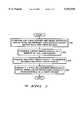
- FIG. 7shows a flow chart for a method of producing a pulsewidth modulated signal in accordance with a preferred embodiment of the present invention.
- the present inventionhelps solve the above-identified problems by providing an apparatus and method for reducing distortion in high efficiency linear power amplifiers.
- FIG. 1shows a diagram of an amplifier in accordance with a preferred embodiment of the present invention.
- Envelope Elimination and Restorationis a technique through which highly efficient but nonlinear radio frequency (RF) power amplifiers can be combined with other, highly efficient amplifiers to produce a high efficiency linear amplifier system.
- the signal to be amplifiedis split into two paths: an amplitude path, and a phase path.
- the detected envelopeis amplified efficiently in the amplitude path by a class S or other highly efficient power amplifier which operates on the bandwidth of the RF envelope rather than the RF bandwidth.
- the phase modulated carrier in the phase pathis then amplitude modulated by the amplified envelope signal, creating an amplified replica of the input signal.
- EER-type amplifier 10includes power divider 210, envelope detector 220, multi-output class S modulator 270, time delay element 230, limiter 240, driver amplifier 250, and power amplifier 260.
- EER-type amplifier 10receives an RF input into power divider 210.
- Power divider 210splits the RF input signal into an amplitude path which feeds envelope detector 220, and a phase path which feeds time delay element 230.
- the phase path of EER-type amplifier 10includes time delay element 230, limiter 240, driver amplifier 250, and power amplifier 260.
- Time delay element 230which produces a delay equal to that introduced by multi-output class S modulator 270 in the amplitude path, receives an output from power divider 210.
- Limiter 240receives the time delayed signal output from time delay element 230, and amplitude limits the signal. Limiter 240 can be omitted, or it can perform soft limiting, but limiter 240 preferably performs hard limiting so that the output of limiter 240 includes phase information with little or no amplitude information. After limiting, with the amplitude information removed, the resultant signal is the phase modulated carrier.
- phase modulated carrier output from limiter 240is then input to driver amplifier 250 which, in turn, drives power amplifier 260.
- Driver amplifier 250 and power amplifier 260are amplifier stages capable of being modulated, and are preferably field effect transistor (FET) amplifiers.
- FETfield effect transistor
- the drains of the FET amplifiersare conventionally connected to a DC power source; however, as will be discussed below, in a preferred embodiment exemplified herein, the drains of the FET amplifiers are driven with signals, resulting in an amplitude modulated output signal.
- time delay element 230is used in the phase path because it is desirable to recombine the signals from the amplitude path and the phase path after each has been subjected to substantially equal delays.
- the absolute delay of time delay element 230is such that the total delay in the phase path is substantially equal to the total delay in the amplitude path.
- Time delay element 230is shown as the first element in the phase path; however, the actual placement of time delay element 230 within the phase path is not a limitation of the present invention. Because the function of time delay element 230 is to balance the delays in the phase path and the amplitude path, the actual position of time delay element 230 in the phase path is not important.
- Alternate embodiments of the present inventionsubstantially match the delay in the two paths using circuit arrangements other than the one using time delay element 230 alone.
- multiple delay linesone in each of the phase path and amplitude path are used. In this case, the absolute delay of any one delay line assumes less importance, and the differential delay between the two delay lines is used to match the delays in the two paths.
- a differential delay linesuch as a surface acoustic wave (SAW) delay line, with one input and multiple outputs is used as a combination of power divider 210 and time delay element 230.
- SAWsurface acoustic wave
- the differential delayis used to match the delay in the two paths.
- the amplitude path of EER-type amplifier 10includes envelope detector 220 and multi-output class S modulator 270.
- Envelope detector 220detects the envelope of the RF input signal and outputs an envelope signal which represents the amplitude information included in the original RF input signal.
- Envelope detector 220is preferably a diode detector; however, other types of detectors, such as a synchronous detector based upon a double balanced mixer, could be used.
- Multi-output class S modulator 270amplifies the envelope signal (V E ) output from envelope detector 220 and drives the drain bias of power amplifier 260 with the amplified envelope signal (KV E ).
- Multi-output class S modulator 270amplifies the envelope signal to a level commensurate with the desired output.
- the output of multi-output class S modulator 270is the power supply for power amplifier 260, and the resultant remodulation of the phase modulated carrier restores the envelope, producing an amplified replica of the input signal.
- Multi-output class S modulator 270also outputs an offset amplified version of V E . This signal, (KV E +V 1 ), is used to modulate the driver amplifier.
- the EER-type amplifier of FIG. 1it is desirable to reduce phase distortion as much as possible, and in particular, it is desirable to reduce any phase distortion introduced by power amplifier 260.
- the present inventionprovides such a strategy for reducing the phase distortion in the power amplifier 260.
- EER-type amplifiersefficiency is gained by operating the final power amplifier at or near saturation.
- the amplifierWhen operating at or near saturation, the amplifier is operating at a region of compression, where as drive levels change, the phase of the output also changes.
- the input level to the final power amplifieris substantially constant while the amplifier is modulated by the envelope signal. Even though the amplifier is constantly at or near saturation, the compression point is changing as the drain bias is changed.
- a preferred embodiment of the present inventionprovides a strategy for reducing phase errors in power amplifier 260 which are a function of, among other things, changes in the compression point.
- power amplifier 260is operated at a substantially constant compression point thus reducing phase error contributions from the final power amplifier.
- driver amplifier 250By driving power amplifier 260 with driver amplifier 250, and by modulating driver amplifier 250 as a function of the amplified envelope, the relationship between the input to power amplifier 260 and the drain bias of power amplifier 260 are maintained such that power amplifier 260 is operated at a substantially constant compression point.
- the modulating signal for driver amplifier 250KV E +V 1 , causes the output of driver amplifier 250 to be distorted in response to the envelope of the original input signal.
- the distortion in driver amplifier 250 as a result of the modulating signalreduces the remaining distortion present in the driver amplifier chain.
- FIG. 2shows a diagram of a multi-output class S modulator in accordance with a preferred embodiment of the present invention.
- Multi-output class S modulator 270includes pulsewidth modulator 275, driver 280, switching transistors 285 and 287, low pass filter 290, and at least one isolated envelope tracking converter 700.
- Pulsewidth modulator (PWM) 275is a "primary" pulsewidth modulator because it receives the envelope signal (V E ) from envelope detector 220 (FIG. 1). PWM 275 outputs a pulsewidth modulated signal which has a duty cycle substantially proportional to the amplitude of the envelope signal.
- Driver 280accepts the pulsewidth modulated signal from PWM 275, and drives switching transistors 285 and 287 which alternately turn on as a function of the duty cycle of the pulsewidth modulated signal.
- Low pass filter 290filters the resulting amplified pulsewidth modulated signal, suppressing the switching frequency of PWM 270, and producing an amplified replica of the envelope signal.
- the amplified replica of the envelope signalis shown in FIG. 2 as KV E , where K represents the gain of the amplifier.
- KV Eis the primary amplified envelope signal because it is generated by primary PWM 270, and because it modulates the highest power amplifier in the phase path.
- Multi-output modulator 270also outputs offset versions of KV E . They are shown in FIG. 1 as KV E +V 1 , KV E +V 2 , and KV E +V N . Although the embodiment of multi-output amplifier 270 shown in FIG. 1 only uses two outputs (KV E and KV E +V 1 ), one skilled in the art will appreciate that any number of additional outputs could be generated using the method and apparatus of the present invention. Each offset output is generated by an isolated envelope tracking converter (IETC) 700.
- IETC 700includes "secondary" PWM 710, power transformer 720, rectifier 730, filter 740, error amplifier 750, and isolating coupler 760.
- error amplifier 750is referenced to the output of low pass filter 290, KV E .
- error amplifier 750is an operational amplifier with a "ground" of KV E .
- the inputs of error amplifier 750are the offset output, KV E +V 1 , and a reference voltage which is set to the desired offset, V 1 .
- the reference voltagecan be set to a value other than V 1 and power transformer 720 can step up or down an amount necessary to effect an offset equal to V 1 .
- the circuitis arranged such that the output of error amplifier 750 is an error term that will force the offset output, KV E +V 1 , to be substantially equal to the low pass filter output, KV E , plus the desired offset voltage of V 1 .
- the reference voltageis changed.
- FIG. 2shows two additional IETCs 700, one with the reference set to V2, and one with the reference set to V N , for producing the outputs KV E +V 1 and KV E +V N , respectively.
- error amplifier 750is input to PWM 710 after going through isolating coupler 760.
- the use of isolating coupler 760 to isolate error amplifier 750 from PWM 710allows error amplifier 750 to be referenced to KV E and PWM 710 to be referenced to a system ground.
- Isolating coupler 760can be one of many different types of coupling circuits including a magnetic coupler or an optical coupler.
- PWM 710receives the isolated error signal from isolating coupler 760 and generates a pulsewidth modulated signal.
- the pulsewidth modulated signal output from PWM 710has a duty cycle substantially proportional to the isolated error signal. This duty cycle is substantially constant, corresponding to the desirably constant reference voltage with variations due, in part, to corrections generated by the feedback.
- power transformer 720isolates the output of PWM 710 from the offset output.
- Power transformer 720isolates and steps up or steps down the voltage of the pulsewidth modulated signal. Because power transformer 720 can step up or down the PWM output, the resulting output offset can be more or less than the offset voltage present at the reference input to error amplifier 750. This allows standard reference diodes and other circuits to be used while generating offsets with various values.
- Rectifier 730 and filter 740then rectify and filter the isolated pulsewidth modulated signal to superimpose V 1 on top of KV E .
- Filter 740shown as a capacitor in FIG. 2, filters the rectified pulsewidth modulated signal and also functions to couple the KV E output with the offset, thereby generating the desired output, KV E +V 1 .
- Isolated envelope tracking converter 700provides advantages over prior art methods of generating offset voltages.
- One well known prior art methodis to use linear regulators. Linear regulators are dissipative and thus are inefficient.
- the embodiment of the present invention as shown in FIG. 2is much more efficient in part because it uses a switching pulsewidth modulator. Switching circuits are much more efficient than linear, dissipative circuits.
- FIG. 3shows an amplifier in accordance with an alternate embodiment of the present invention.
- an intermediate frequency (IF) signalis shown as the input signal to EER-type amplifier 20.
- the IF signalis input into power divider 210.
- Power divider 210functions to split the input signal into the amplitude path and the phase path.
- the amplitude pathfeeds envelope detector 220, and the phase path feeds time delay element 230.
- the amplitude path of EER-type amplifier 20includes envelope detector 220 and multi-output class S modulator 270. These elements correspond to the elements of FIG. 1 which have like names and like reference numbers.
- multi-output class S modulator 270corresponds to multi-output class S modulator 270 of FIG. 1, which was discussed in detail previously in connection with FIG. 2.
- the phase path of EER-type amplifier 20includes time delay element 230, limiter 240, frequency converter 245, driver amplifier 250, and power amplifier 260.
- Time delay element 230, limiter 240, driver amplifier 250, and power amplifier 260correspond to the elements shown in FIG. 1 with like names and like reference numbers.
- the alternate embodiment of FIG. 3includes frequency converter 245 in the phase path.
- Frequency converter 245receives the signal in the phase path and also receives a local oscillator (LO) signal.
- LOlocal oscillator
- Frequency converter 245converts the frequency of the carrier signal to its final RF frequency using circuits well known in the art, such as a mixer. The resulting signal is then used to drive driver amplifier 250, which in turn, drives power amplifier 260 which operates at the final RF frequency.
- FIG. 3shows an IF signal input to EER-type amplifier 20.
- the IF input signalcan be above or below the resultant RF frequency.
- a baseband signalcould also be used. Therefore, in the alternate embodiment exemplified in FIG. 3, the input signal can be at any frequency different from the RF frequency.
- frequency converter 245being an integral part of the amplifier
- the amplifierbecomes more tightly integrated with the device that houses the amplifier. Tighter integration results in smaller, lower power devices, which are easier to manufacture.
- FIG. 4shows a diagram of a communications device in accordance with a preferred embodiment of the present invention.
- Communications device 300includes amplifier 320 and antenna 310.
- Amplifier 320may comprise any of the amplifiers of the present invention, including for example, EER-type amplifier 10 (FIG. 1), multi-output class S modulator 270 (FIG. 2), or EER-type amplifier 20 (FIG. 3).
- Communications device 300may be one of many different devices capable of communications. Examples include, but are not limited to, subscriber units in a communications system, radio receivers, transmitters, and transceivers, one-way and two-way pagers, and cellular phones.
- FIGS. 5 and 6show a flow chart for a method of amplifying a signal in accordance with a preferred embodiment of the present invention.
- an input signalis split into an envelope signal in an amplitude path, and a carrier signal in a phase path.
- the signalis preferably split with a power divider where one output of the power divider feeds an envelope detector to create the envelope signal.
- Another output of the power splitteris fed to a limiter so that an amplitude limited phase modulated carrier exists in the phase path.
- a primary pulsewidth modulated signalis created.
- the primary pulsewidth modulated signalhas a duty cycle proportional to the envelope signal.
- the primary pulsewidth modulated signalis filtered to produce a primary amplified envelope signal.
- a first pulsewidth modulated signal(different from the primary pulsewidth modulated signal) is produced having a duty cycle substantially proportional to a first offset.
- step 525the first pulsewidth modulated signal is filtered and coupled with the primary amplified envelope signal resulting in a first offset amplified envelope signal.
- the primary amplified envelope signaland the first offset amplified envelope signal.
- the first offset amplified envelope signalhas been generated very efficiently by generating a pulsewidth modulated signal with a substantially constant duty cycle, filtering, and coupling with the result with the primary amplified envelope signal. Any number of additional offset envelope signals can be generated in a like manner, as is explained below with reference to FIG. 6.
- Step 545At least one additional pulsewidth modulated signal is generated with a duty cycle substantially proportional to an offset. If multiple additional pulsewidth modulated signals are generated, each is substantially proportional to a different offset, as one purpose of this step is create additional outputs, each with a different offset. Then, in step 550, each of the additional pulsewidth modulated signals generated in step 545 is filtered and coupled to the primary amplified envelope signal, thereby creating additional offset amplified envelope signals.
- step 535a final amplifier in the phase path is modulated with the primary amplified envelope signal.
- step 540a driver amplifier in the phase path is modulated with the first offset amplified envelope signal.
- the result of method 500is an amplified replica of the original input signal.
- the amplified replicais a high fidelity replica of the input signal because, in part, the driver amplifier has been modulated with the offset amplified envelope signal.
- method 500provides for efficient amplification because, in part, the first offset amplified envelope signal is generated with an efficient pulsewidth modulation technique. This technique is more fully explained with reference to FIG. 7.
- FIG. 7shows a flow chart for a method of producing a pulsewidth modulated signal in accordance with a preferred embodiment of the present invention.
- Method 520 as shown in FIG. 7corresponds to step 520 as shown in FIG. 5.
- step 610the first offset amplified envelope signal is compared with the primary amplified envelope signal plus an offset. This comparison step is the first step in a feedback loop that helps the desired offset output to be a high fidelity replica of the amplified envelope signal plus the desired offset.
- step 620an error signal is generated as a result of the comparison in step 610. Then, in step 630, the error signal is isolated resulting in an isolated error signal.
- the isolationis advantageous because, in part, it allows the comparison step and the steps that follow to be referenced to a different potential. For example, if the comparison step is performed by an operational amplifier, the operational amplifier can be referenced directly to the primary amplified envelope signal and the components that perform the steps following can be referenced to a system ground potential.
- step 630can be omitted if isolation between components is unnecessary.
- step 640the first pulsewidth modulated signal is created with a duty cycle substantially proportional to the isolated first error signal.
- the duty cycle of this pulsewidth modulated signalwill be substantially constant with variations due in part to the feedback comparison made in step 610.
- the method and apparatus of the present invention as describedrepresent a versatile way of achieving low phase distortion in a high efficiency, linear power amplifier.
- Highly efficient linear amplifiers with low phase distortionare very useful in the amplification of modulated signals which include information in both amplitude and phase.
- Communications deviceswhich often transmit signals having information in both amplitude and phase, benefit greatly from the apparatus and method of the present invention.
- Low distortionallows the communications devices to communicate more reliably, and high efficiency allows the devices to operate longer on a single battery.
- multiple driver amplifierscan be included, each having a modulating input. Then each modulating input can be driven by an additional offset amplified envelope output from the multi-output class S modulator.
Landscapes
- Engineering & Computer Science (AREA)
- Power Engineering (AREA)
- Amplifiers (AREA)
Abstract
Description
Claims (15)
Priority Applications (1)
| Application Number | Priority Date | Filing Date | Title |
|---|---|---|---|
| US08/998,749US5942938A (en) | 1997-12-29 | 1997-12-29 | Method and apparatus for high efficiency power amplification |
Applications Claiming Priority (1)
| Application Number | Priority Date | Filing Date | Title |
|---|---|---|---|
| US08/998,749US5942938A (en) | 1997-12-29 | 1997-12-29 | Method and apparatus for high efficiency power amplification |
Publications (1)
| Publication Number | Publication Date |
|---|---|
| US5942938Atrue US5942938A (en) | 1999-08-24 |
Family
ID=25545527
Family Applications (1)
| Application Number | Title | Priority Date | Filing Date |
|---|---|---|---|
| US08/998,749Expired - LifetimeUS5942938A (en) | 1997-12-29 | 1997-12-29 | Method and apparatus for high efficiency power amplification |
Country Status (1)
| Country | Link |
|---|---|
| US (1) | US5942938A (en) |
Cited By (24)
| Publication number | Priority date | Publication date | Assignee | Title |
|---|---|---|---|---|
| US6157253A (en)* | 1999-09-03 | 2000-12-05 | Motorola, Inc. | High efficiency power amplifier circuit with wide dynamic backoff range |
| US6252455B1 (en) | 1999-10-07 | 2001-06-26 | Motorola, Inc. | Method and apparatus for efficient signal amplification |
| US6366177B1 (en) | 2000-02-02 | 2002-04-02 | Tropian Inc. | High-efficiency power modulators |
| US6377784B2 (en) | 1999-02-09 | 2002-04-23 | Tropian, Inc. | High-efficiency modulation RF amplifier |
| US20030058956A1 (en)* | 2001-06-29 | 2003-03-27 | Seppo Rosnell | Switching mode power amplifier using PWM and PPM for bandpass signals |
| US6707857B1 (en) | 2000-07-14 | 2004-03-16 | Ericsson Inc. | Reference signal pre-distortion for transmitter with frequency synthesizer based phase encoding |
| US20040061555A1 (en)* | 2002-09-30 | 2004-04-01 | Lynch Michael Anthony | Controller for an RF power amplifier |
| WO2003056698A3 (en)* | 2001-12-24 | 2004-04-08 | Koninkl Philips Electronics Nv | Power amplifier |
| EP1410495A4 (en)* | 2001-03-21 | 2004-10-06 | Skyworks Solutions Inc | System for controlling a class d amplifier |
| US6839549B2 (en) | 2000-12-14 | 2005-01-04 | Ericsson Inc. | System and method of RF power amplification |
| US6864668B1 (en) | 1999-02-09 | 2005-03-08 | Tropian, Inc. | High-efficiency amplifier output level and burst control |
| WO2006021790A1 (en)* | 2004-08-25 | 2006-03-02 | Nujira Limited | High efficiency variable voltage supply |
| US20080024214A1 (en)* | 2006-07-27 | 2008-01-31 | Samsung Electronics Co., Ltd. | Power amplifier circuit for peak envelope modulation of high frequency signal |
| US20080061884A1 (en)* | 2006-09-08 | 2008-03-13 | Robert Michael Fisher | Amplifier feedback and bias configuration |
| US7471154B2 (en) | 2006-08-08 | 2008-12-30 | Skyworks Solutions, Inc. | Bias circuit for maintaining high linearity at cutback power conditions |
| EP1744449A4 (en)* | 2004-04-27 | 2009-03-18 | Panasonic Corp | AMPLIFIER, INFORMATION COMMUNICATION DEVICE, AND AMPLIFICATION METHOD |
| US20090115520A1 (en)* | 2006-12-04 | 2009-05-07 | Ripley David S | Temperature compensation of collector-voltage control RF amplifiers |
| US20090140804A1 (en)* | 2005-09-26 | 2009-06-04 | Paragon Communications Ltd. | Method and apparatus for improving the performance of mimo wireless systems |
| GB2459324A (en)* | 2008-04-18 | 2009-10-28 | Nujira Ltd | Multiple stage amplifier with modulated supply voltage |
| US20110090007A1 (en)* | 2008-04-18 | 2011-04-21 | Nujira Limited | Multi-stage amplifier |
| WO2011064306A1 (en)* | 2009-11-27 | 2011-06-03 | Nujira Limited | Parallel correction amplifier |
| US20120014694A1 (en)* | 2009-03-24 | 2012-01-19 | Wolfgang Templ | Method for data transmission using an envelope elimination and restoration amplifier, an envelope elimination and restoration amplifier, a transmitting device, a receiving device, and a communication network therefor |
| US20120313702A1 (en)* | 2011-06-09 | 2012-12-13 | Auriga Measurement Systems, LLC | Dual Rail Out-Phased Envelope Tracking Modulator |
| US8749308B2 (en) | 2003-02-19 | 2014-06-10 | Nujira Limited | High efficiency amplification |
Citations (6)
| Publication number | Priority date | Publication date | Assignee | Title |
|---|---|---|---|---|
| US3777275A (en)* | 1972-01-31 | 1973-12-04 | Bell Telephone Labor Inc | Linear amplification with nonlinear devices |
| US4831334A (en)* | 1987-06-08 | 1989-05-16 | Hughes Aircraft Company | Envelope amplifier |
| US5251330A (en)* | 1989-06-30 | 1993-10-05 | Nippon Telegraph & Telephone Corporation | Linear transmitter |
| US5831475A (en)* | 1997-08-04 | 1998-11-03 | Motorola, Inc. | Method and apparatus for delay matching in a power amplifier |
| US5847602A (en)* | 1997-03-03 | 1998-12-08 | Hewlett-Packard Company | Method and apparatus for linearizing an efficient class D/E power amplifier using delta modulation |
| US5861777A (en)* | 1997-07-02 | 1999-01-19 | Motorola, Inc. | Method and apparatus for compensation of phase distortion in power amplifiers |
- 1997
- 1997-12-29USUS08/998,749patent/US5942938A/ennot_activeExpired - Lifetime
Patent Citations (6)
| Publication number | Priority date | Publication date | Assignee | Title |
|---|---|---|---|---|
| US3777275A (en)* | 1972-01-31 | 1973-12-04 | Bell Telephone Labor Inc | Linear amplification with nonlinear devices |
| US4831334A (en)* | 1987-06-08 | 1989-05-16 | Hughes Aircraft Company | Envelope amplifier |
| US5251330A (en)* | 1989-06-30 | 1993-10-05 | Nippon Telegraph & Telephone Corporation | Linear transmitter |
| US5847602A (en)* | 1997-03-03 | 1998-12-08 | Hewlett-Packard Company | Method and apparatus for linearizing an efficient class D/E power amplifier using delta modulation |
| US5861777A (en)* | 1997-07-02 | 1999-01-19 | Motorola, Inc. | Method and apparatus for compensation of phase distortion in power amplifiers |
| US5831475A (en)* | 1997-08-04 | 1998-11-03 | Motorola, Inc. | Method and apparatus for delay matching in a power amplifier |
Cited By (48)
| Publication number | Priority date | Publication date | Assignee | Title |
|---|---|---|---|---|
| US6377784B2 (en) | 1999-02-09 | 2002-04-23 | Tropian, Inc. | High-efficiency modulation RF amplifier |
| US6864668B1 (en) | 1999-02-09 | 2005-03-08 | Tropian, Inc. | High-efficiency amplifier output level and burst control |
| US6157253A (en)* | 1999-09-03 | 2000-12-05 | Motorola, Inc. | High efficiency power amplifier circuit with wide dynamic backoff range |
| US6252455B1 (en) | 1999-10-07 | 2001-06-26 | Motorola, Inc. | Method and apparatus for efficient signal amplification |
| US6366177B1 (en) | 2000-02-02 | 2002-04-02 | Tropian Inc. | High-efficiency power modulators |
| US6707857B1 (en) | 2000-07-14 | 2004-03-16 | Ericsson Inc. | Reference signal pre-distortion for transmitter with frequency synthesizer based phase encoding |
| US6839549B2 (en) | 2000-12-14 | 2005-01-04 | Ericsson Inc. | System and method of RF power amplification |
| EP1410495A4 (en)* | 2001-03-21 | 2004-10-06 | Skyworks Solutions Inc | System for controlling a class d amplifier |
| CN100341241C (en)* | 2001-03-21 | 2007-10-03 | 斯盖沃克斯瑟路申斯公司 | system for controlling a class D amplifier |
| US6993087B2 (en)* | 2001-06-29 | 2006-01-31 | Nokia Mobile Phones Ltd. | Switching mode power amplifier using PWM and PPM for bandpass signals |
| US20030058956A1 (en)* | 2001-06-29 | 2003-03-27 | Seppo Rosnell | Switching mode power amplifier using PWM and PPM for bandpass signals |
| WO2003056698A3 (en)* | 2001-12-24 | 2004-04-08 | Koninkl Philips Electronics Nv | Power amplifier |
| US20040061555A1 (en)* | 2002-09-30 | 2004-04-01 | Lynch Michael Anthony | Controller for an RF power amplifier |
| US7091777B2 (en)* | 2002-09-30 | 2006-08-15 | Lucent Technologies Inc. | Controller for an RF power amplifier |
| US8749308B2 (en) | 2003-02-19 | 2014-06-10 | Nujira Limited | High efficiency amplification |
| US9118278B2 (en) | 2003-02-19 | 2015-08-25 | Snaptrack, Inc. | High efficiency amplification |
| US9190958B2 (en) | 2003-02-19 | 2015-11-17 | Snaptrack, Inc. | High efficiency amplification |
| US9641132B2 (en) | 2003-02-19 | 2017-05-02 | Snaptrack, Inc. | High efficiency amplification |
| EP1744449A4 (en)* | 2004-04-27 | 2009-03-18 | Panasonic Corp | AMPLIFIER, INFORMATION COMMUNICATION DEVICE, AND AMPLIFICATION METHOD |
| US20070210771A1 (en)* | 2004-08-25 | 2007-09-13 | Nujira Ltd. | High efficiency variable voltage supply |
| US9979353B2 (en) | 2004-08-25 | 2018-05-22 | Snaptrack, Inc. | High efficiency variable voltage supply |
| WO2006021790A1 (en)* | 2004-08-25 | 2006-03-02 | Nujira Limited | High efficiency variable voltage supply |
| US8680916B2 (en) | 2004-08-25 | 2014-03-25 | Nujira Limited | High efficiency variable voltage supply |
| US9379631B2 (en) | 2004-08-25 | 2016-06-28 | Snaptrack, Inc. | High efficiency variable voltage supply |
| US9608571B2 (en) | 2004-08-25 | 2017-03-28 | Snaptrack, Inc. | High efficiency variable voltage supply |
| US7782132B2 (en)* | 2005-09-26 | 2010-08-24 | Paragon Communications Ltd. | Method and apparatus for improving the performance of MIMO wireless systems |
| US20090140804A1 (en)* | 2005-09-26 | 2009-06-04 | Paragon Communications Ltd. | Method and apparatus for improving the performance of mimo wireless systems |
| US7554396B2 (en)* | 2006-07-27 | 2009-06-30 | Samsung Electronics Co., Ltd. | Power amplifier circuit for peak envelope modulation of high frequency signal |
| US20080024214A1 (en)* | 2006-07-27 | 2008-01-31 | Samsung Electronics Co., Ltd. | Power amplifier circuit for peak envelope modulation of high frequency signal |
| US7471154B2 (en) | 2006-08-08 | 2008-12-30 | Skyworks Solutions, Inc. | Bias circuit for maintaining high linearity at cutback power conditions |
| US20080061884A1 (en)* | 2006-09-08 | 2008-03-13 | Robert Michael Fisher | Amplifier feedback and bias configuration |
| US7446612B2 (en) | 2006-09-08 | 2008-11-04 | Skyworks Solutions, Inc. | Amplifier feedback and bias configuration |
| US7696826B2 (en) | 2006-12-04 | 2010-04-13 | Skyworks Solutions, Inc. | Temperature compensation of collector-voltage control RF amplifiers |
| US20090115520A1 (en)* | 2006-12-04 | 2009-05-07 | Ripley David S | Temperature compensation of collector-voltage control RF amplifiers |
| GB2459324A (en)* | 2008-04-18 | 2009-10-28 | Nujira Ltd | Multiple stage amplifier with modulated supply voltage |
| US20110090007A1 (en)* | 2008-04-18 | 2011-04-21 | Nujira Limited | Multi-stage amplifier |
| US8476976B2 (en) | 2008-04-18 | 2013-07-02 | Nujira Limited | Multi-stage amplifier |
| GB2459324B (en)* | 2008-04-18 | 2012-09-26 | Nujira Ltd | Multi-stage amplifier |
| US9337788B2 (en) | 2008-04-18 | 2016-05-10 | Snaptrack, Inc. | Multi-stage amplifier |
| US8611754B2 (en)* | 2009-03-24 | 2013-12-17 | Alcatel Lucent | Method for data transmission using an envelope elimination and restoration amplifier, an envelope elimination and restoration amplifier, a transmitting device, a receiving device, and a communication network therefor |
| US20120014694A1 (en)* | 2009-03-24 | 2012-01-19 | Wolfgang Templ | Method for data transmission using an envelope elimination and restoration amplifier, an envelope elimination and restoration amplifier, a transmitting device, a receiving device, and a communication network therefor |
| CN102812633B (en)* | 2009-11-27 | 2016-01-20 | 努吉拉有限公司 | parallel correction amplifier |
| US9209751B2 (en) | 2009-11-27 | 2015-12-08 | Snaptrack, Inc. | Parallel correction amplifier |
| US9379671B2 (en) | 2009-11-27 | 2016-06-28 | Snaptrack, Inc. | Parallel correction amplifier |
| CN102812633A (en)* | 2009-11-27 | 2012-12-05 | 努吉拉有限公司 | Parallel Correction Amplifier |
| WO2011064306A1 (en)* | 2009-11-27 | 2011-06-03 | Nujira Limited | Parallel correction amplifier |
| US20120313702A1 (en)* | 2011-06-09 | 2012-12-13 | Auriga Measurement Systems, LLC | Dual Rail Out-Phased Envelope Tracking Modulator |
| US8704594B2 (en)* | 2011-06-09 | 2014-04-22 | Auriga Measurement Systems, LLC | Dual rail out-phased envelope tracking modulator |
Similar Documents
| Publication | Publication Date | Title |
|---|---|---|
| US5942938A (en) | Method and apparatus for high efficiency power amplification | |
| US5886572A (en) | Method and apparatus for reducing distortion in a power amplifier | |
| US5936464A (en) | Method and apparatus for reducing distortion in a high efficiency power amplifier | |
| US6130910A (en) | Method and apparatus for high efficiency wideband power amplification | |
| US5861777A (en) | Method and apparatus for compensation of phase distortion in power amplifiers | |
| US6175273B1 (en) | Method and apparatus for high efficiency wideband power amplification | |
| US6252455B1 (en) | Method and apparatus for efficient signal amplification | |
| US6049707A (en) | Broadband multicarrier amplifier system and method using envelope elimination and restoration | |
| US5831475A (en) | Method and apparatus for delay matching in a power amplifier | |
| US5808512A (en) | Feed forward amplifiers and methods | |
| EP0863607B1 (en) | Method and apparatus for linearizing an efficient class D/E power amplifier using delta modulation | |
| US7696818B2 (en) | Amplifying apparatus | |
| AU759069B2 (en) | In-line, unbalanced amplifier, pre-distortion circuit | |
| US5239275A (en) | Amplitude modulator circuit having multiple power supplies | |
| US7728662B2 (en) | Saturated power amplifier with selectable and variable output power levels | |
| US20060264186A1 (en) | Transmitter | |
| GB2283628A (en) | Amplification of modulated signals | |
| US5990735A (en) | Method and apparatus for high efficiency power amplification | |
| US7620377B2 (en) | Bandwidth enhancement for envelope elimination and restoration transmission systems | |
| CA2228073A1 (en) | Linearization of an amplifier employing modified feedforward correction | |
| US7061313B2 (en) | Dual feedback linear amplifier | |
| US7164316B2 (en) | Series-Type Doherty Amplifier Without Hybrid Coupler | |
| US20090180530A1 (en) | Apparatus and method for amplifying signal power in a communication system | |
| JPH044614A (en) | Distortion correcting system for power amplifier | |
| KR20060052828A (en) | Amplification circuitry including envelope modulated limit period modulation circuitry |
Legal Events
| Date | Code | Title | Description |
|---|---|---|---|
| AS | Assignment | Owner name:MOTOROLA, INC., ILLINOIS Free format text:ASSIGNMENT OF ASSIGNORS INTEREST;ASSIGNORS:MEYERS, RONALD GENE;SIGMON, BERNARD EUGENE;JACKSON, ROBERT MICHAEL;REEL/FRAME:009219/0096;SIGNING DATES FROM 19980116 TO 19980120 | |
| STCF | Information on status: patent grant | Free format text:PATENTED CASE | |
| FPAY | Fee payment | Year of fee payment:4 | |
| FPAY | Fee payment | Year of fee payment:8 | |
| AS | Assignment | Owner name:MOTOROLA MOBILITY, INC, ILLINOIS Free format text:ASSIGNMENT OF ASSIGNORS INTEREST;ASSIGNOR:MOTOROLA, INC;REEL/FRAME:025673/0558 Effective date:20100731 | |
| FPAY | Fee payment | Year of fee payment:12 | |
| AS | Assignment | Owner name:MOTOROLA MOBILITY LLC, ILLINOIS Free format text:CHANGE OF NAME;ASSIGNOR:MOTOROLA MOBILITY, INC.;REEL/FRAME:029216/0282 Effective date:20120622 | |
| AS | Assignment | Owner name:GOOGLE TECHNOLOGY HOLDINGS LLC, CALIFORNIA Free format text:ASSIGNMENT OF ASSIGNORS INTEREST;ASSIGNOR:MOTOROLA MOBILITY LLC;REEL/FRAME:034475/0001 Effective date:20141028 |