US5942818A - Control apparatus for engine-driven permanent magnet type synchronous generators - Google Patents
Control apparatus for engine-driven permanent magnet type synchronous generatorsDownload PDFInfo
- Publication number
- US5942818A US5942818AUS09/020,297US2029798AUS5942818AUS 5942818 AUS5942818 AUS 5942818AUS 2029798 AUS2029798 AUS 2029798AUS 5942818 AUS5942818 AUS 5942818A
- Authority
- US
- United States
- Prior art keywords
- permanent magnet
- magnet type
- voltage
- circuit
- generator
- Prior art date
- Legal status (The legal status is an assumption and is not a legal conclusion. Google has not performed a legal analysis and makes no representation as to the accuracy of the status listed.)
- Expired - Lifetime
Links
Images


Classifications
- H—ELECTRICITY
- H02—GENERATION; CONVERSION OR DISTRIBUTION OF ELECTRIC POWER
- H02M—APPARATUS FOR CONVERSION BETWEEN AC AND AC, BETWEEN AC AND DC, OR BETWEEN DC AND DC, AND FOR USE WITH MAINS OR SIMILAR POWER SUPPLY SYSTEMS; CONVERSION OF DC OR AC INPUT POWER INTO SURGE OUTPUT POWER; CONTROL OR REGULATION THEREOF
- H02M5/00—Conversion of AC power input into AC power output, e.g. for change of voltage, for change of frequency, for change of number of phases
- H02M5/40—Conversion of AC power input into AC power output, e.g. for change of voltage, for change of frequency, for change of number of phases with intermediate conversion into DC
- H02M5/42—Conversion of AC power input into AC power output, e.g. for change of voltage, for change of frequency, for change of number of phases with intermediate conversion into DC by static converters
- H02M5/44—Conversion of AC power input into AC power output, e.g. for change of voltage, for change of frequency, for change of number of phases with intermediate conversion into DC by static converters using discharge tubes or semiconductor devices to convert the intermediate DC into AC
- H02M5/453—Conversion of AC power input into AC power output, e.g. for change of voltage, for change of frequency, for change of number of phases with intermediate conversion into DC by static converters using discharge tubes or semiconductor devices to convert the intermediate DC into AC using devices of a triode or transistor type requiring continuous application of a control signal
- H02M5/458—Conversion of AC power input into AC power output, e.g. for change of voltage, for change of frequency, for change of number of phases with intermediate conversion into DC by static converters using discharge tubes or semiconductor devices to convert the intermediate DC into AC using devices of a triode or transistor type requiring continuous application of a control signal using semiconductor devices only
- H—ELECTRICITY
- H02—GENERATION; CONVERSION OR DISTRIBUTION OF ELECTRIC POWER
- H02M—APPARATUS FOR CONVERSION BETWEEN AC AND AC, BETWEEN AC AND DC, OR BETWEEN DC AND DC, AND FOR USE WITH MAINS OR SIMILAR POWER SUPPLY SYSTEMS; CONVERSION OF DC OR AC INPUT POWER INTO SURGE OUTPUT POWER; CONTROL OR REGULATION THEREOF
- H02M7/00—Conversion of AC power input into DC power output; Conversion of DC power input into AC power output
- H02M7/02—Conversion of AC power input into DC power output without possibility of reversal
- H02M7/04—Conversion of AC power input into DC power output without possibility of reversal by static converters
- H02M7/12—Conversion of AC power input into DC power output without possibility of reversal by static converters using discharge tubes with control electrode or semiconductor devices with control electrode
- H02M7/21—Conversion of AC power input into DC power output without possibility of reversal by static converters using discharge tubes with control electrode or semiconductor devices with control electrode using devices of a triode or transistor type requiring continuous application of a control signal
- H02M7/217—Conversion of AC power input into DC power output without possibility of reversal by static converters using discharge tubes with control electrode or semiconductor devices with control electrode using devices of a triode or transistor type requiring continuous application of a control signal using semiconductor devices only
- H—ELECTRICITY
- H02—GENERATION; CONVERSION OR DISTRIBUTION OF ELECTRIC POWER
- H02P—CONTROL OR REGULATION OF ELECTRIC MOTORS, ELECTRIC GENERATORS OR DYNAMO-ELECTRIC CONVERTERS; CONTROLLING TRANSFORMERS, REACTORS OR CHOKE COILS
- H02P9/00—Arrangements for controlling electric generators for the purpose of obtaining a desired output
- H02P9/14—Arrangements for controlling electric generators for the purpose of obtaining a desired output by variation of field
- H02P9/26—Arrangements for controlling electric generators for the purpose of obtaining a desired output by variation of field using discharge tubes or semiconductor devices
- H02P9/30—Arrangements for controlling electric generators for the purpose of obtaining a desired output by variation of field using discharge tubes or semiconductor devices using semiconductor devices
- H02P9/305—Arrangements for controlling electric generators for the purpose of obtaining a desired output by variation of field using discharge tubes or semiconductor devices using semiconductor devices controlling voltage
- H02P9/307—Arrangements for controlling electric generators for the purpose of obtaining a desired output by variation of field using discharge tubes or semiconductor devices using semiconductor devices controlling voltage more than one voltage output
- H—ELECTRICITY
- H02—GENERATION; CONVERSION OR DISTRIBUTION OF ELECTRIC POWER
- H02M—APPARATUS FOR CONVERSION BETWEEN AC AND AC, BETWEEN AC AND DC, OR BETWEEN DC AND DC, AND FOR USE WITH MAINS OR SIMILAR POWER SUPPLY SYSTEMS; CONVERSION OF DC OR AC INPUT POWER INTO SURGE OUTPUT POWER; CONTROL OR REGULATION THEREOF
- H02M1/00—Details of apparatus for conversion
- H02M1/0067—Converter structures employing plural converter units, other than for parallel operation of the units on a single load
- H02M1/007—Plural converter units in cascade
- H—ELECTRICITY
- H02—GENERATION; CONVERSION OR DISTRIBUTION OF ELECTRIC POWER
- H02M—APPARATUS FOR CONVERSION BETWEEN AC AND AC, BETWEEN AC AND DC, OR BETWEEN DC AND DC, AND FOR USE WITH MAINS OR SIMILAR POWER SUPPLY SYSTEMS; CONVERSION OF DC OR AC INPUT POWER INTO SURGE OUTPUT POWER; CONTROL OR REGULATION THEREOF
- H02M3/00—Conversion of DC power input into DC power output
- H02M3/02—Conversion of DC power input into DC power output without intermediate conversion into AC
- H02M3/04—Conversion of DC power input into DC power output without intermediate conversion into AC by static converters
- H02M3/10—Conversion of DC power input into DC power output without intermediate conversion into AC by static converters using discharge tubes with control electrode or semiconductor devices with control electrode
- H02M3/145—Conversion of DC power input into DC power output without intermediate conversion into AC by static converters using discharge tubes with control electrode or semiconductor devices with control electrode using devices of a triode or transistor type requiring continuous application of a control signal
- H02M3/155—Conversion of DC power input into DC power output without intermediate conversion into AC by static converters using discharge tubes with control electrode or semiconductor devices with control electrode using devices of a triode or transistor type requiring continuous application of a control signal using semiconductor devices only
- H02M3/1552—Boost converters exploiting the leakage inductance of a transformer or of an alternator as boost inductor
- H—ELECTRICITY
- H02—GENERATION; CONVERSION OR DISTRIBUTION OF ELECTRIC POWER
- H02P—CONTROL OR REGULATION OF ELECTRIC MOTORS, ELECTRIC GENERATORS OR DYNAMO-ELECTRIC CONVERTERS; CONTROLLING TRANSFORMERS, REACTORS OR CHOKE COILS
- H02P2101/00—Special adaptation of control arrangements for generators
- H02P2101/45—Special adaptation of control arrangements for generators for motor vehicles, e.g. car alternators
Definitions
- This inventionrelates to a control apparatus for engine-driven permanent magnet type synchronous generators, adapted to control a voltage generated by a permanent magnet type synchronous generator driven by an automobile engine, and convert the DC power of a battery into commercial AC power.
- a generated voltagevaries in proportion to the rotational frequency of the engine which varies very widely from 500 rpm to several thousand rpm. Therefore, in order to use this generator as a commercial power source, a constant voltage control unit comprising a voltage step-up means and a voltage step-down means, and an inverter circuit for converting DC power into AC power of a desired frequency are required.
- the constant voltage control unitcomprises a voltage step-down circuit 2 and a voltage step-up circuit 3.
- the voltage step-down circuit 2is adapted to decrease a generated output voltage of a permanent magnet type generator 1, and comprises diodes D8, D9, D10 and thyristors S1, S2, S3, the gates of the thyristors S1, S2, S3 being controlled by a voltage step-down control circuit 4, whereby a voltage step-down control operation is carried out by reducing a conducting angle of a rectifying circuit.
- the voltage step-up circuit 3is adapted to increase a generated output voltage of the permanent magnet type generator 1, and comprises a leakage inductance of an armature coil 14 of the generator 1, diodes D8, D9, D10, D11, D12, D13, and switching transistors T8, T9, a voltage step-up control operation being carried out by controlling the switching transistors T8, T9 by a voltage step-up control circuit 5.
- the constant voltage control unit for the generator 1uses the thyristors S1-S3 and switching transistors T8, T9, and these elements are large current switching elements. Since a control circuit for controlling the large current switching elements are required, the price of the control unit becomes high, and a space necessary for installing these parts increases.
- the diodes D8, D9, D10, D11, D12, D13form a series circuit to cause a loss occurring in the elements to increase, and an efficiency to decrease.
- the switching transistor T8 connected in series to the voltage step-up control circuitalso constitutes a factor of the increase of the loss, and a switching operation of the switching transistor T9 is unstable in some cases, a special protective circuit being required for the switching transistor T8.
- Japanese Patent Laid-Open No. 237998/1996discloses a voltage control unit for a permanent magnet type three-phase AC generator, which is driven by an automobile engine without using a large current reactor, capable of obtaining a stable generated voltage of the generator at any rotational frequency of the engine.
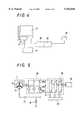
- a refrigerator-mounted truck by which materials, such as perishable foods held in a refrigerating or cold insulating container are transportedis provided with an electric power converter as shown in FIG. 7, which comprises a reactor or a transformer for converting the DC power (12V or 24V) of the automobile into AC power (100V or 200V), for operating the refrigerator (refer to, for example, Japanese Patent Laid-Open No. 285756/1989).
- a generator 1is driven by the engine 21 and generates power to charge a battery 16 with the step-up of a voltage of the battery 16 and the conversion of DC power into AC power controlled by a voltage step-up circuit 24 and an inverter circuit 25, whereby commercial AC power is supplied to a load, such as a compressor.
- a loadsuch as a compressor.
- the step-up of a voltage of the battery 16 and the conversion of DC power into AC powerare controlled by the voltage step-up circuit 24 and inverter circuit 25, and commercial DC power is supplied to the load 26.
- the electric power converter referred to abovewhich usually increases an output from a 12V or 24V generator 1 or a battery 16 to 100V or 200V by a voltage step-up circuit only, so that the voltage step-up circuit needs to comprise a voltage step-up reactor 27. Since the compressor for the refrigerator requires several KW power, the voltage step-up reactor 27 requires a current capacity of around 100 A. Consequently, the electric power converter has to comprise a large and heavy reactor.
- An object of the present inventionis to solve these problems, and provide a control apparatus for permanent magnet type generators, capable of obtaining a stable generated voltage of a permanent magnet type generator, which is driven by an automobile engine, at a rotational frequency in any range of the engine, using such a voltage as commercial power source voltage, i.e. AC voltage, and being formed to small dimensions at a low cost.
- a control apparatus for permanent magnet type generatorscapable of obtaining a stable generated voltage of a permanent magnet type generator, which is driven by an automobile engine, at a rotational frequency in any range of the engine, using such a voltage as commercial power source voltage, i.e. AC voltage, and being formed to small dimensions at a low cost.
- This inventionrelates to a control apparatus for permanent magnet type generators, comprising an engine-driven permanent magnet type generator, a voltage step-up and rectifying circuit for increasing a voltage of and rectifying electric power generated by the permanent magnet type generator, a smoothing capacitor parallel-connected to an output side of the voltage step-up and rectifying circuit, and a conversion circuit connected to an output side of the smoothing capacitor, adapted to convert an output from the voltage step-up and rectifying circuit into three-phase AC power by a pulse-width modulation control system and having a voltage step-down function.
- This control apparatus for permanent magnet type generatorscan be provided with an inductance series-connected to an output side of the conversion circuit.
- the voltage step-up and rectifying circuitcomprises a full-wave rectifier circuit formed of six diodes adapted to rectify a three-phase output from the permanent magnet type generator, switching elements parallel-connected to an output side of the full-wave rectifier circuit, diodes connected to positive output sides of the switching elements, a voltage detecting circuit for detecting a voltage outputted from the diodes, and a voltage step-up control circuit for controlling the switching elements.
- the conversion circuitcomprises a six-arm type inverter circuit connected to the output side of the smoothing capacitor, and an inverter control circuit for pulse-width modulation controlling the switching elements in the six-arm type inverter circuit.
- the enginecan be used as an engine to be mounted on an automobile in which the rotational frequency of the engine varies greatly.
- This control apparatus for permanent magnet type generatorsis formed as described above. Since the inverter circuit is formed so as to be pulse-width modulation controlled, it has become possible to provide the inverter circuit with an output voltage step-down function, reduce the number of the voltage step-down circuit elements for an output voltage from a permanent magnet type generator, and form the apparatus to small dimensions and weight and economically advantageously.
- this control apparatus for permanent magnet type generatorsis provided with a permanent magnet type generator driven by an engine, a battery for accumulating therein the electric power generated by the permanent magnet type generator, and a voltage step-up and step-down circuit adapted to supply the electric power, which is supplied from the permanent magnet type generator, to a load, and convert DC power, which is supplied from the battery, into commercial AC power and supply the AC power to the load, an output from the battery being applied to a neutral point of an armature coil of the permanent magnet type generator, whereby the electric power of the battery can be supplied as AC power.
- This control apparatus for permanent magnet type generatorshas an inductance between the battery and the neutral point of the armature coil of the generator.
- FIG. 1is a circuit diagram showing a first embodiment of the control apparatus for the voltage control unit-carrying permanent magnet type generator according to the present invention
- FIG. 2is an explanatory view showing an output waveform of the first embodiment
- FIG. 3is a circuit diagram showing a conventional voltage control unit
- FIG. 4is a general system diagram showing a second embodiment of the control apparatus for a power converter carrying permanent magnet type generator according to the present invention
- FIG. 5is a circuit diagram of the second embodiment of FIG. 4;
- FIG. 6is a circuit diagram showing a third embodiment of the control apparatus for a power converter-carrying permanent magnet type generator according to the present invention.
- FIG. 7is a general system diagram of a conventional power converter.
- FIG. 8is a circuit diagram of an inverter for the conventional power converter.
- the control apparatus for permanent magnet type generators of the first embodimenthas a voltage control unit, which is adapted to control a voltage of a permanent magnet type generator 1, which is driven by an engine mounted on an automobile, in such a manner that this voltage can be used as commercial source power 11, and enables the number of a large current switching elements T1 to be reduced to one, and the apparatus to be formed to small dimensions and weight and economically advantageously.
- the voltage control unit in the first embodimentis adapted to control an output from the engine-driven permanent magnet type generator 1, and supply the commercial source power 11, and comprises a voltage step-up and rectifying circuit 12 for increasing the voltage of and rectifying the power generated by the generator 1, a smoothing capacitor C parallel-connected to an output side of the voltage step-up and rectifying circuit 12, a conversion circuit 13 connected to an output side of the capacitor C, adapted to convert an output from the voltage step-up and rectifying circuit 12 into three-phase AC power by a pulse-width modulation control system, and having a voltage step-down function, and an inductance L series-connected to an output side of the conversion circuit 13.
- providing the inductance L or not providing the sameis dependent upon a machine (load 11) connected to an output side thereof, and providing the inductance L is not an absolute condition.
- the generator 1comprises a rotor formed of a permanent magnet, and a stator formed of armature coils 14, i.e. an armature, and is adapted to generate a three-phase output.
- a DC power source 16, such as a batteryis connected to a neutral point 15 of the armature coil 14 through a switch 17.
- the voltage step-up and rectifying circuit 12is adapted to increase a three-phase output of electric power generated by the generator 1 and rectify the resultant output, and comprises a three-phase full-wave rectifier circuit 8 formed of six diodes D1, D2, D3, D4, D5, D6, a power transistor T1 parallel-connected to an output side of the full-wave rectifier circuit 8 and forming a switching element for carrying out a voltage step-up chopping operation, a diode D7 connected to a collector-output side of the power transistor T1, a voltage detecting circuit 10 for detecting a voltage outputted from the diode D7, and a voltage step-up control circuit 9 for controlling the power transistor T1.
- the voltage step-up control circuit 9is adapted to increase a generated voltage of the generator 1 when the generated voltage at the output side (shown by a point A in the circuit) after a DC conversion operation does not reach a target level, the transistor T1 being turned on and off for this purpose.
- the voltage step-up control circuit 9functions concretely as follows.
- the energy accumulated in the armature coil 14turns into a counter-electromotive force, which is added to a regular generated voltage from the generator 1, so that a DC voltage higher than the voltage occurring when a regular generated voltage is rectified is obtained.
- the conversion circuit 13comprises an inverter circuit 6 formed of transistors T2, T3, T4, T5, T6, T7, and an inverter circuit 7 for carrying out a pulse-width modulation control operation, and is connected to an output side of the smoothing capacitor C.
- the conversion circuit 13is adapted to convert an output from the voltage step-up and rectifying circuit 12 into three-phase AC current by a pulse-width modulation control system, and has a voltage step-down function.
- the inverter circuit 6is adapted to convert an output from the voltage step-up and rectifying circuit into a three-phase AC power of a desired frequency.
- An inductance Lis series-connected to an output side of the conversion circuit 13, and an output from the conversion circuit 13 is supplied to a load 11, which consumes commercial source power, through the inductance L. During this time, the inductance L connected to an output portion of the inverter circuit 6 forms an output power smoothing reactor.
- the inverter circuit 6is controlled by the inverter control circuit 7 of a pulse-width modulation system.
- a leading edge, a trailing edge or both thereofare changed, whereby a pulse having a width proportional to a momentary value of a modulation signal is formed, by which pulse a voltage step-down control operation is carried out.
- the conversion circuit 13changes an ON-OFF time ratio of a pulse carrier wave (carrier pulse) as shown in FIG. 2b, and lowers an effective voltage.
- the ON time and OFF time of the pulseare determined in accordance with a difference between the voltage at the point A and a target voltage so that the three-phase AC voltage becomes constant.
- the pulse-width modulationis not carried out as shown in FIG. 2a when the voltage at the point A is not higher than the target voltage.
- FIGS. 2a and 2bexamples of rectangular waveforms of outputs from the inverter circuit 6 are shown. Even when an output from the inverter has a sine wave-like waveform shown in FIG. 2c, it can be controlled in the same manner.
- a DC power source 16such as a battery is connected to the neutral point 15 of the armature coil 14 through a power source driving switch 17.
- This switch 17is controlled so that it is connected when the load 11 on commercial source power is turned on during the stoppage of the engine.
- the power source driving switch 17When the power source driving switch 17 is turned on, a current from the DC power source 16 is supplied to the voltage step-up control circuit 9 through the armature coil 14 of the generator 1.
- the voltage of the DC power source 16such as a battery is 12V-24V, and requires to be increased. Therefore, the transistor T1 forming a switching element is switched at several KHz--several tens of KHz by the voltage step-up control circuit 9. Consequently, the accumulation and discharge of energy occur repeatedly in a leakage inductance portion of the armature coil 14 of the generator 1 to cause a chopper action, whereby the electric power the voltage of which is increased higher than that of the battery is supplied to the capacitor C through the diodes D1, D2, D3, D7. Accordingly, the electric power from the DC power source of a battery can be supplied to the load 11 consuming commercial source power.
- FIGS. 4, 5 and 6Some other embodiments of the control apparatus for permanent magnet type generators according to the present invention will now be described with reference to FIGS. 4, 5 and 6. These embodiments are provided with a power conversion unit, and can use an inductance portion of an armature coil 14 of a generator 1 also as a reactor of a voltage step-up and step-down circuit 28a, 28b, 2bc i.e., a voltage step-up and step-down circuit 28a, 28b, 2bc without requiring an independent reactor of a voltage step-up control circuit can be formed.
- a voltage step-up and step-down circuit 28a, 28b, 2bci.e., a voltage step-up and step-down circuit 28a, 28b, 2bc without requiring an independent reactor of a voltage step-up control circuit can be formed.
- FIGS. 4 and 5a second embodiment of the control apparatus for permanent magnet type generators having a power conversion unit will now be described with reference to FIGS. 4 and 5.
- the parts thereof identical with those of the prior art example of FIG. 7are designated by the same reference numbers.
- an engine 21is provided with a permanent magnet type generator 1 driven via a belt which transmits a driving power of the engine 21 thereto.
- An output from the generator 1is subjected to a voltage step-up or step-down operation suitably in the voltage step-up and step-down circuit 28 and thereby regulated to a constant level, the resultant voltage being applied to an inverter circuit 25.
- the inverter circuit 25is adapted to convert the DC power of the voltage step-up and step-down circuit 28 into commercial AC power necessary for the load 26.
- a battery 16is connected to a neutral point 15 of the armature coil 14 of the generator 1 through a driving switch 17 for the battery 16.
- the driving switch 17 for the battery 16is controlled so that it is closed when a load 26 using commercial AC power is turned on during the stoppage of the operation of the engine 21.
- the generator 1is a three-phase synchronous generator provided with the star-connected armature coil 14 having the neutral point 15 with a rotor comprising a permanent magnet. Various phases of outputs from the generator 1 are sent out to the voltage step-up control circuit 28.
- the voltage step-up and step-down circuit 28comprises a switching element 28a, a thyristor 28b and a diode 28c for every phase of the generator 1. Although the voltage step-up and step-down circuit 28 does not have a reactor, it utilizes a leakage inductance portion of the armature coil 14 of the generator 1 as a reactor.
- the controlling of the step-up and step-down of a voltageis done by controlling the switching element 28a and thyristor 28b in a known control circuit.
- the switching element 28awhen an actual voltage is higher than a target level, the switching element 28a is turned off, and the thyristor 28b is subjected to a phase angle control operation to decrease the voltage.
- the thyristor 28bWhen the actual voltage is lower than a target level, the thyristor 28b is turned on, and the switching element 28a is switched at several KHz--several tens of KHz, whereby the voltage is increased by a leakage inductance portion of the armature coil 14.
- the inverter circuit 25a best suitable circuit is selected according to the load 26.
- the control circuit in this embodimentis the inverter circuit 25 comprising a known three-phase output control circuit 23 as shown in FIG. 5.
- the battery 16is connected to the neutral point 15 of the armature coil 14 of the generator 1 through a positive terminal of the battery and the driving switch 17.
- the driving switch 17 for the battery 16is closed. Consequently, an electric current is supplied from the battery 16 to the voltage step-up and step-down circuit 28 through the armature coil 14 of the generator 1.
- the voltage from the battery 16is 12V or 24V and requires to be increased, so that the switching element 28a is switched at several KHz--several tens of KHz by turning on the thyristor 28b of the voltage step-up and step-down circuit 28, whereby the voltage is increased by the leakage inductance portion of the armature coil 14 of the generator 1.
- a third embodiment of the control apparatus for permanent magnet type generators having a power conversion unit according to the present inventionwill now be described with reference to FIG. 6.
- the parts thereof identical with those shown in FIG. 5are designated by the same reference numerals, and the duplication of descriptions is omitted.
- the third embodimentdiffers from the second embodiment in that an inductance 22 is inserted between a driving switch 17 for the battery 16 and a neutral point 15 of a generator 1 in the former.
- the inductance 22is capable of compensating for a deficiency of a leakage inductance portion of an armature coil 14 of a generator 1 when the leakage inductance portion is small with respect to the electric power which a load 26 requires, with a sufficient increase in the voltage not obtained.
- the inductance 22enables required power to be supplied, and the voltage to be sufficiently increased.
Landscapes
- Engineering & Computer Science (AREA)
- Power Engineering (AREA)
- Control Of Eletrric Generators (AREA)
Abstract
Description
1. FIELD OF THE INVENTION
This invention relates to a control apparatus for engine-driven permanent magnet type synchronous generators, adapted to control a voltage generated by a permanent magnet type synchronous generator driven by an automobile engine, and convert the DC power of a battery into commercial AC power.
2. DESCRIPTION OF THE PRIOR ART
In an AC generator driven by an automobile engine, a generated voltage varies in proportion to the rotational frequency of the engine which varies very widely from 500 rpm to several thousand rpm. Therefore, in order to use this generator as a commercial power source, a constant voltage control unit comprising a voltage step-up means and a voltage step-down means, and an inverter circuit for converting DC power into AC power of a desired frequency are required.
An example of a conventional constant voltage control unit is shown in FIG. 3. As shown in FIG. 3, the constant voltage control unit comprises a voltage step-down circuit 2 and a voltage step-up circuit 3. The voltage step-down circuit 2 is adapted to decrease a generated output voltage of a permanentmagnet type generator 1, and comprises diodes D8, D9, D10 and thyristors S1, S2, S3, the gates of the thyristors S1, S2, S3 being controlled by a voltage step-down control circuit 4, whereby a voltage step-down control operation is carried out by reducing a conducting angle of a rectifying circuit.
The voltage step-up circuit 3 is adapted to increase a generated output voltage of the permanentmagnet type generator 1, and comprises a leakage inductance of anarmature coil 14 of thegenerator 1, diodes D8, D9, D10, D11, D12, D13, and switching transistors T8, T9, a voltage step-up control operation being carried out by controlling the switching transistors T8, T9 by a voltage step-up control circuit 5.
The constant voltage control unit for thegenerator 1 uses the thyristors S1-S3 and switching transistors T8, T9, and these elements are large current switching elements. Since a control circuit for controlling the large current switching elements are required, the price of the control unit becomes high, and a space necessary for installing these parts increases. During an operation of the voltage step-up control circuit, the diodes D8, D9, D10, D11, D12, D13 form a series circuit to cause a loss occurring in the elements to increase, and an efficiency to decrease. The switching transistor T8 connected in series to the voltage step-up control circuit also constitutes a factor of the increase of the loss, and a switching operation of the switching transistor T9 is unstable in some cases, a special protective circuit being required for the switching transistor T8.
Japanese Patent Laid-Open No. 237998/1996 discloses a voltage control unit for a permanent magnet type three-phase AC generator, which is driven by an automobile engine without using a large current reactor, capable of obtaining a stable generated voltage of the generator at any rotational frequency of the engine.
A refrigerator-mounted truck by which materials, such as perishable foods held in a refrigerating or cold insulating container are transported is provided with an electric power converter as shown in FIG. 7, which comprises a reactor or a transformer for converting the DC power (12V or 24V) of the automobile into AC power (100V or 200V), for operating the refrigerator (refer to, for example, Japanese Patent Laid-Open No. 285756/1989).
As shown in FIG. 7, when anengine 21 is operated with the vehicle traveling, agenerator 1 is driven by theengine 21 and generates power to charge abattery 16 with the step-up of a voltage of thebattery 16 and the conversion of DC power into AC power controlled by a voltage step-upcircuit 24 and aninverter circuit 25, whereby commercial AC power is supplied to a load, such as a compressor. When theengine 21 is stopped, the step-up of a voltage of thebattery 16 and the conversion of DC power into AC power are controlled by the voltage step-upcircuit 24 andinverter circuit 25, and commercial DC power is supplied to theload 26.
As shown in FIG. 8, the electric power converter referred to above, which usually increases an output from a 12V or24V generator 1 or abattery 16 to 100V or 200V by a voltage step-up circuit only, so that the voltage step-up circuit needs to comprise a voltage step-upreactor 27. Since the compressor for the refrigerator requires several KW power, the voltage step-upreactor 27 requires a current capacity of around 100 A. Consequently, the electric power converter has to comprise a large and heavy reactor.
An object of the present invention is to solve these problems, and provide a control apparatus for permanent magnet type generators, capable of obtaining a stable generated voltage of a permanent magnet type generator, which is driven by an automobile engine, at a rotational frequency in any range of the engine, using such a voltage as commercial power source voltage, i.e. AC voltage, and being formed to small dimensions at a low cost.
This invention relates to a control apparatus for permanent magnet type generators, comprising an engine-driven permanent magnet type generator, a voltage step-up and rectifying circuit for increasing a voltage of and rectifying electric power generated by the permanent magnet type generator, a smoothing capacitor parallel-connected to an output side of the voltage step-up and rectifying circuit, and a conversion circuit connected to an output side of the smoothing capacitor, adapted to convert an output from the voltage step-up and rectifying circuit into three-phase AC power by a pulse-width modulation control system and having a voltage step-down function.
This control apparatus for permanent magnet type generators can be provided with an inductance series-connected to an output side of the conversion circuit.
The voltage step-up and rectifying circuit comprises a full-wave rectifier circuit formed of six diodes adapted to rectify a three-phase output from the permanent magnet type generator, switching elements parallel-connected to an output side of the full-wave rectifier circuit, diodes connected to positive output sides of the switching elements, a voltage detecting circuit for detecting a voltage outputted from the diodes, and a voltage step-up control circuit for controlling the switching elements.
The conversion circuit comprises a six-arm type inverter circuit connected to the output side of the smoothing capacitor, and an inverter control circuit for pulse-width modulation controlling the switching elements in the six-arm type inverter circuit.
In this control apparatus for permanent magnet type generators, the engine can be used as an engine to be mounted on an automobile in which the rotational frequency of the engine varies greatly.
This control apparatus for permanent magnet type generators is formed as described above. Since the inverter circuit is formed so as to be pulse-width modulation controlled, it has become possible to provide the inverter circuit with an output voltage step-down function, reduce the number of the voltage step-down circuit elements for an output voltage from a permanent magnet type generator, and form the apparatus to small dimensions and weight and economically advantageously.
In this control apparatus for permanent magnet type generators, stable commercial AC power can be obtained even when the engine is stopped, by applying an output from a DC power source, such as a battery to a neutral point of an armature coil constituting the permanent magnet generator.
Namely, this control apparatus for permanent magnet type generators is provided with a permanent magnet type generator driven by an engine, a battery for accumulating therein the electric power generated by the permanent magnet type generator, and a voltage step-up and step-down circuit adapted to supply the electric power, which is supplied from the permanent magnet type generator, to a load, and convert DC power, which is supplied from the battery, into commercial AC power and supply the AC power to the load, an output from the battery being applied to a neutral point of an armature coil of the permanent magnet type generator, whereby the electric power of the battery can be supplied as AC power.
This control apparatus for permanent magnet type generators has an inductance between the battery and the neutral point of the armature coil of the generator.
When it is necessary that electric power be applied to a load during the stoppage of the engine, in this control apparatus of the above-described structure for permanent magnet type generators, electric power is supplied from the battery to the neutral point of the armature coil of a generator being controlled, to increase the voltage. Therefore, the inductance portion of the armature coil of the generator can also be used as a reactor of the voltage step-up circuit. This enables commercial AC power to be supplied without using an independent reactor in a voltage step-up circuit, the number of parts to be reduced, and a space to be saved.
FIG. 1 is a circuit diagram showing a first embodiment of the control apparatus for the voltage control unit-carrying permanent magnet type generator according to the present invention;
FIG. 2 is an explanatory view showing an output waveform of the first embodiment;
FIG. 3 is a circuit diagram showing a conventional voltage control unit;
FIG. 4 is a general system diagram showing a second embodiment of the control apparatus for a power converter carrying permanent magnet type generator according to the present invention;
FIG. 5 is a circuit diagram of the second embodiment of FIG. 4;
FIG. 6 is a circuit diagram showing a third embodiment of the control apparatus for a power converter-carrying permanent magnet type generator according to the present invention;
FIG. 7 is a general system diagram of a conventional power converter; and
FIG. 8 is a circuit diagram of an inverter for the conventional power converter.
The embodiments of the control apparatus for permanent magnet type generators according to the present invention will now be described with reference to the drawings.
A first embodiment of the control apparatus for permanent magnet type generators according to the present invention will now be described with reference to FIG. 1. The control apparatus for permanent magnet type generators of the first embodiment has a voltage control unit, which is adapted to control a voltage of a permanentmagnet type generator 1, which is driven by an engine mounted on an automobile, in such a manner that this voltage can be used ascommercial source power 11, and enables the number of a large current switching elements T1 to be reduced to one, and the apparatus to be formed to small dimensions and weight and economically advantageously.
As shown in FIG. 1, the voltage control unit in the first embodiment is adapted to control an output from the engine-driven permanentmagnet type generator 1, and supply thecommercial source power 11, and comprises a voltage step-up and rectifyingcircuit 12 for increasing the voltage of and rectifying the power generated by thegenerator 1, a smoothing capacitor C parallel-connected to an output side of the voltage step-up and rectifyingcircuit 12, aconversion circuit 13 connected to an output side of the capacitor C, adapted to convert an output from the voltage step-up and rectifyingcircuit 12 into three-phase AC power by a pulse-width modulation control system, and having a voltage step-down function, and an inductance L series-connected to an output side of theconversion circuit 13. In the voltage control unit, providing the inductance L or not providing the same is dependent upon a machine (load 11) connected to an output side thereof, and providing the inductance L is not an absolute condition.
Thegenerator 1 comprises a rotor formed of a permanent magnet, and a stator formed ofarmature coils 14, i.e. an armature, and is adapted to generate a three-phase output. ADC power source 16, such as a battery is connected to aneutral point 15 of thearmature coil 14 through aswitch 17.
The voltage step-up and rectifyingcircuit 12 is adapted to increase a three-phase output of electric power generated by thegenerator 1 and rectify the resultant output, and comprises a three-phase full-wave rectifier circuit 8 formed of six diodes D1, D2, D3, D4, D5, D6, a power transistor T1 parallel-connected to an output side of the full-wave rectifier circuit 8 and forming a switching element for carrying out a voltage step-up chopping operation, a diode D7 connected to a collector-output side of the power transistor T1, avoltage detecting circuit 10 for detecting a voltage outputted from the diode D7, and a voltage step-up control circuit 9 for controlling the power transistor T1.
The voltage step-up control circuit 9 is adapted to increase a generated voltage of thegenerator 1 when the generated voltage at the output side (shown by a point A in the circuit) after a DC conversion operation does not reach a target level, the transistor T1 being turned on and off for this purpose.
When the transistor T1 is turned on, an output from thegenerator 1 is short-circuited, and a short-circuit current flows to thearmature coil 14 of thegenerator 1, so that the energy is accumulated in the leakage inductance of thearmature coil 14. When the transistor T1 is then turned off, the accumulated energy is released, so that an output voltage increases. When the voltage at the point A is not lower than the target level, the ON-OFF operations of the transistor T1 is stopped. Thus, an output from thegenerator 1 is subjected to a voltage step-up operation or kept as it is, and then rectified into a direct current in the three-phase full-wave rectifier circuit 8, the resultant current being sent to the inverter circuit 6 in theconversion circuit 13.
The voltage step-up control circuit 9 functions concretely as follows.
When a voltage between lines U, V of thegenerator 1 has a positive half cycle in the voltage step-up control circuit 9, a base switching signal of the transistor T1 is transmitted in a rectifier circuit in which a current flows from the diode D1 to the diode D5 through the transistor T1. The transistor T1 receives this signal and is turned on, so that an output from thegenerator 1 is short-circuited. Consequently, a short-circuit current flows through thearmature coil 14 of thegenerator 1, in which large energy is accumulated since thearmature coil 14 has a function of an inductance. When an OFF signal is then transmitted to the transistor T1, it is turned off, and the energy accumulated in thearmature coil 14 is sent out through the diode D7. During this time, the energy accumulated in thearmature coil 14 turns into a counter-electromotive force, which is added to a regular generated voltage from thegenerator 1, so that a DC voltage higher than the voltage occurring when a regular generated voltage is rectified is obtained.
When a voltage between the lines U, V of thegenerator 1 has a negative half cycle in the voltage step-up control circuit 9, a base switching signal of the transistor T1 is sent out similarly in a rectifier circuit in which a current flows from the diode D2 to the diode D4 through the transistor T1. The transistor T1 receives this signal and is turned on, so that an output from thegenerator 1 is short-circuited. Consequently, a short-circuit current flows in thearmature coil 14 of thegenerator 1, and large energy is accumulated in thearmature coil 14 since thearmature coil 14 has a function of an inductance. When an OFF signal is outputted to the transistor T1, it is operated in the same manner as mentioned above.
Theconversion circuit 13 comprises an inverter circuit 6 formed of transistors T2, T3, T4, T5, T6, T7, and an inverter circuit 7 for carrying out a pulse-width modulation control operation, and is connected to an output side of the smoothing capacitor C. Theconversion circuit 13 is adapted to convert an output from the voltage step-up and rectifyingcircuit 12 into three-phase AC current by a pulse-width modulation control system, and has a voltage step-down function. Namely, the inverter circuit 6 is adapted to convert an output from the voltage step-up and rectifying circuit into a three-phase AC power of a desired frequency. An inductance L is series-connected to an output side of theconversion circuit 13, and an output from theconversion circuit 13 is supplied to aload 11, which consumes commercial source power, through the inductance L. During this time, the inductance L connected to an output portion of the inverter circuit 6 forms an output power smoothing reactor.
The inverter circuit 6 is controlled by the inverter control circuit 7 of a pulse-width modulation system. In the pulse-width modulation control system, a leading edge, a trailing edge or both thereof are changed, whereby a pulse having a width proportional to a momentary value of a modulation signal is formed, by which pulse a voltage step-down control operation is carried out.
When a voltage at the point A is not lower than a target level, theconversion circuit 13 changes an ON-OFF time ratio of a pulse carrier wave (carrier pulse) as shown in FIG. 2b, and lowers an effective voltage. The ON time and OFF time of the pulse are determined in accordance with a difference between the voltage at the point A and a target voltage so that the three-phase AC voltage becomes constant. In theconversion circuit 13, the pulse-width modulation is not carried out as shown in FIG. 2a when the voltage at the point A is not higher than the target voltage.
In the above-described embodiment, an example of three-phase circuit is shown, and the embodiment can also be formed similarly even when a single-phase inverter is used. In FIGS. 2a and 2b, examples of rectangular waveforms of outputs from the inverter circuit 6 are shown. Even when an output from the inverter has a sine wave-like waveform shown in FIG. 2c, it can be controlled in the same manner.
In the voltage control unit for this control apparatus for permanent magnet type generators, aDC power source 16, such as a battery is connected to theneutral point 15 of thearmature coil 14 through a powersource driving switch 17. Thisswitch 17 is controlled so that it is connected when theload 11 on commercial source power is turned on during the stoppage of the engine.
When the powersource driving switch 17 is turned on, a current from theDC power source 16 is supplied to the voltage step-up control circuit 9 through thearmature coil 14 of thegenerator 1. The voltage of theDC power source 16, such as a battery is 12V-24V, and requires to be increased. Therefore, the transistor T1 forming a switching element is switched at several KHz--several tens of KHz by the voltage step-up control circuit 9. Consequently, the accumulation and discharge of energy occur repeatedly in a leakage inductance portion of thearmature coil 14 of thegenerator 1 to cause a chopper action, whereby the electric power the voltage of which is increased higher than that of the battery is supplied to the capacitor C through the diodes D1, D2, D3, D7. Accordingly, the electric power from the DC power source of a battery can be supplied to theload 11 consuming commercial source power.
Some other embodiments of the control apparatus for permanent magnet type generators according to the present invention will now be described with reference to FIGS. 4, 5 and 6. These embodiments are provided with a power conversion unit, and can use an inductance portion of anarmature coil 14 of agenerator 1 also as a reactor of a voltage step-up and step-downcircuit circuit
First, a second embodiment of the control apparatus for permanent magnet type generators having a power conversion unit will now be described with reference to FIGS. 4 and 5. In the second embodiment of FIGS. 4 and 5, the parts thereof identical with those of the prior art example of FIG. 7 are designated by the same reference numbers.
As shown in FIG. 4, anengine 21 is provided with a permanentmagnet type generator 1 driven via a belt which transmits a driving power of theengine 21 thereto. An output from thegenerator 1 is subjected to a voltage step-up or step-down operation suitably in the voltage step-up and step-down circuit 28 and thereby regulated to a constant level, the resultant voltage being applied to aninverter circuit 25. Theinverter circuit 25 is adapted to convert the DC power of the voltage step-up and step-down circuit 28 into commercial AC power necessary for theload 26.
Abattery 16 is connected to aneutral point 15 of thearmature coil 14 of thegenerator 1 through a drivingswitch 17 for thebattery 16. The drivingswitch 17 for thebattery 16 is controlled so that it is closed when aload 26 using commercial AC power is turned on during the stoppage of the operation of theengine 21.
The operation of the second embodiment of FIG. 4 will now be described with reference to FIG. 5. Thegenerator 1 is a three-phase synchronous generator provided with the star-connectedarmature coil 14 having theneutral point 15 with a rotor comprising a permanent magnet. Various phases of outputs from thegenerator 1 are sent out to the voltage step-upcontrol circuit 28.
The voltage step-up and step-down circuit 28 comprises aswitching element 28a, athyristor 28b and adiode 28c for every phase of thegenerator 1. Although the voltage step-up and step-down circuit 28 does not have a reactor, it utilizes a leakage inductance portion of thearmature coil 14 of thegenerator 1 as a reactor. The controlling of the step-up and step-down of a voltage is done by controlling theswitching element 28a andthyristor 28b in a known control circuit.
Namely, when an actual voltage is higher than a target level, the switchingelement 28a is turned off, and thethyristor 28b is subjected to a phase angle control operation to decrease the voltage. When the actual voltage is lower than a target level, thethyristor 28b is turned on, and theswitching element 28a is switched at several KHz--several tens of KHz, whereby the voltage is increased by a leakage inductance portion of thearmature coil 14.
In theinverter circuit 25, a best suitable circuit is selected according to theload 26. In the second embodiment, an example in which a three-phase motor consuming three-phase AC power is used as a load is described. The control circuit in this embodiment is theinverter circuit 25 comprising a known three-phaseoutput control circuit 23 as shown in FIG. 5.
Thebattery 16 is connected to theneutral point 15 of thearmature coil 14 of thegenerator 1 through a positive terminal of the battery and the drivingswitch 17. As mentioned above when the power source for theload 26 is turned on during the stoppage of theengine 21, the drivingswitch 17 for thebattery 16 is closed. Consequently, an electric current is supplied from thebattery 16 to the voltage step-up and step-down circuit 28 through thearmature coil 14 of thegenerator 1. The voltage from thebattery 16 is 12V or 24V and requires to be increased, so that the switchingelement 28a is switched at several KHz--several tens of KHz by turning on thethyristor 28b of the voltage step-up and step-down circuit 28, whereby the voltage is increased by the leakage inductance portion of thearmature coil 14 of thegenerator 1.
A third embodiment of the control apparatus for permanent magnet type generators having a power conversion unit according to the present invention will now be described with reference to FIG. 6.
In the third embodiment of FIG. 6, the parts thereof identical with those shown in FIG. 5 are designated by the same reference numerals, and the duplication of descriptions is omitted. The third embodiment differs from the second embodiment in that aninductance 22 is inserted between a drivingswitch 17 for thebattery 16 and aneutral point 15 of agenerator 1 in the former. Theinductance 22 is capable of compensating for a deficiency of a leakage inductance portion of anarmature coil 14 of agenerator 1 when the leakage inductance portion is small with respect to the electric power which aload 26 requires, with a sufficient increase in the voltage not obtained. Thus, theinductance 22 enables required power to be supplied, and the voltage to be sufficiently increased.
Claims (7)
1. A control apparatus for permanent magnet type generators, comprising an engine-driven permanent magnet type generator, a voltage step-up and rectifying circuit for increasing a voltage of and rectifying electric power generated by said permanent magnet type generator, a smoothing capacitor parallel-connected to an output side of said voltage step-up and rectifying circuit, and a conversion circuit connected to an output side of said smoothing capacitor, adapted to convert an output from said voltage step-up and rectifying circuit into three-phase AC power by a pulse-width modulation control system and having a voltage step-down function, and an output from a DC power source being applied to a neutral point of an armature coil, which constitutes said permanent magnet type generator, during the stoppage of said engine.
2. A control apparatus for permanent magnet type generators according to claim 1, wherein an inductance is series-connected to an output side of said conversion circuit.
3. A control apparatus for permanent magnet type generators according to claim 1, wherein said voltage step-up and rectifying circuit comprises a full-wave rectifier circuit formed of first diodes adapted to rectify a three-phase output from said permanent magnet type generator, a first switching element parallel-connected to an output side of said full-wave rectifier circuit, one second diode connected to a positive output side of said first switching element, a voltage detecting circuit for detecting a voltage outputted from said second diode, and a voltage step-up control circuit for controlling said first switching element.
4. A control apparatus for permanent magnet type generators according to claim 1, wherein said conversion circuit comprises a six-arm type inverter circuit connected to an output side of said smoothing capacitor, and an inverter control circuit for pulse-width modulation controlling switching elements in said 6-arm type inverter circuit.
5. A control apparatus for permanent magnet type generators according to claim 1, wherein said engine is used as an engine mounted on an automobile the rotational frequency of which varies greatly.
6. A control apparatus for permanent magnet type generators, comprising a permanent magnet type generator driven by an engine, a battery for accumulating therein the electric power generated by said permanent magnet type generator, and a voltage step-up and step-down circuit adapted to supply the electric power, which is supplied from said permanent magnet type generator, to a load, and convert DC power, which is supplied from said battery, into commercial AC power and supply the AC power to said load, an output from said battery being applied to a neutral point of an armature coil of said permanent magnet type generator during the stoppage of said engine.
7. A control apparatus for permanent magnet type generators according to claim 6, wherein an inductance is provided between said battery and said neutral point of said armature coil of said generator.
Priority Applications (1)
| Application Number | Priority Date | Filing Date | Title |
|---|---|---|---|
| US09/020,297US5942818A (en) | 1998-02-06 | 1998-02-06 | Control apparatus for engine-driven permanent magnet type synchronous generators |
Applications Claiming Priority (1)
| Application Number | Priority Date | Filing Date | Title |
|---|---|---|---|
| US09/020,297US5942818A (en) | 1998-02-06 | 1998-02-06 | Control apparatus for engine-driven permanent magnet type synchronous generators |
Publications (1)
| Publication Number | Publication Date |
|---|---|
| US5942818Atrue US5942818A (en) | 1999-08-24 |
Family
ID=21797821
Family Applications (1)
| Application Number | Title | Priority Date | Filing Date |
|---|---|---|---|
| US09/020,297Expired - LifetimeUS5942818A (en) | 1998-02-06 | 1998-02-06 | Control apparatus for engine-driven permanent magnet type synchronous generators |
Country Status (1)
| Country | Link |
|---|---|
| US (1) | US5942818A (en) |
Cited By (42)
| Publication number | Priority date | Publication date | Assignee | Title |
|---|---|---|---|---|
| US6049195A (en)* | 1998-01-05 | 2000-04-11 | Capstone Turbine Corporation | Split generator winding inverter |
| US6118238A (en)* | 1998-08-26 | 2000-09-12 | Satcon Technology Corporation | Motor starting apparatus for an engine driven generator |
| US6175217B1 (en)* | 1996-12-20 | 2001-01-16 | Manuel Dos Santos Da Ponte | Hybrid generator apparatus |
| US6239583B1 (en)* | 1999-05-07 | 2001-05-29 | Solar Turbines Incorporated | Regulation system for a permanent magnet generator |
| US6300689B1 (en)* | 1998-05-04 | 2001-10-09 | Ocean Power Technologies, Inc | Electric power generating system |
| US6346797B1 (en) | 2000-01-24 | 2002-02-12 | Massachusetts Institute Of Technology | Load matched alternator system |
| US6351104B1 (en)* | 1998-08-27 | 2002-02-26 | Robert Bosch Gmbh | Multi-voltage vehicle electric system |
| FR2818458A1 (en)* | 2000-12-19 | 2002-06-21 | Leroy Somer Moteurs | Generation of three-phase electricity using an on-board alternator or an external three-phase supply, uses the alternator windings to provide the inductance for the step-up inverter |
| US20020079870A1 (en)* | 1998-10-26 | 2002-06-27 | Gerhard Henneberger | Method of regulating a generator, especially a claw pole generator of an on-board vehicle electrical system |
| US20020171401A1 (en)* | 2001-05-21 | 2002-11-21 | Malakondaiah Naidu | System and method for controlling load dump voltage of a permanent magnet (PM) alternator |
| US20030075997A1 (en)* | 2000-01-24 | 2003-04-24 | Keim Thomas A. | Alternator control circuit and related techniques |
| US6587360B2 (en)* | 2000-12-25 | 2003-07-01 | Shindengen Electric Manufacturing Co., Ltd. | Polyphase rectifying apparatus having single-phase rectifiers controlled by common control signal |
| US6603227B2 (en) | 2001-04-16 | 2003-08-05 | Briggs & Stratton Corporation | Small engine vehicle including a generator |
| US6688125B2 (en)* | 2000-06-28 | 2004-02-10 | Toshiba Carrier Corporation | Refrigerating apparatus for use in vehicles, using an engine as power source |
| US6713990B1 (en)* | 1999-08-09 | 2004-03-30 | Moteurs Leroy-Somer | Device for producing electricity having voltage-booster chopper circuit with an IGBT transistor |
| US6717386B1 (en)* | 1999-05-25 | 2004-04-06 | Honda Giken Kogyo Kabushiki Kaisha | Electric power supply system |
| US6777846B2 (en) | 2001-04-16 | 2004-08-17 | Briggs & Stratton Corporation | Vehicle including a three-phase generator |
| US20050104544A1 (en)* | 2003-11-14 | 2005-05-19 | Nissan Motor Co., Ltd. | Control system and control method for motor powered four wheel drive vehicle |
| US20050117423A1 (en)* | 2003-11-27 | 2005-06-02 | Nissan Motor Co., Ltd. | Control device for motor-driven 4WD vehicle and related control method |
| US20050134207A1 (en)* | 2003-10-23 | 2005-06-23 | Nissan Motor Co., Ltd. | Control system and controlling method for motor drive four wheel drive vehicle |
| US6924629B1 (en)* | 1997-10-11 | 2005-08-02 | Robert Bosch Gmbh | Device and method for controlling a generator |
| US20060152180A1 (en)* | 2003-04-04 | 2006-07-13 | Kazuo Tahara | Electric drive device for vehicle and hybrid engine/motor-type four wheel drive device |
| US20070053213A1 (en)* | 2005-09-06 | 2007-03-08 | Siemens Aktiengesellschaft | Wide-voltage-range converter |
| US20070063518A1 (en)* | 2005-09-22 | 2007-03-22 | Galyen Michael W | AC/DC power unit to replace fuel burning engines |
| US20080067982A1 (en)* | 2006-09-20 | 2008-03-20 | Kevin Allan Dooley | Modulation control of power generation system |
| US20080112197A1 (en)* | 2006-09-07 | 2008-05-15 | Minks Floyd M | Power System for Producing Low Power DC Voltage at a Level Above a Peak Value of an AC Input to the System |
| US20080247204A1 (en)* | 2005-09-02 | 2008-10-09 | Vdo Automotive Ag | Regulator Device for a Three-Phase Ac Machine |
| US20080290843A1 (en)* | 2007-05-21 | 2008-11-27 | Honeywell International Inc. | Wide speed range electric power generation system using high reactance permanent magnet machine |
| US7514807B2 (en)* | 2005-04-25 | 2009-04-07 | Railpower Technologies Corp. | Alternator boost method |
| US20090167225A1 (en)* | 2007-12-26 | 2009-07-02 | Dooley Kevin A | Motor Drive Architecture with Active Snubber |
| EP2083498A1 (en)* | 2000-01-28 | 2009-07-29 | Cummins Generator Technologies Limited | An AC power generating system |
| US20090237968A1 (en)* | 2008-03-20 | 2009-09-24 | Pratt & Whitney Canada Corp. | Power inverter and method |
| US20110050136A1 (en)* | 2009-08-31 | 2011-03-03 | Denso Corporation | Driving apparatus for a vehicle-mounted electric motor |
| US20110279104A1 (en)* | 2009-01-22 | 2011-11-17 | Continental Automotive Gmbh | Dc converter for a motor vehicle |
| CN101599649B (en)* | 2009-04-21 | 2012-05-09 | 合肥工业大学 | Directly-driven wind power generation system and mode for modulating SPWM inversion control signal in system |
| US20130002186A1 (en)* | 2010-02-17 | 2013-01-03 | Fuji Electric Co., Ltd. | Power converter |
| US20130170270A1 (en)* | 2011-12-28 | 2013-07-04 | Kabushiki Kaisha Yaskawa Denki | Power conversion apparatus |
| US20130194844A1 (en)* | 2010-06-29 | 2013-08-01 | Eaton Industries Company | Closed Loop Control of a Cyclo-Converter |
| US20130234446A1 (en)* | 2010-11-10 | 2013-09-12 | Kokusan Denki Co., Ltd | Control device for rotary electrical machine |
| CN107689713A (en)* | 2017-09-29 | 2018-02-13 | 无锡市稀土永磁厂 | PWM rotational speed regulation formula rare-earth permanent-magnet electric machines |
| CN111162715A (en)* | 2018-11-08 | 2020-05-15 | 中车永济电机有限公司 | Megawatt direct-drive permanent magnet electric transmission system for electric locomotive |
| US11462997B2 (en) | 2018-09-03 | 2022-10-04 | Milspec Technologies Pty Ltd | DC to DC converter for a vehicle alternator |
Citations (6)
| Publication number | Priority date | Publication date | Assignee | Title |
|---|---|---|---|---|
| JPH01285756A (en)* | 1988-05-13 | 1989-11-16 | Mitsubishi Electric Corp | Refrigerating device for on-vehicle container |
| JPH08237998A (en)* | 1995-02-23 | 1996-09-13 | Isuzu Ceramics Kenkyusho:Kk | Voltage controller for ac generator |
| US5559685A (en)* | 1994-10-12 | 1996-09-24 | Electronic Power Conditioning, Inc. | Voltage clamped parallel resonant converter with controllable duty cycle |
| JPH0956197A (en)* | 1995-08-16 | 1997-02-25 | Isuzu Ceramics Kenkyusho:Kk | Power converting apparatus for automobile |
| JPH09322600A (en)* | 1996-05-24 | 1997-12-12 | Isuzu Ceramics Kenkyusho:Kk | Voltage controller for permanent magnet electric power generator |
| US5793625A (en)* | 1997-01-24 | 1998-08-11 | Baker Hughes Incorporated | Boost converter regulated alternator |
- 1998
- 1998-02-06USUS09/020,297patent/US5942818A/ennot_activeExpired - Lifetime
Patent Citations (6)
| Publication number | Priority date | Publication date | Assignee | Title |
|---|---|---|---|---|
| JPH01285756A (en)* | 1988-05-13 | 1989-11-16 | Mitsubishi Electric Corp | Refrigerating device for on-vehicle container |
| US5559685A (en)* | 1994-10-12 | 1996-09-24 | Electronic Power Conditioning, Inc. | Voltage clamped parallel resonant converter with controllable duty cycle |
| JPH08237998A (en)* | 1995-02-23 | 1996-09-13 | Isuzu Ceramics Kenkyusho:Kk | Voltage controller for ac generator |
| JPH0956197A (en)* | 1995-08-16 | 1997-02-25 | Isuzu Ceramics Kenkyusho:Kk | Power converting apparatus for automobile |
| JPH09322600A (en)* | 1996-05-24 | 1997-12-12 | Isuzu Ceramics Kenkyusho:Kk | Voltage controller for permanent magnet electric power generator |
| US5793625A (en)* | 1997-01-24 | 1998-08-11 | Baker Hughes Incorporated | Boost converter regulated alternator |
Cited By (75)
| Publication number | Priority date | Publication date | Assignee | Title |
|---|---|---|---|---|
| US6175217B1 (en)* | 1996-12-20 | 2001-01-16 | Manuel Dos Santos Da Ponte | Hybrid generator apparatus |
| US6924629B1 (en)* | 1997-10-11 | 2005-08-02 | Robert Bosch Gmbh | Device and method for controlling a generator |
| US6049195A (en)* | 1998-01-05 | 2000-04-11 | Capstone Turbine Corporation | Split generator winding inverter |
| US6300689B1 (en)* | 1998-05-04 | 2001-10-09 | Ocean Power Technologies, Inc | Electric power generating system |
| US6118238A (en)* | 1998-08-26 | 2000-09-12 | Satcon Technology Corporation | Motor starting apparatus for an engine driven generator |
| US6351104B1 (en)* | 1998-08-27 | 2002-02-26 | Robert Bosch Gmbh | Multi-voltage vehicle electric system |
| US20020079870A1 (en)* | 1998-10-26 | 2002-06-27 | Gerhard Henneberger | Method of regulating a generator, especially a claw pole generator of an on-board vehicle electrical system |
| US6734654B2 (en)* | 1998-10-26 | 2004-05-11 | Robert Bosch Gmbh | Method of regulating a generator, especially a claw pole generator of an on-board vehicle electrical system |
| US6239583B1 (en)* | 1999-05-07 | 2001-05-29 | Solar Turbines Incorporated | Regulation system for a permanent magnet generator |
| US6717386B1 (en)* | 1999-05-25 | 2004-04-06 | Honda Giken Kogyo Kabushiki Kaisha | Electric power supply system |
| US6713990B1 (en)* | 1999-08-09 | 2004-03-30 | Moteurs Leroy-Somer | Device for producing electricity having voltage-booster chopper circuit with an IGBT transistor |
| US6456514B1 (en) | 2000-01-24 | 2002-09-24 | Massachusetts Institute Of Technology | Alternator jump charging system |
| US20030075997A1 (en)* | 2000-01-24 | 2003-04-24 | Keim Thomas A. | Alternator control circuit and related techniques |
| US20040085787A1 (en)* | 2000-01-24 | 2004-05-06 | Perreault David J. | Load matched alternator system with fault protection |
| WO2001052619A3 (en)* | 2000-01-24 | 2002-03-28 | Massachusetts Inst Technology | Load matched alternator system |
| US6912142B2 (en) | 2000-01-24 | 2005-06-28 | Massachusetts Institute Of Technology | Alternator control circuit and related techniques |
| US6900997B2 (en) | 2000-01-24 | 2005-05-31 | Massachusetts Institute Of Technology | Load matched alternator system with fault protection |
| US6346797B1 (en) | 2000-01-24 | 2002-02-12 | Massachusetts Institute Of Technology | Load matched alternator system |
| US6671195B2 (en) | 2000-01-24 | 2003-12-30 | Massachusetts Institute Of Technology | Load matched alternator system with fault protection |
| EP2083498A1 (en)* | 2000-01-28 | 2009-07-29 | Cummins Generator Technologies Limited | An AC power generating system |
| US6688125B2 (en)* | 2000-06-28 | 2004-02-10 | Toshiba Carrier Corporation | Refrigerating apparatus for use in vehicles, using an engine as power source |
| JP2002233191A (en)* | 2000-12-19 | 2002-08-16 | Moteurs Leroy-Somer | Device for generating electricity from three-phase network, especially for on-road running vehicle |
| EP1220416A3 (en)* | 2000-12-19 | 2005-01-05 | Moteurs Leroy-Somer | Device for generating electric energy from a three-phase network, including an on-board alternator |
| FR2818458A1 (en)* | 2000-12-19 | 2002-06-21 | Leroy Somer Moteurs | Generation of three-phase electricity using an on-board alternator or an external three-phase supply, uses the alternator windings to provide the inductance for the step-up inverter |
| US6587360B2 (en)* | 2000-12-25 | 2003-07-01 | Shindengen Electric Manufacturing Co., Ltd. | Polyphase rectifying apparatus having single-phase rectifiers controlled by common control signal |
| US6864606B2 (en) | 2001-04-16 | 2005-03-08 | Briggs & Stratton Corporation | Apparatus having an electrical machine |
| US6777846B2 (en) | 2001-04-16 | 2004-08-17 | Briggs & Stratton Corporation | Vehicle including a three-phase generator |
| US20030189338A1 (en)* | 2001-04-16 | 2003-10-09 | Briggs & Stratton Corporation | Apparatus having an electrical machine |
| US6617725B2 (en) | 2001-04-16 | 2003-09-09 | Briggs & Stratton Corporation | Small engine vehicle including a generator |
| US6603227B2 (en) | 2001-04-16 | 2003-08-05 | Briggs & Stratton Corporation | Small engine vehicle including a generator |
| US6664768B2 (en)* | 2001-05-21 | 2003-12-16 | Delphi Technologies, Inc. | System and method for controlling load dump voltage of a permanent magnet (PM) alternator |
| US20020171401A1 (en)* | 2001-05-21 | 2002-11-21 | Malakondaiah Naidu | System and method for controlling load dump voltage of a permanent magnet (PM) alternator |
| US7279855B2 (en)* | 2003-04-04 | 2007-10-09 | Hitachi, Ltd. | Electric drive device for vehicle and hybrid engine/motor-type four wheel drive device |
| US20060152180A1 (en)* | 2003-04-04 | 2006-07-13 | Kazuo Tahara | Electric drive device for vehicle and hybrid engine/motor-type four wheel drive device |
| US20050134207A1 (en)* | 2003-10-23 | 2005-06-23 | Nissan Motor Co., Ltd. | Control system and controlling method for motor drive four wheel drive vehicle |
| US7119513B2 (en)* | 2003-10-23 | 2006-10-10 | Nissan Motor Co., Ltd. | Control system and controlling method for motor drive four wheel drive vehicle |
| US7157869B2 (en)* | 2003-11-14 | 2007-01-02 | Nissan Motor Co., Ltd. | Control system and control method for motor powered four wheel drive vehicle |
| US20050104544A1 (en)* | 2003-11-14 | 2005-05-19 | Nissan Motor Co., Ltd. | Control system and control method for motor powered four wheel drive vehicle |
| US7372222B2 (en)* | 2003-11-27 | 2008-05-13 | Nissan Motor Co., Ltd. | Control device for motor-driven 4WD vehicle and related control method |
| US20050117423A1 (en)* | 2003-11-27 | 2005-06-02 | Nissan Motor Co., Ltd. | Control device for motor-driven 4WD vehicle and related control method |
| US7514807B2 (en)* | 2005-04-25 | 2009-04-07 | Railpower Technologies Corp. | Alternator boost method |
| US20080247204A1 (en)* | 2005-09-02 | 2008-10-09 | Vdo Automotive Ag | Regulator Device for a Three-Phase Ac Machine |
| US20070053213A1 (en)* | 2005-09-06 | 2007-03-08 | Siemens Aktiengesellschaft | Wide-voltage-range converter |
| US20070063518A1 (en)* | 2005-09-22 | 2007-03-22 | Galyen Michael W | AC/DC power unit to replace fuel burning engines |
| US20080112197A1 (en)* | 2006-09-07 | 2008-05-15 | Minks Floyd M | Power System for Producing Low Power DC Voltage at a Level Above a Peak Value of an AC Input to the System |
| US7728560B2 (en)* | 2006-09-07 | 2010-06-01 | Minks Floyd M | Power system for producing low power DC voltage at a level above a peak value of an AC input to the system |
| US20090008936A1 (en)* | 2006-09-20 | 2009-01-08 | Kevin Allan Dooley | Modulation control of power generation system |
| US20100072959A1 (en)* | 2006-09-20 | 2010-03-25 | Pratt & Whitney Canada Corp. | Modulation Control of Power Generation System |
| US7944187B2 (en) | 2006-09-20 | 2011-05-17 | Pratt & Whitney Canada Corp. | Modulation control of power generation system |
| US7439713B2 (en) | 2006-09-20 | 2008-10-21 | Pratt & Whitney Canada Corp. | Modulation control of power generation system |
| US7579812B2 (en) | 2006-09-20 | 2009-08-25 | Pratt & Whitney Canada Corp. | Modulation control of power generation system |
| US20080067982A1 (en)* | 2006-09-20 | 2008-03-20 | Kevin Allan Dooley | Modulation control of power generation system |
| US7595612B2 (en) | 2007-05-21 | 2009-09-29 | Honeywell International Inc. | Wide speed range electric power generation system using high reactance permanent magnet machine |
| US20080290843A1 (en)* | 2007-05-21 | 2008-11-27 | Honeywell International Inc. | Wide speed range electric power generation system using high reactance permanent magnet machine |
| US20090167225A1 (en)* | 2007-12-26 | 2009-07-02 | Dooley Kevin A | Motor Drive Architecture with Active Snubber |
| US8076882B2 (en) | 2007-12-26 | 2011-12-13 | Pratt & Whitney Canada Corp. | Motor drive architecture with active snubber |
| US20090237968A1 (en)* | 2008-03-20 | 2009-09-24 | Pratt & Whitney Canada Corp. | Power inverter and method |
| US8279648B2 (en) | 2008-03-20 | 2012-10-02 | Pratt & Whitney Canada Corp. | Power inverter and method |
| US8872498B2 (en)* | 2009-01-22 | 2014-10-28 | Continental Automotive Gmbh | DC converter for a motor vehicle |
| US20110279104A1 (en)* | 2009-01-22 | 2011-11-17 | Continental Automotive Gmbh | Dc converter for a motor vehicle |
| CN101599649B (en)* | 2009-04-21 | 2012-05-09 | 合肥工业大学 | Directly-driven wind power generation system and mode for modulating SPWM inversion control signal in system |
| US20110050136A1 (en)* | 2009-08-31 | 2011-03-03 | Denso Corporation | Driving apparatus for a vehicle-mounted electric motor |
| US8441224B2 (en)* | 2009-08-31 | 2013-05-14 | Denso Corporation | Driving apparatus for a vehicle-mounted electric motor |
| US9000711B2 (en)* | 2010-02-17 | 2015-04-07 | Fuji Electric Co., Ltd. | Power converter |
| US20130002186A1 (en)* | 2010-02-17 | 2013-01-03 | Fuji Electric Co., Ltd. | Power converter |
| US9036373B2 (en)* | 2010-06-29 | 2015-05-19 | Eaton Industries Company | Closed loop control of a cyclo-converter |
| US20130194844A1 (en)* | 2010-06-29 | 2013-08-01 | Eaton Industries Company | Closed Loop Control of a Cyclo-Converter |
| US20130234446A1 (en)* | 2010-11-10 | 2013-09-12 | Kokusan Denki Co., Ltd | Control device for rotary electrical machine |
| US8810052B2 (en)* | 2010-11-10 | 2014-08-19 | Kokusan Denki Co., Ltd | Control device for rotary electrical machine |
| US8995128B2 (en)* | 2011-12-28 | 2015-03-31 | Kabushiki Kaisha Yaskawa Denki | Power conversion apparatus |
| US20130170270A1 (en)* | 2011-12-28 | 2013-07-04 | Kabushiki Kaisha Yaskawa Denki | Power conversion apparatus |
| CN107689713A (en)* | 2017-09-29 | 2018-02-13 | 无锡市稀土永磁厂 | PWM rotational speed regulation formula rare-earth permanent-magnet electric machines |
| US11462997B2 (en) | 2018-09-03 | 2022-10-04 | Milspec Technologies Pty Ltd | DC to DC converter for a vehicle alternator |
| CN111162715A (en)* | 2018-11-08 | 2020-05-15 | 中车永济电机有限公司 | Megawatt direct-drive permanent magnet electric transmission system for electric locomotive |
| CN111162715B (en)* | 2018-11-08 | 2023-09-15 | 中车永济电机有限公司 | Megawatt direct-drive permanent magnet electric transmission system for electric locomotive |
Similar Documents
| Publication | Publication Date | Title |
|---|---|---|
| US5942818A (en) | Control apparatus for engine-driven permanent magnet type synchronous generators | |
| CN108282086B (en) | DC-DC converter for supplying variable DC link voltage | |
| US7176658B2 (en) | Controller for permanent magnet alternator | |
| US5418401A (en) | Power supply apparatus for a vehicle having batteries of different voltages which are charged according to alternator speed | |
| US6262896B1 (en) | Auxiliary power conversion for an electric vehicle using high frequency injection into a PWM inverter | |
| JP4503775B2 (en) | Switching reluctance machine operation with double supply voltage | |
| US20030048651A1 (en) | Systems and methods for boosting dc link voltage in turbine generators | |
| US5717303A (en) | DC motor drive assembly including integrated charger/controller/regenerator circuit | |
| WO2010007771A1 (en) | Power supply device | |
| CA2393229A1 (en) | Load matched alternator system | |
| US8836292B1 (en) | Electric power generation system and method | |
| JP4115629B2 (en) | Power supply system | |
| JP3333833B2 (en) | Automotive power converter | |
| JPH11206130A (en) | Power supply | |
| KR102008750B1 (en) | Vehicle power control device | |
| JPH10174456A (en) | Air conditioner with inverter | |
| KR102745380B1 (en) | Charging system for electric vehicles | |
| JP2760016B2 (en) | Vehicle charge control device | |
| JPH0632595B2 (en) | Output control method of induction generator | |
| US12370907B2 (en) | On-pulse transition times for pulsed controlled electric machines using boost voltages | |
| JP3552396B2 (en) | Control driving device for brushless DC motor | |
| Gupta et al. | Soft-switching based integrated on-board charger for electric vehicles | |
| JPH09322545A (en) | Voltage controller of permanent magnet generator | |
| JPH0965577A (en) | Electric vehicle battery charger | |
| KR100259473B1 (en) | Three-phase varible induction motor for driving an air conditioner compressor of diesel engine |
Legal Events
| Date | Code | Title | Description |
|---|---|---|---|
| AS | Assignment | Owner name:ISUZU CERAMICS RESEARCH INSTITUTE CO., LTD., JAPAN Free format text:ASSIGNMENT OF ASSIGNORS INTEREST;ASSIGNORS:SATOH, YOSHIO;FUKADA, TAKAFUMI;REEL/FRAME:009155/0946 Effective date:19971215 | |
| STCF | Information on status: patent grant | Free format text:PATENTED CASE | |
| AS | Assignment | Owner name:ISUZU MOTORS, LTD, JAPAN Free format text:ASSIGNMENT OF ASSIGNORS INTEREST;ASSIGNOR:ISUZU CERAMICS RESEARCH INSTITUTE CO., LTD.;REEL/FRAME:012707/0072 Effective date:20020301 | |
| FPAY | Fee payment | Year of fee payment:4 | |
| FPAY | Fee payment | Year of fee payment:8 | |
| FEPP | Fee payment procedure | Free format text:PAYER NUMBER DE-ASSIGNED (ORIGINAL EVENT CODE: RMPN); ENTITY STATUS OF PATENT OWNER: LARGE ENTITY Free format text:PAYOR NUMBER ASSIGNED (ORIGINAL EVENT CODE: ASPN); ENTITY STATUS OF PATENT OWNER: LARGE ENTITY | |
| FPAY | Fee payment | Year of fee payment:12 |