US5942692A - Capacitive pressure sensing method and apparatus avoiding interelectrode capacitance by driving with in-phase excitation signals - Google Patents
Capacitive pressure sensing method and apparatus avoiding interelectrode capacitance by driving with in-phase excitation signalsDownload PDFInfo
- Publication number
- US5942692A US5942692AUS08/835,668US83566897AUS5942692AUS 5942692 AUS5942692 AUS 5942692AUS 83566897 AUS83566897 AUS 83566897AUS 5942692 AUS5942692 AUS 5942692A
- Authority
- US
- United States
- Prior art keywords
- signal
- circuit
- capacitances
- pressure
- processing circuit
- Prior art date
- Legal status (The legal status is an assumption and is not a legal conclusion. Google has not performed a legal analysis and makes no representation as to the accuracy of the status listed.)
- Expired - Lifetime
Links
- 230000005284excitationEffects0.000titleclaimsabstractdescription29
- 238000000034methodMethods0.000titleclaimsdescription28
- 238000012545processingMethods0.000claimsabstractdescription48
- 230000001939inductive effectEffects0.000claimsabstractdescription14
- 238000012937correctionMethods0.000claimsdescription17
- 239000000758substrateSubstances0.000claimsdescription15
- 239000004020conductorSubstances0.000claimsdescription11
- 229910010293ceramic materialInorganic materials0.000claimsdescription3
- 230000000737periodic effectEffects0.000claims20
- 230000008878couplingEffects0.000claims5
- 238000010168coupling processMethods0.000claims5
- 238000005859coupling reactionMethods0.000claims5
- 238000000151depositionMethods0.000claims1
- 239000003990capacitorSubstances0.000description19
- 238000010586diagramMethods0.000description9
- 230000000694effectsEffects0.000description5
- 238000001514detection methodMethods0.000description4
- 238000013459approachMethods0.000description3
- 238000005259measurementMethods0.000description3
- 230000003321amplificationEffects0.000description2
- 238000009530blood pressure measurementMethods0.000description2
- 238000003199nucleic acid amplification methodMethods0.000description2
- 230000035945sensitivityEffects0.000description2
- XAGFODPZIPBFFR-UHFFFAOYSA-NaluminiumChemical compound[Al]XAGFODPZIPBFFR-UHFFFAOYSA-N0.000description1
- 229910052782aluminiumInorganic materials0.000description1
- 239000000919ceramicSubstances0.000description1
- 238000004891communicationMethods0.000description1
- 230000001419dependent effectEffects0.000description1
- 238000006073displacement reactionMethods0.000description1
- 238000001914filtrationMethods0.000description1
- 239000000463materialSubstances0.000description1
- 230000003252repetitive effectEffects0.000description1
- 239000004065semiconductorSubstances0.000description1
- 238000000926separation methodMethods0.000description1
- 238000004544sputter depositionMethods0.000description1
- 230000001360synchronised effectEffects0.000description1
Images


Classifications
- G—PHYSICS
- G01—MEASURING; TESTING
- G01L—MEASURING FORCE, STRESS, TORQUE, WORK, MECHANICAL POWER, MECHANICAL EFFICIENCY, OR FLUID PRESSURE
- G01L9/00—Measuring steady of quasi-steady pressure of fluid or fluent solid material by electric or magnetic pressure-sensitive elements; Transmitting or indicating the displacement of mechanical pressure-sensitive elements, used to measure the steady or quasi-steady pressure of a fluid or fluent solid material, by electric or magnetic means
- G01L9/12—Measuring steady of quasi-steady pressure of fluid or fluent solid material by electric or magnetic pressure-sensitive elements; Transmitting or indicating the displacement of mechanical pressure-sensitive elements, used to measure the steady or quasi-steady pressure of a fluid or fluent solid material, by electric or magnetic means by making use of variations in capacitance, i.e. electric circuits therefor
Definitions
- the present inventionrelates generally to pressure transducers and more particularly to capacitive pressure transducers which sense capacitance to determine pressure.
- Capacitive transducersare used in many settings to detect pressure.
- a sensortypically includes a port connected to a region whose pressure is being measured. The sensor port is coupled to a chamber within the sensor.
- An electrically conductive flexible diaphragmis typically disposed within the chamber such that it is deflected by pressures applied to its face.
- One or more conductive electrodescan be located in proximity to the flexible diaphragm to form one or more capacitances between the electrodes and the diaphragm.
- a processing or detection circuitis typically connected to detect the change in capacitance, which is then related to the pressure in the chamber.
- the processing circuitryincludes an array or "bridge" of four diodes, referred to as a "diode quad bridge.”
- a diode quad bridgeSuch a system is described in, for example, H. R. Dean and J. Dimeff, "A Diode-Quad Bridge Circuit for Use with Capacitance Transducers,” Rev. Sci. Instrum., vol. 44, no. 10, October, 1973.
- the sensor capacitancesare connected to opposite nodes of the diode bridge.
- An oscillatorapplies an AC excitation signal across the diodes, and a resulting AC signal is applied across the capacitances.
- An output voltagewhich is indicative of the sensor capacitances, is measured across the remaining two opposite nodes of the diode bridge.
- Such systemsare typically operated at frequencies around 10 kHz and produce output signals at low levels. Extra amplification circuitry is typically required, and a high signal-to-noise (SNR) ratio is difficult to obtain.
- SNRsignal-to-
- a transformeris used to couple an AC excitation to the sensor capacitances.
- the center of the transformer secondaryis tapped and the signal at the tap is monitored.
- no AC signalis present at the center tap.
- imbalance in the capacitancescauses an AC signal to appear at the center tap.
- a synchronous rectification and detection schemeis applied to analyze the AC signal. The amplitude of the signal is used to indicate the difference in capacitance between the capacitors which is related to the pressure being measured.
- Another more specific object of the inventionis to provide a pressure sensor having improved signal-to-noise ratio.
- the capacitive pressure sensor of the inventionincludes a chamber to which are coupled first and second capacitances such that variations in pressure within the chamber cause the capacitances to vary.
- the capacitancesare coupled to a processing circuit which includes an excitation circuit for applying an excitation to the capacitances.
- the processing circuitalso includes an inductive element, such as an inductor, coupled to the capacitances such that a current flows through the inductor upon application of the excitation to the capacitances, the current being indicative of the difference between the first and second capacitances.
- the difference in capacitanceis in turn indicative of the pressure in the chamber.
- a detector in the processing circuitdetects the current through the inductor and generates a signal indicative of the pressure in the chamber.
- the capacitive pressure sensor of the inventionincludes an electrically conductive flexible diaphragm coupled to the chamber such that it is deflected in response to variations in the chamber pressure.
- the capacitancescan be formed by placing electrodes in proximity to the conductive diaphragm.
- two electrodes which are insulated from each otherare located in proximity to the diaphragm.
- the first capacitanceis formed of one of the electrodes and the diaphragm
- the second capacitanceis formed of the second electrode and the diaphragm.
- each of the two capacitancesshare the diaphragm as one of its electrodes.
- the diaphragmis deflected, changing the capacitance of both of the capacitors.
- the capacitorsare coupled to the processing circuit which provides a driving signal and detection circuitry to detect the changing capacitance with pressure.
- the difference in capacitance between the two capacitorsis related to the amount of deflection, and, therefore, the pressure in the chamber.
- the electrodes used in the capacitorsare formed from a conductive material deposited on a non-conductive planer substrate, and the substrate is held in a stationary position adjacent to the flexible diaphragm.
- the substrateis made from a ceramic material.
- One of the electrodescan be formed as a circular patch of conductive material deposited on the substrate.
- the second electrodecan be formed as an annular ring of conductive material deposited so as to encircle the first electrode.
- the processing circuitcan also include a second inductive element also coupled to the sensor capacitors. Upon application of the excitation to the capacitors, a current also flows through the second inductive element. This current is also indicative of the difference between the first and second capacitances. The second current can also be detected to determine the pressure in the chamber.
- the excitation circuitincludes an oscillator which applies the AC signal to the capacitances.
- the oscillatorcan also be used to drive a guard contact which is connected to reduce stray capacitances in the sensor and to reduce the effects of inter-electrode capacitance.
- the oscillator circuitcan include an automatic gain control (AGC) circuit to control a level of the AC signal.
- AGCautomatic gain control
- the AGC circuitcontrols the frequency-amplitude product of the signal.
- the processing circuitcan include various adjustments for calibration and linearization of the measurement.
- the processing circuitincludes a zero-adjust circuit which calibrates the circuit output to a zero-pressure condition.
- the processing circuitcan also include a scale adjust circuit which adjusts the extreme ends of the circuit signal output at the extreme ends of the pressure scale. That is, the circuit adjusts the processing circuit output at a zero-pressure condition and a full-scale-pressure condition.
- the processing circuitcan also include a linearizing circuit which combines linearizing signals with the signal output of the circuit. In one embodiment, a quadratic term signal and a cubic term signal are generated and combined with the output.
- FIG. 1Ais a schematic diagram of the capacitor pressure sensor of the invention.
- FIG. 1Bis a schematic plan view of an electrode configuration in one embodiment of the invention.
- FIG. 2is a schematic functional block diagram of the processing circuitry of the invention.
- FIGS. 3A-3Ccontain a detailed schematic diagram of the processing circuitry of the invention.
- FIG. 4contains a flow diagram illustrating the flow of the calibration and linearization processes of the invention.
- FIG. 1Ais a schematic functional diagram which illustrates the capacitive pressure sensor 10 of the invention.
- the sensorincludes a chamber 12 in communication with a region 14 whose pressure is to be determined.
- the region 14can be coupled to the sensor chamber 12 by means such as a pipe or conduit 16.
- the chamber 12is bounded on one side by an electrically conductive flexible diaphragm 18 fixedly attached to the walls of the sensor body 20.
- the sensor 10also includes a substrate 22 also fixedly attached to the walls of the sensor body 20.
- the substrate 22has formed thereon a pair of electrodes 24 and 26.
- FIG. 1Bis a top plan view of the substrate 22 and electrodes 24, 26.
- electrode 26can be in the form of a circular patch formed over the substrate 22.
- the second electrode 24can be formed as an annular ring of conductive material which encircles the first electrode 26.
- the electrodesare formed such as by sputtering a conductive material such as aluminum onto a ceramic substrate or by other known means or using other materials.
- each of the electrodesforms a capacitance with the diaphragm 18.
- electrode 24 and the diaphragmform capacitance 28, and electrode 26 and the diaphragm form capacitance 30.
- the electrodes 24 and 26are connected by wires 32 and 34, respectively, through the wall 20 of the sensor to terminals 36 and 38, respectively, to provide access for electrical connections.
- the terminals 36 and 38are connected by wires 40 and 42, respectively, to a processing circuit 44 of the invention.
- each capacitance 28, 30is variable and is dependent upon the separation between the diaphragm 18 and the electrodes 24 and 26.
- the diaphragm 18is flexible such that, as pressure inside the chamber 12 increases, the diaphragm flexes toward the electrodes 24 and 26, thus causing an increase in capacitances 28 and 30.
- the difference between the capacitances 28 and 30is indicative of the amount of deflection, which is in turn related to the pressure in the chamber 12.
- the processing circuitry 44connected to the electrodes 24 and 26, is used to determine the difference between capacitances 28 and 30 and, therefore, the pressure within the chamber 12.
- the chamber 41 behind or on the opposite side of the diaphragm 18is typically set at a reference pressure, depending upon the application in which pressure is being measured. For example, where the region 14 is at a low pressure, such as in semiconductor processing applications, the chamber 41 is partially evacuated to a relatively low pressure, e.g., on the order of 10 -6 Torr. Evacuation of this chamber 41 is accomplished by attaching a suitable vacuum pump to the chamber via a valve 43. In another application where pressures near or above atmospheric pressure are being measured, the valve 43 can be left open such that the chamber 41 is at atmospheric pressure.
- FIG. 2is a schematic block diagram of the processing circuitry 44.
- the processing circuitry 44is coupled to the two capacitances 28 and 30 in the sensor 20.
- the capacitances 28, 30are connected to detector/drive circuitry 46.
- An excitation circuitsuch as oscillator 48 provides an AC signal on line 50 to the detector/drive circuitry 46, which applies to the capacitors 28 and 30 an AC signal derived from the signal provided by the oscillator 48.
- the detector/drive circuitry 46outputs a signal on line 58 which indicates the difference in capacitance between the two capacitances 28 and 30.
- the detector/drive circuitry 46is also connected to a guard capacitance 29 which represents stray capacitances in the sensor 20.
- non-linearitiesaffect the pressure measurement of the invention.
- the relationship between the pressure in the chamber and the deflection of the diaphragmis not completely linear.
- the relationship between the deflection of the diaphragm and the distance between the diaphragm and the electrodesis not linear, due to the rounded shape of the deflected diaphragm as well as the effects of stretching and other deformation of the diaphragm upon deflection.
- the most dominant source of non-linearityis the non-linear relationship between the capacitance of a capacitor and the distance between its electrodes. The capacitance varies with the inverse of the distance.
- the processing circuit of the present inventionapplies linearizing terms or signals to the output signal on line 58 from the detector/drive 46.
- the output signal 58is applied to linearizing circuitry 60 which generates from the signal some higher-order signals which are then summed with the original signal 58 in summing amplifier 62.
- the resulting linearized signalis output from the processing circuitry 44 on output signal line 68.
- the linearizing circuitry 60preferrably includes plural multiplying circuits as described below in detail which multiply the incoming signal on line 63 to produce the higher-order signals.
- the linearizing circuitrygenerates a quadratic term signal and a cubic term signal which can be provided to the summing amplifier 62 on lines 64 and 66, respectively.
- the quadratic and cubic signalsare added to the original detector output signal 58 to produce the linearized output signal 68.
- the detector output signal at line 58is a dc signal, the level of which indicates the difference between the capacitances 28 and 30.
- the signal 58has range between 0 volts and 10 volts DC. Because many sensor parameters can vary from sensor to sensor, the present invention preferrably provides calibration circuitry 52 to ensure that in a zero-pressure condition the circuitry provides a zero-voltage output.
- the inventionprovides a zero-adjust signal on line 54 to the detector circuitry 46 which adjusts the output signal to provide the zero output at zero pressure.
- the calibration circuitry 52also provides a scale adjust output 56 to the detector circuitry 46 to ensure that the desired voltage extreme, i.e., 10 volts, is achieved at the pressure extreme.
- FIG. 3Ais a detailed schematic diagram of the oscillator circuitry 48 of the present invention.
- Transistor Q1 and the L-C circuit that includes inductor L3 and capacitors C22 and C23form an oscillator circuit which generates an output AC signal on line 70.
- the AC signalis connected to the detector/drive circuitry 46 shown in FIG. 3B and described below.
- Resistor R11 and capacitor C25couple the DC bias voltage labeled "V+" to the oscillator circuits.
- the remaining circuitryserves as a peak-to-peak detector and integrator which form an automatic gain control (AGC) loop for the oscillator.
- AGCautomatic gain control
- the amplitude-frequency product for the oscillator output signalis maintained at a constant level by the feedback loop.
- An error signal generated by change in the amplitude-frequency productis fed back to the oscillator via line 72 to correct for the drift.
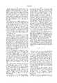
- FIG. 3Bis a detailed schematic diagram of the detector/drive circuitry 46 and calibration circuit 52 of the invention.
- the oscillator output signalis received on line 70 from the oscillator 48.
- the signalis coupled to the circuitry 46 by capacitors C9 and C10 and is applied across four-diode array D3.
- Nodes 74 and 76are connected to the sensor capacitances 30 and 28 (see FIG. 2).
- the result of this excitationis an alternating current through inductors L1 and L2.
- the levels of these inductor currentsare determined by the difference in capacitance between sensor capacitors 28 and 30.
- Inductor L1 in conjunction with capacitor C8forms an rf filter that eliminates the high-frequency component of the signal.
- the remaining circuitry in the detector/driver 46is used to detect the current through the inductors L1 and L2 to determine the sensor capacitances.
- the currentis detected by amplifier U3 and its associated circuitry, including capacitors C5 and C8 and resistors R7, R20, R30, R31 and adjustable resistors R2 and R3, all of which serve as a transconductance amplifier or current-to-voltage converter.
- the output of the amplifier at line 78is a DC voltage which indicates the average value of the current through the inductors and, therefore, the difference between capacitances 28 and 30.
- the DC voltage at line 78assumes a value within the range 0 to -10 volts, depending upon the pressure in the chamber.
- the zero-adjust circuitry of the calibration circuit 52 of the present inventionprovides calibration settings to provide an accurate voltage range indicative of the range of pressures within the chamber.
- Variable resistor R1 and resistor R32inject a zero-adjust current via zero-adjust line 54 at node 80 to adjust the zero-pressure condition for the amplifier.
- the positive and negative DC supplies, in this embodiment +10 and -10 volts,are applied across the variable resistor R1.
- the variable resistor R1is adjusted to set the output on line 78 to 0 volts.
- variable resistor R2 and resistors R30, R31, R20 of the zero-adjust circuitry of the calibration circuit 52provide fine zero adjust via zero-adjust line 54 and capacitor C5 provides filtering. This allows the invention to compensate for variations in sensor capacitances from unit to unit as well as various orientations of the sensor which affect displacement of the diaphragm.
- Variable resistor R3as part of the scale-adjust circuit of the calibration circuit 52 of the invention, uses a scale adjustment signal on line 56 to adjust the full-scale-pressure value for the system at the desired +10 volt level on line 68. At a full-scale-pressure condition, resistor R3 is adjusted such that the output on line 78 is at -10 VDC.
- the output signal on line 78is coupled to linearizing circuitry 60 and summing amplifier 62 to allow for compensation for non-linearities in the measurement and computation.
- the output from the detector/drive circuitry 46is summed via resistors R15, R18 and R19 and amplifier U4 with higher-order linearizing signals provided by the linearizing circuitry 60.
- the linearized outputis provided on line 68.
- the linearizing circuitryprovides two higher-order signals. As shown, the linearizing circuitry 60 provides a quadratic order correction signal on line 80 and a cubic order correction signal on line 82. The linearizing circuitry 60 generates these correction signals using a pair of multiplier circuits U5 and U6. In each multiplier, the output is given by ##EQU1##
- the output from the detector/drive circuitry 46 on line 78is connected to the X 1 and Y 1 inputs of multiplier U5; the X 2 input is connected to ground, and the Y 2 input is connected to a reference of -10V.
- the output of multiplier U5 provided on line 84is coupled to the summing amplifier 62 via an adjustable resistor R5.
- the resistor R5is used to adjust the level of quadratic correction signal coupled to the summing amplifier.
- the quadratic output on line 84is also coupled to the Y 1 input of the second multiplier U6.
- the X 1 input of the second multiplier U6is provided by the output from the detector drive circuitry 46.
- U6The X 2 input of U6 is connected to a reference of -5V, and the Y 2 input of U6 is grounded.
- U6provides a cubic output on line 86 which is the detector/drive output signal 78 cubed.
- Adjustable resistor R6sets the level of the cubic correction signal coupled to the summing amplifier circuitry 62.
- the resulting output provided at line 68is a calibrated linearized signal which provides an accurate indication of the difference in capacitance between sensor capacitors 28 and 30 corrected for the non-linearities previously discussed. This signal is used to determine the amount of deflection of the diaphragm and, therefore, the pressure in the chamber 12.
- FIG. 4is a schematic flow diagram illustrating the calibration and linearization processes used in the present invention.
- the quadratic and cubic variable resistors R5 and R6, respectivelyare initially adjusted to provide zero output signals at lines 80 and 82, respectively.
- the zero-pressure condition for the sensoris set.
- the zero-adjust circuitry described aboveis used to set the output of the detector/drive circuitry 46 at line 68 to 0 volts.
- the scale-adjust processis performed.
- the full-scale pressure conditionis set.
- the scale-adjust circuitry described aboveis adjusted to set the voltage output at line 68 to the full-scale level, e.g., +10 volts.
- step 104the system pressure is set to a mid-scale level.
- step 106the quadratic correction circuitry described above is adjusted to set the voltage output at line 68 shown in FIG. 3C to a mid-scale voltage level, e.g., +5 volts.
- steps 108 and 110the cubic correction term is adjusted to set the response on one side of the midpoint.
- the system pressurecan be set to a one-quarter scale level.
- the voltage outputis set to the desired level for linearity.
- the voltagecan be set at the one-quarter scale, e.g., +2.5 volts.
- the linearization processis performed outside of the measurement loop. That is, the quadratic and cubic adjustment signals are combined in the output after signal amplification. Therefore, the linearization signals have no effect on the zero-adjust and scale-adjust calibrations. Because these two signal settings are separate, the procedure for calibrating and then linearizing is far more efficient than in prior systems. Since the linearization process has no effect on the zero and scale adjusts, after linearization is performed, there is no need to go back and repeat zero and scale-adjust calibrations. Considerable setting time is eliminated.
- the pressure sensor of the inventionprovides numerous advantages over prior approaches.
- the detection/drive circuitry of the inventioncan be operated at high frequency, e.g., 1-10 MHZ, to produce higher capacitor and inductor current.
- the inventiondetects the high current through the inductor, the system has increased sensitivity and the signal-to-noise ratio of the system is improved.
- the inventioncan operate at high frequency, smaller components can be used, making the invention applicable in settings where small size is advantageous.
- the calibration and linearization processes of the inventionalso provide for a more accurate transducer than prior devices. Because the sensor of the invention is calibrated to adjust the voltage-versus-pressure relationship, non-linearities due to deflection of the transducer diaphragm are corrected. Also, because the linearization is performed open-loop, i.e., without feedback, wideband linearization is achieved. In addition, because the linearization is performed outside of the main system feedback loop, repetitive calibration and linearization steps are eliminated.
Landscapes
- Physics & Mathematics (AREA)
- General Physics & Mathematics (AREA)
- Measuring Fluid Pressure (AREA)
Abstract
Description
Claims (46)
Priority Applications (7)
| Application Number | Priority Date | Filing Date | Title |
|---|---|---|---|
| US08/835,668US5942692A (en) | 1997-04-10 | 1997-04-10 | Capacitive pressure sensing method and apparatus avoiding interelectrode capacitance by driving with in-phase excitation signals |
| TW087103174ATW434402B (en) | 1997-04-10 | 1998-03-05 | Capacitive pressure sensing method and apparatus |
| KR10-1999-7009297AKR100426461B1 (en) | 1997-04-10 | 1998-03-30 | A method of and apparatus for sensing pressure using capacitance measurement |
| EP98912130AEP0974043B1 (en) | 1997-04-10 | 1998-03-30 | Capacitive pressure sensing method and apparatus |
| JP54283898AJP3578774B2 (en) | 1997-04-10 | 1998-03-30 | Capacitive pressure sensing method and apparatus |
| PCT/US1998/006238WO1998045675A1 (en) | 1997-04-10 | 1998-03-30 | Capacitive pressure sensing method and apparatus |
| DE69841095TDE69841095D1 (en) | 1997-04-10 | 1998-03-30 | CAPACITIVE METHOD AND DEVICE FOR PRESSURE MEASUREMENT |
Applications Claiming Priority (1)
| Application Number | Priority Date | Filing Date | Title |
|---|---|---|---|
| US08/835,668US5942692A (en) | 1997-04-10 | 1997-04-10 | Capacitive pressure sensing method and apparatus avoiding interelectrode capacitance by driving with in-phase excitation signals |
Publications (1)
| Publication Number | Publication Date |
|---|---|
| US5942692Atrue US5942692A (en) | 1999-08-24 |
Family
ID=25270145
Family Applications (1)
| Application Number | Title | Priority Date | Filing Date |
|---|---|---|---|
| US08/835,668Expired - LifetimeUS5942692A (en) | 1997-04-10 | 1997-04-10 | Capacitive pressure sensing method and apparatus avoiding interelectrode capacitance by driving with in-phase excitation signals |
Country Status (7)
| Country | Link |
|---|---|
| US (1) | US5942692A (en) |
| EP (1) | EP0974043B1 (en) |
| JP (1) | JP3578774B2 (en) |
| KR (1) | KR100426461B1 (en) |
| DE (1) | DE69841095D1 (en) |
| TW (1) | TW434402B (en) |
| WO (1) | WO1998045675A1 (en) |
Cited By (28)
| Publication number | Priority date | Publication date | Assignee | Title |
|---|---|---|---|---|
| US6651505B2 (en)* | 2000-04-05 | 2003-11-25 | Teijin Seiki Co., Ltd. | Pressure detecting apparatus |
| US20030233205A1 (en)* | 2002-06-13 | 2003-12-18 | Horne Stephen F. | Apparatus and method for compensated sensor output |
| US20040032268A1 (en)* | 2002-08-16 | 2004-02-19 | Schulte John P. | Pressure measurement device including a capacitive pressure sensor in an amplifier feedback path |
| US6782754B1 (en) | 2000-07-07 | 2004-08-31 | Rosemount, Inc. | Pressure transmitter for clean environments |
| US20040187589A1 (en)* | 2003-03-22 | 2004-09-30 | Ferran Robert J. | Capacitance manometer having a relatively thick flush diaphragm under tension to provide low hysteresis |
| US20050252777A1 (en)* | 2004-04-01 | 2005-11-17 | Changming Li | Addressable chem/bio chip array |
| US20050262946A1 (en)* | 1997-12-22 | 2005-12-01 | Mks Instruments | Method for producing a pressure sensor for detecting small pressure differences and low pressures |
| US20060010983A1 (en)* | 2004-07-16 | 2006-01-19 | Rosemount Inc. | Pressure transducer with external heater |
| US20060156824A1 (en)* | 2005-01-14 | 2006-07-20 | Mks Instruments, Inc. | Turbo sump for use with capacitive pressure sensor |
| US7137301B2 (en) | 2004-10-07 | 2006-11-21 | Mks Instruments, Inc. | Method and apparatus for forming a reference pressure within a chamber of a capacitance sensor |
| US7141447B2 (en) | 2004-10-07 | 2006-11-28 | Mks Instruments, Inc. | Method of forming a seal between a housing and a diaphragm of a capacitance sensor |
| US20090120195A1 (en)* | 2007-11-08 | 2009-05-14 | Willcox Charles R | Pressure sensor |
| US20100024573A1 (en)* | 2008-07-29 | 2010-02-04 | Dodge Daverman | Single Sided Capacitive Force Sensor for Electronic Devices |
| US7679033B2 (en) | 2005-09-29 | 2010-03-16 | Rosemount Inc. | Process field device temperature control |
| US20110154905A1 (en)* | 2009-12-25 | 2011-06-30 | Industrial Technology Research Institute | Capacitive sensor and manufacturing method thereof |
| WO2011097249A1 (en) | 2010-02-02 | 2011-08-11 | Mks Instruments, Inc. | Capacitive pressure sensor |
| WO2013049490A2 (en) | 2011-09-29 | 2013-04-04 | Mks Instruments, Inc. | Capacitive pressure sensor with improved electrode structure |
| WO2013055882A1 (en) | 2011-10-11 | 2013-04-18 | Mks Instruments, Inc. | Pressure sensor |
| US20170292886A1 (en)* | 2016-04-06 | 2017-10-12 | City University Of Hong Kong | Electric device for detecting pressure |
| US10105103B2 (en) | 2013-04-18 | 2018-10-23 | Vectorious Medical Technologies Ltd. | Remotely powered sensory implant |
| US10205488B2 (en) | 2013-04-18 | 2019-02-12 | Vectorious Medical Technologies Ltd. | Low-power high-accuracy clock harvesting in inductive coupling systems |
| US10687716B2 (en) | 2012-11-14 | 2020-06-23 | Vectorious Medical Technologies Ltd. | Drift compensation for implanted capacitance-based pressure transducer |
| WO2020231613A1 (en)* | 2019-05-15 | 2020-11-19 | Sumitomo (Shi) Cryogenics Of America, Inc. | Bridge voltage inversion circuit for vacuum gauge and pressure gauge sensor having the voltage inversion circuit |
| US10874349B2 (en) | 2015-05-07 | 2020-12-29 | Vectorious Medical Technologies Ltd. | Deploying and fixating an implant across an organ wall |
| US11206988B2 (en) | 2015-12-30 | 2021-12-28 | Vectorious Medical Technologies Ltd. | Power-efficient pressure-sensor implant |
| US11287342B2 (en) | 2020-03-20 | 2022-03-29 | Mks Instruments, Inc. | Capacitance manometer with improved baffle for improved detection accuracy |
| CN118961004A (en)* | 2024-10-21 | 2024-11-15 | 悟通感控(北京)科技有限公司 | Anti-crosstalk sensing circuit and sensing method of capacitive pressure sensing array |
| CN118961003A (en)* | 2024-10-21 | 2024-11-15 | 悟通感控(北京)科技有限公司 | Sensing circuit and sensing method of capacitive pressure sensing array |
Families Citing this family (10)
| Publication number | Priority date | Publication date | Assignee | Title |
|---|---|---|---|---|
| JP4342122B2 (en)* | 2001-06-01 | 2009-10-14 | 株式会社豊田中央研究所 | Capacitance type physical quantity sensor and detection device |
| US6993973B2 (en)* | 2003-05-16 | 2006-02-07 | Mks Instruments, Inc. | Contaminant deposition control baffle for a capacitive pressure transducer |
| US8261619B2 (en) | 2005-11-28 | 2012-09-11 | Atlab Inc. | Time to digital converting circuit and pressure sensing device using the same |
| KR100725894B1 (en)* | 2005-11-28 | 2007-06-08 | 주식회사 애트랩 | Pressure sensor and pressure measuring method |
| GB2454130B (en)* | 2006-08-09 | 2011-05-25 | Mks Instr Inc | Constant power dissipation an capacitance pressure transducers |
| US7706995B2 (en)* | 2007-04-16 | 2010-04-27 | Mks Instr Inc | Capacitance manometers and methods relating to auto-drift correction |
| JP5855441B2 (en)* | 2011-01-07 | 2016-02-09 | 北陸電気工業株式会社 | Force sensor unit |
| US9562820B2 (en) | 2013-02-28 | 2017-02-07 | Mks Instruments, Inc. | Pressure sensor with real time health monitoring and compensation |
| DE102018105234B4 (en) | 2018-03-07 | 2020-08-20 | Ifm Electronic Gmbh | Method for operating a capacitive pressure measuring device |
| JP2020190468A (en)* | 2019-05-22 | 2020-11-26 | 株式会社堀場エステック | Pressure measuring device |
Citations (9)
| Publication number | Priority date | Publication date | Assignee | Title |
|---|---|---|---|---|
| US2178471A (en)* | 1937-05-24 | 1939-10-31 | Philips Nv | Device for oscillographing |
| US3497801A (en)* | 1967-02-23 | 1970-02-24 | Schwien Eng Inc | System for determining the difference in capacitance of two capacitors |
| US3783374A (en)* | 1972-04-07 | 1974-01-01 | Sundstrand Data Control | Capacitance difference detector circuit |
| US3948102A (en)* | 1974-07-31 | 1976-04-06 | The United States Of America As Represented By The Administrator Of The National Aeronautics And Space Administration | Trielectrode capacitive pressure transducer |
| US4398426A (en)* | 1981-07-02 | 1983-08-16 | Kavlico Corporation | Linear capacitive pressure transducer system |
| US4823603A (en)* | 1988-05-03 | 1989-04-25 | Vacuum General, Inc. | Capacitance manometer having stress relief for fixed electrode |
| US5087866A (en)* | 1991-05-22 | 1992-02-11 | Lucas Industries | Temperature compensating circuit for LVDT and control system |
| US5233875A (en)* | 1992-05-04 | 1993-08-10 | Kavlico Corporation | Stable capacitive pressure transducer system |
| US5656780A (en)* | 1996-03-28 | 1997-08-12 | Kavlico Corporation | Capacitive pressure transducer with an integrally formed front housing and flexible diaphragm |
Family Cites Families (3)
| Publication number | Priority date | Publication date | Assignee | Title |
|---|---|---|---|---|
| US4546651A (en)* | 1984-04-02 | 1985-10-15 | Hewlett-Packard Co. | Transducer coupling |
| US5237285A (en)* | 1991-10-18 | 1993-08-17 | Rosemount Inc. | Method and apparatus for capacitance temperature compensation and manufacturability in a dual plate capacitive pressure transmitter |
| US5571970A (en)* | 1993-03-30 | 1996-11-05 | Honda Motor Co., Ltd. | Pressure sensor |
- 1997
- 1997-04-10USUS08/835,668patent/US5942692A/ennot_activeExpired - Lifetime
- 1998
- 1998-03-05TWTW087103174Apatent/TW434402B/ennot_activeIP Right Cessation
- 1998-03-30WOPCT/US1998/006238patent/WO1998045675A1/enactiveIP Right Grant
- 1998-03-30EPEP98912130Apatent/EP0974043B1/ennot_activeExpired - Lifetime
- 1998-03-30KRKR10-1999-7009297Apatent/KR100426461B1/ennot_activeExpired - Fee Related
- 1998-03-30DEDE69841095Tpatent/DE69841095D1/ennot_activeExpired - Lifetime
- 1998-03-30JPJP54283898Apatent/JP3578774B2/ennot_activeExpired - Fee Related
Patent Citations (9)
| Publication number | Priority date | Publication date | Assignee | Title |
|---|---|---|---|---|
| US2178471A (en)* | 1937-05-24 | 1939-10-31 | Philips Nv | Device for oscillographing |
| US3497801A (en)* | 1967-02-23 | 1970-02-24 | Schwien Eng Inc | System for determining the difference in capacitance of two capacitors |
| US3783374A (en)* | 1972-04-07 | 1974-01-01 | Sundstrand Data Control | Capacitance difference detector circuit |
| US3948102A (en)* | 1974-07-31 | 1976-04-06 | The United States Of America As Represented By The Administrator Of The National Aeronautics And Space Administration | Trielectrode capacitive pressure transducer |
| US4398426A (en)* | 1981-07-02 | 1983-08-16 | Kavlico Corporation | Linear capacitive pressure transducer system |
| US4823603A (en)* | 1988-05-03 | 1989-04-25 | Vacuum General, Inc. | Capacitance manometer having stress relief for fixed electrode |
| US5087866A (en)* | 1991-05-22 | 1992-02-11 | Lucas Industries | Temperature compensating circuit for LVDT and control system |
| US5233875A (en)* | 1992-05-04 | 1993-08-10 | Kavlico Corporation | Stable capacitive pressure transducer system |
| US5656780A (en)* | 1996-03-28 | 1997-08-12 | Kavlico Corporation | Capacitive pressure transducer with an integrally formed front housing and flexible diaphragm |
Non-Patent Citations (4)
| Title |
|---|
| Harrison, D. R. and J. Dimeff (1973) "A Diode-Quad Bridge Circuit for Use with Capacitance Transducers" Rev. Sci. Instrum. 44 (10): 1468-1472. |
| Harrison, D. R. and J. Dimeff (1973) A Diode Quad Bridge Circuit for Use with Capacitance Transducers Rev. Sci. Instrum. 44 (10): 1468 1472.* |
| Kaplan, B. et al. (1978) "An Instrument for Continuously Measuring Capacitance Changes" IEEE Transactions on Instrumentation and Measurement IM-27 (1):43-45. |
| Kaplan, B. et al. (1978) An Instrument for Continuously Measuring Capacitance Changes IEEE Transactions on Instrumentation and Measurement IM 27 (1):43 45.* |
Cited By (49)
| Publication number | Priority date | Publication date | Assignee | Title |
|---|---|---|---|---|
| US7389697B2 (en) | 1997-12-22 | 2008-06-24 | Mks Instruments | Pressure sensor for detecting small pressure differences and low pressures |
| US7284439B2 (en) | 1997-12-22 | 2007-10-23 | Mks Instruments, Inc. | Method for producing a pressure sensor for detecting small pressure differences and low pressures |
| US20050262946A1 (en)* | 1997-12-22 | 2005-12-01 | Mks Instruments | Method for producing a pressure sensor for detecting small pressure differences and low pressures |
| US6651505B2 (en)* | 2000-04-05 | 2003-11-25 | Teijin Seiki Co., Ltd. | Pressure detecting apparatus |
| US6782754B1 (en) | 2000-07-07 | 2004-08-31 | Rosemount, Inc. | Pressure transmitter for clean environments |
| GB2405700B (en)* | 2002-06-13 | 2005-12-14 | Mks Instr Inc | Apparatus and method for compensated sensor output |
| US6687635B2 (en)* | 2002-06-13 | 2004-02-03 | Mks Instruments, Inc. | Apparatus and method for compensated sensor output |
| US20030233205A1 (en)* | 2002-06-13 | 2003-12-18 | Horne Stephen F. | Apparatus and method for compensated sensor output |
| WO2003106945A3 (en)* | 2002-06-13 | 2004-03-04 | Mks Instr Inc | Apparatus and method for compensated sensor output |
| GB2405700A (en)* | 2002-06-13 | 2005-03-09 | Mks Instr Inc | Apparatus and method for compensated sensor output |
| US6828802B2 (en)* | 2002-08-16 | 2004-12-07 | Rosemount Inc. | Pressure measurement device including a capacitive sensor in an amplifier feedback path |
| US20040032268A1 (en)* | 2002-08-16 | 2004-02-19 | Schulte John P. | Pressure measurement device including a capacitive pressure sensor in an amplifier feedback path |
| US6837112B2 (en) | 2003-03-22 | 2005-01-04 | Stec Inc. | Capacitance manometer having a relatively thick flush diaphragm under tension to provide low hysteresis |
| US20040187589A1 (en)* | 2003-03-22 | 2004-09-30 | Ferran Robert J. | Capacitance manometer having a relatively thick flush diaphragm under tension to provide low hysteresis |
| US8097134B2 (en)* | 2004-04-01 | 2012-01-17 | Nanyang Technological University | Addressable chem/bio chip array |
| US20050252777A1 (en)* | 2004-04-01 | 2005-11-17 | Changming Li | Addressable chem/bio chip array |
| US20060010983A1 (en)* | 2004-07-16 | 2006-01-19 | Rosemount Inc. | Pressure transducer with external heater |
| US7347099B2 (en) | 2004-07-16 | 2008-03-25 | Rosemount Inc. | Pressure transducer with external heater |
| US7624643B2 (en) | 2004-10-07 | 2009-12-01 | Mks Instruments, Inc. | Method and apparatus for forming a reference pressure within a chamber of a capacitance sensor |
| US7137301B2 (en) | 2004-10-07 | 2006-11-21 | Mks Instruments, Inc. | Method and apparatus for forming a reference pressure within a chamber of a capacitance sensor |
| US7141447B2 (en) | 2004-10-07 | 2006-11-28 | Mks Instruments, Inc. | Method of forming a seal between a housing and a diaphragm of a capacitance sensor |
| US7316163B2 (en) | 2004-10-07 | 2008-01-08 | Mks Instruments | Method of forming a seal between a housing and a diaphragm of a capacitance sensor |
| US20060156824A1 (en)* | 2005-01-14 | 2006-07-20 | Mks Instruments, Inc. | Turbo sump for use with capacitive pressure sensor |
| US7204150B2 (en)* | 2005-01-14 | 2007-04-17 | Mks Instruments, Inc. | Turbo sump for use with capacitive pressure sensor |
| US7679033B2 (en) | 2005-09-29 | 2010-03-16 | Rosemount Inc. | Process field device temperature control |
| US20090120195A1 (en)* | 2007-11-08 | 2009-05-14 | Willcox Charles R | Pressure sensor |
| US7779698B2 (en) | 2007-11-08 | 2010-08-24 | Rosemount Inc. | Pressure sensor |
| US20100024573A1 (en)* | 2008-07-29 | 2010-02-04 | Dodge Daverman | Single Sided Capacitive Force Sensor for Electronic Devices |
| US7784366B2 (en)* | 2008-07-29 | 2010-08-31 | Motorola, Inc. | Single sided capacitive force sensor for electronic devices |
| US20110154905A1 (en)* | 2009-12-25 | 2011-06-30 | Industrial Technology Research Institute | Capacitive sensor and manufacturing method thereof |
| US8104354B2 (en)* | 2009-12-25 | 2012-01-31 | Industrial Technology Research Institute | Capacitive sensor and manufacturing method thereof |
| WO2011097249A1 (en) | 2010-02-02 | 2011-08-11 | Mks Instruments, Inc. | Capacitive pressure sensor |
| DE112011100416T5 (en) | 2010-02-02 | 2012-12-06 | Mks Instruments Inc. | Capacitive pressure sensor |
| WO2013049490A2 (en) | 2011-09-29 | 2013-04-04 | Mks Instruments, Inc. | Capacitive pressure sensor with improved electrode structure |
| WO2013055882A1 (en) | 2011-10-11 | 2013-04-18 | Mks Instruments, Inc. | Pressure sensor |
| US8887575B2 (en) | 2011-10-11 | 2014-11-18 | Mks Instruments, Inc. | Pressure sensor |
| US10687716B2 (en) | 2012-11-14 | 2020-06-23 | Vectorious Medical Technologies Ltd. | Drift compensation for implanted capacitance-based pressure transducer |
| US10105103B2 (en) | 2013-04-18 | 2018-10-23 | Vectorious Medical Technologies Ltd. | Remotely powered sensory implant |
| US10205488B2 (en) | 2013-04-18 | 2019-02-12 | Vectorious Medical Technologies Ltd. | Low-power high-accuracy clock harvesting in inductive coupling systems |
| US10874349B2 (en) | 2015-05-07 | 2020-12-29 | Vectorious Medical Technologies Ltd. | Deploying and fixating an implant across an organ wall |
| US11206988B2 (en) | 2015-12-30 | 2021-12-28 | Vectorious Medical Technologies Ltd. | Power-efficient pressure-sensor implant |
| US10054507B2 (en)* | 2016-04-06 | 2018-08-21 | City University Of Hong Kong | Electric device for detecting pressure |
| US20170292886A1 (en)* | 2016-04-06 | 2017-10-12 | City University Of Hong Kong | Electric device for detecting pressure |
| WO2020231613A1 (en)* | 2019-05-15 | 2020-11-19 | Sumitomo (Shi) Cryogenics Of America, Inc. | Bridge voltage inversion circuit for vacuum gauge and pressure gauge sensor having the voltage inversion circuit |
| US20220196502A1 (en)* | 2019-05-15 | 2022-06-23 | Sumitomo (Shi) Cryogenics Of America, Inc. | Bridge voltage inversion circuit for vacuum gauge and pressure gauge sensor having the voltage inversion circuit |
| US11906380B2 (en)* | 2019-05-15 | 2024-02-20 | Sumitomo (Shi) Cryogenics Of America, Inc. | Bridge voltage inversion circuit for vacuum gauge and pressure gauge sensor having the voltage inversion circuit |
| US11287342B2 (en) | 2020-03-20 | 2022-03-29 | Mks Instruments, Inc. | Capacitance manometer with improved baffle for improved detection accuracy |
| CN118961004A (en)* | 2024-10-21 | 2024-11-15 | 悟通感控(北京)科技有限公司 | Anti-crosstalk sensing circuit and sensing method of capacitive pressure sensing array |
| CN118961003A (en)* | 2024-10-21 | 2024-11-15 | 悟通感控(北京)科技有限公司 | Sensing circuit and sensing method of capacitive pressure sensing array |
Also Published As
| Publication number | Publication date |
|---|---|
| DE69841095D1 (en) | 2009-10-08 |
| KR20010006217A (en) | 2001-01-26 |
| EP0974043A4 (en) | 2002-05-02 |
| TW434402B (en) | 2001-05-16 |
| EP0974043B1 (en) | 2009-08-26 |
| JP3578774B2 (en) | 2004-10-20 |
| WO1998045675A1 (en) | 1998-10-15 |
| EP0974043A1 (en) | 2000-01-26 |
| KR100426461B1 (en) | 2004-04-13 |
| JP2001519031A (en) | 2001-10-16 |
Similar Documents
| Publication | Publication Date | Title |
|---|---|---|
| US5942692A (en) | Capacitive pressure sensing method and apparatus avoiding interelectrode capacitance by driving with in-phase excitation signals | |
| US9911577B2 (en) | Arrangement for plasma processing system control based on RF voltage | |
| US4816743A (en) | Method and apparatus for the identification of oscillatory properties as well as for the operation of a piezo-electric tranducer | |
| JPH0431051B2 (en) | ||
| JPS6237440B1 (en) | ||
| US20040212400A1 (en) | High-frequency detection method and high-frequency detection circuit | |
| US5051743A (en) | High precision, high frequency current sensing and analog signal decoding network | |
| US4807477A (en) | Capacitive temperature compensation for a pressure sensor | |
| EP0079955B1 (en) | Impedance measurement circuit | |
| GB2217861A (en) | Determining permittivity | |
| WO2004017036A2 (en) | Pressure measurement device including a capacitive pressure sensor in an amplifier feedback path | |
| US6448792B1 (en) | Sensor for edge position of electro-conductive material | |
| US20220130642A1 (en) | Methods and apparatus for processing a substrate | |
| US4748852A (en) | Transmitter with an improved span adjustment | |
| JPH04279803A (en) | Method of operation setting for measurement device | |
| US4597288A (en) | Barometer | |
| JP3329480B2 (en) | Differential pressure measuring device | |
| JPH0448166B2 (en) | ||
| US6611174B1 (en) | Self-compensated transimpedance amplifier | |
| US20020178802A1 (en) | Scanning probe microscope and method of processing signals in the same | |
| JP3161716B2 (en) | Capacitance detection circuit | |
| JPH06148231A (en) | Yaw rate sensor temperature compensation method and temperature compensation device | |
| EP0151575A1 (en) | REACTIVE MEASURING CIRCUIT WITH INCREASED LINEARITY. | |
| JPH05249165A (en) | Semiconductor potential sensor | |
| JPH03214024A (en) | Capacitance type length measuring machine |
Legal Events
| Date | Code | Title | Description |
|---|---|---|---|
| AS | Assignment | Owner name:MKS INSTRUMENTS, INC., MASSACHUSETTS Free format text:ASSIGNMENT OF ASSIGNORS INTEREST;ASSIGNORS:HAASE, WAYNE C.;CHIZINSKI, PAUL M.;MINDLIN, LEONID;AND OTHERS;REEL/FRAME:008518/0009 Effective date:19970409 | |
| STCF | Information on status: patent grant | Free format text:PATENTED CASE | |
| CC | Certificate of correction | ||
| FEPP | Fee payment procedure | Free format text:PAYOR NUMBER ASSIGNED (ORIGINAL EVENT CODE: ASPN); ENTITY STATUS OF PATENT OWNER: LARGE ENTITY | |
| FPAY | Fee payment | Year of fee payment:4 | |
| FPAY | Fee payment | Year of fee payment:8 | |
| FPAY | Fee payment | Year of fee payment:12 | |
| AS | Assignment | Owner name:DEUTSCHE BANK AG NEW YORK BRANCH, NEW YORK Free format text:SECURITY AGREEMENT;ASSIGNORS:MKS INSTRUMENTS, INC.;NEWPORT CORPORATION;REEL/FRAME:038663/0265 Effective date:20160429 Owner name:BARCLAYS BANK PLC, NEW YORK Free format text:SECURITY AGREEMENT;ASSIGNORS:MKS INSTRUMENTS, INC.;NEWPORT CORPORATION;REEL/FRAME:038663/0139 Effective date:20160429 | |
| AS | Assignment | Owner name:MKS INSTRUMENTS, INC., MASSACHUSETTS Free format text:RELEASE BY SECURED PARTY;ASSIGNOR:DEUTSCHE BANK AG NEW YORK BRANCH;REEL/FRAME:048226/0095 Effective date:20190201 Owner name:NEWPORT CORPORATION, CALIFORNIA Free format text:RELEASE BY SECURED PARTY;ASSIGNOR:DEUTSCHE BANK AG NEW YORK BRANCH;REEL/FRAME:048226/0095 Effective date:20190201 | |
| AS | Assignment | Owner name:ELECTRO SCIENTIFIC INDUSTRIES, INC., OREGON Free format text:RELEASE BY SECURED PARTY;ASSIGNOR:BARCLAYS BANK PLC;REEL/FRAME:062739/0001 Effective date:20220817 Owner name:NEWPORT CORPORATION, MASSACHUSETTS Free format text:RELEASE BY SECURED PARTY;ASSIGNOR:BARCLAYS BANK PLC;REEL/FRAME:062739/0001 Effective date:20220817 Owner name:MKS INSTRUMENTS, INC., MASSACHUSETTS Free format text:RELEASE BY SECURED PARTY;ASSIGNOR:BARCLAYS BANK PLC;REEL/FRAME:062739/0001 Effective date:20220817 |