US5941885A - Tools for use in installing osteosynthesis apparatus utilizing set screw with break-off head - Google Patents
Tools for use in installing osteosynthesis apparatus utilizing set screw with break-off headDownload PDFInfo
- Publication number
- US5941885A US5941885AUS08/726,828US72682896AUS5941885AUS 5941885 AUS5941885 AUS 5941885AUS 72682896 AUS72682896 AUS 72682896AUS 5941885 AUS5941885 AUS 5941885A
- Authority
- US
- United States
- Prior art keywords
- set screw
- socket
- handle
- head
- bore
- Prior art date
- Legal status (The legal status is an assumption and is not a legal conclusion. Google has not performed a legal analysis and makes no representation as to the accuracy of the status listed.)
- Expired - Lifetime
Links
- 238000003780insertionMethods0.000claimsabstractdescription34
- 230000037431insertionEffects0.000claimsabstractdescription34
- 239000007943implantSubstances0.000claimsabstractdescription27
- 210000005069earsAnatomy0.000claimsdescription12
- 238000004891communicationMethods0.000claimsdescription10
- 230000014759maintenance of locationEffects0.000claimsdescription5
- 230000006835compressionEffects0.000claimsdescription3
- 238000007906compressionMethods0.000claimsdescription3
- 241000269627Amphiuma meansSpecies0.000claims1
- 210000000988bone and boneAnatomy0.000description80
- 230000002093peripheral effectEffects0.000description11
- 230000008878couplingEffects0.000description4
- 238000010168coupling processMethods0.000description4
- 238000005859coupling reactionMethods0.000description4
- 210000002105tongueAnatomy0.000description4
- 238000004140cleaningMethods0.000description3
- 239000011248coating agentSubstances0.000description2
- 238000000576coating methodMethods0.000description2
- 238000009434installationMethods0.000description2
- 210000002445nippleAnatomy0.000description2
- 230000000087stabilizing effectEffects0.000description2
- 239000000126substanceSubstances0.000description2
- 238000001356surgical procedureMethods0.000description2
- 238000002513implantationMethods0.000description1
- 230000007794irritationEffects0.000description1
- 238000000034methodMethods0.000description1
- 230000000399orthopedic effectEffects0.000description1
Images


Classifications
- A—HUMAN NECESSITIES
- A61—MEDICAL OR VETERINARY SCIENCE; HYGIENE
- A61B—DIAGNOSIS; SURGERY; IDENTIFICATION
- A61B17/00—Surgical instruments, devices or methods
- A61B17/56—Surgical instruments or methods for treatment of bones or joints; Devices specially adapted therefor
- A61B17/58—Surgical instruments or methods for treatment of bones or joints; Devices specially adapted therefor for osteosynthesis, e.g. bone plates, screws or setting implements
- A61B17/68—Internal fixation devices, including fasteners and spinal fixators, even if a part thereof projects from the skin
- A61B17/70—Spinal positioners or stabilisers, e.g. stabilisers comprising fluid filler in an implant
- A61B17/7074—Tools specially adapted for spinal fixation operations other than for bone removal or filler handling
- A61B17/7076—Tools specially adapted for spinal fixation operations other than for bone removal or filler handling for driving, positioning or assembling spinal clamps or bone anchors specially adapted for spinal fixation
- A61B17/7082—Tools specially adapted for spinal fixation operations other than for bone removal or filler handling for driving, positioning or assembling spinal clamps or bone anchors specially adapted for spinal fixation for driving, i.e. rotating, screws or screw parts specially adapted for spinal fixation, e.g. for driving polyaxial or tulip-headed screws
- A—HUMAN NECESSITIES
- A61—MEDICAL OR VETERINARY SCIENCE; HYGIENE
- A61B—DIAGNOSIS; SURGERY; IDENTIFICATION
- A61B17/00—Surgical instruments, devices or methods
- A61B17/56—Surgical instruments or methods for treatment of bones or joints; Devices specially adapted therefor
- A61B17/58—Surgical instruments or methods for treatment of bones or joints; Devices specially adapted therefor for osteosynthesis, e.g. bone plates, screws or setting implements
- A61B17/68—Internal fixation devices, including fasteners and spinal fixators, even if a part thereof projects from the skin
- A61B17/70—Spinal positioners or stabilisers, e.g. stabilisers comprising fluid filler in an implant
- A61B17/7074—Tools specially adapted for spinal fixation operations other than for bone removal or filler handling
- A61B17/7076—Tools specially adapted for spinal fixation operations other than for bone removal or filler handling for driving, positioning or assembling spinal clamps or bone anchors specially adapted for spinal fixation
- A—HUMAN NECESSITIES
- A61—MEDICAL OR VETERINARY SCIENCE; HYGIENE
- A61B—DIAGNOSIS; SURGERY; IDENTIFICATION
- A61B17/00—Surgical instruments, devices or methods
- A61B17/56—Surgical instruments or methods for treatment of bones or joints; Devices specially adapted therefor
- A61B17/58—Surgical instruments or methods for treatment of bones or joints; Devices specially adapted therefor for osteosynthesis, e.g. bone plates, screws or setting implements
- A61B17/68—Internal fixation devices, including fasteners and spinal fixators, even if a part thereof projects from the skin
- A61B17/70—Spinal positioners or stabilisers, e.g. stabilisers comprising fluid filler in an implant
- A61B17/7074—Tools specially adapted for spinal fixation operations other than for bone removal or filler handling
- A61B17/7091—Tools specially adapted for spinal fixation operations other than for bone removal or filler handling for applying, tightening or removing longitudinal element-to-bone anchor locking elements, e.g. caps, set screws, nuts or wedges
- A—HUMAN NECESSITIES
- A61—MEDICAL OR VETERINARY SCIENCE; HYGIENE
- A61B—DIAGNOSIS; SURGERY; IDENTIFICATION
- A61B90/00—Instruments, implements or accessories specially adapted for surgery or diagnosis and not covered by any of the groups A61B1/00 - A61B50/00, e.g. for luxation treatment or for protecting wound edges
- A61B90/03—Automatic limiting or abutting means, e.g. for safety
- A61B2090/037—Automatic limiting or abutting means, e.g. for safety with a frangible part, e.g. by reduced diameter
Definitions
- the present inventionrelates to tools for use in surgically installing apparatus for correcting orthopedic deformities in a patient and, in particular, to tools specifically designed to facilitate installation of a spinal osteosynthesis system in a patent utilizing a unique set screw having a break-off head.
- Bone screwsincluding sacral screws and pedicle screws, transverse connectors and bone hooks for stabilizing and adjusting spinal alignment.
- the bone screws, transverse connectors, bone hooks and related items which are intended for use in connecting the rods to the bone and to facilitate adjustment of the rodsmay collectively be referred to as hardware or implants.
- the bone screwshave a spinal rod receiving bore extending through a ring or head of the screw. The screws are secured in the vertebra at desired locations and a spinal rod is then extended through the spinal rod bore in each bone screw.
- Set screwsinserted in threaded bores extending through the wall of the screw ring, preferably perpendicular to the axis of the spinal rod bore, are tightened to fix the translational and rotational relationship of the rods within the bores.
- the rodsmay then be bent or formed to support the spine in a desired manner or to exert the desired corrective or stabilizing forces on the spine.
- a slightly more complicated systemuses transverse connectors in association with the bone screws to secure the spinal rods.
- the transverse connectorsinclude an arm and a head.
- the headhas a spinal rod bore extending therethrough and the arm is normally equivalent in diameter to the spinal rod.
- the arm of the connectoris inserted through the spinal rod bore in the pedicle screw then the spinal rod may be inserted through the spinal rod bore in the transverse connectors.
- a threaded boreextends through the head of the connector perpendicular to the axis of the spinal rod bore.
- the set screwsare inserted through the threaded bores and tightened to fix the relative position of the rod within the spinal rod bore and set screws are inserted in the threaded bores and tightened to fix the position of the transverse connector with respect to the pedicle screws.
- the pedicle screws, transverse connectors, bone hooks or related implants or hardwaremay be of the closed end type as discussed above or of an open end type wherein the head of the screw or connector generally incorporates a U-shaped channel or groove, an upper end of which may be closed off by a cap or saddle to form the spinal rod bore.
- the threaded set screw boretypically extends through the cap.
- a preferable aspect of any osteosynthesis apparatusis to provide a system wherein the components may be readily manipulated to facilitate relatively easy and rapid installment or disassembly.
- Manipulation of small headed set screwsprovides a significant challenge to surgeons installing currently available systems, especially when working in the close confines of an operative site. Some techniques require the surgeon to operate through an opening that is just sufficient in size to receive the parts of the apparatus to be assembled and the tools with no room provided for the surgeon's hands or fingers. Due to the nature of use of the set screw, it is important that the set screw be relatively small to reduce impact on the patient and irritation caused by the screw. The small size of set screws often makes them difficult to grasp and manipulate.
- set screwsare being used in which the head of the screw breaks off or shears off after insertion such that generally no or only a small portion of the set screw extends above or beyond the threaded bore into which it is inserted.
- the broken off headshould be readily captured and removed from the site of the operation.
- the present inventioncomprises a set of tools for use in installing an osteosynthesis apparatus utilizing a set screw with a break off head.
- the set screwcomprises a head of polygonal and preferably hexagonal external cross-section, and a lower portion having a threaded outer surface.
- a peripheral notchis formed between the head and the lower threaded portion of the set screw.
- a cylindrical axially extending boreis formed in the set screw and extends through the head and partially through the lower portion.
- the set screwis adapted for use in securing a rod in the bore of a ring from translational or rotational motion.
- the ringis of the type formed in the head of a bone screw, the head of a connector secured to the bone screw or the head of a hook.
- the rodis of the type including spinal rods or the rod portion of a connector.
- a threaded set screw boreextends radially through a wall of the ring perpendicular to the axis of the rod receiving bore.
- the tools of the present inventionare generally socket type tools having a handle, a stem and a head with a socket formed therein.
- a projectionextends axially into the socket from an inner surface thereof and has an outwardly biasing element thereon.
- the projectionis sized for insertion into at least a portion of the bore extending through the set screw head, when the set screw head is positioned in the socket.
- the outwardly biasing elementbiases against the internal wall of the head defining the upper section of the cylindrical bore, in order to grip the head when inserted therein.
- the socketis of hexagonal internal cross-section and is sized to snugly and matingly receive and conform to the hexagonal head of the set screw to facilitate driving of the set screw.
- the set screw driverhaving a set screw secured within the socket, can then be used to install a set screw in the threaded set screw bore of the ring, and to tighten down the set screw to engage and bite into the outer surface of the rod.
- the set screw driverhaving a set screw secured within the socket, can then be used to install a set screw in the threaded set screw bore of the ring, and to tighten down the set screw to engage and bite into the outer surface of the rod.
- Continued tightening of the set screw to a preselected torquecauses the head to shear off along the radially inner circular groove of the peripheral notch so as to break comparatively smoothly along a plane defined by the circular groove. Biasing of the outwardly biasing element against the internal wall of the set screw head holds the head after breaking on the projection to permit retrieval of the head.
- a second toolwhich is a closed end screw driver, is adapted to drive bone screws of the closed end type with a set screw pre-loaded in a set screw receiving bore thereof.
- the head of the bone screw driverhas depending extensions, ears or tabs adapted to engage opposite sides or faces of the bone screw on an upper end thereof to facilitate driving of the bone screw.
- a third toolwhich is a cap inserter, is adapted for inserting caps on bone screws, connectors or bone hooks with a set screw pre-loaded in a set screw receiving bore.
- the head of the cap inserterincludes a single depending projection, ear or tab adapted to abut against a rear face of a cap having a set screw pre-loaded in the set screw receiving bore.
- the head of a set screw that has previously been threaded onto a capis inserted into the socket of the cap inserter such that the projection extends into the set screw bore and the depending tab abuts against a rear face of the cap.
- the cap installer socketis cylindrical and slightly wider than the set screw.
- the interference fit produced between the outwardly biasing element on the projection and the internal wall of the set screw headreleasably secures the set screw and the cap onto the cap installer. Abutment of the depending tab against the rear surface of the cap prevents rotation of the cap relative to the set screw during manipulation of the tool with the cap attached thereto.
- the tool with the cap attached theretocan then be used to install the cap to the open end of a bone screw, a connector or a bone hook with the set screw already partially threaded therein.
- Another tool of the present inventioncomprises a threaded implant installer comprising a stem having a handle secured at one end and threaded at an opposite end.
- the threaded endis sized for insertion into and threaded coupling with the threaded set screw bore in a bone screw or other implant such as a hook or connector.
- the threaded bone screw driveris particularly useful in minimally invasive type surgery wherein the implant is inserted into the body through a relatively small incision.
- the threaded coupling between the tool and the bone screwprevents the screw from being pulled off the driver, if the screw must be retracted through the incision.
- Another tool of the present inventioncomprises forceps having first and second arms pivotally secured together in a scissor like fashion.
- Each armincludes a gripping portion and a handle portion.
- Each gripping portionincludes a socket half formed therein such that when the gripping portions of the first and second arms are advanced together the socket halves form a socket which is adapted to receive a portion of an osteosynthesis implant with a set screw secured thereto.
- One of the socket halvesincludes a ridge extending thereacross and dividing the socket halve into an inner portion and an outer portion. The inner portion of the socket half is adapted to receive the set screw and the outer portion is adapted to receive the portion of the implant to which the set screw is secured.
- the ridgeextends into a gap between a lower end of the head of the set screw and the end of the implant to which the set screw is attached.
- the ridgeinterferingly prevents the set screw and therefore the implant to which it is attached from being removed from the socket when the implant and the set screw are grasped by the grasping portions of the forceps.
- the objects and advantages of the inventioninclude: to provide a set of tools for use in installing an osteosynthesis apparatus utilizing a set screw with a break-off head; to provide such a set of tools which facilitate manipulation of the components of the osteosynthesis apparatus; to provide such a set of tools which are adapted to grip the head of the set screw; to provide such a set of tools having a handle, a stem and a head with a socket formed therein and having a projection extending into the socket for insertion into a cylindrical bore of a set screw; to provide such a set of tools wherein the projection incorporates an outwardly biasing element for engaging the inner wall of the set screw; to provide such a set of tools wherein the projection is removable from said socket to facilitate cleaning; to provide such a set of tools wherein the projection is formed on the end of a rod insertable through a bore extending through the handle and stem of the tool; to provide such a system incorporating a tool which facilitates the driving of set screws and retrieval of the broken off heads; to provide such a system
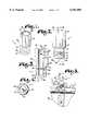
- FIG. 1is a perspective view of a set screw having a break-off head for use in an osteosynthesis apparatus.
- FIG. 2is an enlarged front elevational view of the set screw as shown in FIG. 1.
- FIG. 3is a cross-sectional view of the set screw, taken along line 3--3 of FIG. 2.
- FIG. 4is a cross sectional view of the set screw, taken generally along line 4--4 of FIG. 2.
- FIG. 5is a front elevational view on a reduced scale of the set screw showing a lower portion of the set screw engaging a spinal rod secured within a spinal rod bore in a bone screw and showing a head of the set screw broken off.
- FIG. 6is a side elevational view on a reduced scale of a bone screw secured within a vertebra and with portions broken away to show a lower portion of the set screw secured within the bone screw.
- FIG. 7is a fragmentary and exploded front elevational view of a torque wrench of the present invention showing a torque wrench tool body and a set screw engaging insert with one of the set screws secured thereto and with portions of the tool body broken away to show interior detail.
- FIG. 8is an enlarged and fragmentary view of the set screw engaging insert.
- FIG. 9is an enlarged and fragmentary cross-sectional view, taken generally along line 9--9 of FIG. 7, with portions of the set screw removed to show detail thereof.
- FIG. 10is an enlarged and fragmentary bottom plan view of the torque wrench without a set screw secured thereto.
- FIG. 11is a fragmentary front elevational view of the torque wrench with portions broken away to show detail and showing the set screw engaging insert advanced relative to the torque wrench tool body to eject a broken-off head portion of the set screw from a socket of the torque wrench tool body.
- FIG. 12is a fragmentary and exploded front elevational view of a closed end screw driver of the present invention showing a tool body and a set screw engaging insert with a closed end bone screw and with portions of the tool body broken away to show interior detail.
- FIG. 13is an enlarged and fragmentary view of the set screw engaging insert, taken generally along line 13--13 of FIG. 12.
- FIG. 14is an enlarged and fragmentary cross-sectional view, taken generally along line 14--14 of FIG. 12, with portions of a set screw broken away to show detail thereof and showing the closed end screw in phantom lines.
- FIG. 15is a fragmentary front elevational view of a cap inserter of the present invention showing a set screw engaging insert secured within a tool body.
- FIG. 16is a fragmentary side elevational view of the cap inserter, view taken along line 16--16 of FIG. 15.
- FIG. 17is an enlarged and fragmentary bottom plan view of the cap inserter.
- FIG. 18is an enlarged and fragmentary exploded view of the cap inserter having a set screw to be inserted into the set screw engaging insert and wherein the set screw is in turn positioned to be inserted into a saddle cap which is positioned to be inserted into an open ended osteosynthesis connector which is positioned to be secured to an osteosynthesis rod.
- FIG. 19is an enlarged and fragmentary side elevational view of the cap insert and other apparatus shown in FIG. 18, taken generally along line 19--19 of FIG. 18, subsequent to assembly.
- FIG. 20is fragmentary front elevational view of an alternative embodiment of a modified torque wrench of the present invention having a set screw engaging insert secured within a tool body.
- FIG. 21is a bottom plan view of the modified torque wrench.
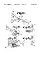
- FIG. 22is an exploded front elevational view of a threaded bone screw driver of the present invention coupled with a bone screw.
- FIG. 23is an exploded and fragmentary front elevational view of the threaded bone screw driver as shown in FIG. 22 coupled with a cap.
- FIG. 24is an exploded and fragmentary front elevational view of the threaded bone screw driver as shown in FIG. 22 coupled with a hook.
- FIG. 25is a perspective view of a pair of forceps of the present invention with a hook secured thereby.
- FIG. 26is an enlarged and fragmentary view of the forceps shown in FIG. 25 shown in an open position.
- FIG. 27is an enlarged and fragmentary view of the forceps taken generally along line 27--27 of FIG. 25.
- FIG. 28is a view similar to FIG. 5 showing use of an easy out type tool to remove a lower portion of the set screw from a bone screw.
- the reference numeral 1refers to a set screw for use in osteosynthesis apparatus 2 and, in particular, for use in spinal osteosynthesis apparatus 2.
- the set screw 1is adapted for use in securing an rod 5 in a rod receiving bore 6 of a head or ring 7, from both translational and rotational motion.
- the ring 7is of the type formed in the head of a closed end bone screw 10 or the head of a conventional connector or bone hook secured to the bone screw 10.
- the bone screws 10are normally referred to as sacral screws or pedicle screws.
- the rod 5is of the type including spinal rods for surgical implantation into a patent or may also be the arm or rod portion of a connector or bone hook which collectively are referred to herein as osteosynthesis rods.
- a threaded set screw receiving bore 11extends radially through the ring 7 perpendicular to the axis of the rod receiving bore 6.
- the set screw 1as shown in FIGS. 1 through 4, comprises a head 20, of hexagonal external cross-section, and a lower portion 22, having a threaded outer surface 23.
- the head 20is relatively elongated to facilitate manipulation of the set screw 1.
- a point 28is formed on a lower surface 29 of the set screw 1 centrally thereof so as to extend outwardly along the axis of rotation of the set screw 1.
- a peripheral notch 32is formed between the head 20 and the lower threaded portion 22 of the set screw 1 on an outer surface 33 of the set screw 1 the innermost part of the notch 32 forming a circular groove defining a plane that is generally perpendicular to the axis of rotation of the set screw 1.
- a cylindrical bore or projection receiving bore 35comprising an upper bore section 36 and a lower bore section 37 is formed in the set screw 1 and extends through the head 20 and partially through the set screw lower portion 22.
- the upper bore section 36generally extends coextensive with the head 20 of the screw 1 and the lower bore section 37 extends partially through the lower portion 22 of the screw 1.
- the lower bore section 37preferably has a slightly smaller diameter than the upper bore section 36.
- a reverse thread 40is formed in an internal wall 41 of the set screw 1 defining the lower bore section 37 near an upper end 42 thereof.
- a drive slot 46extends across a top end 47 of the set screw head 20 having sections that are diagonally spaced on opposite sides of the top end 47.
- the set screw 1is preferably driven by a hexagonal socket type wrench as described in more detail below.
- the drive slot 46is adapted to receive a screw-driver type tool for driving the screw 1 into the set screw receiving bore 11 in some applications.
- the set screw 1may be inserted in the ring 7 after the bone screw 10 is inserted into a bone 50 of a patient and after a rod 5 is inserted through the rod receiving bore 6.
- the set screw 1is further driven through the set screw receiving bore 11 until the point 28 engages and bites into the rod 5. Further driving or tightening of the set screw 1 causes the head 20 of the set screw 1 to shear off at a preselected torque along the narrowest part of the peripheral notch 32, as shown in FIG. 5.
- the lower portion 22 of the set screw 1is preferably sized such that, after the head 20 is sheared off, an upper end 55 of the set screw lower portion 22 is generally flush with an upper edge or upper end 57 of the ring 7 such that no portion, or only a relatively small portion, of the set screw lower portion 22 extends beyond the upper end 57 of the ring 7. Further, after the head 20 is sheared off, the upper end 55 of the set screw lower portion 22 is generally free from burrs or jagged edges.
- a set screw torque wrench 60is alternatively used to drive the set screws 1, as noted above, and retrieve the sheared off heads 20 of the screws 1.
- the torque wrench 60comprises a tool body 61 having a handle 64, a stem 65 and a head 66 with a socket 67 formed therein.
- the socket 67is internally hexagonal in shape and sized and shaped to receive and conform to the head 20 of a set screw 1.
- the handle 64is generally cylindrical and extends perpendicular to the stem 65.
- An insert receiving bore 69comprising a first bore portion or handle cavity 70 and a second bore portion or stem bore 71 extends through the tool body 61 and in communication with the socket 67.
- the handle cavity 70is formed in the handle 64, perpendicular to a longitudinal axis of the handle 64, and extends substantially through the handle 64 and opening at an upper end 72 thereof.
- the stem bore 71is formed in the stem 65 and opens into the handle cavity 70 at one end and the socket 67 at an opposite end.
- the handle cavity 70is of larger diameter than the stem bore 71.
- a set screw engaging insert 74comprising a shaft 75 having a cap 76 secured at one end and a nipple or projection 77 extending axially away from an opposite end thereof is sized for insertion into and through the insert receiving bore 69.
- the shaft 75is cylindrical.
- the cap 76is also cylindrical and of a larger diameter than the shaft 75 and is sized for insertion into the handle cavity 70.
- a spring loaded ball detent 80is secured to or positioned on the cap 76 on a peripheral surface 81 thereof and biasingly engages an inner wall 82 of the handle 64 defining the first bore 70.
- the spring loaded ball detent 80functions as securement means for removably securing the cap 76 to the handle 64 and providing resistance to removal of the insert 74 from the tool body 61 that can be overcome by manual pressure.
- the insert 74is preferably designed to be removable from the tool body 61 in particular to facilitate cleaning. It is foreseen that other means could be used for removably securing the cap 76 to the handle 64, including other resilient biasing members or structure which provides an interference fit.
- a compression type coil spring 85is positioned in circumscribing relationship with the shaft 75.
- the spring 85is positioned between a lower surface 86 of the cap 76 and a spring seat or shoulder 87 formed in the handle 64 at the intersection of the handle cavity 70 and the stem bore 71.
- the projection 77is generally positioned within the socket 67.
- the projection 77is sized for insertion into the cylindrical bore 35 in the set screw 1, when the set screw head 20 is positioned in the socket 67.
- a peripheral groove 90extends around the projection 77.
- a split washer type spring 91which is compressible is secured to the projection 77 in the peripheral groove 90, such that a portion of the split washer type spring 91 extends beyond a peripheral edge of the projection 77.
- the outer diameter of the split washer type spring 91 in an uncompressed stateis slightly greater than the diameter of the bore 35 in the set screw 1.
- a chamfer 94at an upper end of the set screw 1, facilitates compression of the split washer type spring 91 to permit further insertion of the projection 77 into the bore 35.
- the compressed split washer type spring 91biases against an internal wall 95 of the set screw head 20, in order to grip the head 20.
- the split washer type spring 91functions as a resilient biasing member or more generally as retention means for releasably securing the set screw 1 to the projection 77. It is foreseen that a wide variety of resilient biasing members and retention means could be used in association with the projection 77 for securing a set screw 1 thereto including possibly a spring loaded ball detent, a flat spring, a rubber washer or O-ring secured around the projection, coating the projection 77 or the bore 35 in the set screw 1 with a slightly tacky substance, magnetizing the projection 77 or the set screw 1, forming structure on the projection 77 or set screw 1 to create an interference fit or forming the projection 77 of adjacent biasable strips or segments such that the entire projection is biasable.
- Drive flanges, ears, projections or tabs 96extend radially outward from the projection 77 at an upper end thereof and on opposite sides of the projection 77.
- the tabs 96are sized for insertion into the drive slot 46 extending across the top end 47 of a set screw 1.
- the torque wrench 60is used to tighten a set screw 1 until a preselected torque is applied to the set screw 1 at which time the head 20 breaks off.
- the head 20is held by the projection 77 and may be removed from an operating cavity (not shown) in a patient by simply withdrawing the wrench 60.
- the cap 65may be pressed further into the first bore 70 against the biasing force of the spring 85 to advance the projection 77, with the set screw head 20 secured thereto, so as to extend out of the socket 67, to permit easy manual removal of the set screw head 20 from the projection 77.
- the set screw 1may also be pre-loaded into the bone screw 10, or related structure, prior to insertion into the patient.
- the set screw 1may be manually partially inserted in the set screw receiving bore 11 of a bone screw 20 or a connector before insertion in a patient and rotated a sufficient number of turns such that the set screw 1 is secured in the set screw receiving bore 11, but does not extend extensively into the rod receiving bore 6.
- the bone screw 10, with the set screw 1 secured theretomay then be driven into the appropriate bone 50 of a patient. After a rod 5 is inserted through the rod receiving bore 6 of the bone screw 10, the set screw 1 is tightened, as discussed above.
- a closed end screw driver 101as shown in FIGS. 12-14 is also used to drive a closed end bone screw 10 and is particularly adapted for driving a closed end bone screw 10 having a set screw 1 pre-loaded into the set screw receiving bore 11.
- the closed end screw driver 101comprises a tool body 102 having a handle 105, a stem 106, and a head 107 having a socket 108 formed therein.
- An insert receiving bore 113comprising a first bore portion or handle cavity 114 and a second bore portion or stem bore 115 extends through the tool body 102 and in communication with the socket 108.
- the handle cavity 114is formed in the handle 105 along a central axis thereof and extends substantially through the handle 105 and opens at an upper end 116 thereof.
- the stem bore 115is formed in the stem 106 and opens into the handle cavity 114 at one end and the socket 108 at an opposite end.
- the handle cavity 114is of larger diameter than the stem bore 115.
- the handle 105is preferably cylindrical. An outer surface 118 of the handle 105 is knurled to facilitate gripping.
- the stem 106extends in axial alignment with the handle 105 from a lower end 119 thereof.
- a pair of depending abutment flanges 125depend from the head 107 of the closed end screw driver 101 on opposite sides thereof.
- the flanges, projections, tabs or ears 125are sized, shaped and spaced apart to fit over the end of the head or ring 7 of the closed end bone screw 10 and to abut against opposed faces 127 thereof so as to receive a portion of the ring 7 therebetween.
- a semicircular notch 129is formed along a lower edge of each of the ears 125 to prevent the ears 125 from obstructing access to the rod receiving bore 6 in the bone screw head or ring 7.
- the socket 108 of the closed end screw driver 101is generally interiorly cylindrical in shape and slightly larger in diameter than the diameter of the set screw head 20 such that the head 20 of a set screw 1 may be freely rotated within the socket 108.
- a set screw engaging insert 134comprising a shaft 135 having a cap 136 secured at one end and a nipple or projection 137 extending axially away from an opposite end thereof is sized for insertion into and through the insert receiving bore 113 in the tool body 102.
- the shaft 135is cylindrical.
- the cap 136comprises an upper cap portion 138 and a lower cap portion 139.
- the upper cap portion 138is cylindrical and of the same diameter as the outer surface 118 of the handle 105.
- the lower cap portion 139is cylindrical and has a diameter slightly smaller than the diameter of the handle cavity 114 and is insertable into the handle cavity 114 from the upper end 116 thereof such that the upper cap portion 138 extends in axial alignment beyond the upper end 116 of the handle 105.
- An outer surface 140 of the upper cap portion 138is also knurled to facilitate gripping.
- Spring loaded ball detents 142are secured to or positioned on the lower cap portion 139 on a peripheral surface 143 thereof and biasingly engage an inner wall 144 of the handle 105 defining the handle cavity 114. Engagement of the inner wall 144 of the handle 105 by the spring ball detents 142, resists removal of the shaft 135 from the handle cavity 114 and the stem bore 115, but permits the cap 136 to be rotated relative to the handle 105 and allows removal by application of manual pressure.
- the spring loaded ball detents 142function as securement means for removably securing the cap 136 to the handle 105 and providing resistance to removal of the insert 134 from the tool body 102.
- the insert 134is preferably designed to be removable from the tool body 102 in particular to facilitate cleaning. It is foreseen that other means could be used for removably securing the cap 136 to the handle 105 including other resilient biasing members or structure which provides an interference fit.
- the projection 137 on the shaft 135 of the set screw engaging insert 134 for the closed end screw driver 101is identical to the projection 77 on the end of the shaft 75 of the set screw engaging insert 74 for the torque wrench 60 and includes a split washer type spring 150 secured in a peripheral notch 151 on the projection which has a frusto-conical tip 152.
- Drive ears 155extend radially outward from the projection 137 at an upper end thereof and on opposite sides of the projection 137. The ears 155 are sized for insertion into the drive slot 46 extending across the top end 47 of the set screw 1.
- the socket head 107 of the closed end screw driver 101may be positioned over and into engaging relationship with the head or ring 7 of a closed end bone screw 10 having a set screw 1 pre-loaded thereon, such that the set screw 1 extends into the socket 108 and the projection 137 extends into the bore 35 of the set screw 1, as is shown in FIG. 14 with the closed end set screw 10 shown in phantom lines for clarity.
- Biasing engagement of the split washer type spring 150 against an internal wall 95 of the set screw 1grips or holds the set screw 1 onto the projection 137 and therefor grips or holds the closed end bone screw 10, to which the set screw 1 is attached, to the closed end screw driver 101.
- the split washer type spring 150functions as a resilient biasing member or more generally as retention means for releasably securing the set screw 1 to the projection 137. It is foreseen that a wide variety of resilient biasing members and retention means could be used in association with the projection 137 for securing a set screw 1 thereto including possibly a spring loaded ball detent, a flat spring, a rubber washer or O-ring secured around the projection, coating the projection 137 or the bore 35 in the set screw 1 with a slightly tacky substance, magnetizing the projection 137 or the set screw 1, forming structure on the projection 137 or set screw 1 to create an interference fit or forming the projection 137 of adjacent biasable strips or segments such that the entire projection is biasable.
- the driver 101can then be used to drive the closed end bone screw 10 into the selected bone 50 by rotating and pushing downward on the handle 105.
- a rod 5can be inserted through the rod receiving bore 6 with the closed end screw driver 101 still secured to the closed end bone screw 10.
- the set screw engaging insert 134can then be used to partially tighten down the set screw 1 by rotating and pushing down on the upper cap portion 138 relative to the handle 105.
- the shaft 135is preferably sized such that when the closed end bone screw 10 is secured to the closed end screw driver 101, a lower edge or shoulder 160 of the upper cap portion 138 is spaced slightly above the upper end 116 of the handle 105. Such spacing being sufficient to compensate for the distance the set screw engaging insert 134 must be driven downward relative to the handle 105 to drive the set screw 1 into engaging relationship with a rod 5 in the rod receiving bore 6 of the bone screw 10.
- the drive ears 155are generally not strong enough to provide the torque necessary to shear off the set screw head 20.
- the torque wrench 60is preferably used for such purposes. However, if the drive ears 155 are successfully used to provide the required torque to shear off the set screw head 20, then the shaft 135 and the projection 137 with the head 20 secured thereto can be retracted through the insert receiving bore 113 of the tool body 102 to permit removal of the head 20 from the projection 137.
- FIGS. 15-19show a cap inserter or saddle cap inserter 170 which is adapted for use in inserting a cap, saddle or saddle cap 172 into an open end type implant 173, which, as shown in FIG. 18, comprises a connector or osteosynthesis.
- the connector 173comprises a head or body 175 and a connector rod 176 extending away from the body 175.
- An upwardly opening U-shaped channel or groove 177is formed in the connector body 175 between opposed channel sidewalls 178 and 179.
- a curved slot 180 and 181is formed in each sidewall 178 and 179 respectively on inner opposed faces thereof.
- the saddle cap 172includes a central portion 188 and outwardly extending curved flanges or tongues 189 and 190 formed on opposite sides thereof.
- a downwardly opening rod conforming channel 191is formed on the bottom of the cap central portion 188.
- a set screw receiving bore 192extends through the central portion 188 from an upper end 193 thereof to the rod conforming channel 191.
- the saddle cap 172includes a front face 194 and a rear face 195. Leading edges 196 of the tongues 189 and 190 adjacent the cap front face 194 are slightly curved.
- a saddle cap 172may be attached to the connector 173 to secure the rod 5 therein.
- a set screw 1 that is positioned in the set screw receiving bore 192 in the cap 172is then tightened to fix the relative position of the rod 5 relative to the connector 173.
- the set screw 1is tightened until a preselected torque is exceeded and the head 20 breaks off.
- the saddle cap 172is attached to the body 175 of a connector 173 by positioning the saddle cap 172 adjacent a connector 173 at a slightly downward angle such that the leading edges 196 of the tongues 189 and 190 are aligned with one end of the curved slots 180 and 181 in the connector 173. The saddle cap 172 is then advanced forward and rotated slightly upward such that the tongues 189 and 190 extend into the curved slots 180 and 181 respectively.
- the saddle cap 172is preferably wedge shaped in that the distance across the rear face 195 of the saddle cap 172 is slightly greater than the distance across the front face 194 of the saddle cap 172 and the distance between the sidewalls 178 and 179 along the slots 180 and 181.
- the wedge shape of the saddle cap 172can be rotated sufficiently to wedge against the sidewalls 178 and 179 to form an interference fit between the saddle cap 172 and the sidewalls 178 and 179.
- the saddle cap 172is slightly tilted relative to the rod 5 so that both the front lower edge of the cap 172 and the set screw 1 bite into the rod 5 in opposite directions thereby further locking the rod 5 in the connector 173.
- the cap inserter 170comprises a tool body 202 having a handle 205, a stem 206, and a head 207 having a socket 208 formed therein.
- An insert receiving bore 213, comprising a first bore portion or handle cavity 214 and a second bore portion or stem bore 215extends through the tool body 202 and in communication with the socket 208.
- the handle cavity 214is formed in the handle 205 along a central axis thereof and extends substantially through the handle 205 and opens at an upper end 216 thereof.
- the stem bore 215is formed in the stem 206 and opens into the handle cavity 214 at one end and the socket 208 at an opposite end.
- the handle cavity 214is of larger diameter than the stem bore 215.
- the handle 205is preferably cylindrical. An outer surface 218 of the handle 205 is knurled to facilitate gripping.
- the stem 206extends in axial alignment with the handle 205 from a lower end 219 thereof.
- a tab or abutment member 225depends from a lower end 226 of the head 207 of the cap inserter 170 on one side thereof.
- the abutment member 225is adapted for positioning in abutting relationship against the rear face 195 of a saddle cap 172.
- a semicircular notch 229is formed along a lower edge of the abutment member 225 corresponding to the periphery of the rod conforming channel 191 in the saddle cap 172 to provide clearance for the rod 5 positioned in the U-shaped channel 177.
- the socket 208 of the saddle cap inserter 170is generally cylindrical and slightly larger in diameter than the diameter of the set screw head 20 such that the head 20 of a set screw 1 may be freely rotated within the socket 208.
- the set screw engaging insert 134is adapted for interchangeable use with the closed end screw driver 101 and the saddle cap inserter 170.
- the shaft 135 of the insert 134is sized for insertion into and through the insert receiving bore 213 of the tool body 202.
- the diameter of the outer surface 218 of the handle 205is the same as the diameter of the upper cap portion 138.
- the diameter of the handle cavity 214is slightly greater than the diameter of the lower cap portion 139 and the lower cap portion 139 is insertable into the handle cavity 214 from the upper end 216 thereof such that the upper cap portion 138 extends in axial alignment beyond the upper end 216 of the handle 205.
- the spring loaded ball detents 142 on the lower cap portion 139biasingly engage an inner wall 244 of the handle 205 defining the handle cavity 214. Engagement of the inner wall 244 of the handle 205 by the spring loaded ball detents 142, resists removal of the insert 134 from the handle cavity 214 and the second bore 216, but permits the insert 134 to be rotated relative to the tool body 202.
- the saddle cap inserter 170is particularly adapted for use in inserting saddle caps 172 having set screws 1 preloaded in the set screw receiving bores 192 of the saddle caps 172.
- the head 20 of a set screw 1 secured to a cap 172can be inserted into the socket 208 such that the projection 137 extends into the bore 35 in the set screw 1 and such that the abutment member 225 extends in abutting relationship with the rear face 195 of the saddle cap 172.
- the split washer type spring 150biasingly engages an internal wall 95 of the set screw 1 and thereby grips or holds the set screw 1 onto the projection 137 and in turn grips or holds the saddle cap 172, to which the set screw 1 is attached, to the cap inserter 170. Abutment of the abutment member 225 against the rear face 195 of the saddle cap 172 prevents the saddle cap 172 from rotating relative to the set screw 1 during manipulation and insertion of the saddle cap 172 and thereby facilitates insertion.
- the saddle cap inserter 170can then be used to insert the saddle cap 172 into the open end type implant or connector 173 as previously discussed.
- the set screw engaging insert 134can then be used to partially tighten the set screw 1 by rotating and pushing down on the upper cap portion 138 relative to the handle 205.
- the shaft 135is preferably sized such that when a saddle cap 172 is secured to the saddle cap inserter 170, a lower edge or shoulder 160 of the upper cap portion 138 is spaced slightly above the upper end 216 of the handle 205. Such spacing being sufficient to compensate for the distance the set screw engaging insert 134 must be driven downward relative to the handle 205 to drive the set screw 1 into engaging relationship with a rod 5 secured between the saddle cap 172 and the connector body 175.
- FIGS. 20 and 21show a torque wrench 251 which is an alternative embodiment of the torque wrench 60.
- the torque wrench 251comprises a tool body 252 having a handle 255, a stem 256, and a socket head 257 having a socket 258 formed therein.
- An insert receiving bore 263, comprising a first bore portion or handle cavity 264 and a second bore portion or stem bore 265extends through the tool body 252 and in communication with the socket 258.
- the handle cavity 264is formed in the handle 255 along a central axis thereof and extends substantially through the handle 255 and opens at an upper end 266 thereof.
- the stem bore 265is formed in the stem 256 and opens into the handle cavity 264 at one end and the socket 258 at an opposite end.
- the handle cavity 264is of larger diameter than the stem bore 265.
- the handle 255is preferably cylindrical. An outer surface 268 of the handle 255 is knurled to facilitate gripping.
- the stem 256extends in axial alignment with the handle 255 from a lower end 269 thereof.
- the socket 258 of the torque wrench 251is internally hexagonal and sized and shaped to conform to the shape of a set screw head 20.
- the set screw engaging insert 134is adapted for interchangeable use with the closed end screw driver 101, the saddle cap inserter 170 and the torque wrench 251.
- the shaft 135 of the insert 134is sized for insertion into and through the insert receiving bore 263 of the tool body 252.
- the diameter of the outer surface 268 of the handle 255is the same as the diameter of the upper cap portion 138.
- the diameter of the handle cavity 264is slightly greater than the diameter of the lower cap portion 139 and the lower cap portion 239 is insertable into the handle cavity 264 from the upper end 266 thereof such that the upper cap portion 138 extends in axial alignment beyond the upper end 266 of the handle 255.
- the spring loaded ball detents 142 on the lower cap portion 139biasingly engage an inner wall 284 of the handle 255 defining the handle cavity 264. Engagement of the inner wall 284 of the handle 255 by the spring loaded ball detents 142, resists slippage of the insert 134 from the insert receiving bore 263, but allows manual removal.
- the torque wrench 251can be used like the torque wrench 60 to tighten down a set screw 1 and retain and retrieve the broken off set screw head 20. With the set screw engaging insert 134 secured to the tool body 252 such that the projection 137 extends into the socket 258, a set screw 1 can be inserted into the socket 258 such that the projection 137 extends into the bore 35 in the set screw 1.
- the washer type spring 150biasingly grips or holds the set screw 1 to the projection 137 to facilitate manipulation of the torque wrench 251 with the set screw 1 releasably secured therein.
- the threaded implant installer 290comprises a stem 291 having a handle 292 secured at one end and a threaded tip 293 at an opposite end.
- the threaded tip 293is sized for insertion into and threaded coupling within the set screw receiving bore 11 in the bone screw 10 (FIG. 22), the set screw receiving bore 192 in a cap 172 (FIG. 23), a set screw receiving bore 295 in a hook 296 (FIG. 24) or a set screw receiving bore in other pieces of osteosynthesis hardware.
- the threaded implant installer 290is particularly useful in minimally invasive or percutaneous type surgery wherein the bone screw 10, saddle cap 172, hook 296 or related item is inserted into the body through a relatively small incision.
- the threaded coupling between the threaded bone screw driver 290 and the bone screw 10 or related hardwareprevents the bone screw 10 or related item from being pulled from the driver 290, if the bone screw 10 or related hardware must be retracted through the incision.
- the torque wrench 60can be used to insert the set screw 1 into the set screw receiving bore 11 of the bone screw 10 and to then tighten the set screw 1, break off the head 20 and remove the broken off head 20. Similar steps can be utilized to install a set screw 1 in the set screw receiving bore of related implants or hardware such as saddle cap 172 or hook 296.
- a pair of forceps 300is adapted for use in gripping and manipulating implants, such as hooks 296, bone screws 10, and caps 172, with one of the set screws 1 secured within the set screw receiving bore 11, 192 and 295 respectively.
- the forceps 300comprises a first arm 301 and a second arm 302 pivotally secured together in a scissor like fashion.
- Each arm 301 and 302comprises a handle portion 311 and 312 respectively and a grasping portion 313 and 314 respectively.
- the grasping portions 313 and 314are adapted to cooperatively engage and grasp an implant such as one of the hooks 296 with a set screw 1 secured thereto as shown in FIGS. 25-27.
- the grasping portions 313 and 314are adapted for grasping a hook 296 (or other implant) with a set screw 1 secured within the set screw receiving bore 295 such that the point 28 of the set screw 1 does not extend into a rod receiving bore 316 extending through the hook 296 transverse to and in communication with the set screw receiving bore 295.
- a gap 317is formed between a lower end 318 of the set screw head 20 and a set screw receiving end or distal end 319 of the hook 296.
- the peripheral notch 32 and a portion of the threaded outer surface 23are generally exposed by the gap 317.
- First and second socket halves 321 and 322are formed in the ends of the grasping portions 313 and 314 respectively such that when the first and second grasping portions 313 and 314 are pivotally advanced together the first and second socket halves 321 and 322 form a socket 323.
- a ridge or wall 325extends across the first socket half 321 dividing the first socket half 321 into an inner socket portion 326 and an outer socket portion 327 which correspond with an inner socket portion 328 and an outer socket portion 329 of the second socket half 322.
- the first socket half 321is sized such that one of the hooks 296 with a set screw 1 secured thereto as discussed above, may be positioned relative to the first grasping portion 313 such that the set screw head 20 is positioned in the inner socket portion 326, the distal end 319 of the hook 296 is positioned within the outer socket portion 327 and the ridge 325 extends into the gap 317.
- the gap 317extends adjacent to the lower end 318 of the set screw head 20.
- the second grasping portion 314is then advanced toward the first grasping portion 313 until the second grasping portion 314 engages the hook 296 with the set screw 1 secured thereto.
- the first and second grasping portions 313 and 314are releasably locked in place by a conventional clamping assembly such as first and second saw toothed clamping members 341 and 342 on the first and second handle portions 311 and 312 respectively.
- first and second grasping portions 313 and 314With the first and second grasping portions 313 and 314 locked in engaging relationship with the distal end 319 of the hook 296 and the set screw 1, a user can securely grasp the hook 296 for manipulation relative to a patient. Engagement of the lower end 318 of the set screw head 20 by the ridge 325 prevents the hook 296 with the set screw 1 attached thereto from being pulled out of the grasp of the first and second grasping portions 313 and 314 during manipulation.
- ridge similar to ridge 325could be formed in the second grasping portion 314 and extend across the second socket half 322 between the inner and outer socket portions 328 and 329 thereof.
- use of two such ridgesis more likely to damage the threads on the set screw threaded outer surface 23 and therefore it is preferable to utilize only one such ridge 325.
- First and second semicircular notches 346 and 347are formed in distal ends of the first and second grasping portions 313 and 314 of the forceps 300.
- the notches 346 and 347prevent the distal ends of the grasping portions 313 and 314 from obstructing access to the rod receiving bore 316 of the hook 296 when the hook is secured between the grasping portions 313 and 314.
- the forceps 300are preferably adapted for use in grasping and manipulating other implants including bone screws 11, saddle caps 172 or closed end connectors (not shown).
- the lower bore section 37is adapted to receive an easy out type tool 299 to permit removal of the set screw lower portion 22, when necessary, as is shown in FIG. 23.
- the reverse thread 40allows the easy out type tool 299 to begin to grip the sidewall 37 and thus facilitates gripping of a substantial portion of the sidewall 37 by the tool 299 to purchase enough leverage to allow removal of the screw lower portion 22 from the bone screw 10.
- the projections 77 or 137could be integrally formed with an associated tool body and extend from an internal end of the socket, axially into the socket and toward an open end of the socket. It is also foreseen that the tools of the present invention could be adapted for use with set screws having a projection receiving bore of various cross-sections including hexagonal, rectangular, ovate or a torx type bore in which case the associated projection of the tools would be configured to correspond or cooperate with the shape of the projection receiving bore.
- the tool bodies, the insert receiving bores and the set screw engaging insertsare generally shown as having circular cross-sections the cross-sections of some or all of these items could be of various configurations including rectangular, hexagonal, ovate or other configurations.
Landscapes
- Health & Medical Sciences (AREA)
- Neurology (AREA)
- Orthopedic Medicine & Surgery (AREA)
- Life Sciences & Earth Sciences (AREA)
- Surgery (AREA)
- Heart & Thoracic Surgery (AREA)
- Engineering & Computer Science (AREA)
- Biomedical Technology (AREA)
- Nuclear Medicine, Radiotherapy & Molecular Imaging (AREA)
- Medical Informatics (AREA)
- Molecular Biology (AREA)
- Animal Behavior & Ethology (AREA)
- General Health & Medical Sciences (AREA)
- Public Health (AREA)
- Veterinary Medicine (AREA)
- Surgical Instruments (AREA)
Abstract
Description
The present invention relates to tools for use in surgically installing apparatus for correcting orthopedic deformities in a patient and, in particular, to tools specifically designed to facilitate installation of a spinal osteosynthesis system in a patent utilizing a unique set screw having a break-off head.
Spinal osteosynthesis apparatus generally comprise a rod or system of rods which are secured along at least a portion of the spine by bone screws, including sacral screws and pedicle screws, transverse connectors and bone hooks for stabilizing and adjusting spinal alignment. The bone screws, transverse connectors, bone hooks and related items which are intended for use in connecting the rods to the bone and to facilitate adjustment of the rods may collectively be referred to as hardware or implants. In a very basic apparatus, the bone screws have a spinal rod receiving bore extending through a ring or head of the screw. The screws are secured in the vertebra at desired locations and a spinal rod is then extended through the spinal rod bore in each bone screw. Set screws, inserted in threaded bores extending through the wall of the screw ring, preferably perpendicular to the axis of the spinal rod bore, are tightened to fix the translational and rotational relationship of the rods within the bores. The rods may then be bent or formed to support the spine in a desired manner or to exert the desired corrective or stabilizing forces on the spine.
A slightly more complicated system uses transverse connectors in association with the bone screws to secure the spinal rods. The transverse connectors include an arm and a head. The head has a spinal rod bore extending therethrough and the arm is normally equivalent in diameter to the spinal rod. The arm of the connector is inserted through the spinal rod bore in the pedicle screw then the spinal rod may be inserted through the spinal rod bore in the transverse connectors. A threaded bore extends through the head of the connector perpendicular to the axis of the spinal rod bore. Once the rod is inserted through the bore in the transverse connectors the set screws are inserted through the threaded bores and tightened to fix the relative position of the rod within the spinal rod bore and set screws are inserted in the threaded bores and tightened to fix the position of the transverse connector with respect to the pedicle screws.
The pedicle screws, transverse connectors, bone hooks or related implants or hardware may be of the closed end type as discussed above or of an open end type wherein the head of the screw or connector generally incorporates a U-shaped channel or groove, an upper end of which may be closed off by a cap or saddle to form the spinal rod bore. The threaded set screw bore typically extends through the cap. With open end type implants, the spinal rod may be inserted from above, into the U-shaped channel instead of having to insert the spinal rod axially through the rod receiving bores of closed end type implants.
A preferable aspect of any osteosynthesis apparatus is to provide a system wherein the components may be readily manipulated to facilitate relatively easy and rapid installment or disassembly. Manipulation of small headed set screws provides a significant challenge to surgeons installing currently available systems, especially when working in the close confines of an operative site. Some techniques require the surgeon to operate through an opening that is just sufficient in size to receive the parts of the apparatus to be assembled and the tools with no room provided for the surgeon's hands or fingers. Due to the nature of use of the set screw, it is important that the set screw be relatively small to reduce impact on the patient and irritation caused by the screw. The small size of set screws often makes them difficult to grasp and manipulate.
Currently, set screws are being used in which the head of the screw breaks off or shears off after insertion such that generally no or only a small portion of the set screw extends above or beyond the threaded bore into which it is inserted. The broken off head should be readily captured and removed from the site of the operation. There is a need for a set of tools for installing osteosynthesis apparatus incorporating set screws with break off heads in which the tools facilitate manipulation of the set screws and implants utilizing such set screws and removal of the heads after break-off.
The present invention comprises a set of tools for use in installing an osteosynthesis apparatus utilizing a set screw with a break off head. The set screw comprises a head of polygonal and preferably hexagonal external cross-section, and a lower portion having a threaded outer surface. A peripheral notch is formed between the head and the lower threaded portion of the set screw. A cylindrical axially extending bore is formed in the set screw and extends through the head and partially through the lower portion.
The set screw is adapted for use in securing a rod in the bore of a ring from translational or rotational motion. The ring is of the type formed in the head of a bone screw, the head of a connector secured to the bone screw or the head of a hook. The rod is of the type including spinal rods or the rod portion of a connector. A threaded set screw bore extends radially through a wall of the ring perpendicular to the axis of the rod receiving bore.
The tools of the present invention are generally socket type tools having a handle, a stem and a head with a socket formed therein. A projection extends axially into the socket from an inner surface thereof and has an outwardly biasing element thereon. The projection is sized for insertion into at least a portion of the bore extending through the set screw head, when the set screw head is positioned in the socket. The outwardly biasing element biases against the internal wall of the head defining the upper section of the cylindrical bore, in order to grip the head when inserted therein.
In one tool of the set, a set screw torque wrench, the socket is of hexagonal internal cross-section and is sized to snugly and matingly receive and conform to the hexagonal head of the set screw to facilitate driving of the set screw. After the proper orientation of a rod in a respective ring has been achieved, the set screw driver, having a set screw secured within the socket, can then be used to install a set screw in the threaded set screw bore of the ring, and to tighten down the set screw to engage and bite into the outer surface of the rod. Continued tightening of the set screw to a preselected torque causes the head to shear off along the radially inner circular groove of the peripheral notch so as to break comparatively smoothly along a plane defined by the circular groove. Biasing of the outwardly biasing element against the internal wall of the set screw head holds the head after breaking on the projection to permit retrieval of the head.
A second tool, which is a closed end screw driver, is adapted to drive bone screws of the closed end type with a set screw pre-loaded in a set screw receiving bore thereof. The head of the bone screw driver has depending extensions, ears or tabs adapted to engage opposite sides or faces of the bone screw on an upper end thereof to facilitate driving of the bone screw. When the bone screw driver is positioned over the end of a bone screw with a set screw already secured thereto, the set screw head extends into the driver socket which is cylindrical in cross section and slightly wider than the set screw to permit rotation of the set screw therein. A projection extends into the cylindrical bore in the set screw, as with the set screw driver. The grip on the set screw that is caused by the biasing of the outwardly biasing element against the set screw head internal wall, releasably secures the bone screw to the bone screw driver to facilitate handling and positioning of the bone screw with the bone screw driver.
A third tool, which is a cap inserter, is adapted for inserting caps on bone screws, connectors or bone hooks with a set screw pre-loaded in a set screw receiving bore. The head of the cap inserter includes a single depending projection, ear or tab adapted to abut against a rear face of a cap having a set screw pre-loaded in the set screw receiving bore. To use the cap installer, the head of a set screw that has previously been threaded onto a cap is inserted into the socket of the cap inserter such that the projection extends into the set screw bore and the depending tab abuts against a rear face of the cap.
The cap installer socket is cylindrical and slightly wider than the set screw. The interference fit produced between the outwardly biasing element on the projection and the internal wall of the set screw head releasably secures the set screw and the cap onto the cap installer. Abutment of the depending tab against the rear surface of the cap prevents rotation of the cap relative to the set screw during manipulation of the tool with the cap attached thereto. The tool with the cap attached thereto can then be used to install the cap to the open end of a bone screw, a connector or a bone hook with the set screw already partially threaded therein.
Another tool of the present invention comprises a threaded implant installer comprising a stem having a handle secured at one end and threaded at an opposite end. The threaded end is sized for insertion into and threaded coupling with the threaded set screw bore in a bone screw or other implant such as a hook or connector. The threaded bone screw driver is particularly useful in minimally invasive type surgery wherein the implant is inserted into the body through a relatively small incision. The threaded coupling between the tool and the bone screw prevents the screw from being pulled off the driver, if the screw must be retracted through the incision.
Another tool of the present invention comprises forceps having first and second arms pivotally secured together in a scissor like fashion. Each arm includes a gripping portion and a handle portion. Each gripping portion includes a socket half formed therein such that when the gripping portions of the first and second arms are advanced together the socket halves form a socket which is adapted to receive a portion of an osteosynthesis implant with a set screw secured thereto. One of the socket halves includes a ridge extending thereacross and dividing the socket halve into an inner portion and an outer portion. The inner portion of the socket half is adapted to receive the set screw and the outer portion is adapted to receive the portion of the implant to which the set screw is secured. The ridge extends into a gap between a lower end of the head of the set screw and the end of the implant to which the set screw is attached. The ridge interferingly prevents the set screw and therefore the implant to which it is attached from being removed from the socket when the implant and the set screw are grasped by the grasping portions of the forceps.
The objects and advantages of the invention include: to provide a set of tools for use in installing an osteosynthesis apparatus utilizing a set screw with a break-off head; to provide such a set of tools which facilitate manipulation of the components of the osteosynthesis apparatus; to provide such a set of tools which are adapted to grip the head of the set screw; to provide such a set of tools having a handle, a stem and a head with a socket formed therein and having a projection extending into the socket for insertion into a cylindrical bore of a set screw; to provide such a set of tools wherein the projection incorporates an outwardly biasing element for engaging the inner wall of the set screw; to provide such a set of tools wherein the projection is removable from said socket to facilitate cleaning; to provide such a set of tools wherein the projection is formed on the end of a rod insertable through a bore extending through the handle and stem of the tool; to provide such a system incorporating a tool which facilitates the driving of set screws and retrieval of the broken off heads; to provide such a system incorporating a tool which facilitates the driving of a closed end bone screw with a set screw inserted in a set screw bore therein; to provide such a system incorporating a tool which facilitates the installation of caps for open end bone screws, connectors and hooks wherein a set screw is previously inserted in a set screw bore therein; and to provide a tool which facilitates the insertion and manipulation of closed end type bone screws percutaneously.
Other objects and advantages of this invention will become apparent from the following description taken in conjunction with the accompanying drawings wherein are set forth, by way of illustration and example, certain embodiments of this invention.
The drawings constitute a part of this specification and include exemplary embodiments of the present invention and illustrate various objects and features thereof.
FIG. 1 is a perspective view of a set screw having a break-off head for use in an osteosynthesis apparatus.
FIG. 2 is an enlarged front elevational view of the set screw as shown in FIG. 1.
FIG. 3 is a cross-sectional view of the set screw, taken alongline 3--3 of FIG. 2.
FIG. 4 is a cross sectional view of the set screw, taken generally alongline 4--4 of FIG. 2.
FIG. 5 is a front elevational view on a reduced scale of the set screw showing a lower portion of the set screw engaging a spinal rod secured within a spinal rod bore in a bone screw and showing a head of the set screw broken off.
FIG. 6 is a side elevational view on a reduced scale of a bone screw secured within a vertebra and with portions broken away to show a lower portion of the set screw secured within the bone screw.
FIG. 7 is a fragmentary and exploded front elevational view of a torque wrench of the present invention showing a torque wrench tool body and a set screw engaging insert with one of the set screws secured thereto and with portions of the tool body broken away to show interior detail.
FIG. 8 is an enlarged and fragmentary view of the set screw engaging insert.
FIG. 9 is an enlarged and fragmentary cross-sectional view, taken generally alongline 9--9 of FIG. 7, with portions of the set screw removed to show detail thereof.
FIG. 10 is an enlarged and fragmentary bottom plan view of the torque wrench without a set screw secured thereto.
FIG. 11 is a fragmentary front elevational view of the torque wrench with portions broken away to show detail and showing the set screw engaging insert advanced relative to the torque wrench tool body to eject a broken-off head portion of the set screw from a socket of the torque wrench tool body.
FIG. 12 is a fragmentary and exploded front elevational view of a closed end screw driver of the present invention showing a tool body and a set screw engaging insert with a closed end bone screw and with portions of the tool body broken away to show interior detail.
FIG. 13 is an enlarged and fragmentary view of the set screw engaging insert, taken generally alongline 13--13 of FIG. 12.
FIG. 14 is an enlarged and fragmentary cross-sectional view, taken generally alongline 14--14 of FIG. 12, with portions of a set screw broken away to show detail thereof and showing the closed end screw in phantom lines.
FIG. 15 is a fragmentary front elevational view of a cap inserter of the present invention showing a set screw engaging insert secured within a tool body.
FIG. 16 is a fragmentary side elevational view of the cap inserter, view taken alongline 16--16 of FIG. 15.
FIG. 17 is an enlarged and fragmentary bottom plan view of the cap inserter.
FIG. 18 is an enlarged and fragmentary exploded view of the cap inserter having a set screw to be inserted into the set screw engaging insert and wherein the set screw is in turn positioned to be inserted into a saddle cap which is positioned to be inserted into an open ended osteosynthesis connector which is positioned to be secured to an osteosynthesis rod.
FIG. 19 is an enlarged and fragmentary side elevational view of the cap insert and other apparatus shown in FIG. 18, taken generally alongline 19--19 of FIG. 18, subsequent to assembly.
FIG. 20 is fragmentary front elevational view of an alternative embodiment of a modified torque wrench of the present invention having a set screw engaging insert secured within a tool body.
FIG. 21 is a bottom plan view of the modified torque wrench.
FIG. 22 is an exploded front elevational view of a threaded bone screw driver of the present invention coupled with a bone screw.
FIG. 23 is an exploded and fragmentary front elevational view of the threaded bone screw driver as shown in FIG. 22 coupled with a cap.
FIG. 24 is an exploded and fragmentary front elevational view of the threaded bone screw driver as shown in FIG. 22 coupled with a hook.
FIG. 25 is a perspective view of a pair of forceps of the present invention with a hook secured thereby.
FIG. 26 is an enlarged and fragmentary view of the forceps shown in FIG. 25 shown in an open position.
FIG. 27 is an enlarged and fragmentary view of the forceps taken generally along line 27--27 of FIG. 25.
FIG. 28 is a view similar to FIG. 5 showing use of an easy out type tool to remove a lower portion of the set screw from a bone screw.
As required, detailed embodiments of the present invention are disclosed herein; however, it is to be understood that the disclosed embodiments are merely exemplary of the invention, which may be embodied in various forms. Therefore, specific structural and functional details disclosed herein are not to be interpreted as limiting, but merely as a basis for the claims and as a representative basis for teaching one skilled in the art to variously employ the present invention in virtually any appropriately detailed structure.
Referring to the drawings in more detail, the reference numeral 1 refers to a set screw for use inosteosynthesis apparatus 2 and, in particular, for use inspinal osteosynthesis apparatus 2. As shown in FIGS. 5 and 6, the set screw 1 is adapted for use in securing anrod 5 in a rod receiving bore 6 of a head orring 7, from both translational and rotational motion. Thering 7 is of the type formed in the head of a closedend bone screw 10 or the head of a conventional connector or bone hook secured to thebone screw 10. In spinal osteosynthesis, the bone screws 10 are normally referred to as sacral screws or pedicle screws. Therod 5 is of the type including spinal rods for surgical implantation into a patent or may also be the arm or rod portion of a connector or bone hook which collectively are referred to herein as osteosynthesis rods. A threaded set screw receiving bore 11 extends radially through thering 7 perpendicular to the axis of the rod receiving bore 6.
The set screw 1, as shown in FIGS. 1 through 4, comprises ahead 20, of hexagonal external cross-section, and alower portion 22, having a threadedouter surface 23. Thehead 20 is relatively elongated to facilitate manipulation of the set screw 1. Apoint 28 is formed on alower surface 29 of the set screw 1 centrally thereof so as to extend outwardly along the axis of rotation of the set screw 1. Aperipheral notch 32 is formed between thehead 20 and the lower threadedportion 22 of the set screw 1 on anouter surface 33 of the set screw 1 the innermost part of thenotch 32 forming a circular groove defining a plane that is generally perpendicular to the axis of rotation of the set screw 1.
As best seen in FIG. 3, a cylindrical bore or projection receiving bore 35, comprising anupper bore section 36 and alower bore section 37 is formed in the set screw 1 and extends through thehead 20 and partially through the set screwlower portion 22. Theupper bore section 36 generally extends coextensive with thehead 20 of the screw 1 and thelower bore section 37 extends partially through thelower portion 22 of the screw 1. Thelower bore section 37 preferably has a slightly smaller diameter than theupper bore section 36. Areverse thread 40, of at least one half turn, is formed in an internal wall 41 of the set screw 1 defining thelower bore section 37 near anupper end 42 thereof.
Adrive slot 46 extends across atop end 47 of theset screw head 20 having sections that are diagonally spaced on opposite sides of thetop end 47. The set screw 1 is preferably driven by a hexagonal socket type wrench as described in more detail below. However, thedrive slot 46 is adapted to receive a screw-driver type tool for driving the screw 1 into the set screw receiving bore 11 in some applications.
In use, the set screw 1 may be inserted in thering 7 after thebone screw 10 is inserted into abone 50 of a patient and after arod 5 is inserted through the rod receiving bore 6. To secure therod 5 in position to prevent further rotational or translational movement of therod 5 with respect to the rod receiving bore 6, the set screw 1 is further driven through the set screw receiving bore 11 until thepoint 28 engages and bites into therod 5. Further driving or tightening of the set screw 1 causes thehead 20 of the set screw 1 to shear off at a preselected torque along the narrowest part of theperipheral notch 32, as shown in FIG. 5.
Thelower portion 22 of the set screw 1 is preferably sized such that, after thehead 20 is sheared off, anupper end 55 of the set screwlower portion 22 is generally flush with an upper edge orupper end 57 of thering 7 such that no portion, or only a relatively small portion, of the set screwlower portion 22 extends beyond theupper end 57 of thering 7. Further, after thehead 20 is sheared off, theupper end 55 of the set screwlower portion 22 is generally free from burrs or jagged edges.
A setscrew torque wrench 60, as shown in FIGS. 7-11, is alternatively used to drive the set screws 1, as noted above, and retrieve the sheared off heads 20 of the screws 1. Thetorque wrench 60 comprises atool body 61 having ahandle 64, astem 65 and ahead 66 with asocket 67 formed therein. Thesocket 67 is internally hexagonal in shape and sized and shaped to receive and conform to thehead 20 of a set screw 1.
Thehandle 64 is generally cylindrical and extends perpendicular to thestem 65. An insert receiving bore 69, comprising a first bore portion or handlecavity 70 and a second bore portion or stem bore 71 extends through thetool body 61 and in communication with thesocket 67. Thehandle cavity 70 is formed in thehandle 64, perpendicular to a longitudinal axis of thehandle 64, and extends substantially through thehandle 64 and opening at anupper end 72 thereof. The stem bore 71 is formed in thestem 65 and opens into thehandle cavity 70 at one end and thesocket 67 at an opposite end. Thehandle cavity 70 is of larger diameter than the stem bore 71.
A setscrew engaging insert 74 comprising ashaft 75 having acap 76 secured at one end and a nipple orprojection 77 extending axially away from an opposite end thereof is sized for insertion into and through theinsert receiving bore 69. Theshaft 75 is cylindrical. Thecap 76 is also cylindrical and of a larger diameter than theshaft 75 and is sized for insertion into thehandle cavity 70.
A spring loadedball detent 80 is secured to or positioned on thecap 76 on aperipheral surface 81 thereof and biasingly engages aninner wall 82 of thehandle 64 defining thefirst bore 70. The spring loadedball detent 80 functions as securement means for removably securing thecap 76 to thehandle 64 and providing resistance to removal of theinsert 74 from thetool body 61 that can be overcome by manual pressure. Theinsert 74 is preferably designed to be removable from thetool body 61 in particular to facilitate cleaning. It is foreseen that other means could be used for removably securing thecap 76 to thehandle 64, including other resilient biasing members or structure which provides an interference fit.
A compressiontype coil spring 85 is positioned in circumscribing relationship with theshaft 75. When theshaft 75 is inserted into the first andsecond bores spring 85 is positioned between alower surface 86 of thecap 76 and a spring seat orshoulder 87 formed in thehandle 64 at the intersection of thehandle cavity 70 and the stem bore 71. When thespring 85 is in an uncompressed state, theprojection 77 is generally positioned within thesocket 67. When thespring 85 is compressed, by manually pushing thecap 76 further into thefirst bore 70 against the biasing force of thespring 85, theprojection 77 is urged to extend out of thesocket 67.
Theprojection 77 is sized for insertion into the cylindrical bore 35 in the set screw 1, when theset screw head 20 is positioned in thesocket 67. A peripheral groove 90 extends around theprojection 77. A splitwasher type spring 91 which is compressible is secured to theprojection 77 in the peripheral groove 90, such that a portion of the splitwasher type spring 91 extends beyond a peripheral edge of theprojection 77. The outer diameter of the splitwasher type spring 91 in an uncompressed state is slightly greater than the diameter of thebore 35 in the set screw 1. As theprojection 77, which incorporates a frusto-conical tip 92, is inserted into thebore 35 of the set screw 1, achamfer 94, at an upper end of the set screw 1, facilitates compression of the splitwasher type spring 91 to permit further insertion of theprojection 77 into thebore 35. The compressed splitwasher type spring 91 biases against aninternal wall 95 of theset screw head 20, in order to grip thehead 20.
The splitwasher type spring 91 functions as a resilient biasing member or more generally as retention means for releasably securing the set screw 1 to theprojection 77. It is foreseen that a wide variety of resilient biasing members and retention means could be used in association with theprojection 77 for securing a set screw 1 thereto including possibly a spring loaded ball detent, a flat spring, a rubber washer or O-ring secured around the projection, coating theprojection 77 or thebore 35 in the set screw 1 with a slightly tacky substance, magnetizing theprojection 77 or the set screw 1, forming structure on theprojection 77 or set screw 1 to create an interference fit or forming theprojection 77 of adjacent biasable strips or segments such that the entire projection is biasable.
Drive flanges, ears, projections ortabs 96 extend radially outward from theprojection 77 at an upper end thereof and on opposite sides of theprojection 77. Thetabs 96 are sized for insertion into thedrive slot 46 extending across thetop end 47 of a set screw 1.
Thetorque wrench 60 is used to tighten a set screw 1 until a preselected torque is applied to the set screw 1 at which time thehead 20 breaks off. After thehead 20 breaks off, thehead 20 is held by theprojection 77 and may be removed from an operating cavity (not shown) in a patient by simply withdrawing thewrench 60. After thetorque wrench head 66 is removed from the operating cavity, thecap 65 may be pressed further into thefirst bore 70 against the biasing force of thespring 85 to advance theprojection 77, with theset screw head 20 secured thereto, so as to extend out of thesocket 67, to permit easy manual removal of theset screw head 20 from theprojection 77.
The set screw 1 may also be pre-loaded into thebone screw 10, or related structure, prior to insertion into the patient. For example, the set screw 1 may be manually partially inserted in the set screw receiving bore 11 of abone screw 20 or a connector before insertion in a patient and rotated a sufficient number of turns such that the set screw 1 is secured in the set screw receiving bore 11, but does not extend extensively into the rod receiving bore 6. Thebone screw 10, with the set screw 1 secured thereto, may then be driven into theappropriate bone 50 of a patient. After arod 5 is inserted through the rod receiving bore 6 of thebone screw 10, the set screw 1 is tightened, as discussed above.
A closedend screw driver 101, as shown in FIGS. 12-14 is also used to drive a closedend bone screw 10 and is particularly adapted for driving a closedend bone screw 10 having a set screw 1 pre-loaded into the set screw receiving bore 11. The closedend screw driver 101 comprises atool body 102 having ahandle 105, astem 106, and ahead 107 having asocket 108 formed therein.
An insert receiving bore 113, comprising a first bore portion or handlecavity 114 and a second bore portion or stem bore 115 extends through thetool body 102 and in communication with thesocket 108. Thehandle cavity 114 is formed in thehandle 105 along a central axis thereof and extends substantially through thehandle 105 and opens at anupper end 116 thereof. The stem bore 115 is formed in thestem 106 and opens into thehandle cavity 114 at one end and thesocket 108 at an opposite end. Thehandle cavity 114 is of larger diameter than the stem bore 115.
Thehandle 105 is preferably cylindrical. Anouter surface 118 of thehandle 105 is knurled to facilitate gripping. Thestem 106 extends in axial alignment with thehandle 105 from alower end 119 thereof.
A pair of dependingabutment flanges 125 depend from thehead 107 of the closedend screw driver 101 on opposite sides thereof. The flanges, projections, tabs orears 125 are sized, shaped and spaced apart to fit over the end of the head orring 7 of the closedend bone screw 10 and to abut against opposed faces 127 thereof so as to receive a portion of thering 7 therebetween. Asemicircular notch 129 is formed along a lower edge of each of theears 125 to prevent theears 125 from obstructing access to the rod receiving bore 6 in the bone screw head orring 7.
Thesocket 108 of the closedend screw driver 101 is generally interiorly cylindrical in shape and slightly larger in diameter than the diameter of theset screw head 20 such that thehead 20 of a set screw 1 may be freely rotated within thesocket 108.
A setscrew engaging insert 134 comprising ashaft 135 having acap 136 secured at one end and a nipple orprojection 137 extending axially away from an opposite end thereof is sized for insertion into and through the insert receiving bore 113 in thetool body 102. Theshaft 135 is cylindrical. Thecap 136 comprises anupper cap portion 138 and alower cap portion 139. Theupper cap portion 138 is cylindrical and of the same diameter as theouter surface 118 of thehandle 105. Thelower cap portion 139 is cylindrical and has a diameter slightly smaller than the diameter of thehandle cavity 114 and is insertable into thehandle cavity 114 from theupper end 116 thereof such that theupper cap portion 138 extends in axial alignment beyond theupper end 116 of thehandle 105. Anouter surface 140 of theupper cap portion 138 is also knurled to facilitate gripping.
Spring loadedball detents 142 are secured to or positioned on thelower cap portion 139 on a peripheral surface 143 thereof and biasingly engage aninner wall 144 of thehandle 105 defining thehandle cavity 114. Engagement of theinner wall 144 of thehandle 105 by thespring ball detents 142, resists removal of theshaft 135 from thehandle cavity 114 and the stem bore 115, but permits thecap 136 to be rotated relative to thehandle 105 and allows removal by application of manual pressure.
The spring loadedball detents 142 function as securement means for removably securing thecap 136 to thehandle 105 and providing resistance to removal of theinsert 134 from thetool body 102. Theinsert 134 is preferably designed to be removable from thetool body 102 in particular to facilitate cleaning. It is foreseen that other means could be used for removably securing thecap 136 to thehandle 105 including other resilient biasing members or structure which provides an interference fit.
Theprojection 137 on theshaft 135 of the setscrew engaging insert 134 for the closedend screw driver 101 is identical to theprojection 77 on the end of theshaft 75 of the setscrew engaging insert 74 for thetorque wrench 60 and includes a splitwasher type spring 150 secured in aperipheral notch 151 on the projection which has a frusto-conical tip 152. Driveears 155 extend radially outward from theprojection 137 at an upper end thereof and on opposite sides of theprojection 137. Theears 155 are sized for insertion into thedrive slot 46 extending across thetop end 47 of the set screw 1.
With the setscrew engaging insert 134 inserted within thetool body 102 such that theprojection 137 extends into thesocket 108, thesocket head 107 of the closedend screw driver 101 may be positioned over and into engaging relationship with the head orring 7 of a closedend bone screw 10 having a set screw 1 pre-loaded thereon, such that the set screw 1 extends into thesocket 108 and theprojection 137 extends into thebore 35 of the set screw 1, as is shown in FIG. 14 with the closed end setscrew 10 shown in phantom lines for clarity. Biasing engagement of the splitwasher type spring 150 against aninternal wall 95 of the set screw 1 grips or holds the set screw 1 onto theprojection 137 and therefor grips or holds the closedend bone screw 10, to which the set screw 1 is attached, to the closedend screw driver 101.
The splitwasher type spring 150 functions as a resilient biasing member or more generally as retention means for releasably securing the set screw 1 to theprojection 137. It is foreseen that a wide variety of resilient biasing members and retention means could be used in association with theprojection 137 for securing a set screw 1 thereto including possibly a spring loaded ball detent, a flat spring, a rubber washer or O-ring secured around the projection, coating theprojection 137 or thebore 35 in the set screw 1 with a slightly tacky substance, magnetizing theprojection 137 or the set screw 1, forming structure on theprojection 137 or set screw 1 to create an interference fit or forming theprojection 137 of adjacent biasable strips or segments such that the entire projection is biasable.
With the closedend bone screw 10 secured to the closedend screw driver 101, as discussed, thedriver 101 can then be used to drive the closedend bone screw 10 into the selectedbone 50 by rotating and pushing downward on thehandle 105. After the closedend bone screw 10 is driven into the bone, arod 5 can be inserted through the rod receiving bore 6 with the closedend screw driver 101 still secured to the closedend bone screw 10.
The setscrew engaging insert 134 can then be used to partially tighten down the set screw 1 by rotating and pushing down on theupper cap portion 138 relative to thehandle 105. Theshaft 135 is preferably sized such that when the closedend bone screw 10 is secured to the closedend screw driver 101, a lower edge or shoulder 160 of theupper cap portion 138 is spaced slightly above theupper end 116 of thehandle 105. Such spacing being sufficient to compensate for the distance the setscrew engaging insert 134 must be driven downward relative to thehandle 105 to drive the set screw 1 into engaging relationship with arod 5 in the rod receiving bore 6 of thebone screw 10.
Thedrive ears 155 are generally not strong enough to provide the torque necessary to shear off theset screw head 20. Thetorque wrench 60 is preferably used for such purposes. However, if thedrive ears 155 are successfully used to provide the required torque to shear off theset screw head 20, then theshaft 135 and theprojection 137 with thehead 20 secured thereto can be retracted through the insert receiving bore 113 of thetool body 102 to permit removal of thehead 20 from theprojection 137.
In addition to closed end type bone screws, connectors and hooks, open end type bone screws, connectors and hooks are used with the described tools and theosteosynthesis apparatus 2.
FIGS. 15-19 show a cap inserter orsaddle cap inserter 170 which is adapted for use in inserting a cap, saddle orsaddle cap 172 into an openend type implant 173, which, as shown in FIG. 18, comprises a connector or osteosynthesis. Theconnector 173 comprises a head orbody 175 and aconnector rod 176 extending away from thebody 175. An upwardly opening U-shaped channel or groove 177 is formed in theconnector body 175 betweenopposed channel sidewalls curved slot sidewall
Thesaddle cap 172 includes acentral portion 188 and outwardly extending curved flanges ortongues rod conforming channel 191 is formed on the bottom of the capcentral portion 188. A setscrew receiving bore 192 extends through thecentral portion 188 from an upper end 193 thereof to therod conforming channel 191.
Thesaddle cap 172 includes afront face 194 and arear face 195. Leadingedges 196 of thetongues cap front face 194 are slightly curved.
After arod 5 is inserted into theU-shaped channel 177 of theconnector 173 by dropping it therein, asaddle cap 172 may be attached to theconnector 173 to secure therod 5 therein. A set screw 1 that is positioned in the setscrew receiving bore 192 in thecap 172 is then tightened to fix the relative position of therod 5 relative to theconnector 173. The set screw 1 is tightened until a preselected torque is exceeded and thehead 20 breaks off.
Thesaddle cap 172 is attached to thebody 175 of aconnector 173 by positioning thesaddle cap 172 adjacent aconnector 173 at a slightly downward angle such that the leadingedges 196 of thetongues curved slots connector 173. Thesaddle cap 172 is then advanced forward and rotated slightly upward such that thetongues curved slots
Thesaddle cap 172 is preferably wedge shaped in that the distance across therear face 195 of thesaddle cap 172 is slightly greater than the distance across thefront face 194 of thesaddle cap 172 and the distance between thesidewalls slots saddle cap 172 to theconnector body 175, the wedge shape of thesaddle cap 172 can be rotated sufficiently to wedge against thesidewalls saddle cap 172 and thesidewalls saddle cap 172 is slightly tilted relative to therod 5 so that both the front lower edge of thecap 172 and the set screw 1 bite into therod 5 in opposite directions thereby further locking therod 5 in theconnector 173.
Thecap inserter 170 comprises atool body 202 having ahandle 205, astem 206, and ahead 207 having asocket 208 formed therein. Aninsert receiving bore 213, comprising a first bore portion or handlecavity 214 and a second bore portion or stem bore 215 extends through thetool body 202 and in communication with thesocket 208. Thehandle cavity 214 is formed in thehandle 205 along a central axis thereof and extends substantially through thehandle 205 and opens at anupper end 216 thereof. The stem bore 215 is formed in thestem 206 and opens into thehandle cavity 214 at one end and thesocket 208 at an opposite end. Thehandle cavity 214 is of larger diameter than the stem bore 215.
Thehandle 205 is preferably cylindrical. Anouter surface 218 of thehandle 205 is knurled to facilitate gripping. Thestem 206 extends in axial alignment with thehandle 205 from alower end 219 thereof.
A tab orabutment member 225 depends from alower end 226 of thehead 207 of thecap inserter 170 on one side thereof. Theabutment member 225 is adapted for positioning in abutting relationship against therear face 195 of asaddle cap 172. Asemicircular notch 229 is formed along a lower edge of theabutment member 225 corresponding to the periphery of therod conforming channel 191 in thesaddle cap 172 to provide clearance for therod 5 positioned in theU-shaped channel 177.
Thesocket 208 of thesaddle cap inserter 170 is generally cylindrical and slightly larger in diameter than the diameter of theset screw head 20 such that thehead 20 of a set screw 1 may be freely rotated within thesocket 208.
The setscrew engaging insert 134 is adapted for interchangeable use with the closedend screw driver 101 and thesaddle cap inserter 170. Theshaft 135 of theinsert 134 is sized for insertion into and through the insert receiving bore 213 of thetool body 202. The diameter of theouter surface 218 of thehandle 205 is the same as the diameter of theupper cap portion 138. The diameter of thehandle cavity 214 is slightly greater than the diameter of thelower cap portion 139 and thelower cap portion 139 is insertable into thehandle cavity 214 from theupper end 216 thereof such that theupper cap portion 138 extends in axial alignment beyond theupper end 216 of thehandle 205.
The spring loadedball detents 142 on thelower cap portion 139 biasingly engage aninner wall 244 of thehandle 205 defining thehandle cavity 214. Engagement of theinner wall 244 of thehandle 205 by the spring loadedball detents 142, resists removal of theinsert 134 from thehandle cavity 214 and thesecond bore 216, but permits theinsert 134 to be rotated relative to thetool body 202.
Thesaddle cap inserter 170 is particularly adapted for use in inserting saddle caps 172 having set screws 1 preloaded in the set screw receiving bores 192 of the saddle caps 172. With the setscrew engaging insert 134 inserted into thehandle 205 and stem 206, such that theprojection 137 extends into thesocket 208, thehead 20 of a set screw 1 secured to acap 172 can be inserted into thesocket 208 such that theprojection 137 extends into thebore 35 in the set screw 1 and such that theabutment member 225 extends in abutting relationship with therear face 195 of thesaddle cap 172. The splitwasher type spring 150 biasingly engages aninternal wall 95 of the set screw 1 and thereby grips or holds the set screw 1 onto theprojection 137 and in turn grips or holds thesaddle cap 172, to which the set screw 1 is attached, to thecap inserter 170. Abutment of theabutment member 225 against therear face 195 of thesaddle cap 172 prevents thesaddle cap 172 from rotating relative to the set screw 1 during manipulation and insertion of thesaddle cap 172 and thereby facilitates insertion.
With thesaddle cap 172 secured to thesaddle cap inserter 170, thesaddle cap inserter 170 can then be used to insert thesaddle cap 172 into the open end type implant orconnector 173 as previously discussed. After thesaddle cap 172 is inserted, with arod 5 in place between thesaddle cap 172 and theconnector body 175, the setscrew engaging insert 134 can then be used to partially tighten the set screw 1 by rotating and pushing down on theupper cap portion 138 relative to thehandle 205. Theshaft 135 is preferably sized such that when asaddle cap 172 is secured to thesaddle cap inserter 170, a lower edge or shoulder 160 of theupper cap portion 138 is spaced slightly above theupper end 216 of thehandle 205. Such spacing being sufficient to compensate for the distance the setscrew engaging insert 134 must be driven downward relative to thehandle 205 to drive the set screw 1 into engaging relationship with arod 5 secured between thesaddle cap 172 and theconnector body 175.
FIGS. 20 and 21 show atorque wrench 251 which is an alternative embodiment of thetorque wrench 60. Thetorque wrench 251 comprises atool body 252 having ahandle 255, astem 256, and asocket head 257 having asocket 258 formed therein. Aninsert receiving bore 263, comprising a first bore portion or handlecavity 264 and a second bore portion or stem bore 265 extends through thetool body 252 and in communication with thesocket 258. Thehandle cavity 264 is formed in thehandle 255 along a central axis thereof and extends substantially through thehandle 255 and opens at anupper end 266 thereof. The stem bore 265 is formed in thestem 256 and opens into thehandle cavity 264 at one end and thesocket 258 at an opposite end. Thehandle cavity 264 is of larger diameter than the stem bore 265.
Thehandle 255 is preferably cylindrical. An outer surface 268 of thehandle 255 is knurled to facilitate gripping. Thestem 256 extends in axial alignment with thehandle 255 from a lower end 269 thereof. Thesocket 258 of thetorque wrench 251 is internally hexagonal and sized and shaped to conform to the shape of aset screw head 20.
The setscrew engaging insert 134 is adapted for interchangeable use with the closedend screw driver 101, thesaddle cap inserter 170 and thetorque wrench 251. Theshaft 135 of theinsert 134 is sized for insertion into and through the insert receiving bore 263 of thetool body 252. The diameter of the outer surface 268 of thehandle 255 is the same as the diameter of theupper cap portion 138. The diameter of thehandle cavity 264 is slightly greater than the diameter of thelower cap portion 139 and the lower cap portion 239 is insertable into thehandle cavity 264 from theupper end 266 thereof such that theupper cap portion 138 extends in axial alignment beyond theupper end 266 of thehandle 255.
The spring loadedball detents 142 on thelower cap portion 139 biasingly engage aninner wall 284 of thehandle 255 defining thehandle cavity 264. Engagement of theinner wall 284 of thehandle 255 by the spring loadedball detents 142, resists slippage of theinsert 134 from theinsert receiving bore 263, but allows manual removal.
Thetorque wrench 251 can be used like thetorque wrench 60 to tighten down a set screw 1 and retain and retrieve the broken off setscrew head 20. With the setscrew engaging insert 134 secured to thetool body 252 such that theprojection 137 extends into thesocket 258, a set screw 1 can be inserted into thesocket 258 such that theprojection 137 extends into thebore 35 in the set screw 1. Thewasher type spring 150 biasingly grips or holds the set screw 1 to theprojection 137 to facilitate manipulation of thetorque wrench 251 with the set screw 1 releasably secured therein.
Another tool of the present invention, as shown in FIG. 22, is hereinafter referred to as a threadedimplant installer 290. The threadedimplant installer 290 comprises astem 291 having ahandle 292 secured at one end and a threadedtip 293 at an opposite end. The threadedtip 293 is sized for insertion into and threaded coupling within the set screw receiving bore 11 in the bone screw 10 (FIG. 22), the setscrew receiving bore 192 in a cap 172 (FIG. 23), a setscrew receiving bore 295 in a hook 296 (FIG. 24) or a set screw receiving bore in other pieces of osteosynthesis hardware. The threadedimplant installer 290 is particularly useful in minimally invasive or percutaneous type surgery wherein thebone screw 10,saddle cap 172,hook 296 or related item is inserted into the body through a relatively small incision. The threaded coupling between the threadedbone screw driver 290 and thebone screw 10 or related hardware prevents thebone screw 10 or related item from being pulled from thedriver 290, if thebone screw 10 or related hardware must be retracted through the incision.
After a closed endtype bone screw 10 has been driven into abone 50 withdriver 290, and arod 5 has been inserted in the rod receiving bore 6 therein, thetorque wrench 60, with a set screw 1 secured on theprojection 77, can be used to insert the set screw 1 into the set screw receiving bore 11 of thebone screw 10 and to then tighten the set screw 1, break off thehead 20 and remove the broken offhead 20. Similar steps can be utilized to install a set screw 1 in the set screw receiving bore of related implants or hardware such assaddle cap 172 orhook 296.
A pair offorceps 300, as shown in FIGS. 25-27, is adapted for use in gripping and manipulating implants, such ashooks 296, bone screws 10, and caps 172, with one of the set screws 1 secured within the setscrew receiving bore forceps 300 comprises afirst arm 301 and asecond arm 302 pivotally secured together in a scissor like fashion. Eacharm handle portion portion portions hooks 296 with a set screw 1 secured thereto as shown in FIGS. 25-27.
In particular, the graspingportions screw receiving bore 295 such that thepoint 28 of the set screw 1 does not extend into a rod receiving bore 316 extending through thehook 296 transverse to and in communication with the setscrew receiving bore 295. With the set screw 1 so positioned in the setscrew receiving bore 295 of thehook 296, agap 317 is formed between alower end 318 of theset screw head 20 and a set screw receiving end ordistal end 319 of thehook 296. Theperipheral notch 32 and a portion of the threadedouter surface 23 are generally exposed by thegap 317.
First and second socket halves 321 and 322 are formed in the ends of the graspingportions portions wall 325 extends across thefirst socket half 321 dividing thefirst socket half 321 into aninner socket portion 326 and anouter socket portion 327 which correspond with an inner socket portion 328 and anouter socket portion 329 of thesecond socket half 322.
Thefirst socket half 321 is sized such that one of thehooks 296 with a set screw 1 secured thereto as discussed above, may be positioned relative to the first graspingportion 313 such that theset screw head 20 is positioned in theinner socket portion 326, thedistal end 319 of thehook 296 is positioned within theouter socket portion 327 and theridge 325 extends into thegap 317. Thegap 317 extends adjacent to thelower end 318 of theset screw head 20.
The secondgrasping portion 314 is then advanced toward the first graspingportion 313 until the second graspingportion 314 engages thehook 296 with the set screw 1 secured thereto. The first and second graspingportions members second handle portions
With the first and second graspingportions distal end 319 of thehook 296 and the set screw 1, a user can securely grasp thehook 296 for manipulation relative to a patient. Engagement of thelower end 318 of theset screw head 20 by theridge 325 prevents thehook 296 with the set screw 1 attached thereto from being pulled out of the grasp of the first and second graspingportions
It is foreseen that a ridge similar toridge 325 could be formed in the second graspingportion 314 and extend across thesecond socket half 322 between the inner andouter socket portions 328 and 329 thereof. However, use of two such ridges is more likely to damage the threads on the set screw threadedouter surface 23 and therefore it is preferable to utilize only onesuch ridge 325.
First and secondsemicircular notches portions forceps 300. Thenotches portions hook 296 when the hook is secured between the graspingportions
Theforceps 300 are preferably adapted for use in grasping and manipulating other implants including bone screws 11, saddle caps 172 or closed end connectors (not shown).
After thehead 20 has been sheared off from the set screwlower portion 22, thelower bore section 37 is adapted to receive an easy out type tool 299 to permit removal of the set screwlower portion 22, when necessary, as is shown in FIG. 23. Thereverse thread 40 allows the easy out type tool 299 to begin to grip thesidewall 37 and thus facilitates gripping of a substantial portion of thesidewall 37 by the tool 299 to purchase enough leverage to allow removal of the screwlower portion 22 from thebone screw 10.
It is foreseen that theprojections
It is to be understood that while certain forms of the present invention have been illustrated and described herein, it is not to be limited to the specific forms or arrangement of parts described and shown.
Claims (16)
1. A tool for use in installing an osteosynthesis apparatus utilizing a set screw having a head with an axially extending bore formed therein; said tool comprising:
a) a handle;
b) a stem connected at one end to said handle;
c) a socket head connected to said stem at an end opposite said handle and having a socket formed therein; said socket sized to receive at least a portion of said set screw head;
d) a projection extending axially into said socket and sized for snug insertion into at least a portion of the set screw bore;
e) a resilient biasing member secured to said projection for biasingly engaging an inner surface of the set screw head; and wherein
f) said resilient biasing member comprises a split washer type spring secured around said projection in a circumferential notch formed on an outer surface of said projection.
2. A tool for use in installing an osteosynthesis apparatus utilizing a set screw having a head and an axially extending bore formed therein; said tool comprising:
a) a handle having a cavity formed therein opening at an upper end thereof;
b) a stem connected at one end to said handle and having a bore extending therethrough; said stem bore opening into said handle cavity;
c) a socket head connected to said stem at an end of said stem opposite said handle and having a socket formed therein in communication with said stem bore; said socket sized and shaped to receive at least a portion of the set screw head;
d) a set screw engaging insert comprising a shaft having a screw engaging projection extending from one end thereof; said shaft sized for insertion through said handle cavity and said stem bore such that said set screw engaging projection extends axially into said socket; said screw engaging projection being sized for insertion into at least a portion of the set screw bore;
e) a resilient biasing member secured to said projection for biasingly engaging an inner surface of the set screw head; and
f) said resilient biasing member comprises a split washer type spring secured around said projection in a circumferential notch formed on an outer surface of said projection.
3. A tool for use in installing an osteosynthesis apparatus utilizing a set screw having a head and an axially extending bore formed therein; said tool comprising:
a) a handle having a cavity formed therein opening at an upper end thereof;
b) a stem connected at one end to said handle and having a bore extending therethrough; said stem bore opening into said handle cavity;
c) a socket head connected to said stem at an end of said stem opposite said handle and having a socket formed therein in communication with said stem bore; said socket sized and shaped to receive at least a portion of the set screw head;
d) a set screw engaging insert comprising a shaft having a screw engaging projection extending from one end thereof; said shaft sized for insertion through said handle cavity and said stem bore such that said set screw engaging projection extends axially into said socket; said screw engaging projection being sized for insertion into at least a portion of the set screw bore;
e) a pair of abutment ears depending from a lower end of said socket head on opposite sides thereof;
f) said set screw engaging insert includes a cap secured to said shaft on an end opposite said projection; said cap includes securement means for removably securing said cap to said handle such that said set screw engaging insert is rotatable relative to said handle, said stem and said socket head; and
g) said securement means comprise a spring loaded ball detent positioned on an outer surface of said cap.
4. A set of tools for use in installing an osteosynthesis apparatus utilizing a set screw having a head and an axially extending bore formed in the head; said set of tools comprising:
a) a plurality of tool bodies each comprising:
1) a handle having a cavity formed therein opening at an upper end thereof;
2) a stem connected at one end to said handle and having a bore extending therethrough; said stem bore opening into said handle cavity; and
3) a socket head connected to said stem at an end of said stem opposite said handle and having a socket formed therein in communication with said stem bore; said socket sized and shaped to receive at least a portion of the set screw head; and
b) a set screw engaging insert comprising a shaft having a screw engaging projection extending from one end thereof; said shaft sized for interchangeable insertion through said handle cavity and said stem bore of said tool bodies such that said screw engaging projection extends axially into said socket of said respective tool body; said screw engaging projection is sized and shaped for insertion into at least a portion of the set screw bore;
c) a resilient biasing member secured to said projection for biasingly engaging the inner surface of the set screw head;
d) said resilient biasing member further includes a split washer type spring secured around said projection in a circumferential notch formed on an outer surface of said projection.
5. A set of tools for use in installing an osteosynthesis apparatus utilizing a set screw having a head and an axially extending bore formed in the head; said set of tools comprising:
a) a plurality of tool bodies each comprising:
1) a handle having a cavity formed therein opening at an upper end thereof;
2) a stem connected at one end to said handle and having a bore extending therethrough; said stem bore opening into said handle cavity; and
3) a socket head connected to said stem at an end of said stem opposite said handle and having a socket formed therein in communication with said stem bore; said socket sized and shaped to receive at least a portion of the set screw head; and
b) a set screw engaging insert comprising a shaft having a screw engaging projection extending from one end thereof; said shaft sized for interchangeable insertion through said handle cavity and said stem bore of said tool bodies such that said screw engaging projection extends axially into said socket of said respective tool body; said screw engaging projection is sized and shaped for insertion into at least a portion of the set screw bore;
c) said set screw engaging insert includes a cap secured to said shaft on an end opposite said projection; said cap includes securement means for selectively and removably securing said cap to said handles such that said set screw engaging insert is rotatable relative to said handle, said stem and said socket head of said respective tool body; and
d) said securement means comprises a spring loaded ball detent positioned on an outer surface of said cap.
6. A tool for use in installing an osteosynthesis apparatus utilizing a set screw having a head and an axially extending bore formed therein; said tool comprising:
a. a handle having a cavity formed therein opening at an upper end thereof;
b. a stem connected at one end to said handle and having a bore extending therethrough; said stem bore opening into said handle cavity;
c. a socket head connected to said stem at an end of said stem opposite said handle and having a socket formed therein in communication with said stem bore; said socket sized and shaped to receive at least a portion of the set screw head;
d. a tab depending from a lower end of said socket head; and
e. a set screw engaging insert comprising a shaft having a screw engaging projection extending from one end thereof; said shaft sized for insertion through said handle cavity and said stem bore such that said set screw engaging projection extends axially into said socket; said screw engaging projection being sized for insertion into at least a portion of the set screw bore; said set screw engaging insert further includes a cap secured to said shaft on an end opposite said projection; said cap includes a spring loaded ball detent positioned on an outer surface of said cap for removably securing said cap to said handle such that said set screw engaging insert is rotatable relative to said handle, said stem and said socket head.
7. The tool as in claim 6 further including:
a. retention means on said projection for releasably securing the set screw to said projection.
8. The tool as in claim 6 further including:
a. a resilient biasing member secured to said projection for biasingly engaging an inner surface of the set screw head.
9. The tool as disclosed in claim 6 wherein:
a. a pair of drive ears extend outward from said set screw engaging projection on opposite sides thereof and are sized and shaped for insertion in a drive slot on an upper end of the set screw.
10. The tool as disclosed in claim 6 wherein:
a. said socket is shaped to conform to the shape of an outer surface of the set screw head.
11. The tool as disclosed in claim 10 further comprising:
a. means for removably securing said set screw engaging insert within said handle cavity and said stem bore such that when said set screw engaging insert is secured therein said projection is advanceable between a retracted position wherein a substantial portion of said projection is positioned in said socket and an extended position wherein a substantial portion of said projection is advanced out of said socket.
12. The tool as disclosed in claim 10 including:
a. an insert cap secured to said shaft of said set screw engaging insert on an end opposite said projection;
b. a spring seat formed in said handle adjacent the intersection of said handle cavity with said stem bore; and
c. a compression type coil spring positioned on said shaft below said cap such that when said shaft is inserted through said handle cavity and said stem bore said spring is positioned between said spring seat and said cap.
13. The tool as in claim 10 further including:
a. a resilient biasing member secured to said projection for biasingly engaging the inner surface of the set screw head.
14. The tool as disclosed in claim 6 adapted for use in manipulating an implant having one of the set screws threadingly secured within a set screw receiving bore therein; said tool further comprising:
a. a pair of abutment ears depending from a lower end of said socket head on opposite sides thereof.
15. The tool as in claim 14 further including:
a. a resilient biasing member secured to said projection for biasingly engaging the inner surface of the set screw head.
16. The tool as in claim 14 wherein:
a. said set screw engaging insert includes a cap secured to said shaft on an end opposite said projection; said cap includes securement means for removably securing said cap to said handle such that said set screw engaging insert is rotatable relative to said handle, said stem and said socket head.
Priority Applications (1)
| Application Number | Priority Date | Filing Date | Title |
|---|---|---|---|
| US08/726,828US5941885A (en) | 1996-10-08 | 1996-10-08 | Tools for use in installing osteosynthesis apparatus utilizing set screw with break-off head |
Applications Claiming Priority (1)
| Application Number | Priority Date | Filing Date | Title |
|---|---|---|---|
| US08/726,828US5941885A (en) | 1996-10-08 | 1996-10-08 | Tools for use in installing osteosynthesis apparatus utilizing set screw with break-off head |
Publications (1)
| Publication Number | Publication Date |
|---|---|
| US5941885Atrue US5941885A (en) | 1999-08-24 |
Family
ID=24920174
Family Applications (1)
| Application Number | Title | Priority Date | Filing Date |
|---|---|---|---|
| US08/726,828Expired - LifetimeUS5941885A (en) | 1996-10-08 | 1996-10-08 | Tools for use in installing osteosynthesis apparatus utilizing set screw with break-off head |
Country Status (1)
| Country | Link |
|---|---|
| US (1) | US5941885A (en) |
Cited By (158)
| Publication number | Priority date | Publication date | Assignee | Title |
|---|---|---|---|---|
| US6126661A (en)* | 1997-01-20 | 2000-10-03 | Orthofix S.R.L. | Intramedullary cavity nail and kit for the treatment of fractures of the hip |
| US6454768B1 (en)* | 2000-12-05 | 2002-09-24 | Roger P. Jackson | Removable gripping set screw |
| US20020161368A1 (en)* | 1999-10-20 | 2002-10-31 | Foley Kevin T. | Instruments and methods for stabilization of bony structures |
| US20030144664A1 (en)* | 1999-12-24 | 2003-07-31 | Remi Cavagna | Pedicle screws with inclined channels to hold support rods |
| US6723099B1 (en) | 2001-11-08 | 2004-04-20 | Biomet, Inc. | Three sided tack for bone fixation |
| US20040147936A1 (en)* | 2003-01-28 | 2004-07-29 | Rosenberg William S. | Spinal rod approximator |
| US20040158247A1 (en)* | 2003-02-07 | 2004-08-12 | Arthit Sitiso | Polyaxial pedicle screw system |
| US20050010220A1 (en)* | 2003-04-24 | 2005-01-13 | Simon Casutt | Instrument system for pedicle screws |
| US20050149187A1 (en)* | 2000-08-28 | 2005-07-07 | Ron Clark | Method and implant for securing ligament replacement into the knee |
| US20050197662A1 (en)* | 2000-08-28 | 2005-09-08 | Ron Clark | Method and implant for securing ligament replacement into the knee |
| US20050228392A1 (en)* | 2004-04-12 | 2005-10-13 | Keyer Thomas R | Rod persuader |
| US20060009775A1 (en)* | 2004-07-06 | 2006-01-12 | Brian Dec | Spinal rod insertion instrument |
| US20060025768A1 (en)* | 2003-07-03 | 2006-02-02 | Andy Iott | Top loading spinal fixation device and instruments for loading and handling the same |
| US20060036244A1 (en)* | 2003-10-21 | 2006-02-16 | Innovative Spinal Technologies | Implant assembly and method for use in an internal structure stabilization system |
| US20060089644A1 (en)* | 2004-10-27 | 2006-04-27 | Felix Brent A | Spinal stabilizing system |
| EP1764056A1 (en)* | 2005-09-19 | 2007-03-21 | Inion Oy | Device for removal of fastening means from human tissue |
| EP1764055A1 (en)* | 2005-09-19 | 2007-03-21 | Inion Ltd. | Device for removal of fastening means from human tissue |
| US20070088363A1 (en)* | 2005-10-19 | 2007-04-19 | Sdgi Holdings, Inc. | Instruments and methods for delivering multiple implants in a surgical procedure |
| WO2007073537A1 (en)* | 2005-12-20 | 2007-06-28 | Warsaw Orthopedic, Inc. | Vertebral implant inserter and method of use |
| US20070260261A1 (en)* | 2005-06-02 | 2007-11-08 | Depuy Spine, Inc. | Instruments and methods for manipulating a spinal fixation element |
| US20070276403A1 (en)* | 2006-05-12 | 2007-11-29 | Sdgi Holdings, Inc. | Instruments and methods for delivering multiple implants |
| US20080039840A1 (en)* | 2005-02-23 | 2008-02-14 | Pioneer Laboratories, Inc. | Minimally invasive surgical system |
| US20080140086A1 (en)* | 2006-12-07 | 2008-06-12 | Jesse Gabriel Moore | Gravity feed implant dispenser |
| US7422597B1 (en)* | 1997-03-18 | 2008-09-09 | Scient'x Societe A Responsabilite Limitee | Implant for osteosynthesis device and tool for setting such implant |
| US20080243190A1 (en)* | 2007-03-29 | 2008-10-02 | Depuy Spine, Inc. | In-line rod reduction device and methods |
| US20080249531A1 (en)* | 2007-02-27 | 2008-10-09 | Warsaw Orthopedic, Inc. | Instruments and methods for minimally invasive insertion of dynamic implants |
| US20080255576A1 (en)* | 2007-02-01 | 2008-10-16 | Warsaw Orthopedic, Inc. | Multiple implant dispensing driver |
| US20080275456A1 (en)* | 2007-05-02 | 2008-11-06 | Zimmer Spine, Inc. | Installation systems for spinal stabilization system and related methods |
| US20080308600A1 (en)* | 2007-06-14 | 2008-12-18 | Kana Richard J | Device and system for applying rotary impact |
| US20090005787A1 (en)* | 2007-06-28 | 2009-01-01 | Angela Crall | Device and system for implanting polyaxial bone fasteners |
| US20090030418A1 (en)* | 2003-07-30 | 2009-01-29 | Stryker Trauma Gmbh | Intramedullary nail and targeting instrument |
| US20090088764A1 (en)* | 2007-09-28 | 2009-04-02 | Depuy Spine, Inc. | Dual pivot instrument for reduction of a fixation element and method of use |
| US20090105718A1 (en)* | 2007-10-17 | 2009-04-23 | Warsaw Orthopedic , Inc. | Surgical instruments for use with break-off device and an assoicated surgical method |
| US20090248030A1 (en)* | 2008-03-27 | 2009-10-01 | Butler Michael S | Self-Contained Assembly For Installation of Orthopedic Implant Components Onto an Orthopedic Implant |
| US20090254125A1 (en)* | 2008-04-03 | 2009-10-08 | Daniel Predick | Top Loading Polyaxial Spine Screw Assembly With One Step Lockup |
| US20090264893A1 (en)* | 2008-04-17 | 2009-10-22 | Warsaw Orthopedic, Inc. | Surgical tool |
| US20090299370A1 (en)* | 2008-05-29 | 2009-12-03 | Kiester P Douglas | Dynamization of fixed screw fracture plates |
| US7695475B2 (en) | 2005-08-26 | 2010-04-13 | Warsaw Orthopedic, Inc. | Instruments for minimally invasive stabilization of bony structures |
| US20100121386A1 (en)* | 2008-11-05 | 2010-05-13 | Warsaw Orthopedic, Inc. | Progressive Reduction Instrument for Reduction of a Vertebral Rod and Method of Use |
| US20100312279A1 (en)* | 2006-08-23 | 2010-12-09 | Gephart Matthew P | Minimally Invasive Surgical System |
| US7896917B2 (en) | 2003-10-15 | 2011-03-01 | Biomet Sports Medicine, Llc | Method and apparatus for graft fixation |
| US20110066156A1 (en)* | 2009-09-14 | 2011-03-17 | Warsaw Orthopedic, Inc. | Surgical Tool |
| US20110106179A1 (en)* | 2009-10-30 | 2011-05-05 | Warsaw Orthopedic, Inc. | Set Screw Having Variable Pitch Thread for Use With Spinal Implant Systems |
| US20110152940A1 (en)* | 2005-08-25 | 2011-06-23 | Robert Frigg | Methods of spinal fixation and instrumentation |
| US7967826B2 (en) | 2003-10-21 | 2011-06-28 | Theken Spine, Llc | Connector transfer tool for internal structure stabilization systems |
| WO2011050241A3 (en)* | 2009-10-22 | 2011-08-04 | Lim Technology, Llc | Fluid actuated valve and installation tool |
| US8002778B1 (en)* | 2004-06-28 | 2011-08-23 | Biomet Sports Medicine, Llc | Crosspin and method for inserting the same during soft ligament repair |
| US8092494B2 (en) | 2004-01-13 | 2012-01-10 | Life Spine, Inc. | Pedicle screw constructs for spine fixation systems |
| WO2012029008A1 (en)* | 2010-08-29 | 2012-03-08 | Bonfix Ltd. | Orthopedic implant for treatment of bone deformities |
| US8147546B2 (en) | 2007-03-13 | 2012-04-03 | Biomet Sports Medicine, Llc | Method and apparatus for graft fixation |
| US8202304B2 (en) | 2002-08-21 | 2012-06-19 | Theken Spine, Llc | Methods and systems for performing spinal surgery |
| US8206394B2 (en) | 2009-05-13 | 2012-06-26 | Depuy Spine, Inc. | Torque limited instrument for manipulating a spinal rod relative to a bone anchor |
| US8388660B1 (en) | 2006-08-01 | 2013-03-05 | Samy Abdou | Devices and methods for superior fixation of orthopedic devices onto the vertebral column |
| US8388659B1 (en) | 2008-10-17 | 2013-03-05 | Theken Spine, Llc | Spondylolisthesis screw and instrument for implantation |
| US20130090698A1 (en)* | 2011-10-07 | 2013-04-11 | Regents Of The University Of Minnesota | Stripped pedicle screw driver bit |
| US8500750B2 (en) | 2003-12-17 | 2013-08-06 | DePuy Synthes Products, LLC. | Instruments and methods for bone anchor engagement and spinal rod reduction |
| US20130267961A1 (en)* | 2012-03-09 | 2013-10-10 | Richard G. Mauldin | Impactor |
| US8556904B2 (en) | 2011-05-05 | 2013-10-15 | Warsaw Orthopedic, Inc. | Anchors extender assemblies and methods for using |
| US8608746B2 (en) | 2008-03-10 | 2013-12-17 | DePuy Synthes Products, LLC | Derotation instrument with reduction functionality |
| US8636742B2 (en) | 2007-07-26 | 2014-01-28 | Depuy Spine, Inc. | Spinal rod reduction instruments and methods for use |
| US8709015B2 (en) | 2008-03-10 | 2014-04-29 | DePuy Synthes Products, LLC | Bilateral vertebral body derotation system |
| US8709044B2 (en) | 2005-03-04 | 2014-04-29 | DePuy Synthes Products, LLC | Instruments and methods for manipulating vertebra |
| US8956361B2 (en) | 2011-12-19 | 2015-02-17 | Amendia, Inc. | Extended tab bone screw system |
| US8986348B2 (en) | 2004-08-09 | 2015-03-24 | Si-Bone Inc. | Systems and methods for the fusion of the sacral-iliac joint |
| US9005249B2 (en) | 2011-07-11 | 2015-04-14 | Life Spine, Inc. | Spinal rod connector assembly |
| US9044286B2 (en) | 2012-11-05 | 2015-06-02 | DePuy Synthes Products, Inc. | Enhanced surgical driver |
| US9044321B2 (en) | 2012-03-09 | 2015-06-02 | Si-Bone Inc. | Integrated implant |
| US9095379B2 (en) | 2005-03-04 | 2015-08-04 | Medos International Sarl | Constrained motion bone screw assembly |
| US9101416B2 (en) | 2003-01-24 | 2015-08-11 | DePuy Synthes Products, Inc. | Spinal rod approximator |
| US20150282855A1 (en)* | 2014-04-04 | 2015-10-08 | K2M, Inc. | Screw insertion instrument |
| US9192415B1 (en) | 2008-02-06 | 2015-11-24 | Nuvasive, Inc. | Systems and methods for holding and implanting bone anchors |
| US9198698B1 (en) | 2011-02-10 | 2015-12-01 | Nuvasive, Inc. | Minimally invasive spinal fixation system and related methods |
| US20150343206A1 (en)* | 2006-12-06 | 2015-12-03 | Albert G. Burdulis | Hard tissue anchors and delivery devices |
| US9375323B2 (en) | 2004-08-09 | 2016-06-28 | Si-Bone Inc. | Apparatus, systems, and methods for achieving trans-iliac lumbar fusion |
| US9486256B1 (en) | 2013-03-15 | 2016-11-08 | Nuvasive, Inc. | Rod reduction assemblies and related methods |
| US9492201B2 (en) | 2004-08-09 | 2016-11-15 | Si-Bone Inc. | Apparatus, systems and methods for achieving anterior lumbar interbody fusion |
| US9561063B2 (en) | 2004-08-09 | 2017-02-07 | Si-Bone Inc. | Systems and methods for the fixation or fusion of bone |
| US20170065306A1 (en)* | 2004-02-17 | 2017-03-09 | Globus Medical, Inc. | Facet joint replacement instruments and methods |
| US9622783B2 (en) | 2004-08-09 | 2017-04-18 | Si-Bone Inc. | Systems and methods for the fixation or fusion of bone |
| US9655665B2 (en) | 2007-07-03 | 2017-05-23 | Pioneer Surgical Technology, Inc. | Bone plate systems |
| US9662157B2 (en) | 2014-09-18 | 2017-05-30 | Si-Bone Inc. | Matrix implant |
| US9662158B2 (en) | 2004-08-09 | 2017-05-30 | Si-Bone Inc. | Systems and methods for the fixation or fusion of bone at or near a sacroiliac joint |
| US9839448B2 (en) | 2013-10-15 | 2017-12-12 | Si-Bone Inc. | Implant placement |
| CN107847249A (en)* | 2015-05-11 | 2018-03-27 | 普罗维登斯医疗技术公司 | Bone screws and implant delivery apparatus |
| US9936983B2 (en) | 2013-03-15 | 2018-04-10 | Si-Bone Inc. | Implants for spinal fixation or fusion |
| US9949843B2 (en) | 2004-08-09 | 2018-04-24 | Si-Bone Inc. | Apparatus, systems, and methods for the fixation or fusion of bone |
| US9974577B1 (en) | 2015-05-21 | 2018-05-22 | Nuvasive, Inc. | Methods and instruments for performing leveraged reduction during single position spine surgery |
| US10070871B2 (en) | 2009-09-14 | 2018-09-11 | Warsaw Orthopedic, Inc. | Surgical tool |
| US20180360511A1 (en)* | 2016-07-01 | 2018-12-20 | Inje University Industry-Academic Cooperation Foundation | Human bone treatment unit |
| US10159512B2 (en) | 2009-03-17 | 2018-12-25 | Bonfix Ltd | Hallux abducto valgus assemblies |
| US10159514B2 (en) | 2011-12-23 | 2018-12-25 | Pioneer Surgical Technology, Inc. | Method of implanting a bone plate |
| US10166033B2 (en) | 2014-09-18 | 2019-01-01 | Si-Bone Inc. | Implants for bone fixation or fusion |
| US10226291B2 (en) | 2007-07-03 | 2019-03-12 | Pioneer Surgical Technology, Inc. | Bone plate system |
| US10363140B2 (en) | 2012-03-09 | 2019-07-30 | Si-Bone Inc. | Systems, device, and methods for joint fusion |
| US10376206B2 (en) | 2015-04-01 | 2019-08-13 | Si-Bone Inc. | Neuromonitoring systems and methods for bone fixation or fusion procedures |
| US10398481B2 (en) | 2016-10-03 | 2019-09-03 | Nuvasive, Inc. | Spinal fixation system |
| US10426533B2 (en) | 2012-05-04 | 2019-10-01 | Si-Bone Inc. | Fenestrated implant |
| US10543107B2 (en) | 2009-12-07 | 2020-01-28 | Samy Abdou | Devices and methods for minimally invasive spinal stabilization and instrumentation |
| US10548740B1 (en) | 2016-10-25 | 2020-02-04 | Samy Abdou | Devices and methods for vertebral bone realignment |
| US10575961B1 (en) | 2011-09-23 | 2020-03-03 | Samy Abdou | Spinal fixation devices and methods of use |
| US10653535B2 (en) | 2012-12-07 | 2020-05-19 | Providence Medical Technology, Inc. | Apparatus and method for bone screw deployment |
| US10653458B2 (en) | 2015-05-11 | 2020-05-19 | Providence Medical Technology, Inc. | Methods for implanting a bone screw |
| US10687855B2 (en) | 2012-11-21 | 2020-06-23 | Roger P. Jackson | Bone anchor receiver with extension portions having controlled splay allowance helically wound flange forms |
| US10695105B2 (en) | 2012-08-28 | 2020-06-30 | Samy Abdou | Spinal fixation devices and methods of use |
| US10857003B1 (en) | 2015-10-14 | 2020-12-08 | Samy Abdou | Devices and methods for vertebral stabilization |
| US10898233B2 (en) | 2012-01-10 | 2021-01-26 | Roger P. Jackson | Medical implant receivers having dual lead in closure mating thread forms and curvate extending instrument engaging grooves |
| US10918498B2 (en) | 2004-11-24 | 2021-02-16 | Samy Abdou | Devices and methods for inter-vertebral orthopedic device placement |
| US10925647B2 (en) | 2000-12-08 | 2021-02-23 | Roger P. Jackson | Threaded closure with inwardly-facing tool engaging concave radiused structures and axial through-aperture |
| US10973648B1 (en) | 2016-10-25 | 2021-04-13 | Samy Abdou | Devices and methods for vertebral bone realignment |
| US10973556B2 (en) | 2008-06-17 | 2021-04-13 | DePuy Synthes Products, Inc. | Adjustable implant assembly |
| US11006982B2 (en) | 2012-02-22 | 2021-05-18 | Samy Abdou | Spinous process fixation devices and methods of use |
| US11051861B2 (en) | 2018-06-13 | 2021-07-06 | Nuvasive, Inc. | Rod reduction assemblies and related methods |
| US11096735B2 (en) | 2018-08-21 | 2021-08-24 | Warsaw Orthopedic, Inc. | Surgical instruments and methods |
| US11116519B2 (en) | 2017-09-26 | 2021-09-14 | Si-Bone Inc. | Systems and methods for decorticating the sacroiliac joint |
| US11147688B2 (en) | 2013-10-15 | 2021-10-19 | Si-Bone Inc. | Implant placement |
| US11147591B2 (en) | 2004-11-10 | 2021-10-19 | Roger P Jackson | Pivotal bone anchor receiver assembly with threaded closure |
| US11173040B2 (en) | 2012-10-22 | 2021-11-16 | Cogent Spine, LLC | Devices and methods for spinal stabilization and instrumentation |
| US11179248B2 (en) | 2018-10-02 | 2021-11-23 | Samy Abdou | Devices and methods for spinal implantation |
| US11213331B2 (en)* | 2016-06-21 | 2022-01-04 | Innoprod Medical | Medical implant for targeted injection |
| US11224464B2 (en) | 2002-05-09 | 2022-01-18 | Roger P. Jackson | Threaded closure with inwardly-facing tool engaging concave radiused structures and axial through-aperture |
| US11234830B2 (en) | 2019-02-14 | 2022-02-01 | Si-Bone Inc. | Implants for spinal fixation and or fusion |
| US11291482B2 (en) | 2019-03-21 | 2022-04-05 | Medos International Sarl | Rod reducers and related methods |
| US11291481B2 (en) | 2019-03-21 | 2022-04-05 | Medos International Sarl | Rod reducers and related methods |
| US11298163B2 (en)* | 2019-04-22 | 2022-04-12 | Warsaw Orthopedic, Inc. | Internal breakoff set screw and driver |
| US11369419B2 (en) | 2019-02-14 | 2022-06-28 | Si-Bone Inc. | Implants for spinal fixation and or fusion |
| US11382678B1 (en)* | 2019-06-18 | 2022-07-12 | George J. Haidukewych | Percutaneous method for removing an outer portion of the proximal end of a lag screw protruding form a fractured femur |
| US11389212B2 (en)* | 2017-02-01 | 2022-07-19 | Medos International Sarl | Multi-function driver instruments and related methods |
| US11395743B1 (en) | 2021-05-04 | 2022-07-26 | Warsaw Orthopedic, Inc. | Externally driven expandable interbody and related methods |
| US11457967B2 (en) | 2015-04-13 | 2022-10-04 | Medos International Sarl | Driver instruments and related methods |
| US11517363B2 (en) | 2020-11-05 | 2022-12-06 | Warsaw Orthopedic, Inc. | Screw driver and complimentary screws |
| US11517443B2 (en) | 2020-11-05 | 2022-12-06 | Warsaw Orthopedic, Inc. | Dual wedge expandable implant, system and method of use |
| US11571245B2 (en) | 2019-11-27 | 2023-02-07 | Si-Bone Inc. | Bone stabilizing implants and methods of placement across SI joints |
| US20230052647A1 (en)* | 2021-08-13 | 2023-02-16 | Zimmer Biomet Spine, Inc. | Reducer for stabilization member in spinal surgery |
| US11612499B2 (en) | 2021-06-24 | 2023-03-28 | Warsaw Orthopedic, Inc. | Expandable interbody implant |
| US11633292B2 (en) | 2005-05-24 | 2023-04-25 | Si-Bone Inc. | Apparatus, systems, and methods for the fixation or fusion of bone |
| US11638653B2 (en) | 2020-11-05 | 2023-05-02 | Warsaw Orthopedic, Inc. | Surgery instruments with a movable handle |
| US11752011B2 (en) | 2020-12-09 | 2023-09-12 | Si-Bone Inc. | Sacro-iliac joint stabilizing implants and methods of implantation |
| US11806250B2 (en) | 2018-02-22 | 2023-11-07 | Warsaw Orthopedic, Inc. | Expandable spinal implant system and method of using same |
| USD1004774S1 (en) | 2019-03-21 | 2023-11-14 | Medos International Sarl | Kerrison rod reducer |
| US11832855B2 (en) | 2017-12-15 | 2023-12-05 | Medos International Sårl | Unilateral implant holders and related methods |
| US11833059B2 (en) | 2020-11-05 | 2023-12-05 | Warsaw Orthopedic, Inc. | Expandable inter-body device, expandable plate system, and associated methods |
| US11850163B2 (en) | 2022-02-01 | 2023-12-26 | Warsaw Orthopedic, Inc. | Interbody implant with adjusting shims |
| US11877779B2 (en) | 2020-03-26 | 2024-01-23 | Xtant Medical Holdings, Inc. | Bone plate system |
| US11963881B2 (en) | 2020-11-05 | 2024-04-23 | Warsaw Orthopedic, Inc. | Expandable inter-body device, system, and method |
| US12083026B2 (en) | 2019-12-09 | 2024-09-10 | Si-Bone Inc. | Sacro-iliac joint stabilizing implants and methods of implantation |
| US12121453B2 (en) | 2020-11-05 | 2024-10-22 | Warsaw Orthopedic, Inc. | Dual wedge expandable implant with eyelets, system, and method of use |
| US12167876B2 (en) | 2021-08-13 | 2024-12-17 | Zimmer Biomet Spine, Inc. | Bone fastener tower assembly for spinal surgery |
| US12171439B2 (en) | 2020-11-05 | 2024-12-24 | Warsaw Orthopedic, Inc. | Protected drill |
| US12239544B2 (en) | 2020-11-05 | 2025-03-04 | Warsaw Orthopedic, Inc. | Rhomboid shaped implants |
| US12268614B2 (en) | 2021-06-24 | 2025-04-08 | Warsaw Orthopedic, Inc. | Interbody implant with adjusting shims |
| US12295865B2 (en) | 2021-06-24 | 2025-05-13 | Warsaw Orthopedic, Inc. | Expandable interbody implant and corresponding inserter |
| US12318121B2 (en) | 2020-11-09 | 2025-06-03 | Medos International Sàrl | Biplanar forceps reducers and methods of use |
| US12318308B2 (en) | 2020-11-05 | 2025-06-03 | Warsaw Orthopedic, Inc. | Dual expandable inter-body device |
| US12414863B2 (en) | 2021-06-24 | 2025-09-16 | Warsaw Orthopedic, Inc. | Expandable interbody implant and corresponding surgical tool |
| US12419668B2 (en) | 2019-11-21 | 2025-09-23 | Si-Bone Inc. | Rod coupling assemblies for bone stabilization constructs |
| US12427028B2 (en) | 2018-03-28 | 2025-09-30 | Si-Bone Inc. | Threaded implants and methods of use across bone segments |
| US12433733B2 (en) | 2023-08-15 | 2025-10-07 | Si-Bone Inc. | Pelvic stabilization implants, methods of use and manufacture |
| US12440349B2 (en) | 2022-02-04 | 2025-10-14 | Warsaw Orthopedic, Inc. | Expandable interbody implant and breakoff screw |
Citations (12)
| Publication number | Priority date | Publication date | Assignee | Title |
|---|---|---|---|---|
| US2248054A (en)* | 1939-06-07 | 1941-07-08 | Becker Joseph | Screw driver |
| US3604487A (en)* | 1969-03-10 | 1971-09-14 | Richard S Gilbert | Orthopedic screw driving means |
| US3892232A (en)* | 1973-09-24 | 1975-07-01 | Alonzo J Neufeld | Method and apparatus for performing percutaneous bone surgery |
| US5005562A (en)* | 1988-06-24 | 1991-04-09 | Societe De Fabrication De Material Orthopedique | Implant for spinal osteosynthesis device, in particular in traumatology |
| US5261907A (en)* | 1991-05-17 | 1993-11-16 | Vignaud Jean L | Interconnecting device able to lock spinal osteosynthesis fasteners |
| US5312404A (en)* | 1990-07-24 | 1994-05-17 | Acromed Corporation | Spinal column retaining apparatus |
| US5346493A (en)* | 1991-10-04 | 1994-09-13 | Acromed Corporation | Top-entry rod retainer |
| US5352231A (en)* | 1992-11-23 | 1994-10-04 | Danek Medical, Inc. | Nut starter wrench for orthopedic fixation system |
| US5354292A (en)* | 1993-03-02 | 1994-10-11 | Braeuer Harry L | Surgical mesh introduce with bone screw applicator for the repair of an inguinal hernia |
| US5649931A (en)* | 1996-01-16 | 1997-07-22 | Zimmer, Inc. | Orthopaedic apparatus for driving and/or removing a bone screw |
| US5658289A (en)* | 1993-09-24 | 1997-08-19 | Linvatec Corporation | Ligament graft protection apparatus and method |
| US5662658A (en)* | 1996-01-19 | 1997-09-02 | Mitek Surgical Products, Inc. | Bone anchor inserter, method for loading same, method for holding and delivering a bone anchor, and method for inserting a bone anchor in a bone |
- 1996
- 1996-10-08USUS08/726,828patent/US5941885A/ennot_activeExpired - Lifetime
Patent Citations (12)
| Publication number | Priority date | Publication date | Assignee | Title |
|---|---|---|---|---|
| US2248054A (en)* | 1939-06-07 | 1941-07-08 | Becker Joseph | Screw driver |
| US3604487A (en)* | 1969-03-10 | 1971-09-14 | Richard S Gilbert | Orthopedic screw driving means |
| US3892232A (en)* | 1973-09-24 | 1975-07-01 | Alonzo J Neufeld | Method and apparatus for performing percutaneous bone surgery |
| US5005562A (en)* | 1988-06-24 | 1991-04-09 | Societe De Fabrication De Material Orthopedique | Implant for spinal osteosynthesis device, in particular in traumatology |
| US5312404A (en)* | 1990-07-24 | 1994-05-17 | Acromed Corporation | Spinal column retaining apparatus |
| US5261907A (en)* | 1991-05-17 | 1993-11-16 | Vignaud Jean L | Interconnecting device able to lock spinal osteosynthesis fasteners |
| US5346493A (en)* | 1991-10-04 | 1994-09-13 | Acromed Corporation | Top-entry rod retainer |
| US5352231A (en)* | 1992-11-23 | 1994-10-04 | Danek Medical, Inc. | Nut starter wrench for orthopedic fixation system |
| US5354292A (en)* | 1993-03-02 | 1994-10-11 | Braeuer Harry L | Surgical mesh introduce with bone screw applicator for the repair of an inguinal hernia |
| US5658289A (en)* | 1993-09-24 | 1997-08-19 | Linvatec Corporation | Ligament graft protection apparatus and method |
| US5649931A (en)* | 1996-01-16 | 1997-07-22 | Zimmer, Inc. | Orthopaedic apparatus for driving and/or removing a bone screw |
| US5662658A (en)* | 1996-01-19 | 1997-09-02 | Mitek Surgical Products, Inc. | Bone anchor inserter, method for loading same, method for holding and delivering a bone anchor, and method for inserting a bone anchor in a bone |
Cited By (333)
| Publication number | Priority date | Publication date | Assignee | Title |
|---|---|---|---|---|
| US6126661A (en)* | 1997-01-20 | 2000-10-03 | Orthofix S.R.L. | Intramedullary cavity nail and kit for the treatment of fractures of the hip |
| US7422597B1 (en)* | 1997-03-18 | 2008-09-09 | Scient'x Societe A Responsabilite Limitee | Implant for osteosynthesis device and tool for setting such implant |
| US8900275B2 (en) | 1999-10-20 | 2014-12-02 | Warsaw Orthopedic, Inc. | Instruments and methods for stabilization of bony structures |
| US9179948B2 (en) | 1999-10-20 | 2015-11-10 | Warsaw Orthopedic, Inc. | Instruments and methods for stabilization of bony structures |
| US7862595B2 (en) | 1999-10-20 | 2011-01-04 | Warsaw Orthopedic, Inc. | Instruments and methods for stabilization of bony structures |
| US7867259B2 (en) | 1999-10-20 | 2011-01-11 | Warsaw Orthopedic, Inc. | Instruments and methods for stabilization of bony structures |
| US20110106187A1 (en)* | 1999-10-20 | 2011-05-05 | Foley Kevin T | Instruments and methods for stabilization of bony structures |
| US8361124B2 (en) | 1999-10-20 | 2013-01-29 | Warsaw Orthopedic, Inc. | Instruments and methods for stabilization of bony structures |
| US8721685B2 (en) | 1999-10-20 | 2014-05-13 | Kevin T. Foley | Instruments and methods for stabilization of bony structures |
| US20020161368A1 (en)* | 1999-10-20 | 2002-10-31 | Foley Kevin T. | Instruments and methods for stabilization of bony structures |
| US7188626B2 (en) | 1999-10-20 | 2007-03-13 | Warsaw Orthopedic, Inc. | Instruments and methods for stabilization of bony structures |
| US8961524B2 (en) | 1999-10-20 | 2015-02-24 | Warsaw Orthopedic, Inc. | Instruments and methods for stabilization of bony structures |
| US7717944B2 (en) | 1999-10-20 | 2010-05-18 | Warsaw Orthopedic, Inc. | Instruments and methods for stabilization of bony structures |
| US20030060826A1 (en)* | 1999-10-20 | 2003-03-27 | Foley Kevin T. | Instruments and methods for stabilization of bony structures |
| US20070198015A1 (en)* | 1999-10-20 | 2007-08-23 | Foley Kevin T | Instruments and methods for stabilization of bony structures |
| US7008422B2 (en)* | 1999-10-20 | 2006-03-07 | Sdgi Holdings, Inc. | Instruments and methods for stabilization of bony structures |
| US7011660B2 (en) | 1999-10-20 | 2006-03-14 | Sdgi Holdings, Inc. | Instruments and methods for stabilization of bony structures |
| US9597127B2 (en) | 1999-10-20 | 2017-03-21 | Warsaw Orthopedic, Inc. | Instruments and methods for stabilization of bony structures |
| US7763055B2 (en) | 1999-10-20 | 2010-07-27 | Warsaw Orthopedic, Inc. | Instruments and methods for stabilization of bony structures |
| US20060111714A1 (en)* | 1999-10-20 | 2006-05-25 | Foley Kevin T | Instruments and methods for stabilization of bony structures |
| US9918754B2 (en) | 1999-10-20 | 2018-03-20 | Warsaw Orthopedic, Inc. | Instruments and methods for stabilization of bony structures |
| US20060200135A1 (en)* | 1999-10-20 | 2006-09-07 | Sherman Michael C | Instruments and methods for stabilization of bony structures |
| US20060229614A1 (en)* | 1999-10-20 | 2006-10-12 | Foley Kevin T | Instruments and methods for stabilization of bony structures |
| US7303562B2 (en)* | 1999-12-24 | 2007-12-04 | Sdgi Holdings, Inc. | Pedicle screws with inclined channels to hold support rods |
| US20030144664A1 (en)* | 1999-12-24 | 2003-07-31 | Remi Cavagna | Pedicle screws with inclined channels to hold support rods |
| US7837718B2 (en) | 2000-08-28 | 2010-11-23 | Biomet Sports Medicine, Llc | Method and implant for securing ligament replacement into the knee |
| US20050149187A1 (en)* | 2000-08-28 | 2005-07-07 | Ron Clark | Method and implant for securing ligament replacement into the knee |
| US7530999B2 (en) | 2000-08-28 | 2009-05-12 | Biomet Sports Medicine, Llc | Method and implant for securing ligament replacement into the knee |
| US20050197662A1 (en)* | 2000-08-28 | 2005-09-08 | Ron Clark | Method and implant for securing ligament replacement into the knee |
| US6454768B1 (en)* | 2000-12-05 | 2002-09-24 | Roger P. Jackson | Removable gripping set screw |
| US10925647B2 (en) | 2000-12-08 | 2021-02-23 | Roger P. Jackson | Threaded closure with inwardly-facing tool engaging concave radiused structures and axial through-aperture |
| US10993745B2 (en) | 2000-12-08 | 2021-05-04 | Roger P. Jackson | Threaded closure mechanism having a closed body with inwardly-facing concave radiused tool engaging surfaces and a downwardly extending rod-engaging structure |
| US6723099B1 (en) | 2001-11-08 | 2004-04-20 | Biomet, Inc. | Three sided tack for bone fixation |
| US11224464B2 (en) | 2002-05-09 | 2022-01-18 | Roger P. Jackson | Threaded closure with inwardly-facing tool engaging concave radiused structures and axial through-aperture |
| US8382802B2 (en) | 2002-08-21 | 2013-02-26 | Theken Spine, Llc | Systems, methods and devices for placement of bone anchors and connectors |
| US8202304B2 (en) | 2002-08-21 | 2012-06-19 | Theken Spine, Llc | Methods and systems for performing spinal surgery |
| US8579942B2 (en) | 2002-08-21 | 2013-11-12 | Theken Spine, Llc | Systems, methods and tools for spinal surgery |
| US9101416B2 (en) | 2003-01-24 | 2015-08-11 | DePuy Synthes Products, Inc. | Spinal rod approximator |
| US8636776B2 (en) | 2003-01-28 | 2014-01-28 | Depuy Spine, Inc. | Spinal rod approximator |
| US20040147936A1 (en)* | 2003-01-28 | 2004-07-29 | Rosenberg William S. | Spinal rod approximator |
| US7988698B2 (en) | 2003-01-28 | 2011-08-02 | Depuy Spine, Inc. | Spinal rod approximator |
| US20040158247A1 (en)* | 2003-02-07 | 2004-08-12 | Arthit Sitiso | Polyaxial pedicle screw system |
| US7073415B2 (en)* | 2003-04-24 | 2006-07-11 | Centerpulse Orthopedics Ltd. | Instrument system for pedicle screws |
| US20050010220A1 (en)* | 2003-04-24 | 2005-01-13 | Simon Casutt | Instrument system for pedicle screws |
| AU2004201736B2 (en)* | 2003-04-24 | 2008-01-10 | Zimmer Gmbh | An instrument system for pedicle screws |
| US20060025768A1 (en)* | 2003-07-03 | 2006-02-02 | Andy Iott | Top loading spinal fixation device and instruments for loading and handling the same |
| US8142433B2 (en)* | 2003-07-30 | 2012-03-27 | Stryker Trauma Gmbh | Intramedullary nail and targeting instrument |
| US20090030418A1 (en)* | 2003-07-30 | 2009-01-29 | Stryker Trauma Gmbh | Intramedullary nail and targeting instrument |
| US7896917B2 (en) | 2003-10-15 | 2011-03-01 | Biomet Sports Medicine, Llc | Method and apparatus for graft fixation |
| US8784489B2 (en) | 2003-10-15 | 2014-07-22 | Biomet Sports Medicine, Llc | Method and apparatus for graft fixation |
| US7905907B2 (en) | 2003-10-21 | 2011-03-15 | Theken Spine, Llc | Internal structure stabilization system for spanning three or more structures |
| US7967826B2 (en) | 2003-10-21 | 2011-06-28 | Theken Spine, Llc | Connector transfer tool for internal structure stabilization systems |
| US20060036244A1 (en)* | 2003-10-21 | 2006-02-16 | Innovative Spinal Technologies | Implant assembly and method for use in an internal structure stabilization system |
| US7588575B2 (en) | 2003-10-21 | 2009-09-15 | Innovative Spinal Technologies | Extension for use with stabilization systems for internal structures |
| US20060106380A1 (en)* | 2003-10-21 | 2006-05-18 | Innovative Spinal Technologies | Extension for use with stabilization systems for internal structures |
| US7618442B2 (en) | 2003-10-21 | 2009-11-17 | Theken Spine, Llc | Implant assembly and method for use in an internal structure stabilization system |
| US8500750B2 (en) | 2003-12-17 | 2013-08-06 | DePuy Synthes Products, LLC. | Instruments and methods for bone anchor engagement and spinal rod reduction |
| US8894662B2 (en) | 2003-12-17 | 2014-11-25 | DePuy Synthes Products, LLC | Instruments and methods for bone anchor engagement and spinal rod reduction |
| US8092494B2 (en) | 2004-01-13 | 2012-01-10 | Life Spine, Inc. | Pedicle screw constructs for spine fixation systems |
| US20170065306A1 (en)* | 2004-02-17 | 2017-03-09 | Globus Medical, Inc. | Facet joint replacement instruments and methods |
| US7491207B2 (en) | 2004-04-12 | 2009-02-17 | Synthes Usa, Llc | Rod persuader |
| US20050228392A1 (en)* | 2004-04-12 | 2005-10-13 | Keyer Thomas R | Rod persuader |
| US8002778B1 (en)* | 2004-06-28 | 2011-08-23 | Biomet Sports Medicine, Llc | Crosspin and method for inserting the same during soft ligament repair |
| US7371239B2 (en) | 2004-07-06 | 2008-05-13 | Synthes (U.S.A.) | Spinal rod insertion instrument |
| US20060009775A1 (en)* | 2004-07-06 | 2006-01-12 | Brian Dec | Spinal rod insertion instrument |
| US9743969B2 (en) | 2004-08-09 | 2017-08-29 | Si-Bone Inc. | Systems and methods for the fixation or fusion of bone |
| US9561063B2 (en) | 2004-08-09 | 2017-02-07 | Si-Bone Inc. | Systems and methods for the fixation or fusion of bone |
| US8986348B2 (en) | 2004-08-09 | 2015-03-24 | Si-Bone Inc. | Systems and methods for the fusion of the sacral-iliac joint |
| US10004547B2 (en) | 2004-08-09 | 2018-06-26 | Si-Bone Inc. | Systems and methods for the fixation or fusion of bone at or near a sacroiliac joint |
| US9956013B2 (en) | 2004-08-09 | 2018-05-01 | Si-Bone Inc. | Systems and methods for the fixation or fusion of bone |
| US9949843B2 (en) | 2004-08-09 | 2018-04-24 | Si-Bone Inc. | Apparatus, systems, and methods for the fixation or fusion of bone |
| US9039743B2 (en) | 2004-08-09 | 2015-05-26 | Si-Bone Inc. | Systems and methods for the fusion of the sacral-iliac joint |
| US9375323B2 (en) | 2004-08-09 | 2016-06-28 | Si-Bone Inc. | Apparatus, systems, and methods for achieving trans-iliac lumbar fusion |
| US9486264B2 (en) | 2004-08-09 | 2016-11-08 | Si-Bone Inc. | Systems and methods for the fixation or fusion of bone using compressive implants |
| US9820789B2 (en) | 2004-08-09 | 2017-11-21 | Si-Bone Inc. | Systems and methods for the fixation or fusion of bone |
| US9675394B2 (en) | 2004-08-09 | 2017-06-13 | Si-Bone Inc. | Systems and methods for the fixation or fusion of bone at or near a sacroiliac joint |
| US9662158B2 (en) | 2004-08-09 | 2017-05-30 | Si-Bone Inc. | Systems and methods for the fixation or fusion of bone at or near a sacroiliac joint |
| US9492201B2 (en) | 2004-08-09 | 2016-11-15 | Si-Bone Inc. | Apparatus, systems and methods for achieving anterior lumbar interbody fusion |
| US9662128B2 (en) | 2004-08-09 | 2017-05-30 | Si-Bone Inc. | Systems and methods for the fusion of the sacral-iliac joint |
| US9622783B2 (en) | 2004-08-09 | 2017-04-18 | Si-Bone Inc. | Systems and methods for the fixation or fusion of bone |
| US8267980B2 (en) | 2004-10-27 | 2012-09-18 | Felix Brent A | Spinal stabilizing system |
| US20060089644A1 (en)* | 2004-10-27 | 2006-04-27 | Felix Brent A | Spinal stabilizing system |
| US7691129B2 (en)* | 2004-10-27 | 2010-04-06 | Felix Brent A | Spinal stabilizing system |
| US11278327B2 (en) | 2004-11-10 | 2022-03-22 | Roger P. Jackson | Pivotal bone anchor receiver assembly with unitary and multi-part interchangeable threaded closures |
| US11147591B2 (en) | 2004-11-10 | 2021-10-19 | Roger P Jackson | Pivotal bone anchor receiver assembly with threaded closure |
| US11564714B2 (en) | 2004-11-10 | 2023-01-31 | Roger P. Jackson | Spinal stabilization implant assemblies with interchangeable threaded closures |
| US11096799B2 (en) | 2004-11-24 | 2021-08-24 | Samy Abdou | Devices and methods for inter-vertebral orthopedic device placement |
| US11992423B2 (en) | 2004-11-24 | 2024-05-28 | Samy Abdou | Devices and methods for inter-vertebral orthopedic device placement |
| US10918498B2 (en) | 2004-11-24 | 2021-02-16 | Samy Abdou | Devices and methods for inter-vertebral orthopedic device placement |
| US20080039840A1 (en)* | 2005-02-23 | 2008-02-14 | Pioneer Laboratories, Inc. | Minimally invasive surgical system |
| US7922727B2 (en) | 2005-02-23 | 2011-04-12 | Pioneer Surgical Technology, Inc. | Minimally invasive surgical system |
| US12232782B2 (en) | 2005-02-23 | 2025-02-25 | Xtant Medical Holdings, Inc. | Minimally invasive surgical system |
| US10194959B2 (en) | 2005-02-23 | 2019-02-05 | Pioneer Surgical Technology, Inc. | Minimally invasive surgical system |
| US8641719B2 (en) | 2005-02-23 | 2014-02-04 | Pioneer Surgical Technology, Inc. | Minimally invasive surgical system |
| US20080039839A1 (en)* | 2005-02-23 | 2008-02-14 | Pioneer Laboratories, Inc. | Minimally invasive surgical system |
| US8192439B2 (en) | 2005-02-23 | 2012-06-05 | Pioneer Surgical Technology, Inc. | Minimally invasive surgical system |
| US11116553B2 (en) | 2005-02-23 | 2021-09-14 | Pioneer Surgical Technology, Inc. | Minimally invasive surgical system |
| US9033988B2 (en) | 2005-02-23 | 2015-05-19 | Pioneer Surgical Technology, Inc. | Minimally invasive surgical system |
| US9730738B2 (en) | 2005-02-23 | 2017-08-15 | Pioneer Surgical Technology, Inc. | Minimally invasive surgical system |
| US7918878B2 (en) | 2005-02-23 | 2011-04-05 | Pioneer Surgical Technology, Inc. | Minimally invasive surgical system |
| US11446066B2 (en) | 2005-03-04 | 2022-09-20 | DePuy Synthes Products, Inc. | Instruments and methods for manipulating vertebra |
| US11849978B2 (en) | 2005-03-04 | 2023-12-26 | Medos International Sarl | Constrained motion bone screw assembly |
| US9095379B2 (en) | 2005-03-04 | 2015-08-04 | Medos International Sarl | Constrained motion bone screw assembly |
| US9795416B2 (en) | 2005-03-04 | 2017-10-24 | Medos International Sárl | Constrained motion bone screw assembly |
| US11000315B2 (en) | 2005-03-04 | 2021-05-11 | Medos International Sarl | Constrained motion bone screw assembly |
| US8709044B2 (en) | 2005-03-04 | 2014-04-29 | DePuy Synthes Products, LLC | Instruments and methods for manipulating vertebra |
| US10172648B2 (en) | 2005-03-04 | 2019-01-08 | Medos International Sarl | Constrained motion bone screw assembly |
| US10314624B2 (en) | 2005-03-04 | 2019-06-11 | DePuy Synthes Products, Inc. | Instruments and methods for manipulating vertebra |
| US12004961B2 (en) | 2005-05-24 | 2024-06-11 | Si-Bone Inc. | Apparatus, systems, and methods for the fixation or fusion of bone |
| US11633292B2 (en) | 2005-05-24 | 2023-04-25 | Si-Bone Inc. | Apparatus, systems, and methods for the fixation or fusion of bone |
| US11986397B2 (en) | 2005-05-24 | 2024-05-21 | Si-Bone Inc. | Apparatus, systems, and methods for the fixation or fusion of bone |
| US20070260261A1 (en)* | 2005-06-02 | 2007-11-08 | Depuy Spine, Inc. | Instruments and methods for manipulating a spinal fixation element |
| US8216241B2 (en) | 2005-06-02 | 2012-07-10 | Depuy Spine, Inc. | Instruments and methods for manipulating a spinal fixation element |
| US8647347B2 (en) | 2005-06-02 | 2014-02-11 | DePuy Synthes Products, LLC | Instruments and methods for manipulating a spinal fixation element |
| US20110152940A1 (en)* | 2005-08-25 | 2011-06-23 | Robert Frigg | Methods of spinal fixation and instrumentation |
| US8808296B2 (en)* | 2005-08-25 | 2014-08-19 | DePuy Synthes Products, LLC | Methods of spinal fixation and instrumentation |
| US7695475B2 (en) | 2005-08-26 | 2010-04-13 | Warsaw Orthopedic, Inc. | Instruments for minimally invasive stabilization of bony structures |
| US8070751B2 (en) | 2005-08-26 | 2011-12-06 | Warsaw Orthopedic, Inc | Instruments for minimally invasive stabilization of bony structures |
| EP1764055A1 (en)* | 2005-09-19 | 2007-03-21 | Inion Ltd. | Device for removal of fastening means from human tissue |
| US20070093791A1 (en)* | 2005-09-19 | 2007-04-26 | Inion Ltd. | Device for removal of fastening means from human tissue |
| EP1764056A1 (en)* | 2005-09-19 | 2007-03-21 | Inion Oy | Device for removal of fastening means from human tissue |
| US20070088363A1 (en)* | 2005-10-19 | 2007-04-19 | Sdgi Holdings, Inc. | Instruments and methods for delivering multiple implants in a surgical procedure |
| US7717921B2 (en) | 2005-10-19 | 2010-05-18 | Warsaw Orthopedic, Inc. | Instruments and methods for delivering multiple implants in a surgical procedure |
| US20100191249A1 (en)* | 2005-10-19 | 2010-07-29 | Warsaw Orthopedic, Inc. | Instruments and Methods for Delivering Multiple Implants in a Surgical Procedure |
| US20070161989A1 (en)* | 2005-12-20 | 2007-07-12 | Sdgi Holdings, Inc. | Vertebral implant inserter and method of use |
| WO2007073537A1 (en)* | 2005-12-20 | 2007-06-28 | Warsaw Orthopedic, Inc. | Vertebral implant inserter and method of use |
| US7678114B2 (en) | 2005-12-20 | 2010-03-16 | Warsaw Orthopedic, Inc. | Vertebral implant inserter and method of use |
| US7722623B2 (en) | 2006-05-12 | 2010-05-25 | Warsaw Orthopedic, Inc. | Instruments and methods for delivering multiple implants |
| US20070276403A1 (en)* | 2006-05-12 | 2007-11-29 | Sdgi Holdings, Inc. | Instruments and methods for delivering multiple implants |
| US8388660B1 (en) | 2006-08-01 | 2013-03-05 | Samy Abdou | Devices and methods for superior fixation of orthopedic devices onto the vertebral column |
| US20100312279A1 (en)* | 2006-08-23 | 2010-12-09 | Gephart Matthew P | Minimally Invasive Surgical System |
| US8551141B2 (en) | 2006-08-23 | 2013-10-08 | Pioneer Surgical Technology, Inc. | Minimally invasive surgical system |
| US20150343206A1 (en)* | 2006-12-06 | 2015-12-03 | Albert G. Burdulis | Hard tissue anchors and delivery devices |
| US20080140086A1 (en)* | 2006-12-07 | 2008-06-12 | Jesse Gabriel Moore | Gravity feed implant dispenser |
| US7967828B2 (en)* | 2006-12-07 | 2011-06-28 | Warsaw Orthopedic, Inc. | Gravity feed implant dispenser |
| US20080255576A1 (en)* | 2007-02-01 | 2008-10-16 | Warsaw Orthopedic, Inc. | Multiple implant dispensing driver |
| US8105328B2 (en) | 2007-02-01 | 2012-01-31 | Warsaw Orthopedic, Inc. | Multiple implant dispensing driver |
| US20080249531A1 (en)* | 2007-02-27 | 2008-10-09 | Warsaw Orthopedic, Inc. | Instruments and methods for minimally invasive insertion of dynamic implants |
| US8147546B2 (en) | 2007-03-13 | 2012-04-03 | Biomet Sports Medicine, Llc | Method and apparatus for graft fixation |
| US8900301B2 (en) | 2007-03-13 | 2014-12-02 | Biomet Sports Medicine, Llc | Method and apparatus for graft fixation |
| US8172847B2 (en)* | 2007-03-29 | 2012-05-08 | Depuy Spine, Inc. | In-line rod reduction device and methods |
| US20080243190A1 (en)* | 2007-03-29 | 2008-10-02 | Depuy Spine, Inc. | In-line rod reduction device and methods |
| US20080275456A1 (en)* | 2007-05-02 | 2008-11-06 | Zimmer Spine, Inc. | Installation systems for spinal stabilization system and related methods |
| US8246659B2 (en) | 2007-05-02 | 2012-08-21 | Zimmer Spine, Inc. | Installation systems for spinal stabilization system and related methods |
| US8016832B2 (en) | 2007-05-02 | 2011-09-13 | Zimmer Spine, Inc. | Installation systems for spinal stabilization system and related methods |
| US20090216281A1 (en)* | 2007-05-02 | 2009-08-27 | Zimmer Spine, Inc. | Installation systems for spinal stabilization system and related methods |
| US20080308600A1 (en)* | 2007-06-14 | 2008-12-18 | Kana Richard J | Device and system for applying rotary impact |
| US7604640B2 (en) | 2007-06-14 | 2009-10-20 | Zimmer Spine Austin, Inc. | Device and system for applying rotary impact |
| US20090005787A1 (en)* | 2007-06-28 | 2009-01-01 | Angela Crall | Device and system for implanting polyaxial bone fasteners |
| US9655665B2 (en) | 2007-07-03 | 2017-05-23 | Pioneer Surgical Technology, Inc. | Bone plate systems |
| US10898247B2 (en) | 2007-07-03 | 2021-01-26 | Pioneer Surgical Technology, Inc. | Bone plate system |
| US10226291B2 (en) | 2007-07-03 | 2019-03-12 | Pioneer Surgical Technology, Inc. | Bone plate system |
| US8636742B2 (en) | 2007-07-26 | 2014-01-28 | Depuy Spine, Inc. | Spinal rod reduction instruments and methods for use |
| US9265538B2 (en) | 2007-09-28 | 2016-02-23 | DePuy Synthes Products, Inc. | Dual pivot instrument for reduction of a fixation element and method of use |
| US8790348B2 (en) | 2007-09-28 | 2014-07-29 | Depuy Spine, Inc. | Dual pivot instrument for reduction of a fixation element and method of use |
| US20090088764A1 (en)* | 2007-09-28 | 2009-04-02 | Depuy Spine, Inc. | Dual pivot instrument for reduction of a fixation element and method of use |
| US20090105718A1 (en)* | 2007-10-17 | 2009-04-23 | Warsaw Orthopedic , Inc. | Surgical instruments for use with break-off device and an assoicated surgical method |
| US11311320B2 (en) | 2008-02-06 | 2022-04-26 | Nuvasive, Inc. | Systems and methods for introducing a bone anchor |
| US9757166B1 (en) | 2008-02-06 | 2017-09-12 | Nuvasive, Inc. | Systems and methods for holding and implanting bone anchors |
| US9492208B1 (en) | 2008-02-06 | 2016-11-15 | Nuvasive, Inc. | Systems and methods for holding and implanting bone anchors |
| US10426526B2 (en) | 2008-02-06 | 2019-10-01 | Nuvasive, Inc. | Systems and methods for introducing a bone anchor |
| US12285195B2 (en) | 2008-02-06 | 2025-04-29 | Globus Medical Inc. | Systems and methods for introducing a bone anchor |
| US10004544B2 (en) | 2008-02-06 | 2018-06-26 | Nuvasive, Inc. | Systems and methods for introducing a bone anchor |
| US9192415B1 (en) | 2008-02-06 | 2015-11-24 | Nuvasive, Inc. | Systems and methods for holding and implanting bone anchors |
| US9326798B2 (en) | 2008-03-10 | 2016-05-03 | DePuy Synthes Products, Inc. | Derotation instrument with reduction functionality |
| US8608746B2 (en) | 2008-03-10 | 2013-12-17 | DePuy Synthes Products, LLC | Derotation instrument with reduction functionality |
| US8709015B2 (en) | 2008-03-10 | 2014-04-29 | DePuy Synthes Products, LLC | Bilateral vertebral body derotation system |
| WO2009120985A3 (en)* | 2008-03-27 | 2009-12-30 | Life Spine, Inc. | Self-contained assembly for installation of orthopedic implant components onto an orthopedic implant |
| US8100909B2 (en) | 2008-03-27 | 2012-01-24 | Life Spine, Inc. | Self-contained assembly for installation of orthopedic implant components onto an orthopedic implant |
| US20090248030A1 (en)* | 2008-03-27 | 2009-10-01 | Butler Michael S | Self-Contained Assembly For Installation of Orthopedic Implant Components Onto an Orthopedic Implant |
| US20090254125A1 (en)* | 2008-04-03 | 2009-10-08 | Daniel Predick | Top Loading Polyaxial Spine Screw Assembly With One Step Lockup |
| US9017333B2 (en) | 2008-04-17 | 2015-04-28 | Warsaw Orthopedic, Inc. | Surgical tool |
| US20090264893A1 (en)* | 2008-04-17 | 2009-10-22 | Warsaw Orthopedic, Inc. | Surgical tool |
| US20090299370A1 (en)* | 2008-05-29 | 2009-12-03 | Kiester P Douglas | Dynamization of fixed screw fracture plates |
| US10973556B2 (en) | 2008-06-17 | 2021-04-13 | DePuy Synthes Products, Inc. | Adjustable implant assembly |
| US11992245B2 (en) | 2008-06-17 | 2024-05-28 | DePuy Synthes Products, Inc. | Adjustable implant assembly |
| US8388659B1 (en) | 2008-10-17 | 2013-03-05 | Theken Spine, Llc | Spondylolisthesis screw and instrument for implantation |
| US8246623B2 (en) | 2008-11-05 | 2012-08-21 | Warsaw Orthopedic | Progressive reduction instrument for reduction of a vertebral rod and method of use |
| US20100121386A1 (en)* | 2008-11-05 | 2010-05-13 | Warsaw Orthopedic, Inc. | Progressive Reduction Instrument for Reduction of a Vertebral Rod and Method of Use |
| US10159512B2 (en) | 2009-03-17 | 2018-12-25 | Bonfix Ltd | Hallux abducto valgus assemblies |
| US8679126B2 (en) | 2009-05-13 | 2014-03-25 | DePuy Synthes Products, LLC | Torque limited instrument for manipulating a spinal rod relative to a bone anchor |
| US8206394B2 (en) | 2009-05-13 | 2012-06-26 | Depuy Spine, Inc. | Torque limited instrument for manipulating a spinal rod relative to a bone anchor |
| US10070871B2 (en) | 2009-09-14 | 2018-09-11 | Warsaw Orthopedic, Inc. | Surgical tool |
| US20110066156A1 (en)* | 2009-09-14 | 2011-03-17 | Warsaw Orthopedic, Inc. | Surgical Tool |
| CN102648367B (en)* | 2009-10-22 | 2014-10-29 | 利姆科技有限公司 | Fluid actuated valve and installation tool |
| CN102648367A (en)* | 2009-10-22 | 2012-08-22 | 利姆科技有限公司 | Fluid actuated valve and installation tool |
| WO2011050241A3 (en)* | 2009-10-22 | 2011-08-04 | Lim Technology, Llc | Fluid actuated valve and installation tool |
| US20110106179A1 (en)* | 2009-10-30 | 2011-05-05 | Warsaw Orthopedic, Inc. | Set Screw Having Variable Pitch Thread for Use With Spinal Implant Systems |
| US10945861B2 (en) | 2009-12-07 | 2021-03-16 | Samy Abdou | Devices and methods for minimally invasive spinal stabilization and instrumentation |
| US11918486B2 (en) | 2009-12-07 | 2024-03-05 | Samy Abdou | Devices and methods for minimally invasive spinal stabilization and instrumentation |
| US10857004B2 (en) | 2009-12-07 | 2020-12-08 | Samy Abdou | Devices and methods for minimally invasive spinal stabilization and instrumentation |
| US10610380B2 (en) | 2009-12-07 | 2020-04-07 | Samy Abdou | Devices and methods for minimally invasive spinal stabilization and instrumentation |
| US10543107B2 (en) | 2009-12-07 | 2020-01-28 | Samy Abdou | Devices and methods for minimally invasive spinal stabilization and instrumentation |
| EP2611371A4 (en)* | 2010-08-29 | 2014-09-24 | Bonfix Ltd | ORTHOPEDIC IMPLANT FOR THE TREATMENT OF BONE DEFORMATIONS |
| US9345514B2 (en) | 2010-08-29 | 2016-05-24 | Bonfix Ltd. | Orthopedic implant for treatment of bone deformities |
| US10292735B2 (en) | 2010-08-29 | 2019-05-21 | Bonfix Ltd | Orthopedic implant for treatment of bone deformities |
| WO2012029008A1 (en)* | 2010-08-29 | 2012-03-08 | Bonfix Ltd. | Orthopedic implant for treatment of bone deformities |
| US10426527B2 (en) | 2011-02-10 | 2019-10-01 | Nuvasive, Inc. | Minimally invasive spinal fixation system and related methods |
| US11723698B2 (en) | 2011-02-10 | 2023-08-15 | Nuvasive, Inc. | Minimally invasive spinal fixation system and related methods |
| US9649140B1 (en) | 2011-02-10 | 2017-05-16 | Nuvasive, Inc. | Minimally invasive spinal fixation system and related methods |
| US11406429B2 (en) | 2011-02-10 | 2022-08-09 | Nuvasive, Inc. | Minimally invasive spinal fixation system and related methods |
| US9198698B1 (en) | 2011-02-10 | 2015-12-01 | Nuvasive, Inc. | Minimally invasive spinal fixation system and related methods |
| US8556904B2 (en) | 2011-05-05 | 2013-10-15 | Warsaw Orthopedic, Inc. | Anchors extender assemblies and methods for using |
| US9005249B2 (en) | 2011-07-11 | 2015-04-14 | Life Spine, Inc. | Spinal rod connector assembly |
| US10575961B1 (en) | 2011-09-23 | 2020-03-03 | Samy Abdou | Spinal fixation devices and methods of use |
| US11324608B2 (en) | 2011-09-23 | 2022-05-10 | Samy Abdou | Spinal fixation devices and methods of use |
| US12167973B2 (en) | 2011-09-23 | 2024-12-17 | Samy Abdou | Spinal fixation devices and methods of use |
| US11517449B2 (en) | 2011-09-23 | 2022-12-06 | Samy Abdou | Spinal fixation devices and methods of use |
| US9216044B2 (en)* | 2011-10-07 | 2015-12-22 | Regents Of The University Of Minnesota | Stripped pedicle screw driver bit |
| US20130090698A1 (en)* | 2011-10-07 | 2013-04-11 | Regents Of The University Of Minnesota | Stripped pedicle screw driver bit |
| US8956361B2 (en) | 2011-12-19 | 2015-02-17 | Amendia, Inc. | Extended tab bone screw system |
| US11696786B2 (en) | 2011-12-23 | 2023-07-11 | Pioneer Surgical Technology, Inc. | Instrument for inserting a spinal device |
| US10159514B2 (en) | 2011-12-23 | 2018-12-25 | Pioneer Surgical Technology, Inc. | Method of implanting a bone plate |
| US10980575B2 (en) | 2011-12-23 | 2021-04-20 | Pioneer Surgical Technology, Inc. | Instrument for inserting a spinal device |
| US11129646B2 (en) | 2012-01-10 | 2021-09-28 | Roger P. Jackson | Medical implant threaded plug having a start structure with symmetrically shaped concave and convex leading surfaces |
| US10898233B2 (en) | 2012-01-10 | 2021-01-26 | Roger P. Jackson | Medical implant receivers having dual lead in closure mating thread forms and curvate extending instrument engaging grooves |
| US11399873B2 (en) | 2012-01-10 | 2022-08-02 | Roger P. Jackson | Medical implant threaded plug having a start structure |
| US11839413B2 (en) | 2012-02-22 | 2023-12-12 | Samy Abdou | Spinous process fixation devices and methods of use |
| US11006982B2 (en) | 2012-02-22 | 2021-05-18 | Samy Abdou | Spinous process fixation devices and methods of use |
| US11471286B2 (en) | 2012-03-09 | 2022-10-18 | Si-Bone Inc. | Systems, devices, and methods for joint fusion |
| US9044321B2 (en) | 2012-03-09 | 2015-06-02 | Si-Bone Inc. | Integrated implant |
| US20130267961A1 (en)* | 2012-03-09 | 2013-10-10 | Richard G. Mauldin | Impactor |
| US12213886B2 (en) | 2012-03-09 | 2025-02-04 | Si-Bone Inc. | Systems, devices, and methods for joint fusion |
| US10201427B2 (en) | 2012-03-09 | 2019-02-12 | Si-Bone Inc. | Integrated implant |
| US11337821B2 (en) | 2012-03-09 | 2022-05-24 | Si-Bone Inc. | Integrated implant |
| US10363140B2 (en) | 2012-03-09 | 2019-07-30 | Si-Bone Inc. | Systems, device, and methods for joint fusion |
| US11672664B2 (en) | 2012-03-09 | 2023-06-13 | Si-Bone Inc. | Systems, devices, and methods for joint fusion |
| US11446069B2 (en) | 2012-05-04 | 2022-09-20 | Si-Bone Inc. | Fenestrated implant |
| US12023079B2 (en) | 2012-05-04 | 2024-07-02 | Si-Bone Inc. | Fenestrated implant |
| US11291485B2 (en) | 2012-05-04 | 2022-04-05 | Si-Bone Inc. | Fenestrated implant |
| US10426533B2 (en) | 2012-05-04 | 2019-10-01 | Si-Bone Inc. | Fenestrated implant |
| US11478287B2 (en) | 2012-05-04 | 2022-10-25 | Si-Bone Inc. | Fenestrated implant |
| US10695105B2 (en) | 2012-08-28 | 2020-06-30 | Samy Abdou | Spinal fixation devices and methods of use |
| US11559336B2 (en) | 2012-08-28 | 2023-01-24 | Samy Abdou | Spinal fixation devices and methods of use |
| US11173040B2 (en) | 2012-10-22 | 2021-11-16 | Cogent Spine, LLC | Devices and methods for spinal stabilization and instrumentation |
| US11918483B2 (en) | 2012-10-22 | 2024-03-05 | Cogent Spine Llc | Devices and methods for spinal stabilization and instrumentation |
| US9044286B2 (en) | 2012-11-05 | 2015-06-02 | DePuy Synthes Products, Inc. | Enhanced surgical driver |
| US10687855B2 (en) | 2012-11-21 | 2020-06-23 | Roger P. Jackson | Bone anchor receiver with extension portions having controlled splay allowance helically wound flange forms |
| US10653535B2 (en) | 2012-12-07 | 2020-05-19 | Providence Medical Technology, Inc. | Apparatus and method for bone screw deployment |
| US9936983B2 (en) | 2013-03-15 | 2018-04-10 | Si-Bone Inc. | Implants for spinal fixation or fusion |
| US11980399B2 (en) | 2013-03-15 | 2024-05-14 | Si-Bone Inc. | Implants for spinal fixation or fusion |
| US9486256B1 (en) | 2013-03-15 | 2016-11-08 | Nuvasive, Inc. | Rod reduction assemblies and related methods |
| US10959758B2 (en) | 2013-03-15 | 2021-03-30 | Si-Bone Inc. | Implants for spinal fixation or fusion |
| US11147688B2 (en) | 2013-10-15 | 2021-10-19 | Si-Bone Inc. | Implant placement |
| US12220326B2 (en) | 2013-10-15 | 2025-02-11 | Si-Bone Inc. | Implant placement |
| US9839448B2 (en) | 2013-10-15 | 2017-12-12 | Si-Bone Inc. | Implant placement |
| US9526553B2 (en)* | 2014-04-04 | 2016-12-27 | K2M, Inc. | Screw insertion instrument |
| US20150282855A1 (en)* | 2014-04-04 | 2015-10-08 | K2M, Inc. | Screw insertion instrument |
| US10194962B2 (en) | 2014-09-18 | 2019-02-05 | Si-Bone Inc. | Matrix implant |
| US11684378B2 (en) | 2014-09-18 | 2023-06-27 | Si-Bone Inc. | Implants for bone fixation or fusion |
| US12161374B2 (en) | 2014-09-18 | 2024-12-10 | Si-Bone Inc. | Matrix implant |
| US10166033B2 (en) | 2014-09-18 | 2019-01-01 | Si-Bone Inc. | Implants for bone fixation or fusion |
| US11071573B2 (en) | 2014-09-18 | 2021-07-27 | Si-Bone Inc. | Matrix implant |
| US9662157B2 (en) | 2014-09-18 | 2017-05-30 | Si-Bone Inc. | Matrix implant |
| US10376206B2 (en) | 2015-04-01 | 2019-08-13 | Si-Bone Inc. | Neuromonitoring systems and methods for bone fixation or fusion procedures |
| US11457967B2 (en) | 2015-04-13 | 2022-10-04 | Medos International Sarl | Driver instruments and related methods |
| EP3294166A4 (en)* | 2015-05-11 | 2019-03-06 | Providence Medical Technology, Inc. | BONE SCREW AND DEVICE FOR PLACING AN IMPLANT |
| US10874447B2 (en) | 2015-05-11 | 2020-12-29 | Providence Medical Technology, Inc. | Bone screw and implant delivery device |
| CN107847249A (en)* | 2015-05-11 | 2018-03-27 | 普罗维登斯医疗技术公司 | Bone screws and implant delivery apparatus |
| US10653458B2 (en) | 2015-05-11 | 2020-05-19 | Providence Medical Technology, Inc. | Methods for implanting a bone screw |
| US10682166B2 (en) | 2015-05-21 | 2020-06-16 | Nuvasive, Inc. | Methods and instruments for performing leveraged reduction during single position spine surgery |
| US11771477B2 (en) | 2015-05-21 | 2023-10-03 | Nuvasive, Inc. | Methods and instruments for performing leveraged reduction during single position spine surgery |
| US9974577B1 (en) | 2015-05-21 | 2018-05-22 | Nuvasive, Inc. | Methods and instruments for performing leveraged reduction during single position spine surgery |
| US10857003B1 (en) | 2015-10-14 | 2020-12-08 | Samy Abdou | Devices and methods for vertebral stabilization |
| US11246718B2 (en) | 2015-10-14 | 2022-02-15 | Samy Abdou | Devices and methods for vertebral stabilization |
| US11213331B2 (en)* | 2016-06-21 | 2022-01-04 | Innoprod Medical | Medical implant for targeted injection |
| US20180360511A1 (en)* | 2016-07-01 | 2018-12-20 | Inje University Industry-Academic Cooperation Foundation | Human bone treatment unit |
| US12324611B2 (en) | 2016-10-03 | 2025-06-10 | Nuvasive, Inc. | Spinal fixation system |
| US11766281B2 (en) | 2016-10-03 | 2023-09-26 | Nuvasive, Inc. | Spinal fixation system |
| US11197697B2 (en) | 2016-10-03 | 2021-12-14 | Nuvasive, Inc. | Spinal fixation system |
| US10398481B2 (en) | 2016-10-03 | 2019-09-03 | Nuvasive, Inc. | Spinal fixation system |
| US11752008B1 (en) | 2016-10-25 | 2023-09-12 | Samy Abdou | Devices and methods for vertebral bone realignment |
| US11259935B1 (en) | 2016-10-25 | 2022-03-01 | Samy Abdou | Devices and methods for vertebral bone realignment |
| US10973648B1 (en) | 2016-10-25 | 2021-04-13 | Samy Abdou | Devices and methods for vertebral bone realignment |
| US11058548B1 (en) | 2016-10-25 | 2021-07-13 | Samy Abdou | Devices and methods for vertebral bone realignment |
| US10744000B1 (en) | 2016-10-25 | 2020-08-18 | Samy Abdou | Devices and methods for vertebral bone realignment |
| US10548740B1 (en) | 2016-10-25 | 2020-02-04 | Samy Abdou | Devices and methods for vertebral bone realignment |
| US11389212B2 (en)* | 2017-02-01 | 2022-07-19 | Medos International Sarl | Multi-function driver instruments and related methods |
| US11877756B2 (en) | 2017-09-26 | 2024-01-23 | Si-Bone Inc. | Systems and methods for decorticating the sacroiliac joint |
| US11116519B2 (en) | 2017-09-26 | 2021-09-14 | Si-Bone Inc. | Systems and methods for decorticating the sacroiliac joint |
| US12336742B2 (en) | 2017-12-15 | 2025-06-24 | Medos International Sárl | Unilateral implant holders and related methods |
| US11832855B2 (en) | 2017-12-15 | 2023-12-05 | Medos International Sårl | Unilateral implant holders and related methods |
| US12036132B2 (en) | 2018-02-22 | 2024-07-16 | Warsaw Orthopedic, Inc. | Expandable spinal implant system and method of using same |
| US11806250B2 (en) | 2018-02-22 | 2023-11-07 | Warsaw Orthopedic, Inc. | Expandable spinal implant system and method of using same |
| US12427028B2 (en) | 2018-03-28 | 2025-09-30 | Si-Bone Inc. | Threaded implants and methods of use across bone segments |
| US11051861B2 (en) | 2018-06-13 | 2021-07-06 | Nuvasive, Inc. | Rod reduction assemblies and related methods |
| US12369954B2 (en) | 2018-06-13 | 2025-07-29 | Nuvasive, Inc. | Rod reduction assemblies and related methods |
| US11096735B2 (en) | 2018-08-21 | 2021-08-24 | Warsaw Orthopedic, Inc. | Surgical instruments and methods |
| US11179248B2 (en) | 2018-10-02 | 2021-11-23 | Samy Abdou | Devices and methods for spinal implantation |
| US11369419B2 (en) | 2019-02-14 | 2022-06-28 | Si-Bone Inc. | Implants for spinal fixation and or fusion |
| US12427034B2 (en) | 2019-02-14 | 2025-09-30 | Si-Bone Inc. | Implants for spinal fixation and or fusion |
| US12076251B2 (en) | 2019-02-14 | 2024-09-03 | Si-Bone Inc. | Implants for spinal fixation and or fusion |
| US11234830B2 (en) | 2019-02-14 | 2022-02-01 | Si-Bone Inc. | Implants for spinal fixation and or fusion |
| US11678997B2 (en) | 2019-02-14 | 2023-06-20 | Si-Bone Inc. | Implants for spinal fixation and or fusion |
| USD1004774S1 (en) | 2019-03-21 | 2023-11-14 | Medos International Sarl | Kerrison rod reducer |
| US11291481B2 (en) | 2019-03-21 | 2022-04-05 | Medos International Sarl | Rod reducers and related methods |
| US11291482B2 (en) | 2019-03-21 | 2022-04-05 | Medos International Sarl | Rod reducers and related methods |
| US11298163B2 (en)* | 2019-04-22 | 2022-04-12 | Warsaw Orthopedic, Inc. | Internal breakoff set screw and driver |
| US11382678B1 (en)* | 2019-06-18 | 2022-07-12 | George J. Haidukewych | Percutaneous method for removing an outer portion of the proximal end of a lag screw protruding form a fractured femur |
| US12419668B2 (en) | 2019-11-21 | 2025-09-23 | Si-Bone Inc. | Rod coupling assemblies for bone stabilization constructs |
| US11672570B2 (en) | 2019-11-27 | 2023-06-13 | Si-Bone Inc. | Bone stabilizing implants and methods of placement across SI Joints |
| US12201330B2 (en) | 2019-11-27 | 2025-01-21 | Si-Bone Inc. | Bone stabilizing implants and methods of placement across si joints |
| US11571245B2 (en) | 2019-11-27 | 2023-02-07 | Si-Bone Inc. | Bone stabilizing implants and methods of placement across SI joints |
| US12083026B2 (en) | 2019-12-09 | 2024-09-10 | Si-Bone Inc. | Sacro-iliac joint stabilizing implants and methods of implantation |
| US11877779B2 (en) | 2020-03-26 | 2024-01-23 | Xtant Medical Holdings, Inc. | Bone plate system |
| US12053392B2 (en) | 2020-11-05 | 2024-08-06 | Warsaw Orthopedic, Inc. | Expandable inter-body device, expandable plate system, and associated methods |
| US11638653B2 (en) | 2020-11-05 | 2023-05-02 | Warsaw Orthopedic, Inc. | Surgery instruments with a movable handle |
| US12121453B2 (en) | 2020-11-05 | 2024-10-22 | Warsaw Orthopedic, Inc. | Dual wedge expandable implant with eyelets, system, and method of use |
| US11963881B2 (en) | 2020-11-05 | 2024-04-23 | Warsaw Orthopedic, Inc. | Expandable inter-body device, system, and method |
| US11969196B2 (en) | 2020-11-05 | 2024-04-30 | Warsaw Orthopedic, Inc. | Expandable inter-body device, system, and method |
| US11617658B2 (en) | 2020-11-05 | 2023-04-04 | Warsaw Orthopedic, Inc. | Expandable inter-body device, system and method |
| US11517443B2 (en) | 2020-11-05 | 2022-12-06 | Warsaw Orthopedic, Inc. | Dual wedge expandable implant, system and method of use |
| US12171439B2 (en) | 2020-11-05 | 2024-12-24 | Warsaw Orthopedic, Inc. | Protected drill |
| US12364529B2 (en) | 2020-11-05 | 2025-07-22 | Warsaw Orthopedic, Inc. | Expandable inter-body device, system, and method |
| US11517363B2 (en) | 2020-11-05 | 2022-12-06 | Warsaw Orthopedic, Inc. | Screw driver and complimentary screws |
| US11833059B2 (en) | 2020-11-05 | 2023-12-05 | Warsaw Orthopedic, Inc. | Expandable inter-body device, expandable plate system, and associated methods |
| US12318308B2 (en) | 2020-11-05 | 2025-06-03 | Warsaw Orthopedic, Inc. | Dual expandable inter-body device |
| US12239544B2 (en) | 2020-11-05 | 2025-03-04 | Warsaw Orthopedic, Inc. | Rhomboid shaped implants |
| US11564724B2 (en) | 2020-11-05 | 2023-01-31 | Warsaw Orthopedic, Inc. | Expandable inter-body device, system and method |
| US12318121B2 (en) | 2020-11-09 | 2025-06-03 | Medos International Sàrl | Biplanar forceps reducers and methods of use |
| US12042402B2 (en) | 2020-12-09 | 2024-07-23 | Si-Bone Inc. | Sacro-iliac joint stabilizing implants and methods of implantation |
| US11752011B2 (en) | 2020-12-09 | 2023-09-12 | Si-Bone Inc. | Sacro-iliac joint stabilizing implants and methods of implantation |
| US11395743B1 (en) | 2021-05-04 | 2022-07-26 | Warsaw Orthopedic, Inc. | Externally driven expandable interbody and related methods |
| US12295865B2 (en) | 2021-06-24 | 2025-05-13 | Warsaw Orthopedic, Inc. | Expandable interbody implant and corresponding inserter |
| US12268614B2 (en) | 2021-06-24 | 2025-04-08 | Warsaw Orthopedic, Inc. | Interbody implant with adjusting shims |
| US12414863B2 (en) | 2021-06-24 | 2025-09-16 | Warsaw Orthopedic, Inc. | Expandable interbody implant and corresponding surgical tool |
| US11612499B2 (en) | 2021-06-24 | 2023-03-28 | Warsaw Orthopedic, Inc. | Expandable interbody implant |
| US12167876B2 (en) | 2021-08-13 | 2024-12-17 | Zimmer Biomet Spine, Inc. | Bone fastener tower assembly for spinal surgery |
| US12133666B2 (en)* | 2021-08-13 | 2024-11-05 | Zimmer Biomet Spine, Inc. | Reducer for stabilization member in spinal surgery |
| US20230052647A1 (en)* | 2021-08-13 | 2023-02-16 | Zimmer Biomet Spine, Inc. | Reducer for stabilization member in spinal surgery |
| US11850163B2 (en) | 2022-02-01 | 2023-12-26 | Warsaw Orthopedic, Inc. | Interbody implant with adjusting shims |
| US12440349B2 (en) | 2022-02-04 | 2025-10-14 | Warsaw Orthopedic, Inc. | Expandable interbody implant and breakoff screw |
| US12433733B2 (en) | 2023-08-15 | 2025-10-07 | Si-Bone Inc. | Pelvic stabilization implants, methods of use and manufacture |
Similar Documents
| Publication | Publication Date | Title |
|---|---|---|
| US5941885A (en) | Tools for use in installing osteosynthesis apparatus utilizing set screw with break-off head | |
| US6056753A (en) | Set screw for use with osteosynthesis apparatus | |
| US6224596B1 (en) | Set screw for use with osteosynthesis apparatus | |
| US20240099745A1 (en) | Method of assembling a pivotal bone anchor screw with insert tool deployment | |
| US6361535B2 (en) | Bone screw threaded plug closure with central set screw | |
| US6179841B1 (en) | Set screw for use with osteosynthesis apparatus | |
| US6440133B1 (en) | Rod reducer instruments and methods | |
| US9439700B2 (en) | Bone anchor with locking cap and method of spinal fixation | |
| US8454658B2 (en) | Surgical bone anchoring device and spinal column fixation system | |
| US20050267477A1 (en) | Removable medical implant closure | |
| US20110184469A1 (en) | Set screw alignment tool | |
| US20050228400A1 (en) | Instrument for inserting, adjusting and removing pedicle screws and other orthopedic implants | |
| EP2601899A1 (en) | Apparatus for securing a spinal rod system | |
| US9220546B2 (en) | Expansion and compression instrument for fracture fixation | |
| JP2020036938A (en) | Poly-axial pedicle screw assembly and packaging for that assembly | |
| US20050080414A1 (en) | Spinal fixation hooks and method of spinal fixation | |
| EP3184061B1 (en) | Expansion and compression instrument for fracture fixation |
Legal Events
| Date | Code | Title | Description |
|---|---|---|---|
| STCF | Information on status: patent grant | Free format text:PATENTED CASE | |
| AS | Assignment | Owner name:MEDTRONIC SOFAMOR DANEK, INCORPORATED, TENNESSEE Free format text:ASSIGNMENT OF ASSIGNORS INTEREST;ASSIGNOR:JACKSON, ROGER P.;REEL/FRAME:010499/0712 Effective date:19991126 | |
| AS | Assignment | Owner name:SDGI HOLDINGS, INC., DELAWARE Free format text:ASSIGNMENT OF ASSIGNORS INTEREST;ASSIGNOR:MEDTRONIC SOFAMOR DANEK, INCORPORATED;REEL/FRAME:012621/0701 Effective date:20010911 | |
| FEPP | Fee payment procedure | Free format text:PAYOR NUMBER ASSIGNED (ORIGINAL EVENT CODE: ASPN); ENTITY STATUS OF PATENT OWNER: LARGE ENTITY | |
| FPAY | Fee payment | Year of fee payment:4 | |
| FPAY | Fee payment | Year of fee payment:8 | |
| FPAY | Fee payment | Year of fee payment:12 |