US5941879A - Method and apparatus for external fixation of bones - Google Patents
Method and apparatus for external fixation of bonesDownload PDFInfo
- Publication number
- US5941879A US5941879AUS08/972,524US97252497AUS5941879AUS 5941879 AUS5941879 AUS 5941879AUS 97252497 AUS97252497 AUS 97252497AUS 5941879 AUS5941879 AUS 5941879A
- Authority
- US
- United States
- Prior art keywords
- bone
- clamping assembly
- bone portion
- bone screw
- fixed relationship
- Prior art date
- Legal status (The legal status is an assumption and is not a legal conclusion. Google has not performed a legal analysis and makes no representation as to the accuracy of the status listed.)
- Expired - Fee Related
Links
- 210000000988bone and boneAnatomy0.000titleclaimsabstractdescription218
- 238000000034methodMethods0.000titledescription7
- 230000000712assemblyEffects0.000claimsabstractdescription10
- 238000000429assemblyMethods0.000claimsabstractdescription10
- ORQBXQOJMQIAOY-UHFFFAOYSA-NnobeliumChemical compound[No]ORQBXQOJMQIAOY-UHFFFAOYSA-N0.000description10
- 238000012937correctionMethods0.000description8
- 206010070918Bone deformityDiseases0.000description7
- 230000008901benefitEffects0.000description6
- 208000010392Bone FracturesDiseases0.000description3
- 230000006835compressionEffects0.000description3
- 238000007906compressionMethods0.000description3
- 230000000399orthopedic effectEffects0.000description3
- 230000008439repair processEffects0.000description3
- 210000002303tibiaAnatomy0.000description3
- 238000006073displacement reactionMethods0.000description2
- 230000007246mechanismEffects0.000description2
- 230000000717retained effectEffects0.000description2
- 238000001356surgical procedureMethods0.000description2
- 208000025196Blount diseaseDiseases0.000description1
- 208000032170Congenital AbnormalitiesDiseases0.000description1
- 230000001154acute effectEffects0.000description1
- 230000010478bone regenerationEffects0.000description1
- 230000007547defectEffects0.000description1
- 208000011111hypophosphatemic ricketsDiseases0.000description1
- 238000012986modificationMethods0.000description1
- 230000004048modificationEffects0.000description1
- 230000007935neutral effectEffects0.000description1
Images


Classifications
- A—HUMAN NECESSITIES
- A61—MEDICAL OR VETERINARY SCIENCE; HYGIENE
- A61B—DIAGNOSIS; SURGERY; IDENTIFICATION
- A61B17/00—Surgical instruments, devices or methods
- A61B17/56—Surgical instruments or methods for treatment of bones or joints; Devices specially adapted therefor
- A61B17/58—Surgical instruments or methods for treatment of bones or joints; Devices specially adapted therefor for osteosynthesis, e.g. bone plates, screws or setting implements
- A61B17/60—Surgical instruments or methods for treatment of bones or joints; Devices specially adapted therefor for osteosynthesis, e.g. bone plates, screws or setting implements for external osteosynthesis, e.g. distractors, contractors
- A61B17/66—Alignment, compression or distraction mechanisms
Definitions
- the present inventionrelates to the external fixation of bones during orthopedic surgical applications, such as the repair of bone fractures and the correction of bone defects. More particularly, the present invention relates to a method and apparatus which allows for gradual angular correction of bone deformities and malunions.
- U.S. Pat. No. 5,662,650 to Bailey et al.discloses an apparatus for the external fixation of large bones.
- the apparatusis illustrated to include a main body as well as a first and second bone screw clamps.
- the main bodyserves to allow the apparatus to axially rotate, thereby providing a proper longitudinal rotational location of the bone screws with respect to a bone.
- the first bone screw clampis used to secure a first bone screw to the apparatus while permitting the first bone screw to be axially displaced from the main body.
- the second bone screw clampwhich functions to secure a second bone screw to the apparatus and to allow the second bone screw to be axially displaced with respect to the main body.
- U.S. Pat. No. 5,662,650is incorporated by reference as if fully set forth herein.
- bone deformitymay result from congenital defects including but not limited to Blount's Disease, Tibia Vara, and Hypophosphatemic Rickets.
- Angular adjustment of bone portionsmay also be required as a result of post-traumatic applications, such as the correction of bone malunions.
- the various products manufactured by Orthofix S.r.l.include a fixator having an elongated main body pivotally attached to a T-clamp.
- the T-clampattaches to a plurality of bone pins.
- This fixatorfurther includes a removable compression-distraction unit for angular correction of a bone.
- the compression-distraction unitattaches to the main body and the T-clamp. Through compression and distraction the unit functions to pivot the T-clamp relative to the main body, and thereby angularly correct the bone.
- fixators specifically for correcting bone deformities and malunions of the type described abovemay have proven acceptable for certain applications, such fixators are nevertheless susceptible to improvements that may enhance the performance of the fixator.
- the present inventionrelates to the external fixation of bones. More specifically, the present invention relates to an external fixator which is operable to adjustably secure a first bone portion in a particular position with respect to a second bone portion.
- the external fixatorincludes a first means for receiving a bone screw which is secure to the first bone portion and a second means for receiving a second bone screw which is secured to the second bone portion.
- the external fixatoradditionally includes a connection member which is operable to connect the first means for receiving the first bone screw with the second means for receiving the second bone screw.
- the second means for receiving a second bone screwis pivotally attached to the connection member and the external fixator further includes a drive unit for angularly adjusting the first means for receiving the first bone screw and the second means for receiving the second bone screw.
- An advantage of the present inventionis the provision of a method and apparatus for the external fixation of bone which allows the rate of angular correction of bone deformities and malunions to be easily and more accurately controlled.
- Another advantage of the present inventionis the provision of a method and apparatus for the external fixation of bone in which an accurate correlation can be made between movement of a drive unit and the degrees of corrective angulation to a bone.
- Another advantage of the present inventionis the provision of a method and apparatus for the external fixation of bone in which gradual angular corrections can be made to a bone, as opposed to acute angular corrections.
- Another advantage of the present inventionis the provision of a method and apparatus for angularly correcting a bone which eliminates the nuisance of locking and unlocking a mechanism before angular adjustments can be made.
- a more specific advantage of the present inventionis the provision of a method and apparatus for the external fixation of bone in which corrective angulation of a bone is obtained through operation of a worm gear.
- FIG. 1is an elevational view of an apparatus for the external fixation of bone according to the teachings of a first referred embodiment of the present invention shown in operative association with a human tibia;
- FIG. 2is an enlarged fragmentary view of apparatus for external fixation of bone according to the teachings of the first referred embodiment of the present invention
- FIG. 3is an end view of the apparatus for the external fixation of bone according to the teachings of the first preferred embodiment of the present invention
- FIGS. 4(a) and 4(b)are illustrations showing the main body of the first clamping assembly shown in FIG. 2. according to the first preferred embodiment of the present invention
- FIGS. 5(a) and 5(b)are illustrations showing one of the grooved locking washers shown in FIG. 2 according to the teachings of the first preferred embodiment of the present invention
- FIGS. 6(a) and 6(b)are illustrations of a rail member of the first clamping assembly shown in FIG. 2 according to the teachings of the first preferred embodiment of the present invention
- FIG. 7is an elevational view of the apparatus for the external fixation according to the teachings of the first preferred embodiment of the present invention, illustrating a second orientation of the second bone screw clamping assembly in phantom lines;
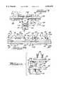
- FIG. 8is a fragmentary side view of an apparatus for the external fixation of bone according to the teachings of a second preferred embodiment of the present invention.
- FIG. 9is a cross-sectional view taken along the line 9--9 of FIG. 8;
- FIG. 10is a cross-sectional view taken along the line 10--10 of FIG. 8;
- FIG. 11is an exploded view of the second bone screw clamping assembly shown in FIG. 8 according to the teachings of the second preferred embodiment of the present invention.
- FIG. 12is a top view of a driven element shown in FIG. 8 according to the teachings of the second preferred embodiment of the present invention.
- FIG. 13is a fragmentary top view of an apparatus for the external fixation of bone according to the teachings of the second preferred embodiment of the present invention, illustrating a second orientation of the second bone screw clamping assembly in phantom lines.
- FIGS. 1-7an apparatus 10 for the external fixation of a bone 12 is shown.
- the apparatus 10is shown connected to the bone 12 through a plurality of bone screws 14a and 14b which serve to secure a first bone portion 12a relative to a second bone portion 12b.
- the first and second bone portions 12a and 12b secured by the apparatus 10are of a single bone 12.
- the bone 12 shown in the drawingsrepresents a human tibia. It is to be understood, however, that the apparatus 10 may be operatively attached to a variety of other types of bones and used to correct bone deformities, corrected malunions, or repair fractures.
- the orientation of the first portion 12a relative to the second portion 12bmay be angularly adjusted.
- the apparatus 10comprises a first bone screw clamping assembly 20 and a second bone screw clamping assembly 22.
- the first bone screw clamping assembly 20is used to secure a first bone screw 14a to the apparatus 10 while permitting the first bone screw 14a to be axially displaced from the second bone screw 14b.
- the first bone screw clamping assembly 20includes a main body having a base portion 24 and a cover portion 26.
- the base portion 24serves to receive the first bone screw 14a in one of a plurality of grooves 28, while the cover portion 26 serves to secure the first bone screw 14a within the groove 28.
- the grooves 28include two contact surfaces which are substantially planar so as to permit line contact of the first bone screw 14a in two positions within the grooves 28. Since the first bone screw 14a also engages the cover portion 26 of the first bone screw clamping assembly 20, the first bone screw 14a engages the first bone screw clamping assembly 20 in three positions (i.e., along the contact surfaces of the grooves 28 as well as on the cover portion 26). This provides line contact for the bone screw 14 which secures the bone screws 14 in a more effective manner than if the grooves 28 were cylindrical.
- the base portion 24 of the bone screw clamping assembly 20further includes a first aperture 34 and a second aperture 36.
- the first aperture 34is used to receive a threaded fastener 38 (shown in phantom in FIG. 2) which serves to secure a rail member 40 in a locked position as will be more fully discussed below.
- the second aperture 36is also used to receive a threaded member (not shown) which is able to secure a compression/distraction member (not shown).
- One suitable compression/distraction memberis described in connection with the external fixator disclosed in U.S. Pat. No. 5,662,650.
- the cover portion 26 of the first bone screw clamping assembly 20is secured to the base portion 24 of the first bone screw clamping assembly 20 by means of two screws 42.
- the cover portion 26 of the bone screw clamping assembly 20includes two apertures 44 (shown in phantom in FIGS. 2 and 4a) which mate with corresponding apertures 46 in the base portion 24 of the bone screw clamping assembly 20. Accordingly, upon secured threaded engagement of the screws 42 within the apertures 44 and 46, the cover portion 26 of the bone screw clamping assembly 20 may be secured to the base portion 24 of the bone screw clamping assembly 20.
- the bone screw clamping assembly 20further includes a first rail member 40.
- the rail member 40includes a D-shaped extension 48 which is able to be received in a D-shaped bore 50 of the bone screw clamping assembly 20.
- the D-shaped extension 48includes an elongated slot 51 for receiving the fastener 38. Because of the cross-sectional shape of the D-shaped extension 48, the base portion 24 of the bone screw clamping assembly 20 is able to slide on the extension 48 of the rail member 40. However, the base portion 24 is unable to rotate with respect to the D-shaped extension 48.
- the apparatus 10is illustrated to include a connection member 60.
- the connection member 60serves to secure the first and second bone screw clamping assemblies 20 and 22.
- a plurality of grooved locking washers 62are disposed between the rail member 40 and the connection member 60.
- the rail member 40has an aperture 64 with a hex-shaped recess 66 for receiving the base portion 68 of the washer 62.
- the connection member 60also includes an aperture 70 (shown in phantom in FIG. 2) with a hex-shaped recess 72 (shown in phantom in FIG. 2) for receiving the base portion 68 of the washer 62. Because a groove surface 74 of each of the washers 62 engage each other, the connector member 60 is secured to the first bone clamping assembly 20 upon secured threaded engagement of a screw 76.
- the second bone screw clamping assembly 22is operable to secure a second bone screw 14b to the apparatus 10.
- the second bone screw clamping assembly 22is preferably operable to secure a plurality of bone screws 14b to the apparatus 10.
- the second bone screw clamping assembly 22includes a main body 80.
- the main body 80is shown to be preferably arcuate in shape and defines a pair of arcuate recesses 82 passing therethrough.
- the arcuate recessesare operable for adjustably securing the bone screws 14b to the main body 80.
- each of the bone screws 14bis held adjacent to the main body 80 with a retainer member 84.
- Each of the retainer members 84defines a channel 86 for receiving one of the bone screws 14b.
- Each retainer member 84is further formed to include an internally threaded aperture 88 for receiving a fastener 90.
- the fastener 90passes through one of the arcuate slots 82 and includes a head 92 which can be tightened against the opposite side of the main body 80.
- the arcuate configuration of the main body 80allows the bone screws 14b of the plurality of the bone screws to converge upon the second portion 12b of the bone 12.
- the second clamping assembly 22is shown to be pivotally attached to the connection member 60 through a pivot pin 96.
- the pivot pin 96defines a pivot axis which is substantially perpendicular to the pivot axis defined by the screw 76 which interconnects the connection member 60 and the first bone screw clamping assembly 20.
- pivotal attachment of the second bone screw clamping assembly 22 and the connection member 60permit the second bone screw clamping assembly 22 to rotate from a neutral position (shown in solid lines) , clockwise (shown in phantom lines), or counterclockwise (not shown) through approximately 30°.
- the connection member 60thus permits approximately 60° of relative rotation between the first and second bone screw clamping assemblies 20 and 22.
- the apparatus 10is illustrated to include a drive unit 100.
- the drive unit 100is effectively a worm gear assembly including a driven element 102 and a drive element 104.
- the driven element 102is fixedly secured to the second bone screw clamping assembly 22 and includes an arcuate perimeter having a plurality of teeth 106.
- the drive element 104is rotatably retained within a transversely extending aperture 108 provided in the connection member 60 and includes a plurality of threads 110 operatively engage with the teeth 106 of the driven element 102.
- the drive element 104includes a head 112 having a hexagonal recess 114 (shown in phantom in FIG. 7) for receiving an hex wrench or similar tool for rotating the drive element 104.
- the drive element 104is rotatable about an axis substantially perpendicular to the pivot axis 96.
- the driven element 102rotates, for example, clockwise.
- the driven element 102is rotated counterclockwise, thereby angularly adjusting the second bone screw clamping assembly 22 and the bone screws 14b relative to the first bone screw clamping assembly 20 and the first bone screw 14a.
- the drive unit 100permits concise correlation between the number of rotations of the drive member 102 and the degrees of corrective angulation of the second bone screw clamping assembly 22.
- the nature of the drive unit 100eliminates the need for a locking mechanism. Therefore, gradual angulation over an extended period of time can be obtained without the nuisance of locking and unlocking a locking bolt.
- the apparatus 10 of the second embodiment of the present inventionincludes a first bone screw clamping assembly 20 and a second bone screw clamping assembly 22.
- the apparatus 10includes a longitudinally extending connection member 60 for interconnecting the first and second bone screw clamping assemblies 20 and 22.
- the first and second bone screw clamping assemblies 20 and 22 of the second preferred embodimentare operative to secure first and second bone screws 14a and 14b, respectively, to the apparatus 10.
- the first bone screw clamping assembly 20 of the second preferred embodimentincludes a cover 26 attached to a base 24 with a pair of threaded fasteners 42.
- the cover 26 and the base 24cooperates to define a plurality of openings 28 for receiving one or more bone screws 14a.
- the first and second bone screws 14a and 14blie in a common plane.
- both of the first and second bone screw clamping assemblies 20 and 22are adjustable along the connection member 60 in an axial or longitudinal direction indicated by double arrow A in FIG. 8.
- the base portion 24 of the first bone screw clamping assembly 20 of the second preferred embodimentis formed to define a pair of axially extending channels 120.
- the channels 120are adapted to slidably retain a pair of outwardly extending flanges 122 integrally formed with an upper surface of the connection member 60.
- the base portion 24is further formed to include an internally threaded aperture 124 (shown in phantom lines in FIG. 9) upwardly extending from a bottom side 126.
- the aperture 124is operable for receiving a fastener 128 as shown.
- the fastener 128includes a head 130 located within an axially extending channel 132 defined by the connection member 60 and a threaded shaft 134 which upwardly extends through an elongated slot 136 and engages the aperture 124.
- the threaded fastener 128further includes a mounting flange 138 operable to abut a lower surface 132 of the connection member 60.
- the mounting flange 138defines a hexagonal recess 140 (shown in phantom in FIG. 9) for receiving a hex wrench or similar tool.
- the second bone screw clamping assembly 22is similarly constructed to the first bone screw clamping assembly 20.
- the second bone screw clamping assembly 22is shown to include a base portion 24 and a cover portion 26.
- the base portion 26is adapted to axially translate relative to the connection member 60 in an identical manner.
- the apparatus 10 of the second preferred embodimentincludes a drive unit 100.
- the drive unit 100includes a driven element 102 which is fixedly secured to the cover 26 of the second bone screw clamping assembly 22.
- the driven element 102is a plate interdisposed between the cover 26 and the base 24.
- the plate 102is formed to include a pair of apertures 141 for receiving the fasteners 42.
- the plate 102is further formed to include a plurality of grooves 28 for receiving the second bone screws 14b.
- the cover portion 26cooperates with the grooves 28 to maintain the bone screws 14b.
- the plate 102is pivotally interconnected to the base 24 through a pin 142.
- the pin 142engages an aperture 144 in the plate and an aperture 146 in the base portion 24.
- the plate 102serves to define a pivot axis.
- the drive element 104is rotatably retained within a transversely extending aperture 148 provided in an upwardly extending rectangular portion 150 which is integrally formed with the base 24.
- the drive element 104includes a plurality of threads 152 operatively engaged with a plurality of teeth 154 formed on an arcuate perimeter of the driven member 102.
- the drive element 104includes a head 112 having a hexagonal recess 114 for receiving a hex wrench or other similar tool for rotating the drive element 104.
- the drive element 104is rotatably about an axis substantially perpendicular to the pivot axis defined by the pin 142.
- the driven element 102rotates, for example, clockwise.
- the driven element 102is rotated counterclockwise.
- the bone screw 14a of the first bone screw clamping assembly 20is angularly adjusted relative to the bone screw 14b of the second bone screw clamping assembly 22.
Landscapes
- Health & Medical Sciences (AREA)
- Orthopedic Medicine & Surgery (AREA)
- Life Sciences & Earth Sciences (AREA)
- Surgery (AREA)
- Biomedical Technology (AREA)
- Engineering & Computer Science (AREA)
- Nuclear Medicine, Radiotherapy & Molecular Imaging (AREA)
- Heart & Thoracic Surgery (AREA)
- Medical Informatics (AREA)
- Molecular Biology (AREA)
- Animal Behavior & Ethology (AREA)
- General Health & Medical Sciences (AREA)
- Public Health (AREA)
- Veterinary Medicine (AREA)
- Surgical Instruments (AREA)
Abstract
Description
Claims (16)
Priority Applications (3)
| Application Number | Priority Date | Filing Date | Title |
|---|---|---|---|
| US08/972,524US5941879A (en) | 1997-11-18 | 1997-11-18 | Method and apparatus for external fixation of bones |
| AU15937/99AAU1593799A (en) | 1997-11-18 | 1998-11-18 | Method and apparatus for external fixation of bones |
| PCT/US1998/024768WO1999025264A1 (en) | 1997-11-18 | 1998-11-18 | Method and apparatus for external fixation of bones |
Applications Claiming Priority (1)
| Application Number | Priority Date | Filing Date | Title |
|---|---|---|---|
| US08/972,524US5941879A (en) | 1997-11-18 | 1997-11-18 | Method and apparatus for external fixation of bones |
Publications (1)
| Publication Number | Publication Date |
|---|---|
| US5941879Atrue US5941879A (en) | 1999-08-24 |
Family
ID=25519757
Family Applications (1)
| Application Number | Title | Priority Date | Filing Date |
|---|---|---|---|
| US08/972,524Expired - Fee RelatedUS5941879A (en) | 1997-11-18 | 1997-11-18 | Method and apparatus for external fixation of bones |
Country Status (3)
| Country | Link |
|---|---|
| US (1) | US5941879A (en) |
| AU (1) | AU1593799A (en) |
| WO (1) | WO1999025264A1 (en) |
Cited By (15)
| Publication number | Priority date | Publication date | Assignee | Title |
|---|---|---|---|---|
| US6136037A (en)* | 1997-02-03 | 2000-10-24 | Intraplant Ag | Implant delivery device in the treatment of trochanter and subtrochanter fractures |
| US6423061B1 (en) | 2000-03-14 | 2002-07-23 | Amei Technologies Inc. | High tibial osteotomy method and apparatus |
| US20030069580A1 (en)* | 2001-10-09 | 2003-04-10 | Langmaid Michael N. | Adjustable fixator |
| US6565564B2 (en) | 2000-12-14 | 2003-05-20 | Synthes U.S.A. | Multi-pin clamp and rod attachment |
| US6678562B1 (en) | 2000-01-12 | 2004-01-13 | Amei Technologies Inc. | Combined tissue/bone growth stimulator and external fixation device |
| US20040059331A1 (en)* | 2002-09-17 | 2004-03-25 | Visionmed, L.L.C. | Unilateral fixator |
| US20040097922A1 (en)* | 2002-11-14 | 2004-05-20 | Visionmed, L.L.C. | Method for a using fixator device |
| US20080161816A1 (en)* | 2002-12-04 | 2008-07-03 | Peter M. Stevens | Bone alignment implant and method of use |
| US20080221571A1 (en)* | 2007-03-07 | 2008-09-11 | Aaron Daluiski | External Fixation |
| US20100100096A1 (en)* | 2005-03-07 | 2010-04-22 | Wright Medical Technology, Inc. | External fixator |
| US7780706B2 (en) | 2005-04-27 | 2010-08-24 | Trinity Orthopedics, Llc | Mono-planar pedicle screw method, system and kit |
| US20110172664A1 (en)* | 2008-09-16 | 2011-07-14 | Orthofix S.R.L. | Orthopaedic device for correcting deformities of long bones |
| US8758343B2 (en) | 2005-04-27 | 2014-06-24 | DePuy Synthes Products, LLC | Bone fixation apparatus |
| US9408635B2 (en) | 2013-03-15 | 2016-08-09 | Wright Medical Technology, Inc. | External fixation |
| US12433641B2 (en) | 2023-09-20 | 2025-10-07 | Şehmuz Işin | Unilateral external fixator apparatus and control method |
Families Citing this family (22)
| Publication number | Priority date | Publication date | Assignee | Title |
|---|---|---|---|---|
| EP1079751B1 (en) | 1998-05-19 | 2007-02-28 | Synthes GmbH | Cheek for a one-sided external fixation system for traumatology and orthopedics |
| DE10129942B4 (en)* | 2000-06-16 | 2007-08-02 | Veith, Wolfgang, Dr. | Angle adjusting device for a bone fixator |
| RU2299033C2 (en)* | 2005-05-30 | 2007-05-20 | Дагестанская государственная медицинская академия | Apparatus for urgent out-of-site osteosynthesis of shin fractures |
| RU2307614C2 (en)* | 2005-08-09 | 2007-10-10 | Дагестанская государственная медицинская академия | Device for repositioning bone fractures when treating breaks of long bones of lower extremities by means of skeletal extension |
| RU2328242C2 (en)* | 2005-08-15 | 2008-07-10 | ГУ Научный Центр реконструктивной и восстановительной хирургии ВСНЦ СО РАМН (ГУ НЦ РВХ ВСНЦ СО РАМН) | Method of transosseous osteosynthesis of disphysial forearm damages and related device |
| US7708736B2 (en) | 2006-02-22 | 2010-05-04 | Extraortho, Inc. | Articulation apparatus for external fixation device |
| RU2324448C2 (en)* | 2006-02-26 | 2008-05-20 | ГУ Научный Центр реконструктивной и восстановительной хирургии ВСНЦ СО РАМН (ГУ НЦ РВХ ВСНЦ СО РАМН) | Method of transosseous ostheosynthesis of monteggia fracture-disclocation of forearm bones and device |
| RU2325866C1 (en)* | 2006-10-09 | 2008-06-10 | Джевдет Энвербекович Купкенов | Device for reposition and fixation of fractures of anticnemion bones |
| RU2327431C1 (en)* | 2006-12-26 | 2008-06-27 | Джевдет Энвербекович Купкенов | Apparatus for reduction and fixation of leg fracture |
| EP2197372B1 (en) | 2007-09-27 | 2016-04-13 | Zimmer, Inc. | Clamping apparatus for external fixation and stabilization |
| RU2352284C1 (en)* | 2007-10-25 | 2009-04-20 | Владимир Николаевич Ребров | Device for treatment of difficult fractures of radial bone |
| RU2353321C1 (en)* | 2007-10-25 | 2009-04-27 | Владимир Николаевич Ребров | Spoke bone fracture treatment apparatus |
| US9138260B2 (en) | 2010-07-01 | 2015-09-22 | Zimmer, Inc. | Multi-locking external fixation clamp |
| WO2012051255A1 (en) | 2010-10-12 | 2012-04-19 | Extraortho, Inc. | External fixation surgical clamp with swivel |
| WO2012051312A1 (en) | 2010-10-12 | 2012-04-19 | Extraortho, Inc. | Single lock external fixation clamp arrangement |
| US8728078B2 (en) | 2010-11-04 | 2014-05-20 | Zimmer, Inc. | Clamping assembly with links |
| WO2012078897A1 (en) | 2010-12-09 | 2012-06-14 | Extraortho, Inc. | Revolving lock for external fixation clamps |
| EP2648633B1 (en) | 2010-12-09 | 2016-05-18 | Zimmer, Inc. | External fixation clamp with cam driven jaw |
| JP6106662B2 (en) | 2011-05-17 | 2017-04-05 | ジンマー,インコーポレイティド | External fixed clamping system using a starting mechanism and stored spring energy |
| RU2463989C1 (en)* | 2011-06-27 | 2012-10-20 | Государственное образовательное учреждение высшего профессионального образования "Дагестанская государственная медицинская академия федерального агентства по здравоохранению и социальному развитию" | Device for closed reposition of sagging tibial condyle |
| RU171316U1 (en)* | 2016-11-17 | 2017-05-29 | Федеральное государственное бюджетное образовательное учреждение высшего образования "Забайкальский государственный университет" (ФГБОУ ВО "ЗабГУ") | DEVICE FOR POSITIONING AND INSTALLING THE TENDON TRANSPLANT FOR PREPARATION |
| EP3698742A1 (en)* | 2019-02-19 | 2020-08-26 | Arthrex Inc | Alignment device for bones |
Citations (13)
| Publication number | Priority date | Publication date | Assignee | Title |
|---|---|---|---|---|
| US4615338A (en)* | 1985-09-18 | 1986-10-07 | Kurgansky Nauchno-Issledovatelsky Institut Experimentalnoi I Klinicheskoi Ortopedii I Travmatologii | Automatic compression-distraction apparatus |
| US4784125A (en)* | 1985-01-24 | 1988-11-15 | Jaquet Orthopedie, S. A. | Arcuate element and external fixation device containing same for osteosynthesis and osteoplasty |
| US4895141A (en)* | 1984-04-26 | 1990-01-23 | Harrington Arthritis Research Center | Unilateral external fixation device |
| US4978347A (en)* | 1988-07-26 | 1990-12-18 | Ilizarov Gavrill A | Distraction apparatus for osteosynthesis of short tubular bones |
| US4978348A (en)* | 1988-05-26 | 1990-12-18 | Ilizarov Gavriil A | Compression-distraction apparatus for osteosynthesis |
| US5074866A (en)* | 1990-10-16 | 1991-12-24 | Smith & Nephew Richards Inc. | Translation/rotation device for external bone fixation system |
| US5376091A (en)* | 1990-06-08 | 1994-12-27 | Smith & Nephew Richards, Inc. | Dynamic finger support |
| US5380322A (en)* | 1991-06-18 | 1995-01-10 | Van Den Brink; Breunis | Bone fixation device |
| US5437667A (en)* | 1992-11-10 | 1995-08-01 | Innovative Orthopaedics, Manufacturing, Inc. | Dynamic external fixator for the wrist |
| US5486176A (en)* | 1991-03-27 | 1996-01-23 | Smith & Nephew Richards, Inc. | Angled bone fixation apparatus |
| US5620442A (en)* | 1995-05-12 | 1997-04-15 | Bailey; Kirk J. | Method and apparatus for external fixation of small bones |
| US5662650A (en)* | 1995-05-12 | 1997-09-02 | Electro-Biology, Inc. | Method and apparatus for external fixation of large bones |
| US5803924A (en)* | 1993-08-05 | 1998-09-08 | Hi-Shear Fastners Europe Limited | External fixator |
- 1997
- 1997-11-18USUS08/972,524patent/US5941879A/ennot_activeExpired - Fee Related
- 1998
- 1998-11-18WOPCT/US1998/024768patent/WO1999025264A1/enactiveApplication Filing
- 1998-11-18AUAU15937/99Apatent/AU1593799A/ennot_activeAbandoned
Patent Citations (14)
| Publication number | Priority date | Publication date | Assignee | Title |
|---|---|---|---|---|
| US4895141A (en)* | 1984-04-26 | 1990-01-23 | Harrington Arthritis Research Center | Unilateral external fixation device |
| US5095919A (en)* | 1985-01-24 | 1992-03-17 | Jaquet Orthopedie S.A. | Arcuate element and external fixation device |
| US4784125A (en)* | 1985-01-24 | 1988-11-15 | Jaquet Orthopedie, S. A. | Arcuate element and external fixation device containing same for osteosynthesis and osteoplasty |
| US4615338A (en)* | 1985-09-18 | 1986-10-07 | Kurgansky Nauchno-Issledovatelsky Institut Experimentalnoi I Klinicheskoi Ortopedii I Travmatologii | Automatic compression-distraction apparatus |
| US4978348A (en)* | 1988-05-26 | 1990-12-18 | Ilizarov Gavriil A | Compression-distraction apparatus for osteosynthesis |
| US4978347A (en)* | 1988-07-26 | 1990-12-18 | Ilizarov Gavrill A | Distraction apparatus for osteosynthesis of short tubular bones |
| US5376091A (en)* | 1990-06-08 | 1994-12-27 | Smith & Nephew Richards, Inc. | Dynamic finger support |
| US5074866A (en)* | 1990-10-16 | 1991-12-24 | Smith & Nephew Richards Inc. | Translation/rotation device for external bone fixation system |
| US5486176A (en)* | 1991-03-27 | 1996-01-23 | Smith & Nephew Richards, Inc. | Angled bone fixation apparatus |
| US5380322A (en)* | 1991-06-18 | 1995-01-10 | Van Den Brink; Breunis | Bone fixation device |
| US5437667A (en)* | 1992-11-10 | 1995-08-01 | Innovative Orthopaedics, Manufacturing, Inc. | Dynamic external fixator for the wrist |
| US5803924A (en)* | 1993-08-05 | 1998-09-08 | Hi-Shear Fastners Europe Limited | External fixator |
| US5620442A (en)* | 1995-05-12 | 1997-04-15 | Bailey; Kirk J. | Method and apparatus for external fixation of small bones |
| US5662650A (en)* | 1995-05-12 | 1997-09-02 | Electro-Biology, Inc. | Method and apparatus for external fixation of large bones |
Non-Patent Citations (4)
| Title |
|---|
| EBI Medical Systems brochure entitled "Orthofix® Modulsystem", 61 numbered pages (dated Apr. 1993). |
| EBI Medical Systems brochure entitled ORTHOFIX® Modulsystem , 61 numbered pag es (dated Apr. 1993).* |
| Undated brochure describing Of Garche Limb Lengther, 12 pages.* |
| Undated brochure describing Of-Garche Limb Lengther, 12 pages. |
Cited By (34)
| Publication number | Priority date | Publication date | Assignee | Title |
|---|---|---|---|---|
| US6136037A (en)* | 1997-02-03 | 2000-10-24 | Intraplant Ag | Implant delivery device in the treatment of trochanter and subtrochanter fractures |
| US6678562B1 (en) | 2000-01-12 | 2004-01-13 | Amei Technologies Inc. | Combined tissue/bone growth stimulator and external fixation device |
| US6423061B1 (en) | 2000-03-14 | 2002-07-23 | Amei Technologies Inc. | High tibial osteotomy method and apparatus |
| US6565564B2 (en) | 2000-12-14 | 2003-05-20 | Synthes U.S.A. | Multi-pin clamp and rod attachment |
| US20030191468A1 (en)* | 2000-12-14 | 2003-10-09 | Synthes U.S.A. | Multipin clamp and rod attachment |
| US20030191467A1 (en)* | 2000-12-14 | 2003-10-09 | Hoffmann-Clair Mindy L. | Multipin clamp and rod attachment |
| US7699848B2 (en) | 2000-12-14 | 2010-04-20 | Synthes Usa, Llc | Multipin clamp and rod attachment |
| US7041103B2 (en) | 2000-12-14 | 2006-05-09 | Synthes (Usa) | Multipin clamp and rod attachment |
| US20030069580A1 (en)* | 2001-10-09 | 2003-04-10 | Langmaid Michael N. | Adjustable fixator |
| US7261713B2 (en) | 2001-10-09 | 2007-08-28 | Synthes (Usa) | Adjustable fixator |
| US8382757B1 (en) | 2001-10-09 | 2013-02-26 | Synthes Usa, Llc | Adjustable fixator |
| US20040059331A1 (en)* | 2002-09-17 | 2004-03-25 | Visionmed, L.L.C. | Unilateral fixator |
| US7282052B2 (en) | 2002-09-17 | 2007-10-16 | Ebi, L.P. | Unilateral fixator |
| US20070282338A1 (en)* | 2002-09-17 | 2007-12-06 | Ebi, L.P. | Unilateral fixator |
| US8388619B2 (en) | 2002-09-17 | 2013-03-05 | Sixfix Inc. | Unilateral fixator |
| US20040097922A1 (en)* | 2002-11-14 | 2004-05-20 | Visionmed, L.L.C. | Method for a using fixator device |
| US20110103676A1 (en)* | 2002-11-14 | 2011-05-05 | Extraortho, Inc. | Method for using a fixator device |
| US8419732B2 (en) | 2002-11-14 | 2013-04-16 | Sixfix, Inc. | Method for using a fixator device |
| US20080161816A1 (en)* | 2002-12-04 | 2008-07-03 | Peter M. Stevens | Bone alignment implant and method of use |
| US8133230B2 (en)* | 2002-12-04 | 2012-03-13 | Peter M. Stevens | Bone alignment implant and method of use |
| US8808291B2 (en) | 2005-03-07 | 2014-08-19 | Wright Medical Technology, Inc. | External fixator |
| US20100100096A1 (en)* | 2005-03-07 | 2010-04-22 | Wright Medical Technology, Inc. | External fixator |
| US8235994B2 (en) | 2005-03-07 | 2012-08-07 | Wright Medical Technology, Inc. | External fixator |
| US8486069B2 (en) | 2005-03-07 | 2013-07-16 | Wright Medical Technology, Inc. | External fixator |
| US8758343B2 (en) | 2005-04-27 | 2014-06-24 | DePuy Synthes Products, LLC | Bone fixation apparatus |
| US8298268B2 (en) | 2005-04-27 | 2012-10-30 | Trinty Orthopedics, LLC. | Mono-planar pedicle screw method, system and kit |
| US7780706B2 (en) | 2005-04-27 | 2010-08-24 | Trinity Orthopedics, Llc | Mono-planar pedicle screw method, system and kit |
| US20080221571A1 (en)* | 2007-03-07 | 2008-09-11 | Aaron Daluiski | External Fixation |
| US8277448B2 (en) | 2007-03-07 | 2012-10-02 | Wright Medical Technology, Inc. | External fixation |
| US20110172664A1 (en)* | 2008-09-16 | 2011-07-14 | Orthofix S.R.L. | Orthopaedic device for correcting deformities of long bones |
| US8951253B2 (en)* | 2008-09-16 | 2015-02-10 | Orthofix S.R.L. | Orthopaedic device for correcting deformities of long bones |
| US9592080B2 (en) | 2008-09-16 | 2017-03-14 | Orthofix S.R.L. | Orthopaedic device for correcting deformities of long bones |
| US9408635B2 (en) | 2013-03-15 | 2016-08-09 | Wright Medical Technology, Inc. | External fixation |
| US12433641B2 (en) | 2023-09-20 | 2025-10-07 | Şehmuz Işin | Unilateral external fixator apparatus and control method |
Also Published As
| Publication number | Publication date |
|---|---|
| WO1999025264A1 (en) | 1999-05-27 |
| AU1593799A (en) | 1999-06-07 |
Similar Documents
| Publication | Publication Date | Title |
|---|---|---|
| US5941879A (en) | Method and apparatus for external fixation of bones | |
| US6277118B1 (en) | External fixator including an angular correction module and related method | |
| US7449023B2 (en) | Method and apparatus for the external fixation and correction of bone | |
| US6010501A (en) | Method and apparatus for external fixation of small bones | |
| US5976136A (en) | Method and apparatus for external bone fixator | |
| US6171308B1 (en) | Method and apparatus for external fixation of large bones | |
| US5743898A (en) | Method and apparatus for external fixation of small bones | |
| US4922896A (en) | Colles' fracture splint | |
| EP1229846B1 (en) | External fixation system | |
| US5681309A (en) | Distractor mechanism for external fixation device | |
| US5304177A (en) | Auxiliary device for osteosynthesis | |
| EP1434531B1 (en) | Adjustable fixator | |
| US6152925A (en) | Method and apparatus for external fixation of an elbow | |
| US5620442A (en) | Method and apparatus for external fixation of small bones | |
| EP0425783B1 (en) | Pedicle screw clamp | |
| US7341594B2 (en) | Surgical instrument for moving vertebrae | |
| US6616664B2 (en) | Clamp assembly for an external fixation system | |
| US6482206B2 (en) | Method and apparatus for external fixation of bones | |
| CA2208054A1 (en) | External fixator for distal radius fractures | |
| US20240261008A1 (en) | Apparatus for stablization of a bone fracture site | |
| US5203783A (en) | Osteosynthetic fixation and force transmitting apparatus | |
| EP3302322A1 (en) | Dynamic foot plate | |
| EP0904740A2 (en) | Implant with bone screw insert | |
| CN216777187U (en) | Angle-adjustable orthopedic external fixing device | |
| EP0801542B1 (en) | Device for osteosynthesis |
Legal Events
| Date | Code | Title | Description |
|---|---|---|---|
| CC | Certificate of correction | ||
| FPAY | Fee payment | Year of fee payment:4 | |
| FPAY | Fee payment | Year of fee payment:8 | |
| AS | Assignment | Owner name:ELECTRO-BIOLOGY, INC., NEW JERSEY Free format text:ASSIGNMENT OF ASSIGNORS INTEREST;ASSIGNORS:WALULIK, STEPHEN B.;BAILEY, KIRK J.;REEL/FRAME:019055/0146 Effective date:19971106 | |
| AS | Assignment | Owner name:EBI, L.P., NEW JERSEY Free format text:ASSIGNMENT OF ASSIGNORS INTEREST;ASSIGNOR:ELECTRO-BIOLOGY, INC.;REEL/FRAME:019287/0692 Effective date:20070515 | |
| AS | Assignment | Owner name:BANK OF AMERICA, N.A., AS ADMINISTRATIVE AGENT FOR Free format text:SECURITY AGREEMENT;ASSIGNORS:LVB ACQUISITION, INC.;BIOMET, INC.;REEL/FRAME:020362/0001 Effective date:20070925 | |
| AS | Assignment | Owner name:EBI, LLC, NEW JERSEY Free format text:CHANGE OF NAME;ASSIGNOR:EBI, INC.;REEL/FRAME:021387/0450 Effective date:20080227 Owner name:EBI, LLC,NEW JERSEY Free format text:CHANGE OF NAME;ASSIGNOR:EBI, INC.;REEL/FRAME:021387/0450 Effective date:20080227 | |
| AS | Assignment | Owner name:EBI, LLC, NEW JERSEY Free format text:CORRECTIVE ASSIGNMENT TO CORRECT THE ASSIGNOR INCORRECTLY IDENTIFIED AS EBI, INC. ON ORIGINAL RECORDATION COVERSHEET SHOULD HAVE BEEN IDENTIFIED AS EBI, L.P. PREVIOUSLY RECORDED ON REEL 021387 FRAME 0450;ASSIGNOR:EBI, L.P.;REEL/FRAME:022727/0859 Effective date:20080227 Owner name:EBI, LLC,NEW JERSEY Free format text:CORRECTIVE ASSIGNMENT TO CORRECT THE ASSIGNOR INCORRECTLY IDENTIFIED AS EBI, INC. ON ORIGINAL RECORDATION COVERSHEET SHOULD HAVE BEEN IDENTIFIED AS EBI, L.P. PREVIOUSLY RECORDED ON REEL 021387 FRAME 0450. ASSIGNOR(S) HEREBY CONFIRMS THE ORIGINAL CONVEYANCE TEXT APPEARING IN NAME CHANGE DOCUMENTATION REFLECTS EBI, L.P. IS NOW KNOWN AS EBI, LLC.;ASSIGNOR:EBI, L.P.;REEL/FRAME:022727/0859 Effective date:20080227 Owner name:EBI, LLC, NEW JERSEY Free format text:CORRECTIVE ASSIGNMENT TO CORRECT THE ASSIGNOR INCORRECTLY IDENTIFIED AS EBI, INC. ON ORIGINAL RECORDATION COVERSHEET SHOULD HAVE BEEN IDENTIFIED AS EBI, L.P. PREVIOUSLY RECORDED ON REEL 021387 FRAME 0450. ASSIGNOR(S) HEREBY CONFIRMS THE ORIGINAL CONVEYANCE TEXT APPEARING IN NAME CHANGE DOCUMENTATION REFLECTS EBI, L.P. IS NOW KNOWN AS EBI, LLC.;ASSIGNOR:EBI, L.P.;REEL/FRAME:022727/0859 Effective date:20080227 | |
| REMI | Maintenance fee reminder mailed | ||
| LAPS | Lapse for failure to pay maintenance fees | ||
| STCH | Information on status: patent discontinuation | Free format text:PATENT EXPIRED DUE TO NONPAYMENT OF MAINTENANCE FEES UNDER 37 CFR 1.362 | |
| FP | Lapsed due to failure to pay maintenance fee | Effective date:20110824 | |
| AS | Assignment | Owner name:BIOMET, INC., INDIANA Free format text:RELEASE OF SECURITY INTEREST IN PATENTS RECORDED AT REEL 020362/ FRAME 0001;ASSIGNOR:BANK OF AMERICA, N.A., AS ADMINISTRATIVE AGENT;REEL/FRAME:037155/0133 Effective date:20150624 Owner name:LVB ACQUISITION, INC., INDIANA Free format text:RELEASE OF SECURITY INTEREST IN PATENTS RECORDED AT REEL 020362/ FRAME 0001;ASSIGNOR:BANK OF AMERICA, N.A., AS ADMINISTRATIVE AGENT;REEL/FRAME:037155/0133 Effective date:20150624 |