US5941182A - Self-braking height adjustment mechanism - Google Patents
Self-braking height adjustment mechanismDownload PDFInfo
- Publication number
- US5941182A US5941182AUS08/865,360US86536097AUS5941182AUS 5941182 AUS5941182 AUS 5941182AUS 86536097 AUS86536097 AUS 86536097AUS 5941182 AUS5941182 AUS 5941182A
- Authority
- US
- United States
- Prior art keywords
- ball screw
- work surface
- adjustment mechanism
- rotated
- movable portion
- Prior art date
- Legal status (The legal status is an assumption and is not a legal conclusion. Google has not performed a legal analysis and makes no representation as to the accuracy of the status listed.)
- Expired - Lifetime
Links
- 230000007246mechanismEffects0.000titleclaimsabstractdescription116
- DHKHKXVYLBGOIT-UHFFFAOYSA-Nacetaldehyde Diethyl AcetalNatural productsCCOC(C)OCCDHKHKXVYLBGOIT-UHFFFAOYSA-N0.000claimsdescription2
- 125000002777acetyl groupChemical class[H]C([H])([H])C(*)=O0.000claims1
- 230000013011matingEffects0.000abstractdescription2
- 239000000463materialSubstances0.000description8
- 230000006835compressionEffects0.000description6
- 238000007906compressionMethods0.000description6
- 230000000712assemblyEffects0.000description5
- 238000000429assemblyMethods0.000description5
- 238000006243chemical reactionMethods0.000description3
- NJPPVKZQTLUDBO-UHFFFAOYSA-NnovaluronChemical compoundC1=C(Cl)C(OC(F)(F)C(OC(F)(F)F)F)=CC=C1NC(=O)NC(=O)C1=C(F)C=CC=C1FNJPPVKZQTLUDBO-UHFFFAOYSA-N0.000description3
- 229920004943Delrin®Polymers0.000description2
- 230000008859changeEffects0.000description2
- 229920002635polyurethanePolymers0.000description2
- 239000004814polyurethaneSubstances0.000description2
- 229910000831SteelInorganic materials0.000description1
- 239000011354acetal resinSubstances0.000description1
- 230000004075alterationEffects0.000description1
- 230000008878couplingEffects0.000description1
- 238000010168coupling processMethods0.000description1
- 238000005859coupling reactionMethods0.000description1
- 230000005484gravityEffects0.000description1
- 238000012986modificationMethods0.000description1
- 230000004048modificationEffects0.000description1
- 229920003023plasticPolymers0.000description1
- 239000004033plasticSubstances0.000description1
- 229920006324polyoxymethylenePolymers0.000description1
- 230000000284resting effectEffects0.000description1
- 238000005096rolling processMethods0.000description1
- 230000003068static effectEffects0.000description1
- 239000010959steelSubstances0.000description1
Images


Classifications
- A—HUMAN NECESSITIES
- A47—FURNITURE; DOMESTIC ARTICLES OR APPLIANCES; COFFEE MILLS; SPICE MILLS; SUCTION CLEANERS IN GENERAL
- A47B—TABLES; DESKS; OFFICE FURNITURE; CABINETS; DRAWERS; GENERAL DETAILS OF FURNITURE
- A47B9/00—Tables with tops of variable height
- A47B9/12—Tables with tops of variable height with flexible height-adjusting means, e.g. rope, chain
- A—HUMAN NECESSITIES
- A47—FURNITURE; DOMESTIC ARTICLES OR APPLIANCES; COFFEE MILLS; SPICE MILLS; SUCTION CLEANERS IN GENERAL
- A47B—TABLES; DESKS; OFFICE FURNITURE; CABINETS; DRAWERS; GENERAL DETAILS OF FURNITURE
- A47B2200/00—General construction of tables or desks
- A47B2200/0011—Underframes
- A47B2200/002—Legs
- A47B2200/0026—Desks with C-shaped leg
- A—HUMAN NECESSITIES
- A47—FURNITURE; DOMESTIC ARTICLES OR APPLIANCES; COFFEE MILLS; SPICE MILLS; SUCTION CLEANERS IN GENERAL
- A47B—TABLES; DESKS; OFFICE FURNITURE; CABINETS; DRAWERS; GENERAL DETAILS OF FURNITURE
- A47B9/00—Tables with tops of variable height
- A47B9/02—Tables with tops of variable height with balancing device, e.g. by springs, by weight
Definitions
- This inventionrelates to a self-braking height adjustment mechanism, and more particularly to a self-braking vertical adjustment mechanism for a table or workstation that can be easily adjusted relative to the weight being supported by the table or workstation.
- Furniture componentssuch as computer workstations or the like, have various types of height adjustment mechanisms. These surfaces, while supporting heavy equipment such as computer monitors, terminals and various other desk accessories, are desired to be vertically adjustable so as to accommodate a variety of tasks or a variety of users easily and comfortably. Examples of such adjustable workstations are U.S. Pat. Nos. 5,598,788 and 5,598,789, both assigned to the present assignee and incorporated herein by reference.
- these adjustable mechanismsallow the tabletop to be adjusted upwardly or downwardly to accommodate the different user or task.
- Various meanssuch as springs, pulley arrangements, worm-gear, screw arrangements or counterbalancing weights are used to provide relatively effortless raising and lowering of the table surface.
- One common type of height adjustment mechanismis a screw arrangement wherein a hand crank is used to rotate a screw mechanism which causes the table surface to either rise or lower according to the wishes of the user.
- One problem associated with these types of hand crank mechanismsis that excessive torque may be required on the crank to lift heavier loads, such as on the order of 250 to 300 pounds, particularly when a desirable lift rate is one inch of lift for every four or five turns of the crank handle. This is commonly accomplished by the use of an Acme thread screw in either one or both sides of the table base and to synchronize the left and right sides with a sprocket and chain assembly or other means.
- a more efficient way to convert a cranking torque to a lifting forceis to use an efficient rotational interface such as a ball thread assembly consisting of a ball screw and a ball nut.
- a ball thread assemblyrepresents an efficient rotational interface since rolling and not sliding is the torque to force conversion mechanism.
- this type of an arrangement95% or more of the cranking torque is converted to lifting force, thus cranking torque is kept to a minimum.
- this mechanismmay not adequately maintain the lifted load in a desired position; that is, backwinding of the ball screw and lowering of the work table may occur. The use of a brake or lock to prevent backwinding thus becomes necessary.
- U.S. Pat. No. 3,385,238 issued to Jayis an example of such an arrangement.
- the braking mechanismmust not lessen the efficiency of the ball screw assembly in the lifting direction, which would require greater cranking force for a given load. It must not inadvertently disengage at any time since that may present the user with a sudden, uncontrollable burst of torque in either the lifting or lowering directions.
- the magnitude of the lowering torquebe similar to that required for the raising torque; and as the cranking torque in the lift direction will increase with additional loading, so should the lowering torque so that the operator is unaware of the automatic braking provided by the lift mechanism.
- a hand crank mechanismis a simple and effective means of applying the cranking torque to the ball thread assembly.
- a handle which is gripped and rotated by the useris connected through a suitable linkage mechanism to the ball screw. While it is desirable that the handle be easily accessible by the operator, it is also advantageous that the handle not obstruct either the work surface, or the area under the desk in which orientation of the handle may be inadvertently bumped by the user, causing both discomfort to the user as well as unintended operation of the height adjustment mechanism.
- a removable handlewould solve this problem, it has the potential to result in loss or misplacement which prevents adjustment of the work surface.
- the vertically adjustable workstation of the present inventionwhich comprises a work surface connected to a base.
- the baseincludes a movable portion and a stationary portion, the work surface being connected to the movable portion.
- the movable portionincludes a vertical adjustment mechanism having an automatic braking mechanism for locking the work surface in a vertical position.
- the vertical adjustment mechanismcomprises a rotational member.
- This rotational membermost preferably comprises a vertically movable ball screw which threadingly engages a ball nut which is rigidly secured to the leg portion.
- the ball screwis rotated by a handle crank so as to move the ball screw up and down with respect to the leg.
- the automatic brake assemblypreferably comprises a clutch mechanism which is secured to the ball screw.
- the clutch mechanismis comprised of a roller clutch, pressed into an outer sleeve, which is fixed to a friction cap.
- a thrust needle bearingis disposed between the roller clutch and the ball screw.
- the work surfaceprovides a non-rotation friction surface.
- the clutch mechanismallows for free rotation of the ball screw within the clutch during upward translation of the work surface, while the clutch mechanism engages the ball screw and rotates therewith when the ball screw is rotated in a downward direction.
- This feature, along with the disposition of the elementsallows the rotation-thrust interface to occur within the thrust needle bearing while lifting, but forces this interface to occur between the non-rotating friction surface and friction cap while at rest or lowering; thus preventing backwinding. Since the load on the work surface is being carried by the screw, and through the friction surfaces, any change in load results in a relative change in the friction force, thus the (automatic) self-adjustment feature is provided.
- a collapsible handle assemblyis provided.
- the handleremains attached to the table and is pivotally connected to the shaft.
- the handlecan be locked in either an operating position or a collapsed position.
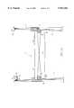
- FIG. 1is a perspective view of a height adjustable table in accordance with the present invention
- FIG. 2consisting of FIGS. 2A and 2B, shows a side elevational view of the adjustable height table leg with the cover removed, FIG. 2A showing the leg in its lowermost position while FIG. 2B shows it in its uppermost position;
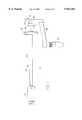
- FIG. 3is an exploded view of one leg of the adjustable table showing the self-braking height adjustment mechanism of the present invention shown therein;
- FIG. 4is a schematic representation of the brake assembly of the self-braking height adjustment mechanism of the present invention.
- FIG. 5,consisting of FIGS. 5A, 5B and 5C shows a preferred embodiment of the mechanism having a pulley arrangement used to level the adjustable table in the raising or lowering of the work surface;
- FIG. 6is an exploded view of a collapsible handle crank mechanism of the present invention.
- FIG. 7is a top view of the handle crank assembly in the collapsed position.
- FIG. 1shows a vertically adjustable table or workstation 20 in accordance with the present invention, which includes a base 22 comprising a pair of leg assemblies 23 supporting a work surface 26 in various positions relative to the floor or the user.
- Each leg assembly 23comprises a stationary portion 29 and a movable portion 32.
- the work surfaceis easily adjustable by the means of a crank handle 35.
- the crank handleis shown positioned on the left side of the table 20 in association with the left leg 23a, it is to be readily understood that the crank handle and the lift mechanism of the present invention could be incorporated in the right leg 23b.
- the work surfacecan be supported by a base assembly which comprises a pedestal or single leg.
- FIG. 2shows the work surface 26 in its lowermost (FIG. 2A) and its uppermost (FIG. 2B) positions.
- FIG. 2also shows an exposed view of the self-braking height adjustment mechanism 38 of the present invention shown in the right leg assembly 23b.
- the movable portion 32 disposed within at least one of the legscomprises the self-braking height adjustment mechanism assembly and a slide assembly 41 which assists in the raising and lowering of the table surface 26.
- the slide assemblyis preferably a conventional drawer slide mechanism mounted vertically wherein a first member 44 is slidably engaged in a second member 49 in a telescoping fashion for the ease of raising and lowering of the work surface 26 with respect to the leg assemblies 23.
- the movable portion 32 in the other legpreferably comprises a slide assembly, but does not include a self-braking height adjustment mechanism assembly. In the preferred embodiment this slide assembly is Model ULFHD 584/381 drawer slide assembly manufactured by Thomas Regout U.S.A.
- the lift mechanismcomprises a rotating member 50, which in the preferred embodiment comprises a ball screw.
- the lift mechanismalso comprises a ball nut 53 rigidly affixed to the stationary portion 29 of the table, preferably within the leg assembly.
- the ball screwis raised or lowered depending on the direction of rotation, either clockwise or counterclockwise, of the ball screw within the ball nut.
- the ball screw 56is fixedly attached to the adjustable work surface 26 such that as the ball screw translates up or down within the ball nut the work surface is correspondingly raised or lowered by the turning of the crank handle 35.
- the ball screw 56may be the stationary member which, when rotated, causes the ball nut 53, which is rigidly secured to the adjustable work surface, to translate up or down.
- the ball nutis fixedly secured within a channel 59 of the leg and may be supported against the leg within the channel by one or more attachment blocks 62 and bearing 63.
- the ball screwis threadingly engaged with the ball nut.
- the upper portion 65 of the ball screw(FIG. 4) has thereon a shoulder 68 which receives a thrust bearing 71.
- Attached to the thrust bearing opposite the shoulderis a clutch assembly 74.
- the clutch assemblycomprises a roller clutch 77 which operates in one of two modes: a free rotational mode and a lock mode.
- the ball screw 56In the free rotational mode, the ball screw 56 is free to rotate without engaging the clutch 77 such that the shaft rotates within the clutch assembly 74, with the thrust bearing 71 providing a first rotational interface 75 between the ball screw and the clutch assembly.
- the clutchrotates with the corresponding rotation of the ball screw.
- the roller clutch 77comprises Model RCB-061014 provided by the Torington Company.
- the lifted surface 26(which is the loaded computer workstation, for example) is operatively attached to the rotating lifting member, which is shown as comprising a ball screw 56.
- the ball screwis operatively connected to the work surface to lift the work surface by means of the clutch assembly 74, which further includes an outer sleeve 80 rigidly attached to the outer surface of the roller clutch along with a friction cap 83.
- the thrust bearing 71rests on the shoulder 68 of the ball screw to provide a first or free rotational interface 75 for the lift mechanism during the lifting operation; whereas the friction cap comprises a second or frictional rotation interface 85 for the lift mechanism in the lowering operation since the ball screw is engaged with the roller clutch 77 causing the entire clutch mechanism 74 and the entire thrust bearing 71 to rotate.
- the load path from the work surfaceis directed through the mating friction surfaces and the clutch mechanism and thrust bearing into the ball screw.
- the ball screw 56freely rotates within the clutch assembly 74, while the first rotational interface 75 provided by the thrust bearing allows for the ease of rotation of the ball screw via the hand crank 35. In this manner, the clutch 77 and friction cap 83 do not rotate.
- the clutchis operatively associated with the ball screw such that the clutch operates in the lock mode; the entire clutch mechanism 74 rotates with the ball screw.
- the ball screw 56, thrust bearing 71, roller clutch 77, outer sleeve 80 and friction cap 83rotate such that the second rotational interface 85 between the friction cap and the loaded surface allows for a controlled lowering with a similar force as that required to lift the same load. While FIG.
- the clutch mechanismalso provides the self-braking feature. Since the friction force between the friction cap and the lifted surface is proportional to the load 89 on the lifted surface, the braking mechanism self-adjusts to the amount of weight on the computer workstation, for example. Since the clutch engages the shaft during the lowering motion, the tendency of the ball screw to backwind when a heavy load is placed on the table is counteracted by the automatic operation of the braking mechanism. Since the load 89 is transferred from the lifted surface 26 through the clutch mechanism 74 and into the ball screw 56, which without a braking mechanism would tend to cause the ball screw to freely rotate and lower the table, an increased load on the table bearing down on the friction cap increases the amount of friction force between the friction cap 83 and the bottom of the lifted surface.
- the friction capwhich is likewise keyed to the roller clutch, provides the friction interface 85 between the lifting mechanism and the loaded surface. The friction between the friction cap and the lifted surface thereby prevents the ball screw from freely backwinding which maintains the workstation table in the desired orientation.
- the friction capcomprises a washer made of a material which has a coefficient of friction between it and the lift surface which in combination with its shape and diameter enables the operation of the device to be as constant as possible to the operator.
- the friction capIn order to counter the tendency to backwind the friction cap must be able to impart a torque to the ball screw. This is accomplished by applying a friction force at a distance (moment arm) from the ball screw center line.
- the friction forceis a function of the load being carried through the friction interface and the coefficient of friction between the two surfaces.
- the average moment armis determined by the stress distribution of the friction surface. In order to maintain the average moment arm near the outside diameter of the friction cap, it is necessary to raise the surface near the outside diameter.
- the friction washeris made of a plastic acetal resin material, such as DELRIN AF sold by DuPont.
- DELRIN AFsold by DuPont.
- the selection of this materialis preferable because it can withstand the elevated temperatures resulting from continuous frictional sliding and also because the static coefficient of the friction is similar to the dynamic. With other materials, there is a drop in friction as motion begins so there is an unpleasant "breakaway" situation which requires high initial torque, or if this starting torque is kept low, the reduced dynamic friction may be insufficient to prevent backwinding.
- the outer sleevecan be sized so as to fit over both the top and sides of the roller clutch 77 and be made of DELRIN AF in order to provide the friction interface.
- FIG. 5shows the pulley and cable arrangement in a table in the fully lowered position (FIG. 5A), and the fully raised position (FIG. 5B);
- FIG. 5Cis a side view of FIG. 5A.
- two load pulleys 104, 105 and two guide pulleys 107, 108are provided within a cross beam 109 that spans the area between the left and right legs 23a, 23b of the table 20.
- a first or load cable 110is attached to the top of the leg which is the same as the leg member which has the self-braking height adjustment mechanism of the present invention.
- the lift mechanism 38is associated with the movable portion in the left leg 23a.
- the load cable 110is attached securely at one end 113 near the top of the left leg and is routed underneath a load pulley 104 preferably mounted on the left side of the cross beam 109 very close to the left leg, passing therethrough and over the top of the load pulley 105 on the right side of the cross beam 109 and securely attached at its opposite end 116 near the bottom of the right leg 23b.
- This end of the load cable 110is attached to a compression member 119 which aids in the level raising and lowering of the table 26, as will be described hereinafter.
- a return or guide cable 122is similarly attached in a manner opposite to that of the load cable.
- the guide cablehas one end 125 attached near the top of the right leg 23b, passing underneath the guide pulley 108 on the right side of the cross beam attached close to the right leg and progresses through the cross beam 109 over the top of the guide pulley 107 and has its opposite end 128 attached near the bottom of the left leg to a second compression member 131.
- the arrangement of the guide pulleys and load pulleysare more clearly shown in FIG. 5C.
- the compression membersoperate such that if one end of the table were to be raised or lowered, such as the right side of the table in FIGS. 5A or 5B, the right side pulls by means of the cables 110, 122 on the compression member 131 of the opposite side. In this manner, if enough force is provided to the table, for example to raise it such that the self-adjusting lift mechanism would be operated, the pulley, cables and compression members operate such that both ends of the table are lifted in tandem and generally simultaneously. Thus, this also prevents an uneven raising of the table either when the crank handle is operated or inadvertently such as by someone grabbing on one end of the table, or if one end of the table were to have a relatively heavy load while the other end of the table has very little or none.
- a miter gear setis used in the gear box mechanism 82.
- the shaft carrying the horizontal torqueis directed parallel to the leg toward the front edge of the table work surface.
- the miter gearsare captured in a housing which is free to rotate to these other angles. Additionally, this housing can be oriented such that the horizontal shaft is perpendicular to the leg, extending toward the other leg.
- a second set of miter gears housed in the same or similar housingare connected to the end of the shaft, with a second horizontal shaft directed forward to the user. In this way, the hand crank can be positioned in a variety of locations.
- the vertically adjustable workstationcan be provided with a ball screw and clutch mechanism in each leg to provide a leveling means.
- both the right and left legwould include a ball screw and clutch mechanism which is operatively connected to the movable portion of the leg.
- the second vertical height adjustment mechanismneed not be connected to a separate hand crank assembly.
- a single hand crank assemblycould be connected to a gear arrangement wherein one shaft is operatively connected to a vertical adjustment mechanism in the left leg, and a second shaft is operatively connected to the second vertical adjustment mechanism in the right leg. In this manner, a single rotation of the hand crank would rotate each shaft which would thereby rotate the ball screws in each leg which would raise or lower the work table accordingly.
- a workstationcould be provided having a single support or leg assembly.
- a stationary pedestalwould house the movable vertical height adjustment mechanism having the self-braking feature of the present invention within a channel and provide support for the work surface.
- no leveling meansis necessary for desks in which a pedestal comprises the base assembly.
- crank handle assembly 135 of the present inventionwill be described herein.
- the crank handle 137 which operates the rotating memberis attached to a linkage 140 which attaches to the universal joint or gear box 92 which operates the ball screw 56.
- the gear box 92has a miter set which transfers the horizontal rotation of the handle 137 by the operator to the vertical rotation and translation of the ball screw 56 for the height adjustment of the work surface 26.
- the linkage mechanism 140 of the handle crankis secured to the underside of the work surface by bracket 143 and includes a pivoting assembly 146 which allows the crank handle 137 to be folded under the table for the convenience of the operator.
- the handlecomprises a generally Z-shaped member 149 wherein one leg of the Z is the crank handle 137 which is grippable by the operator and rotates with respect to the upright member 152 by means of the pin 155.
- the other leg 158 of the Z memberis rigidly attached to the upright member 152 and comprises the pivoting assembly 146.
- On the side of the other leg opposite to the upright member 152 of the Z-shaped member of the handleis attached a shaft 161.
- the shaftis preferably connected to the end of the gear box 92 by a torque limiter 164.
- the pivot assemblyadditionally comprises a spring member 167 and a collar member 170.
- the collar memberis preferably made of a hard material such as steel and has an oblong shaped opening 173 therein.
- the spring memberis preferably made of a stiff, flexible toroidal-shaped material such as polyurethane.
- the shaft 161is connected to the other leg of the Z-shaped member by a pivot coupling 176 which is shaped to fit within the oblong opening 173 of the collar, and also passes through the opening of the spring member 167 and is pivotally connected to the shaft by pin 179.
- a first surface 182 of the handleabuts against the collar while in the collapsed position (FIG. 7) a second surface 185 of the handle abuts the collar 170.
- the flexible material of the spring 167allows the operator to, after the table work surface has been placed in its desired vertical position, fold the handle 137 in a collapsible manner underneath the table (FIG. 7). This is accomplished by means of the operator pushing in on the crank handle 137, so that the handle pivots on pin 179 and the cam portion 188 rotates against the collar 170 which further compresses the spring member 167. With further rotation of the handle, the spring compression is partially relaxed until the second surface 185 abuts against the collar. When the handle has been rotated into the collapsible position, the polyurethane spring pushes outward on the washer 170 which then locks the handle in the collapsed position out of the way of the operator. This is similar to the way the handle is held in the operational position against substantial forces.
- the work surfacecomprising a table
- the bracketis secured to the underside of the table such as by screws, and each bracket 86 is secured to a corresponding movable portion 32.
- the leg having the adjustable height mechanism 38is attached to the bracket 86 through the transfer gear box mechanism 92.
- the gear box mechanismwhich transfers the rotation of the hand crank into the vertical rotation of the ball screw, is securely attached to the bracket and is also securely attached to the ball screw 56.
- the crank handle 137is rotated, such as to raise the table 26
- the rotationis transferred into the vertical rotation of the ball screw 56 which causes the transfer gear box 92 to rise with the ball screw which causes a corresponding raising of the bracket 86 and table 26.
- Each bracketis also attached to the slide assemblies 41 which are disposed in each leg member 23.
- Each of the slide assemblies and the vertical height adjustment mechanismare disposed within channels of each of the leg assemblies.
Landscapes
- Tables And Desks Characterized By Structural Shape (AREA)
Abstract
Description
Claims (28)
Priority Applications (1)
| Application Number | Priority Date | Filing Date | Title |
|---|---|---|---|
| US08/865,360US5941182A (en) | 1997-05-29 | 1997-05-29 | Self-braking height adjustment mechanism |
Applications Claiming Priority (1)
| Application Number | Priority Date | Filing Date | Title |
|---|---|---|---|
| US08/865,360US5941182A (en) | 1997-05-29 | 1997-05-29 | Self-braking height adjustment mechanism |
Publications (1)
| Publication Number | Publication Date |
|---|---|
| US5941182Atrue US5941182A (en) | 1999-08-24 |
Family
ID=25345331
Family Applications (1)
| Application Number | Title | Priority Date | Filing Date |
|---|---|---|---|
| US08/865,360Expired - LifetimeUS5941182A (en) | 1997-05-29 | 1997-05-29 | Self-braking height adjustment mechanism |
Country Status (1)
| Country | Link |
|---|---|
| US (1) | US5941182A (en) |
Cited By (57)
| Publication number | Priority date | Publication date | Assignee | Title |
|---|---|---|---|---|
| US6289825B1 (en) | 2000-03-31 | 2001-09-18 | Dennis L. Long | Adjustment mechanism for workstation |
| US6345854B1 (en) | 1998-12-23 | 2002-02-12 | Vt Holdings Ii, Inc. | Mechanism for synchronizing and controlling multiple actuators of a slide out room of mobile living quarters |
| US6443075B1 (en)* | 2000-03-29 | 2002-09-03 | Weber Knapp Company | Safety interlock braking system for height adjustable table |
| US6474246B2 (en)* | 2001-02-12 | 2002-11-05 | Hsiu-Ching Hsu | Table with extendable legs |
| US6484648B1 (en) | 2001-04-12 | 2002-11-26 | Dennis L. Long | Adjustment mechanism for workstation |
| US6536357B1 (en) | 2000-06-01 | 2003-03-25 | Formway Furniture Limited | Height adjustable table |
| US6546880B2 (en)* | 1999-06-09 | 2003-04-15 | Baker Manufacturing Company | Height adjustable table |
| US6595144B1 (en)* | 2000-05-17 | 2003-07-22 | Suspa Incorporated | Adjustable leg assembly |
| US6675847B2 (en)* | 2001-12-07 | 2004-01-13 | Geoffrey Noden | Adjustable height workbench with foot pedal actuated safety disengaging mechanism on support standards |
| US6682030B2 (en)* | 2001-03-08 | 2004-01-27 | Lista International Corporation | Workstation with adjustable height frame |
| US20040166977A1 (en)* | 2001-07-04 | 2004-08-26 | Nielsen Jens Jorgen | Drive unit, preferably for lifting columns for height-adjustable tables, and a lifting column |
| US6810820B1 (en)* | 2001-09-27 | 2004-11-02 | Fulton Performance Products, Inc. | Adjustable workstation table |
| US20050230574A1 (en)* | 2004-04-14 | 2005-10-20 | Wu-Hong Hsieh | Keyboard instrument support with adjustable ability |
| US20060130713A1 (en)* | 2004-12-17 | 2006-06-22 | Steelcase Development Corporation | Load compensator for height adjustable table |
| US7077068B1 (en) | 2000-11-21 | 2006-07-18 | Baker Manufacturing Co., Inc. | Height adjustable table |
| US20070137535A1 (en)* | 2005-12-16 | 2007-06-21 | Steelcase Development Corporation | Load compensator for height adjustable table |
| US20080035809A1 (en)* | 2006-04-24 | 2008-02-14 | Kessebohmer Produktions Gmbh & Co. Kg | Height-Adjustable Furniture Leg |
| US20090044735A1 (en)* | 2005-11-30 | 2009-02-19 | Linak A/S | Telescopic Column, Especially for Height Adjustable Tables |
| USD595070S1 (en)* | 2008-02-08 | 2009-06-30 | Mayline Company, Llc | Pedestal for a height-adjustable work station |
| US20090218174A1 (en)* | 2008-02-29 | 2009-09-03 | Gardner Stewart E | Pop-up lift pedestal for a television |
| US7743716B1 (en)* | 2005-06-20 | 2010-06-29 | Burka Eric S | Adjustable height counter top system |
| US20100187380A1 (en)* | 2007-05-31 | 2010-07-29 | Michael Koder | Height adjustable column, in particular for tables |
| US20110001032A1 (en)* | 2008-02-29 | 2011-01-06 | Gardner Stewart E | Pop-up lift pedestal for a television |
| WO2011025561A1 (en)* | 2009-08-25 | 2011-03-03 | Humanscale Corporation | Counterbalance apparatus |
| US20110203496A1 (en)* | 2010-02-25 | 2011-08-25 | Garneau Francois | Vertical linear actuator mechanism |
| USD713284S1 (en) | 2012-10-17 | 2014-09-16 | Oms Investments, Inc. | Indoor growing unit |
| US20150047538A1 (en)* | 2013-08-19 | 2015-02-19 | Ergotron, Inc. | Height adjustable desk system and method |
| USD729115S1 (en) | 2013-02-15 | 2015-05-12 | Oms Investments, Inc. | Indoor growing unit |
| US20160122993A1 (en)* | 2014-11-03 | 2016-05-05 | Jerry D. Thom | Systems and methods for transporting bio-waste |
| US20170007016A1 (en)* | 2015-07-06 | 2017-01-12 | Thomas Toedtman | Methods to improve rigidity of vertically oriented drawer slides |
| USD776967S1 (en)* | 2016-05-31 | 2017-01-24 | Assa Group, Inc. | Table base |
| US20170258218A1 (en)* | 2009-11-28 | 2017-09-14 | Linak A/S | Telescopic Column, Preferably for Furniture |
| US9775431B2 (en) | 2012-02-08 | 2017-10-03 | Humanscale Corporation | Accessory cart |
| USD825968S1 (en)* | 2015-10-19 | 2018-08-21 | Okamura Corporation | Desk |
| USD833182S1 (en)* | 2015-10-19 | 2018-11-13 | Okamura Corporation | Table |
| US10390611B2 (en) | 2017-11-15 | 2019-08-27 | Knoll, Inc. | Privacy screen table connection mechanism |
| USD860261S1 (en) | 2017-02-24 | 2019-09-17 | Oms Investments, Inc. | Spreader |
| US10413063B2 (en) | 2017-08-14 | 2019-09-17 | Knoll, Inc. | Table connection mechanism and method of using the same |
| USD873055S1 (en)* | 2017-10-12 | 2020-01-21 | Okamura Corporation | Desk |
| US20200093259A1 (en)* | 2018-09-24 | 2020-03-26 | Koninklijke Ahrend B.V. | Height Adjustable Desk or Table |
| US20200163451A1 (en)* | 2018-07-02 | 2020-05-28 | Jiangsu Jelt Lifting System Co.,Ltd | Synchronous lifting mechanism and table |
| US20200170403A1 (en)* | 2018-11-30 | 2020-06-04 | Lufthansa Technik Ag | Height-adjustable device |
| US10751239B2 (en) | 2015-11-13 | 2020-08-25 | Humanscale Corporation | Medical technology station and method of use |
| US10779638B2 (en) | 2018-06-04 | 2020-09-22 | Knoll, Inc. | Table height adjustment system and method of using the same |
| US10779640B2 (en) | 2018-11-26 | 2020-09-22 | Steelcase Inc. | Cantilevered desk and components and method for the use thereof |
| US10863863B2 (en)* | 2017-06-30 | 2020-12-15 | Grillworks Llc | Grill height adjustment and indicator mechanism and methods of use thereof |
| USD913733S1 (en) | 2020-05-18 | 2021-03-23 | Knoll, Inc. | Shelving unit |
| CN112586868A (en)* | 2020-12-11 | 2021-04-02 | 中国民航大学 | Lifting type multifunctional deformable intelligent table |
| US11206959B2 (en) | 2003-12-01 | 2021-12-28 | Jerry D. Thom | Systems and methods for transporting bio-waste |
| US11234787B1 (en) | 2020-11-20 | 2022-02-01 | Stryker Corporation | Manifold for filtering medical waste being drawn under vacuum into a medical waste collection system |
| US11549537B2 (en) | 2020-06-19 | 2023-01-10 | Knoll, Inc. | Article of furniture and method of installing same |
| US11684444B2 (en) | 2019-05-02 | 2023-06-27 | Stryker Corporation | Height adjustable kick bucket and height adjustable stand |
| US11786647B1 (en) | 2022-01-31 | 2023-10-17 | Stryker Corporation | Medical waste collection systems, manifolds, and related methods |
| US11877646B2 (en) | 2021-07-12 | 2024-01-23 | Knoll, Inc. | Work surface attachment mechanism, article of furniture, and method of making the article of furniture |
| US11944208B2 (en) | 2021-06-14 | 2024-04-02 | Knoll, Inc. | Chair and method of making the chair |
| US12016455B2 (en) | 2020-06-19 | 2024-06-25 | Knoll, Inc. | Work surface height adjustment stop apparatus and method of utilizing same |
| US12357410B2 (en) | 2020-01-21 | 2025-07-15 | Stryker Corporation | Height adjustable medical bucket |
Citations (26)
| Publication number | Priority date | Publication date | Assignee | Title |
|---|---|---|---|---|
| US3385238A (en)* | 1966-09-28 | 1968-05-28 | Jarke Corp | Mobile elevating table |
| US3568804A (en)* | 1968-08-14 | 1971-03-09 | Robert A Olsen | Elevating table with improved ball screw drive |
| US3727871A (en)* | 1972-04-14 | 1973-04-17 | H Harper | Seat-height adjustment device |
| US3737136A (en)* | 1972-03-29 | 1973-06-05 | G Snurr | Adjustable height support |
| US4604955A (en)* | 1981-10-03 | 1986-08-12 | Willy Fleischer Metallwarenfabrik Gmbh & Co. | Height-adjustable table for work places with video screen |
| US4619208A (en)* | 1984-12-27 | 1986-10-28 | Herman Miller, Inc. | Work surface height adjustment mechanism |
| US4627364A (en)* | 1985-12-20 | 1986-12-09 | Lear Siegler, Inc. | Vertically-adjustable desk structure |
| US4627591A (en)* | 1983-11-12 | 1986-12-09 | Peter Heckmann | Adjustable legs for furniture and locking means for securing such adjustment |
| US4635565A (en)* | 1984-12-11 | 1987-01-13 | Interquad, Inc. | Variable height table |
| US4747353A (en)* | 1986-10-14 | 1988-05-31 | Weber-Knapp Company | Straight line motion mechanism |
| US4747320A (en)* | 1985-12-18 | 1988-05-31 | Skf Nova Ab | Screw and nut drive with rotation lock |
| US4757887A (en)* | 1986-07-10 | 1988-07-19 | Dana Corporation | Split thrust/retainer ring for an overrunning clutch |
| US4922836A (en)* | 1988-12-01 | 1990-05-08 | Thill, Inc. | Lead screw support mechanism for an overbed table |
| US5022327A (en)* | 1990-07-05 | 1991-06-11 | Bissell Healthcare/Bissell Am Fab, Inc. | Crank top overbed table |
| US5259326A (en)* | 1991-04-17 | 1993-11-09 | Haworth, Inc. | Automated height adjustable work station |
| US5289782A (en)* | 1991-12-03 | 1994-03-01 | Westinghouse Electric Corp. | Adjustable height table |
| US5311827A (en)* | 1992-06-18 | 1994-05-17 | Greene H Peter | Load compensator for spring counter-weighting mechanism |
| US5322025A (en)* | 1992-05-29 | 1994-06-21 | Steelcase Inc. | Adjustable dual worksurface support |
| US5365862A (en)* | 1992-12-09 | 1994-11-22 | Joerns Healthcare Inc. | Table height adjusting mechanism |
| US5373793A (en)* | 1993-01-26 | 1994-12-20 | Leggett & Platt, Incorporated | Adaptor housing for mounting an adjustable height work surface to a wall panel |
| US5400721A (en)* | 1992-06-18 | 1995-03-28 | Greene; H. Peter | Load compensator for spring counter-weighting mechanism |
| US5447099A (en)* | 1993-11-15 | 1995-09-05 | Howe Furniture Corporation | Height adjustment mechanism for tables |
| US5598788A (en)* | 1994-12-02 | 1997-02-04 | Knoll, Inc. | Vertically adjustable table |
| US5598789A (en)* | 1994-03-15 | 1997-02-04 | Knoll, Inc. | Vertically adjustable table |
| US5601037A (en)* | 1995-06-09 | 1997-02-11 | Haworth, Inc. | Table with recessed height-adjusting crank |
| US5685510A (en)* | 1995-03-08 | 1997-11-11 | Prima Furniture (Aust) Pty Ltd | Height adjustment system for a desk or workstation |
- 1997
- 1997-05-29USUS08/865,360patent/US5941182A/ennot_activeExpired - Lifetime
Patent Citations (26)
| Publication number | Priority date | Publication date | Assignee | Title |
|---|---|---|---|---|
| US3385238A (en)* | 1966-09-28 | 1968-05-28 | Jarke Corp | Mobile elevating table |
| US3568804A (en)* | 1968-08-14 | 1971-03-09 | Robert A Olsen | Elevating table with improved ball screw drive |
| US3737136A (en)* | 1972-03-29 | 1973-06-05 | G Snurr | Adjustable height support |
| US3727871A (en)* | 1972-04-14 | 1973-04-17 | H Harper | Seat-height adjustment device |
| US4604955A (en)* | 1981-10-03 | 1986-08-12 | Willy Fleischer Metallwarenfabrik Gmbh & Co. | Height-adjustable table for work places with video screen |
| US4627591A (en)* | 1983-11-12 | 1986-12-09 | Peter Heckmann | Adjustable legs for furniture and locking means for securing such adjustment |
| US4635565A (en)* | 1984-12-11 | 1987-01-13 | Interquad, Inc. | Variable height table |
| US4619208A (en)* | 1984-12-27 | 1986-10-28 | Herman Miller, Inc. | Work surface height adjustment mechanism |
| US4747320A (en)* | 1985-12-18 | 1988-05-31 | Skf Nova Ab | Screw and nut drive with rotation lock |
| US4627364A (en)* | 1985-12-20 | 1986-12-09 | Lear Siegler, Inc. | Vertically-adjustable desk structure |
| US4757887A (en)* | 1986-07-10 | 1988-07-19 | Dana Corporation | Split thrust/retainer ring for an overrunning clutch |
| US4747353A (en)* | 1986-10-14 | 1988-05-31 | Weber-Knapp Company | Straight line motion mechanism |
| US4922836A (en)* | 1988-12-01 | 1990-05-08 | Thill, Inc. | Lead screw support mechanism for an overbed table |
| US5022327A (en)* | 1990-07-05 | 1991-06-11 | Bissell Healthcare/Bissell Am Fab, Inc. | Crank top overbed table |
| US5259326A (en)* | 1991-04-17 | 1993-11-09 | Haworth, Inc. | Automated height adjustable work station |
| US5289782A (en)* | 1991-12-03 | 1994-03-01 | Westinghouse Electric Corp. | Adjustable height table |
| US5322025A (en)* | 1992-05-29 | 1994-06-21 | Steelcase Inc. | Adjustable dual worksurface support |
| US5400721A (en)* | 1992-06-18 | 1995-03-28 | Greene; H. Peter | Load compensator for spring counter-weighting mechanism |
| US5311827A (en)* | 1992-06-18 | 1994-05-17 | Greene H Peter | Load compensator for spring counter-weighting mechanism |
| US5365862A (en)* | 1992-12-09 | 1994-11-22 | Joerns Healthcare Inc. | Table height adjusting mechanism |
| US5373793A (en)* | 1993-01-26 | 1994-12-20 | Leggett & Platt, Incorporated | Adaptor housing for mounting an adjustable height work surface to a wall panel |
| US5447099A (en)* | 1993-11-15 | 1995-09-05 | Howe Furniture Corporation | Height adjustment mechanism for tables |
| US5598789A (en)* | 1994-03-15 | 1997-02-04 | Knoll, Inc. | Vertically adjustable table |
| US5598788A (en)* | 1994-12-02 | 1997-02-04 | Knoll, Inc. | Vertically adjustable table |
| US5685510A (en)* | 1995-03-08 | 1997-11-11 | Prima Furniture (Aust) Pty Ltd | Height adjustment system for a desk or workstation |
| US5601037A (en)* | 1995-06-09 | 1997-02-11 | Haworth, Inc. | Table with recessed height-adjusting crank |
Non-Patent Citations (2)
| Title |
|---|
| The Torrington Company, 1988. "Drawn Cup Roller Clutches" section of catalog. |
| The Torrington Company, 1988. Drawn Cup Roller Clutches section of catalog.* |
Cited By (93)
| Publication number | Priority date | Publication date | Assignee | Title |
|---|---|---|---|---|
| US6345854B1 (en) | 1998-12-23 | 2002-02-12 | Vt Holdings Ii, Inc. | Mechanism for synchronizing and controlling multiple actuators of a slide out room of mobile living quarters |
| US6546880B2 (en)* | 1999-06-09 | 2003-04-15 | Baker Manufacturing Company | Height adjustable table |
| US6443075B1 (en)* | 2000-03-29 | 2002-09-03 | Weber Knapp Company | Safety interlock braking system for height adjustable table |
| US6289825B1 (en) | 2000-03-31 | 2001-09-18 | Dennis L. Long | Adjustment mechanism for workstation |
| US6595144B1 (en)* | 2000-05-17 | 2003-07-22 | Suspa Incorporated | Adjustable leg assembly |
| US6536357B1 (en) | 2000-06-01 | 2003-03-25 | Formway Furniture Limited | Height adjustable table |
| US7077068B1 (en) | 2000-11-21 | 2006-07-18 | Baker Manufacturing Co., Inc. | Height adjustable table |
| US6474246B2 (en)* | 2001-02-12 | 2002-11-05 | Hsiu-Ching Hsu | Table with extendable legs |
| US6682030B2 (en)* | 2001-03-08 | 2004-01-27 | Lista International Corporation | Workstation with adjustable height frame |
| US6484648B1 (en) | 2001-04-12 | 2002-11-26 | Dennis L. Long | Adjustment mechanism for workstation |
| US20040166977A1 (en)* | 2001-07-04 | 2004-08-26 | Nielsen Jens Jorgen | Drive unit, preferably for lifting columns for height-adjustable tables, and a lifting column |
| US7163184B2 (en)* | 2001-07-04 | 2007-01-16 | Linak A/S | Drive unit, preferably for lifting columns for height-adjustable tables, and a lifting column |
| US6810820B1 (en)* | 2001-09-27 | 2004-11-02 | Fulton Performance Products, Inc. | Adjustable workstation table |
| US6675847B2 (en)* | 2001-12-07 | 2004-01-13 | Geoffrey Noden | Adjustable height workbench with foot pedal actuated safety disengaging mechanism on support standards |
| US11206959B2 (en) | 2003-12-01 | 2021-12-28 | Jerry D. Thom | Systems and methods for transporting bio-waste |
| US7086632B2 (en)* | 2004-04-14 | 2006-08-08 | Wu-Hong Hsieh | Keyboard instrument support with adjustable ability |
| US20050230574A1 (en)* | 2004-04-14 | 2005-10-20 | Wu-Hong Hsieh | Keyboard instrument support with adjustable ability |
| US9826825B1 (en) | 2004-12-17 | 2017-11-28 | Steelcase Inc. | Load compensator for height adjustable table |
| US8091841B2 (en) | 2004-12-17 | 2012-01-10 | Steelcase Inc. | Load compensator for height adjustable table |
| US20060145036A1 (en)* | 2004-12-17 | 2006-07-06 | Steelcase Development Corporation | Height adjustable table |
| US10420417B1 (en) | 2004-12-17 | 2019-09-24 | Steelcase Inc. | Load compensator for height adjustable table |
| US10051955B1 (en) | 2004-12-17 | 2018-08-21 | Steelcase Inc. | Load compensator for height adjustable table |
| US20060130714A1 (en)* | 2004-12-17 | 2006-06-22 | Steelcase Development Corporation | Load compensator for height adjustable table |
| US9913532B1 (en) | 2004-12-17 | 2018-03-13 | Steelcase Inc. | Load compensator for height adjustable table |
| US9591920B2 (en) | 2004-12-17 | 2017-03-14 | Steelcase Inc. | Load compensator for height adjustable table |
| US7658359B2 (en) | 2004-12-17 | 2010-02-09 | Steelcase Development Corporation | Load compensator for height adjustable table |
| US20060130713A1 (en)* | 2004-12-17 | 2006-06-22 | Steelcase Development Corporation | Load compensator for height adjustable table |
| US7743716B1 (en)* | 2005-06-20 | 2010-06-29 | Burka Eric S | Adjustable height counter top system |
| US20090044735A1 (en)* | 2005-11-30 | 2009-02-19 | Linak A/S | Telescopic Column, Especially for Height Adjustable Tables |
| US8056489B2 (en)* | 2005-11-30 | 2011-11-15 | Linak A/S | Telescopic column, especially for height adjustable tables |
| US20070137535A1 (en)* | 2005-12-16 | 2007-06-21 | Steelcase Development Corporation | Load compensator for height adjustable table |
| US7559516B2 (en)* | 2006-04-24 | 2009-07-14 | Kesseböhmer Produktions GmbH | Height-adjustable furniture leg |
| US20080035809A1 (en)* | 2006-04-24 | 2008-02-14 | Kessebohmer Produktions Gmbh & Co. Kg | Height-Adjustable Furniture Leg |
| US8342465B2 (en)* | 2007-05-31 | 2013-01-01 | Michael Koder | Height adjustable column, in particular for tables |
| US20100187380A1 (en)* | 2007-05-31 | 2010-07-29 | Michael Koder | Height adjustable column, in particular for tables |
| USD595070S1 (en)* | 2008-02-08 | 2009-06-30 | Mayline Company, Llc | Pedestal for a height-adjustable work station |
| US20090218174A1 (en)* | 2008-02-29 | 2009-09-03 | Gardner Stewart E | Pop-up lift pedestal for a television |
| US20110001032A1 (en)* | 2008-02-29 | 2011-01-06 | Gardner Stewart E | Pop-up lift pedestal for a television |
| US20110048291A1 (en)* | 2009-08-25 | 2011-03-03 | Humanscale Corporation | Counterbalance apparatus |
| WO2011025561A1 (en)* | 2009-08-25 | 2011-03-03 | Humanscale Corporation | Counterbalance apparatus |
| US8201505B2 (en) | 2009-08-25 | 2012-06-19 | Long Dennis L | Counterbalance apparatus |
| US10959514B2 (en)* | 2009-11-28 | 2021-03-30 | Linak A/S | Telescopic column, preferably for furniture |
| US20170258218A1 (en)* | 2009-11-28 | 2017-09-14 | Linak A/S | Telescopic Column, Preferably for Furniture |
| US20110203496A1 (en)* | 2010-02-25 | 2011-08-25 | Garneau Francois | Vertical linear actuator mechanism |
| US8215241B2 (en) | 2010-02-25 | 2012-07-10 | Msb Design | Vertical linear actuator mechanism |
| US10159337B2 (en) | 2012-02-08 | 2018-12-25 | Humanscale Corporation | Accessory cart |
| US9775431B2 (en) | 2012-02-08 | 2017-10-03 | Humanscale Corporation | Accessory cart |
| USD713284S1 (en) | 2012-10-17 | 2014-09-16 | Oms Investments, Inc. | Indoor growing unit |
| USD729115S1 (en) | 2013-02-15 | 2015-05-12 | Oms Investments, Inc. | Indoor growing unit |
| US9591919B2 (en) | 2013-08-19 | 2017-03-14 | Ergotron, Inc. | Height adjustable desk system and method |
| US9808079B2 (en) | 2013-08-19 | 2017-11-07 | Ergotron, Inc. | Height adjustable desk system and method |
| US9232855B2 (en)* | 2013-08-19 | 2016-01-12 | Ergotron, Inc. | Height adjustable desk system and method |
| US10039372B2 (en) | 2013-08-19 | 2018-08-07 | Ergotron, Inc. | Height adjustable desk system and method |
| US9510671B2 (en)* | 2013-08-19 | 2016-12-06 | Ergotron, Inc. | Height adjustable desk system and method |
| US20150047538A1 (en)* | 2013-08-19 | 2015-02-19 | Ergotron, Inc. | Height adjustable desk system and method |
| US9617721B2 (en)* | 2014-11-03 | 2017-04-11 | Jerry D. Thom | Systems and methods for transporting bio-waste |
| US20160122993A1 (en)* | 2014-11-03 | 2016-05-05 | Jerry D. Thom | Systems and methods for transporting bio-waste |
| US20170007016A1 (en)* | 2015-07-06 | 2017-01-12 | Thomas Toedtman | Methods to improve rigidity of vertically oriented drawer slides |
| USD825968S1 (en)* | 2015-10-19 | 2018-08-21 | Okamura Corporation | Desk |
| USD833182S1 (en)* | 2015-10-19 | 2018-11-13 | Okamura Corporation | Table |
| US12102569B2 (en) | 2015-11-13 | 2024-10-01 | Capsa Solutions Llc | Medical technology station and method of use |
| US10751239B2 (en) | 2015-11-13 | 2020-08-25 | Humanscale Corporation | Medical technology station and method of use |
| USD776967S1 (en)* | 2016-05-31 | 2017-01-24 | Assa Group, Inc. | Table base |
| USD860261S1 (en) | 2017-02-24 | 2019-09-17 | Oms Investments, Inc. | Spreader |
| USD956827S1 (en) | 2017-02-24 | 2022-07-05 | Oms Investments, Inc. | Spreader |
| USD909421S1 (en) | 2017-02-24 | 2021-02-02 | Oms Investments, Inc. | Spreader |
| US10863863B2 (en)* | 2017-06-30 | 2020-12-15 | Grillworks Llc | Grill height adjustment and indicator mechanism and methods of use thereof |
| US10413063B2 (en) | 2017-08-14 | 2019-09-17 | Knoll, Inc. | Table connection mechanism and method of using the same |
| US10722028B2 (en) | 2017-08-14 | 2020-07-28 | Knoll, Inc. | Table connection mechanism and method of using the same |
| USD873055S1 (en)* | 2017-10-12 | 2020-01-21 | Okamura Corporation | Desk |
| US10390611B2 (en) | 2017-11-15 | 2019-08-27 | Knoll, Inc. | Privacy screen table connection mechanism |
| US11122888B2 (en) | 2018-06-04 | 2021-09-21 | Knoll, Inc. | Table height adjustment system and method of using the same |
| US10779638B2 (en) | 2018-06-04 | 2020-09-22 | Knoll, Inc. | Table height adjustment system and method of using the same |
| US20200163451A1 (en)* | 2018-07-02 | 2020-05-28 | Jiangsu Jelt Lifting System Co.,Ltd | Synchronous lifting mechanism and table |
| US10905232B2 (en)* | 2018-09-24 | 2021-02-02 | Koninklijke Ahrend B.V. | Height adjustable desk or table |
| US20200093259A1 (en)* | 2018-09-24 | 2020-03-26 | Koninklijke Ahrend B.V. | Height Adjustable Desk or Table |
| US11910914B2 (en) | 2018-11-26 | 2024-02-27 | Steelcase Inc. | Cantilevered desk and components and method for the use thereof |
| US11284712B2 (en) | 2018-11-26 | 2022-03-29 | Steelcase Inc. | Cantilevered desk and components and method for the use thereof |
| US10779640B2 (en) | 2018-11-26 | 2020-09-22 | Steelcase Inc. | Cantilevered desk and components and method for the use thereof |
| US20200170403A1 (en)* | 2018-11-30 | 2020-06-04 | Lufthansa Technik Ag | Height-adjustable device |
| US10952531B2 (en)* | 2018-11-30 | 2021-03-23 | Lufthansa Technik Ag | Height-adjustable device |
| US11684444B2 (en) | 2019-05-02 | 2023-06-27 | Stryker Corporation | Height adjustable kick bucket and height adjustable stand |
| US12357410B2 (en) | 2020-01-21 | 2025-07-15 | Stryker Corporation | Height adjustable medical bucket |
| USD913733S1 (en) | 2020-05-18 | 2021-03-23 | Knoll, Inc. | Shelving unit |
| US12016455B2 (en) | 2020-06-19 | 2024-06-25 | Knoll, Inc. | Work surface height adjustment stop apparatus and method of utilizing same |
| US11549537B2 (en) | 2020-06-19 | 2023-01-10 | Knoll, Inc. | Article of furniture and method of installing same |
| US11925489B1 (en) | 2020-11-20 | 2024-03-12 | Stryker Corporation | Manifold for filtering medical waste being drawn under vacuum into a medical waste collection system and related methods |
| US11234787B1 (en) | 2020-11-20 | 2022-02-01 | Stryker Corporation | Manifold for filtering medical waste being drawn under vacuum into a medical waste collection system |
| CN112586868A (en)* | 2020-12-11 | 2021-04-02 | 中国民航大学 | Lifting type multifunctional deformable intelligent table |
| US11944208B2 (en) | 2021-06-14 | 2024-04-02 | Knoll, Inc. | Chair and method of making the chair |
| US11877646B2 (en) | 2021-07-12 | 2024-01-23 | Knoll, Inc. | Work surface attachment mechanism, article of furniture, and method of making the article of furniture |
| US11786647B1 (en) | 2022-01-31 | 2023-10-17 | Stryker Corporation | Medical waste collection systems, manifolds, and related methods |
| US12186475B1 (en) | 2022-01-31 | 2025-01-07 | Stryker Corporation | Medical waste collection systems, manifolds, and related methods |
Similar Documents
| Publication | Publication Date | Title |
|---|---|---|
| US5941182A (en) | Self-braking height adjustment mechanism | |
| US7412931B2 (en) | Quick crank adjustable height table | |
| US6289825B1 (en) | Adjustment mechanism for workstation | |
| US5845587A (en) | Two-part table top | |
| US4922836A (en) | Lead screw support mechanism for an overbed table | |
| US5598789A (en) | Vertically adjustable table | |
| US6484648B1 (en) | Adjustment mechanism for workstation | |
| US4077333A (en) | Adjustable table | |
| US5598788A (en) | Vertically adjustable table | |
| US5868079A (en) | Stand for a monitor and a keyboard | |
| US5765797A (en) | Articulated support for computers and the like | |
| US6076785A (en) | Ergonomic sit/stand keyboard support mechanism | |
| US5791263A (en) | Adjustable work surface | |
| US6026755A (en) | Counterbalance apparatus | |
| US5706739A (en) | Height adjustable counterbalance workstation | |
| US8256359B1 (en) | Height adjustable table | |
| EP0746995B1 (en) | Table with recessed height-adjusting crank | |
| US20040135045A1 (en) | Unaligned multiple-column height adjustable pedestals for tables and chairs that tilt and slide | |
| US20070266912A1 (en) | Multi-Position Work Tables | |
| WO1997027420A1 (en) | Counterbalance apparatus | |
| US5687655A (en) | Adjustable height load bearing support structure | |
| GB1576011A (en) | Chair supports | |
| JPH046976B2 (en) | ||
| US20080060562A1 (en) | Extendable assembly for supporting sofa table | |
| CN212590910U (en) | Folding device and folding table |
Legal Events
| Date | Code | Title | Description |
|---|---|---|---|
| AS | Assignment | Owner name:KNOLL INC., PENNSYLVANIA Free format text:ASSIGNMENT OF ASSIGNORS INTEREST;ASSIGNOR:GREENE, PETER H.;REEL/FRAME:008627/0618 Effective date:19970528 | |
| STCF | Information on status: patent grant | Free format text:PATENTED CASE | |
| AS | Assignment | Owner name:BANK OF AMERICA, N.A., AS COLLATERAL AGENT, NORTH Free format text:NOTICE OF GRANT OF SECURITY INTEREST;ASSIGNOR:KNOLL, INC.;REEL/FRAME:010360/0001 Effective date:19991020 | |
| FPAY | Fee payment | Year of fee payment:4 | |
| REMI | Maintenance fee reminder mailed | ||
| AS | Assignment | Owner name:KNOLL, INC., PENNSYLVANIA Free format text:RELEASE OF SECURITY INTEREST IN PATENT COLLATERAL (RF 010360/0001);ASSIGNOR:BANK OF AMERICA, N.A.;REEL/FRAME:015215/0024 Effective date:20040928 Owner name:UBS AG, STAMFORD BRANCH, CONNECTICUT Free format text:SECURITY AGREEMENT;ASSIGNOR:KNOLL, INC.;REEL/FRAME:015215/0366 Effective date:20040929 | |
| AS | Assignment | Owner name:BANK OF AMERICA, N.A., ILLINOIS Free format text:ASSIGNMENT OF SECURITY AGREEMENT;ASSIGNOR:UBS AG, STAMFORD BRANCH;REEL/FRAME:016735/0753 Effective date:20051003 | |
| FPAY | Fee payment | Year of fee payment:8 | |
| AS | Assignment | Owner name:KNOLL, INC., PENNSYLVANIA Free format text:TERMINATION OF SECURITY INTEREST;ASSIGNOR:BANK OF AMERICA, N.A., SUCCESSOR IN INTEREST TO UBS AG STAMFORD BRANCH;REEL/FRAME:019562/0191 Effective date:20070629 | |
| AS | Assignment | Owner name:BANK OF AMERICA, N.A., AS ADMINISTRATIVE AGENT, IL Free format text:NOTICE OF GRANT OF SECURITY INTEREST;ASSIGNOR:KNOLL, INC.;REEL/FRAME:019580/0808 Effective date:20070629 | |
| FPAY | Fee payment | Year of fee payment:12 | |
| AS | Assignment | Owner name:KNOLL, INC., PENNSYLVANIA Free format text:TERMINATION AND RELEASE OF SECURITY INTEREST IN PATENTS;ASSIGNOR:BANK OF AMERICA, N.A., AS ADMINISTRATIVE AGENT;REEL/FRAME:056990/0902 Effective date:20210719 Owner name:KNOLL, INC., PENNSYLVANIA Free format text:TERMINATION AND RELEASE OF SECURITY INTEREST IN PATENTS;ASSIGNOR:BANK OF AMERICA, N.A. (AS SUCCESSOR-BY-ASSIGNMENT TO UBS AG, STAMFORD BRANCH), AS ADMINISTRATIVE AGENT;REEL/FRAME:056990/0917 Effective date:20210719 |