US5940196A - Optical communications system with wavelength division multiplexing - Google Patents
Optical communications system with wavelength division multiplexingDownload PDFInfo
- Publication number
- US5940196A US5940196AUS08/858,067US85806797AUS5940196AUS 5940196 AUS5940196 AUS 5940196AUS 85806797 AUS85806797 AUS 85806797AUS 5940196 AUS5940196 AUS 5940196A
- Authority
- US
- United States
- Prior art keywords
- optical
- wavelength
- coupled
- span
- information
- Prior art date
- Legal status (The legal status is an assumption and is not a legal conclusion. Google has not performed a legal analysis and makes no representation as to the accuracy of the status listed.)
- Expired - Lifetime
Links
Images


Classifications
- H—ELECTRICITY
- H04—ELECTRIC COMMUNICATION TECHNIQUE
- H04B—TRANSMISSION
- H04B10/00—Transmission systems employing electromagnetic waves other than radio-waves, e.g. infrared, visible or ultraviolet light, or employing corpuscular radiation, e.g. quantum communication
- H04B10/50—Transmitters
- H—ELECTRICITY
- H04—ELECTRIC COMMUNICATION TECHNIQUE
- H04J—MULTIPLEX COMMUNICATION
- H04J14/00—Optical multiplex systems
- H04J14/02—Wavelength-division multiplex systems
- H04J14/0298—Wavelength-division multiplex systems with sub-carrier multiplexing [SCM]
- H—ELECTRICITY
- H04—ELECTRIC COMMUNICATION TECHNIQUE
- H04J—MULTIPLEX COMMUNICATION
- H04J14/00—Optical multiplex systems
- H04J14/02—Wavelength-division multiplex systems
- H04J14/03—WDM arrangements
- H04J14/0307—Multiplexers; Demultiplexers
Definitions
- This inventionrelates to optical communications and more specifically to an optical communications system having wavelength division multiplexing.
- Optical communications systemsare well-known and typically include a transmitter system with a light source (e.g. a laser or laser diode) which emits a light beam.
- a light sourcee.g. a laser or laser diode
- the light sourceis directly modulated by an applied RF (radio frequency) signal such as a cable television (CATV) signal including many TV channels.
- RFradio frequency
- the light beam output by the light sourceis coupled to a light modulator (a phase or intensity modulator or both).
- the RF signalis applied to the electrical input terminal of the modulator which thereby modulates the light beam.
- the modulated light beamin either case, is then coupled to a span of optical fiber, for instance 25 kilometers long or longer.
- the distal end of the fiber optical spanis coupled to a receiver which detects the optical signal and extracts the RF signal.
- CNRcarrier to noise ratio
- Attempts to increase information carrying capacityinclude a system as in FIG. 1 with a wavelength division multiplexer (WDM).
- WDMwavelength division multiplexer
- two transmitters 12 and 14are each modulated by a different RF signal, designated RF1 and RF2.
- Transmitters 12, 14each include a laser or laser diode directly or externally modulated by the RF signal.
- a single line connecting blocksindicates a conductor carrying an RF signal, while double lines indicate an optical fiber or optical coupler carrying a light signal.
- the term "frequency” hereinrefers to a radio frequency (electrical) signal
- wavelengthrefers to a light (optical) signal.
- Wavelength division multiplexer (WDM) 16is for instance a commercially available component of a type well-known in telephony for carrying telephone signals on optical fiber. WDM 16 has a single output port which is coupled to a span of optical fiber 20. At the receiver end, receiver 24 typically includes a two receivers 24, 26 (photodiodes) sensitive respectively to wavelengths ⁇ 1 and ⁇ 2 and coupled to a second WDM 22 which convert the received light signals into output signals RF1, RF2.
- the two input RF signals RF1 and RF2differ, and WDM 16 is used to increase system carrying capacity (the amount of information transmitted on a single fiber) so that the system carries the two RF signals RF1, RF2 instead of the usual one.
- the RF signals RF1, RF2are, for instance, telephone or multi-channel CATV. While this use of wavelength division multiplexing does increase the signal-carrying capacity of a single fiber, it does not improve signal quality in any way over a system which carries a single RF signal without the WDM 16 being present. In fact, undesirable effects such as cross talk are increased.
- the cross talk problem in analog communications systemsis well known; see e.g. K. Kikushima, et al.
- an optical WDMeffectively serves as an RF signal power combiner (in the RF domain) to improve signal quality.
- Thisis achieved by providing, as described above, two light sources operating at different wavelengths.
- the optical output signals of the two light sourcesare both modulated by the same RF signal.
- the WDMlaunches identical information (the information-carrying part of the RF signal) in the form of light modulation onto a single optical fiber at two (or more) distinct wavelengths.
- the same 80-channel CATV signalis applied to two separate light sources to modulate them, and hence propagate two wavelengths carrying the same signals along the same fiber.
- the inventionhowever is not limited to CATV transmission, and is applicable generally to frequency division multiplexed (video and/or data) signals.
- the carrier to noise ratiois increased because the RF carriers add coherently, while any noise present adds incoherently, thereby boosting the CNR by up to three dB (a factor of two).
- the overall threshold for SBSis effectively raised thereby increasing CNR. Since a lower power is used at any given wavelength, other nonlinear optical effects such as self-phase modulation and modulation instability are reduced.
- costis lowered by using standard optical communication components in some embodiments of the invention.
- Use of two distinct wavelengthsallows the system to share components such as optical amplifiers, intensity and phase modulators, isolators, optical couplers and splitters.
- the present inventiondirectly modulates the laser source in the light sources.
- the light sourcesinclude a laser source which is externally modulated by the RF signal.
- the receiverin some embodiments is a single photo-detector (e.g. photodiode) sensitive to both transmitted wavelengths, while in other embodiments the received multi-wavelength optical input signal is demultiplexed by a second WDM at the receiver end and the two resulting optical signals are each applied to a different photodiode. The electrical output signals from the two photodiodes are then combined to yield the RF output signal.
- a delayeither electronic or optical, is provided to correct for any propagation time difference (phase difference) between the two optical signals at the two different wavelengths. This is because optical fiber typically propagates light at a speed which is wavelength dependent (a phenomenon known as dispersion.) Relatively small phase (delay) adjustments in either the RF path or at the proper point in the optical signal path can correct for this.
- the central light wavelength propagatedis 1550 or 1310 nm, because there are commercially available receiver and transmitter components for these wavelengths. Again, this is not limiting.
- the total launched optical powercan be 3 dB greater than that allowed by state of the art SBS suppression techniques applied to single wavelength systems, due to use of two wavelengths.
- CTBcomposite triple beat distortion is reduced over that of a conventional optical communications system, by coherently recombining the two RF signals.
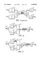
- FIG. 1shows a prior art optical communication system using a WDM.
- FIG. 2shows an embodiment of an optical communications system using a WDM in accordance with this invention.
- FIG. 3shows a modification of the system of FIG. 2, including an optical amplifier.
- FIG. 4shows the display of an RF spectrum analyzer used to equalize path lengths (delays).
- FIG. 5shows an externally modulated optical communications system in accordance with this invention.
- FIGS. 6A, and 6Bshow various embodiments of optical communications systems in accordance with this invention, using two optical fibers and various arrangements of the transmitters and receivers.
- FIGS. 7A, 7B, 8A and 8Bshow other embodiments of optical communications systems in accordance with this invention.
- FIG. 2shows in a block diagram an optical communications system in accordance with this invention.
- the illustrated componentsare all conventional, and therefore not disclosed in greater detail.
- FIG. 2shows a system in which the two conventional optical transmitters 34 and 36 are each driven by a single RF signal applied to an input terminal of an RF splitter 30 which is connected electrically to drive the two transmitters 34 and 36, i.e. modulate their output signals.
- a transmitteris a device with an RF input and an optical output, and includes a light source.
- Transmitters 34, 36are of the directly or externally modulated type.
- the power supply components to drive transmitters 34 and 36are conventional and not shown.
- the transmitters 34 and 36output light beams respectively having wavelengths ⁇ 1 and ⁇ 2 which differ by e.g.
- Transmitters 34 and 36are coupled respectively by optical couplers 40, 44 to two input ports of a wavelength division multiplexer (WDM) 48.
- WDMwavelength division multiplexer
- WDM 48is for instance a commercially available device such as the multi-channel WDM available from DiCon Fiber Optics, Inc., of Berkeley, Calif.
- the WDM 48is a "dense WDM", i.e. the difference in wavelengths between ⁇ 1 and ⁇ 2 is small, as described above. This provides the advantage of reducing relative dispersion in the fiber link.
- Such WDMstypically have a number of input ports (not limited to two) and a single output port. They can used in the other direction, with the single port being the input port and the multiple ports being the output port.
- the single output port of WDM 48is coupled to a span of optical fiber 52, which may be many kilometers long.
- the optical fiber 52may be either a standard (non-dispersion shifted), dispersion shifted, non-zero dispersion shifted, or a dispersion compensating fiber or any combination thereof.
- the optical trainshown in block diagram form in FIG. 2, may include one or more conventional optical amplifiers (described below), optical isolators, optical couplers or splitters, or optical phase or intensity modulators as needed.
- a distal terminus of optical fiber 52(at the receiver end) is coupled to the input port of a receiver 56 which converts the received light signal into an RF output signal which at least nominally is identical to the RF input signal applied to splitter 30.
- Receiver 56may take various forms. In its simplest form, it is a single photo-sensitive diode device sensitive to both wavelengths ⁇ 1 and ⁇ 2 , but may take other forms as described further below. Where the receiver 56 is a single device, the phase of the signals ⁇ 1 and ⁇ 2 typically is adjusted, either by an electronic or optical delay, so that the phase at the receiver 56 of the received optical signals is nearly as possible the same. Achieving this is described further below.
- receiver 56includes several photo-sensitive devices, each receiving light of a particular wavelength, i.e. ⁇ 1 or ⁇ 2 , the RF output signals from which are then combined electronically, in which case the phase of the two different wavelength signals ⁇ 1 and ⁇ 2 may be adjusted optically or electrically by suitable delay elements.
- the cross talk problem present in the prior art system of FIG. 1, where there is cross talk between differing information on different optical wavelengths carried on the same RF channelis avoided; in this case, cross talk is not problematic because the identical information is carried on the same RF channel at the two distinct wavelengths ⁇ 1 and ⁇ 2 . (To the extent the information on the two channels is out of phase, this lowers amplitude at the receiver but does not cause cross talk.)
- the optimum difference in the wavelengths ⁇ 1 and ⁇ 2is dependent on the actual properties of WDM 48 and fiber span 52, as determined by experimentation.
- the output power levels of transmitters 34 and 36are matched, but this is not essential.
- FIG. 3shows another optical communications system which is a modification of that of FIG. 2; components in FIG. 3 similar to those of FIG. 2 have identical reference numbers.
- a short additional length 58 of optical fiberis coupled between transmitter 34 and the associated input port of WDM 48, to provide a phase delay to the output signal from transmitter 34 since, in this case, wavelength ⁇ 1 propagates faster through optical fiber 52 than does wavelength ⁇ 2 .
- this delaycaused by the additional fiber 58, puts the two optical signals ⁇ 1 , ⁇ 2 in phase at receiver 56.
- a conventional optical amplifier (e.g. erbium doped fiber amplifier) 66is coupled between WDM 48 and optical fiber span 52 to increase optical launch power.
- the delay element(optical fiber 58) may be as short as 51 cm of optical fiber for a 50 kilometer length of type SMF-28 optical fiber span 52, where the difference between the two wavelengths ⁇ 1 and ⁇ 2 is 3 nm in the 1550 nm region.
- Ddispersion given in units of ps/(nm ⁇ km).
- Dis about 17 ps/(nm ⁇ km) at 1550 nm.
- ⁇ tbe the time delay between two lightwaves at about 1550 nm separated by ⁇ in wavelength, after propagating through L distance of fiber.
- ⁇ tD ⁇ L.
- the delay elementneed not be as shown in FIG. 3; as described above, it may be located elsewhere, for instance interposed between the output port of RF splitter 30 and the input port of laser 34. In this case, the delay element would be an electrical (RF) delay.
- the delaymay also be provided (where appropriate) instead in receiver 56, as described below.
- the phase delay adjustmentis accomplished by a combination of optical delay elements and RF delay elements.
- most of the phase delay in one embodimentis accomplished by a length of optical fiber 58 as in FIG. 3, while small additional phase adjustments are made by a suitably connected adjustable RF delay line.
- the followingdescribes equalizing the lengths of the two paths with a combination of RF (coaxial cable) and optical (fiber) delay.
- Notch depthis determined by how closely matched the input levels are (at the notch frequency) while the spacing between adjacent notches depends on the delay difference between the two paths.
- a spectrum analyzer connected to the RF output of the receiver(s)enables notch-to-notch frequency spacing to be measured.
- the path length differencecan then be determined with the following equations:
- f1is any notch frequency and f2 is the next highest notch frequency. Both f2 and f1 are in units of MHz.
- FIG. 4shows the spectrum for a communications system where one notch (f1) occurs at 75 MHz and the next highest notch (f2) occurs at 125 MHz.
- the calculated amount of coaxial cableis added. Long lengths of coaxial cable may require another adjustment of the associated receiver's tilt and level controls to compensate for high frequency attenuation.
- the path lengthsit is preferable to equalize the path lengths with added optical fiber rather than in the RF domain.
- the optical fiberis then added to the shorter path.
- the use of a noise source as input to the transmittermay also be required in cases where the carrier spacing does not provide enough resolution for measuring small notch-to-notch frequency spacing. Spacing of 12 MHz or less (corresponding to 76.6 meters or more of optical fiber length difference) will need a white noise source as the transmitter RF input in order to accurately determine notch-to-notch frequency spacing.
- phase adjustmentby adjusting the operating temperature of one of the transmitter lasers or laser diodes, thereby altering its output wavelength.
- a combination of these techniques--light delay, RF delay, and wavelength adjustment--may also be used.
- FIG. 5illustrates two optical input wavelengths driving a single external modulator.
- the light signals from light sources 70 and 72are coupled respectively by couplers 74 and 76 to a WDM 80 which is similar to the type described above.
- the light signal output from WDM 80is coupled by coupler 82 to the single input port of an external modulator 86.
- Modulator 86is e.g. the dual output modulator from UTP of Bloomfield, Conn.
- the RF signalis applied to an electrical port (intensity or phase modulation port) of modulator 86.
- the fiber optical span 90then receives the multiplexed and modulated optical signal, which is thereby transmitted to a receiver 56, shown here in greater detail.
- receiver 56is more sophisticated than the type discussed above.
- the input light signal from optical fiber span 90is demultiplexed by WDM 96 (similar to WDM 80 but reverse-connected) and applied to two couplers 98 and 100 which are in turn coupled to photodiodes 104 and 108 which are respectively sensitive to wavelengths ⁇ 1 and ⁇ 2 as output by WDM 96.
- Photodiodes 104 and 108respectively output RF signals which are then applied to an RF combiner 110 which outputs the RF output signal.
- any phase delayis provided either in coupler 98 as an optical delay line or as an electrical delay in RF combiner 110.
- An optical amplifier(s) as shown in FIG. 3may be used in this embodiment as needed.
- While these embodimentsshow a WDM in the transmitter and/or receiver to which two different wavelengths ⁇ 1 and ⁇ 2 are applied, it is to be understood that such a WDM may multiplex or demultiplex three or more wavelengths.
- an additional transmitter(s)are coupled to the transmitter side WDM in the FIGS. 2, 3 or 5 embodiments. This provides additional power, depending on the number of additional laser sources used.
- Each photodiode in the receiver 56can receive optical power up to its distortion limit. This limit is 3 dBm for example, and a two wavelength-two photodiode receiver as in FIG. 5 can effectively increase the total received optical power to 6 dBm without distortion. (This increases the RF signal strength without exceeding the RF distortion limit of any photodiode.)
- FIG. 6AA modification to the system of FIG. 5 is shown in FIG. 6A.
- the transmitter sectionis essentially identical, except that the modulator 86 has two output ports outputting two optical signals which are shown to be respectively at 0° and 180° in terms of their relative phases.
- Such a modulatoris known from Nazarathy et al., U.S. Pat. No. 5,253,309, issued Oct. 12, 1993 and incorporated herein by reference (see e.g. FIG. 9).
- Optical amplifiers 120 and 122are incorporated as described above.
- the lower channel in FIG. 6Aincludes the 180° output port of modulator 86 coupled by connector 118 to optical amplifier 122, driving a second fiber optic span 90a.
- the receiverhere includes two cross-coupled receivers of the type shown in FIG. 5 with the components numbered similarly as in FIG. 5.
- the two receiversare cross-coupled (in the RF domain) by RF combiners 110 and 110A, each receiving a signal from both the upper and lower channel.
- the output signals from combiners 110 and 110Aare combined by a third combiner 130 to provide the actual RF output signal.
- This receiverwhich uses differential detection, is easily understood in light of the above-referenced patent, and each combiner 110, 110A and 130 is of the type described in that patent.
- the RF signalmay improved in terms of power by 3 dB by use of two channels, with reduced distortion (CTB).
- each transmitter 34outputs two output signals by incorporation of an appropriate modulator as described in the above-referenced patent.
- transmitter 34provides an output signal on coupler 58 and a second on coupler 58a, each 180° out of phase with one another as shown. The same is true for the second transmitter 36.
- These output signalsare cross-coupled into two WDMs 48 and 48a where WDM 48 receives the 0° (in phase) optical signals and WDM 48A receives the 180° (out of phase) optical signals.
- WDM 48 and 48arespectively drive the upper and lower channels, each of which has its own receiver 56, 56a of one of the types described above using the known differential detection.
- the RF signals from receivers 56 and 56aare combined by an RF combiner 140 again of the type described in the above-referenced patent.
- Yet another embodimentwould have a transmitter system as in FIG. 6B and a receiver system as in FIG. 6A.
- FIGS. 7A and 7Bshow two somewhat different optical communications systems according to this invention; both use elements as described above.
- an RF signal to be transmittedis applied to an RF splitter 142 with two output arms, connected respectively to delay elements (RF delay) 146 and 148 which in turn couple the RF signal into the first transmitter 152 and the second transmitter 156, outputting light signals at respectively wavelengths ⁇ 1 and ⁇ 2 .
- the labels T1 and T2refer to the operating temperatures of the laser diodes or lasers in respectively transmitters 152 and 156.
- the optical signals from transmitters 152 and 156are coupled via optical delay elements 160 and 162 (the letter d refers to a delay element in these figures) to optical fiber spans 170 and 172, each of which is coupled into an input port of a wave division multiplexer (WDM) 180.
- WDMwave division multiplexer
- the output port of WDM 180is coupled to a receiver 188 by a second fiber optic span 182.
- the receiver 188outputs an RF signal RF out .
- the spanis either a combination of two optical fibers 170, 172 or a single optical fiber 182.
- the first optical fiber span 170carries a signal having wavelength ⁇ 1 and the second optical fiber 172 carries a signal having wavelength ⁇ 2 . If the span is the single optical fiber 182, it carries two wavelengths ⁇ 1 , ⁇ 2 .
- WDM 194drives two optical delay elements 196, 198 which respectively are coupled to receivers 202 and 204 which output RF signals which are delayed by respectively RF delay elements 210, 212.
- the output signals from delay elements 210, 212are combined by RF combiner 216 to produce the RF out signal.
- the delayis only present at the transmitter end.
- FIGS. 8A and 8Bshow additional embodiments in accordance with this invention with external modulation of the light sources.
- the first light source 230outputs a light beam having wavelength ⁇ 1 and the second light source 232 outputs a light beam having wavelength ⁇ 2 ; light sources 230, 232 operate respectively at different temperatures T1 and T2.
- Light sources 230 and 232both drive WDM 236 which provides an output optical signal to the external modulator 238 which is driven by the RF signal.
- the optical output signal from modulator 238is coupled to an optical fiber span 242, the other end of which is coupled to a second WDM 244 which provides two output signals coupled to respectively fiber spans 246 and 248.
- the actual optical fiber spani.e., the long span
- the receiver ends of spans 246 and 248are coupled respectively to optical delay elements 250, 252 which in turn drive receivers 254, 256.
- Receivers 254, 256provide RF signals to delay elements 260 and 262, the output signals from which are combined by RF combiner 266 to provide the RF out signal.
- FIG. 8BA variant of the FIG. 8A embodiment is shown in FIG. 8B, where at the right hand portion of the figure, the WDM 244 drives two delay elements 250, 252 which are in turn coupled to a third WDM 274 which in turn drives the fiber span 278, the other end which is coupled to, a receiver 280.
- the only delay providedis by the optical delay elements 250, 252.
- the present inventionmay be combined with the SBS-suppressing modulation approach described in copending U.S. patent application Ser. No. 08/559,057, filed Nov. 16, 1996 by Alan C. Nilsson, entitled Multi-Tone Phase Modulation In Light Signal Wave Communication System, incorporated herein by reference.
- Channel foldingis a consequence of the multi-tone phase modulation that results in possibly higher noise, i.e. lower CNR, at certain RF frequencies.
- channelor SBS suppression induced high channel noise
Landscapes
- Engineering & Computer Science (AREA)
- Computer Networks & Wireless Communication (AREA)
- Signal Processing (AREA)
- Physics & Mathematics (AREA)
- Electromagnetism (AREA)
- Optical Communication System (AREA)
Abstract
Description
______________________________________Required (meters) = 200/(f2-f1); yields theLength: required optical fiber length (This equation is valid at both 1310 nm and 1550 nm.)or (meters) = 237/(f2-f1); yields the required coaxial cable length______________________________________
______________________________________ Required optical = 200/(125-75) fiber length = 200/50 = 4 metersor Required coaxial = 237/(125-75) cable length = 237/50 = 4.7 meters______________________________________
Claims (23)
Priority Applications (1)
| Application Number | Priority Date | Filing Date | Title |
|---|---|---|---|
| US08/858,067US5940196A (en) | 1997-05-16 | 1997-05-16 | Optical communications system with wavelength division multiplexing |
Applications Claiming Priority (1)
| Application Number | Priority Date | Filing Date | Title |
|---|---|---|---|
| US08/858,067US5940196A (en) | 1997-05-16 | 1997-05-16 | Optical communications system with wavelength division multiplexing |
Publications (1)
| Publication Number | Publication Date |
|---|---|
| US5940196Atrue US5940196A (en) | 1999-08-17 |
Family
ID=25327401
Family Applications (1)
| Application Number | Title | Priority Date | Filing Date |
|---|---|---|---|
| US08/858,067Expired - LifetimeUS5940196A (en) | 1997-05-16 | 1997-05-16 | Optical communications system with wavelength division multiplexing |
Country Status (1)
| Country | Link |
|---|---|
| US (1) | US5940196A (en) |
Cited By (96)
| Publication number | Priority date | Publication date | Assignee | Title |
|---|---|---|---|---|
| US6122086A (en)* | 1995-08-16 | 2000-09-19 | Telefonaktiebolaget Lm Ericsson | Compensation of dispersion |
| WO2000077956A1 (en)* | 1999-06-10 | 2000-12-21 | Fiberspace, Inc. | Method and apparatus of utilizing rf/microwave mixing techniques to select a given band of an optical transmission |
| US6246500B1 (en)* | 1998-09-18 | 2001-06-12 | Massachusetts Institute Of Technology | Linearization of a broadband analog optical link using two wavelengths |
| EP1107487A1 (en)* | 1999-11-30 | 2001-06-13 | JDS Uniphase Inc. | Optical link for the transmission of a RF signal eliminating distortions |
| KR20010099451A (en)* | 2001-09-28 | 2001-11-09 | 허진호 | System of Optical transmission |
| US6359716B1 (en)* | 1999-02-24 | 2002-03-19 | Massachusetts Institute Of Technology | All-optical analog FM optical receiver |
| US6400478B1 (en) | 1998-04-02 | 2002-06-04 | Sorrento Networks, Inc. | Wavelength-division-multiplexed optical transmission system with expanded bidirectional transmission capacity over a single fiber |
| US20020077787A1 (en)* | 2000-12-18 | 2002-06-20 | Theodore Rappaport | Textual and graphical demarcation of location, and interpretation of measurements |
| WO2002051042A3 (en)* | 2000-12-19 | 2002-08-29 | Scientific Atlanta | Method and apparatus for suppressing relative intensity noise (rin) and improving transmission signals |
| US20020186436A1 (en)* | 2001-06-08 | 2002-12-12 | Sanjay Mani | Method and apparatus for multiplexing in a wireless communication infrastructure |
| US6496290B1 (en)* | 1998-01-31 | 2002-12-17 | Lg Telecom, Inc. | Optic repeater system for extending coverage |
| US20020191565A1 (en)* | 2001-06-08 | 2002-12-19 | Sanjay Mani | Methods and systems employing receive diversity in distributed cellular antenna applications |
| US20030014233A1 (en)* | 1999-07-14 | 2003-01-16 | Rappaport Theodore S. | System for the three-dimensional display of wireless communication system performance |
| US20030023412A1 (en)* | 2001-02-14 | 2003-01-30 | Rappaport Theodore S. | Method and system for modeling and managing terrain, buildings, and infrastructure |
| US20030050878A1 (en)* | 1999-05-26 | 2003-03-13 | Rappaport Theodore S. | Method and system for generating a real time bill of materials and evaluating network performance |
| US6559986B1 (en)* | 1997-03-12 | 2003-05-06 | Siemens Aktiengesellschaft | Method for converting the signal modulation of channels of an optical multiplex system to subcarrier frequencies |
| US6580535B1 (en) | 1999-12-28 | 2003-06-17 | Telefonaktiebolaget Lm Ericsson (Publ) | Polarization division multiplexing in optical data transmission systems |
| US6619866B1 (en) | 1998-05-01 | 2003-09-16 | The United States Of America As Represented By The Secretary Of The Navy | Dynamic range extended for optical transmitters |
| US6661814B1 (en)* | 2002-12-31 | 2003-12-09 | Intel Corporation | Method and apparatus for suppressing stimulated brillouin scattering in fiber links |
| US6671436B2 (en)* | 1998-09-16 | 2003-12-30 | Jolt Ltd. | Wireless optical communications without electronics |
| US6721769B1 (en) | 1999-05-26 | 2004-04-13 | Wireless Valley Communications, Inc. | Method and system for a building database manipulator |
| US20040133415A1 (en)* | 2000-08-04 | 2004-07-08 | Theodore Rappaport | Method and system, with component kits, for designing or deploying a communications network which considers frequency dependent effects |
| US20040143428A1 (en)* | 2003-01-22 | 2004-07-22 | Rappaport Theodore S. | System and method for automated placement or configuration of equipment for obtaining desired network performance objectives |
| US20040198453A1 (en)* | 2002-09-20 | 2004-10-07 | David Cutrer | Distributed wireless network employing utility poles and optical signal distribution |
| EP1056228A3 (en)* | 1999-05-28 | 2004-11-03 | Northrop Grumman Corporation | Linearized optical link using a single Mach-Zender modulator and two optical carriers |
| US20040229623A1 (en)* | 1999-05-26 | 2004-11-18 | Rappaport Theodore S. | Method and system for analysis, design, and optimization of communication networks |
| US6826163B2 (en) | 2001-06-08 | 2004-11-30 | Nextg Networks | Method and apparatus for multiplexing in a wireless communication infrastructure |
| US6826164B2 (en) | 2001-06-08 | 2004-11-30 | Nextg Networks | Method and apparatus for multiplexing in a wireless communication infrastructure |
| WO2004112285A1 (en)* | 2003-06-13 | 2004-12-23 | Matsushita Electric Industrial Co., Ltd. | System, device, and method for radio frequency optical transmission |
| US20040259554A1 (en)* | 2003-04-23 | 2004-12-23 | Rappaport Theodore S. | System and method for ray tracing using reception surfaces |
| US20040259555A1 (en)* | 2003-04-23 | 2004-12-23 | Rappaport Theodore S. | System and method for predicting network performance and position location using multiple table lookups |
| US6850710B1 (en) | 2000-06-09 | 2005-02-01 | Tip Group, Llc | Method and apparatus of utilizing RF/microwave and optical mixing techniques to select a given band of an optical transmission |
| US20050043933A1 (en)* | 2000-08-04 | 2005-02-24 | Theodore Rappaport | System and method for efficiently visualizing and comparing communication network system performance |
| US20050047799A1 (en)* | 2003-08-26 | 2005-03-03 | Coppinger Frederic M.A. | Method and apparatus to reduce second order distortion in optical communications |
| US6876951B2 (en) | 1998-12-29 | 2005-04-05 | Wireless Valley Communications, Inc. | Method for creating a computer model and measurement database of a wireless communication network |
| US20050105908A1 (en)* | 1999-07-15 | 2005-05-19 | Fujitsu Limited | Optical repeater converting wavelength and bit rate between networks |
| US6971063B1 (en) | 2000-07-28 | 2005-11-29 | Wireless Valley Communications Inc. | System, method, and apparatus for portable design, deployment, test, and optimization of a communication network |
| US20050265321A1 (en)* | 2000-09-25 | 2005-12-01 | Theodore Rappaport | System and method for design, tracking, measurement, prediction and optimization of data communication networks |
| US7055107B1 (en) | 2000-09-22 | 2006-05-30 | Wireless Valley Communications, Inc. | Method and system for automated selection of optimal communication network equipment model, position, and configuration |
| US20060116853A1 (en)* | 2001-12-17 | 2006-06-01 | Theodore Rappaport | Textual and graphical demarcation of location, and interpretation of measurments |
| US7076168B1 (en)* | 1998-02-12 | 2006-07-11 | Aquity, Llc | Method and apparatus for using multicarrier interferometry to enhance optical fiber communications |
| US7085697B1 (en) | 2000-08-04 | 2006-08-01 | Motorola, Inc. | Method and system for designing or deploying a communications network which considers component attributes |
| US7096173B1 (en) | 2000-08-04 | 2006-08-22 | Motorola, Inc. | Method and system for designing or deploying a communications network which allows simultaneous selection of multiple components |
| US7171208B2 (en) | 2000-08-04 | 2007-01-30 | Motorola, Inc. | Method and system, with component kits for designing or deploying a communications network which considers frequency dependent effects |
| US20070099622A1 (en)* | 2005-04-18 | 2007-05-03 | Theodore Rappaport | Method and apparatus for utilizing RF signals to create a site specific representation of an environment |
| US7243054B2 (en) | 1999-07-14 | 2007-07-10 | Wireless Valley Communications, Inc. | Method and system for displaying network performance, cost, maintenance, and infrastructure wiring diagram |
| US7245833B1 (en)* | 2002-11-15 | 2007-07-17 | Itt Manufacturing Enterprises, Inc. | Photonic channelized RF receiver employing dense wavelength division multiplexing |
| US20070211786A1 (en)* | 1998-02-12 | 2007-09-13 | Steve Shattil | Multicarrier Sub-Layer for Direct Sequence Channel and Multiple-Access Coding |
| US7295119B2 (en) | 2003-01-22 | 2007-11-13 | Wireless Valley Communications, Inc. | System and method for indicating the presence or physical location of persons or devices in a site specific representation of a physical environment |
| US20070298805A1 (en)* | 2006-06-27 | 2007-12-27 | Motorola, Inc. | Method and system for analysis and visualization of a wireless communications network |
| US20090110033A1 (en)* | 1998-02-12 | 2009-04-30 | Lot 41 Acquisition Foundation, Llc | Multicarrier sub-layer for direct sequence channel and multiple-access coding |
| US7548695B2 (en)* | 2004-10-19 | 2009-06-16 | Nextg Networks, Inc. | Wireless signal distribution system and method |
| US20090285577A1 (en)* | 2008-05-13 | 2009-11-19 | Nec Laboratories America, Inc. | Optical Frontend for Integration of Optical and Wireless Networks |
| US20100183294A1 (en)* | 2009-01-16 | 2010-07-22 | Fernando Xavier Villarruel | Sparing for multi-wavelength optical transmitter |
| US20100312828A1 (en)* | 2009-06-03 | 2010-12-09 | Mobixell Networks Ltd. | Server-controlled download of streaming media files |
| US20110225315A1 (en)* | 2010-03-09 | 2011-09-15 | Mobixell Networks Ltd. | Multi-stream bit rate adaptation |
| WO2011123687A1 (en)* | 2010-03-31 | 2011-10-06 | Ultra Communications, Inc. | Integrated optical time domain reflectometer |
| US8059969B1 (en)* | 2008-06-18 | 2011-11-15 | Hrl Laboratories, Llc | Enhanced linearity RF photonic link |
| US8180183B1 (en) | 2008-07-18 | 2012-05-15 | Hrl Laboratories, Llc | Parallel modulator photonic link |
| US20120315049A1 (en)* | 2008-11-20 | 2012-12-13 | Telcordia Technologies, Inc. | Method and apparatus for optimized analog rf optical links |
| US20130188962A1 (en)* | 2012-01-24 | 2013-07-25 | Harris Corporation | Communications device with discriminator for generating intermediate frequency signal and related methods |
| US20130188952A1 (en)* | 2012-01-24 | 2013-07-25 | Harris Corporation Corporation Of The State Of Delaware | Communications device with discriminator and wavelength division multiplexing for generating intermediate frequency signal and related methods |
| US8688074B2 (en) | 2011-02-28 | 2014-04-01 | Moisixell Networks Ltd. | Service classification of web traffic |
| US8750709B1 (en) | 2008-07-18 | 2014-06-10 | Hrl Laboratories, Llc | RF receiver front-end assembly |
| US8832709B2 (en) | 2010-07-19 | 2014-09-09 | Flash Networks Ltd. | Network optimization |
| US8879919B2 (en) | 2011-09-09 | 2014-11-04 | Harris Corporation | Photonic communications device with an FM/PM discriminator and related methods |
| US8995838B1 (en) | 2008-06-18 | 2015-03-31 | Hrl Laboratories, Llc | Waveguide assembly for a microwave receiver with electro-optic modulator |
| US9335568B1 (en) | 2011-06-02 | 2016-05-10 | Hrl Laboratories, Llc | Electro-optic grating modulator |
| US9485012B2 (en)* | 2014-10-15 | 2016-11-01 | Infinera Corporation | Optical link protection using common modulation of multiple combined wavelengths |
| US9485063B2 (en) | 2001-04-26 | 2016-11-01 | Genghiscomm Holdings, LLC | Pre-coding in multi-user MIMO |
| US9548878B2 (en) | 2008-03-12 | 2017-01-17 | Hypres, Inc. | Digital radio frequency transceiver system and method |
| US9628231B2 (en) | 2002-05-14 | 2017-04-18 | Genghiscomm Holdings, LLC | Spreading and precoding in OFDM |
| US9893774B2 (en) | 2001-04-26 | 2018-02-13 | Genghiscomm Holdings, LLC | Cloud radio access network |
| US10142082B1 (en) | 2002-05-14 | 2018-11-27 | Genghiscomm Holdings, LLC | Pre-coding in OFDM |
| US10200227B2 (en) | 2002-05-14 | 2019-02-05 | Genghiscomm Holdings, LLC | Pre-coding in multi-user MIMO |
| US10305636B1 (en) | 2004-08-02 | 2019-05-28 | Genghiscomm Holdings, LLC | Cooperative MIMO |
| US10355720B2 (en) | 2001-04-26 | 2019-07-16 | Genghiscomm Holdings, LLC | Distributed software-defined radio |
| US10425135B2 (en) | 2001-04-26 | 2019-09-24 | Genghiscomm Holdings, LLC | Coordinated multipoint systems |
| US10644916B1 (en) | 2002-05-14 | 2020-05-05 | Genghiscomm Holdings, LLC | Spreading and precoding in OFDM |
| US10855377B2 (en) | 2013-08-30 | 2020-12-01 | Nec Corporation | Optical transmission apparatus, optical reception apparatus, optical communication apparatus, optical communication system, and methods of controlling them |
| US10880145B2 (en) | 2019-01-25 | 2020-12-29 | Genghiscomm Holdings, LLC | Orthogonal multiple access and non-orthogonal multiple access |
| US10931338B2 (en) | 2001-04-26 | 2021-02-23 | Genghiscomm Holdings, LLC | Coordinated multipoint systems |
| US10951322B2 (en)* | 2018-03-01 | 2021-03-16 | Thales | Dual-band photonic device and method for converting frequency |
| US11018918B1 (en) | 2017-05-25 | 2021-05-25 | Genghiscomm Holdings, LLC | Peak-to-average-power reduction for OFDM multiple access |
| US11115160B2 (en) | 2019-05-26 | 2021-09-07 | Genghiscomm Holdings, LLC | Non-orthogonal multiple access |
| US11184037B1 (en) | 2004-08-02 | 2021-11-23 | Genghiscomm Holdings, LLC | Demodulating and decoding carrier interferometry signals |
| US11196603B2 (en) | 2017-06-30 | 2021-12-07 | Genghiscomm Holdings, LLC | Efficient synthesis and analysis of OFDM and MIMO-OFDM signals |
| US11201677B1 (en)* | 2020-06-08 | 2021-12-14 | Raytheon Company | Hard-to-intercept multiple coherent transmitter communications |
| US11303360B2 (en)* | 2020-06-22 | 2022-04-12 | Raytheon Company | Methods and apparatus supporting non-persistent communications |
| US11343823B2 (en) | 2020-08-16 | 2022-05-24 | Tybalt, Llc | Orthogonal multiple access and non-orthogonal multiple access |
| US11381285B1 (en) | 2004-08-02 | 2022-07-05 | Genghiscomm Holdings, LLC | Transmit pre-coding |
| US11552737B1 (en) | 2004-08-02 | 2023-01-10 | Genghiscomm Holdings, LLC | Cooperative MIMO |
| US11916595B1 (en)* | 2023-08-28 | 2024-02-27 | The Jalali Family Trust Dated December 30, 2006. | Wavelength-multiplexed subranging electro-optic modulator (SEOM) for high dynamic range applications |
| US11917604B2 (en) | 2019-01-25 | 2024-02-27 | Tybalt, Llc | Orthogonal multiple access and non-orthogonal multiple access |
| US12206535B1 (en) | 2018-06-17 | 2025-01-21 | Tybalt, Llc | Artificial neural networks in wireless communication systems |
| US12224860B1 (en) | 2014-01-30 | 2025-02-11 | Genghiscomm Holdings, LLC | Linear coding in decentralized networks |
Citations (8)
| Publication number | Priority date | Publication date | Assignee | Title |
|---|---|---|---|---|
| US4393518A (en)* | 1981-01-16 | 1983-07-12 | Bell Telephone Laboratories, Incorporated | Optical communication arrangement |
| US5023945A (en)* | 1989-12-21 | 1991-06-11 | Gte Laboratories Incorporated | Transmission system using parallel optic links to achieve enhanced dynamic range |
| US5126871A (en)* | 1989-11-15 | 1992-06-30 | General Instrument Corporation | Method and apparatus for redundant communication of optical signals with distortion cancellation |
| US5162937A (en)* | 1990-01-16 | 1992-11-10 | Alcatel N.V. | Optical cable television transmission system |
| US5253309A (en)* | 1989-06-23 | 1993-10-12 | Harmonic Lightwaves, Inc. | Optical distribution of analog and digital signals using optical modulators with complementary outputs |
| US5257124A (en)* | 1991-08-15 | 1993-10-26 | General Instrument Corporation | Low distortion laser system for AM fiber optic communication |
| US5278688A (en)* | 1990-04-24 | 1994-01-11 | Ortel Corporation | Fault tolerant fiber optic transmission system |
| US5430568A (en)* | 1992-12-01 | 1995-07-04 | Scientific-Atlanta, Inc. | Optical communications system for transmitting information signals having different wavelengths over a same optical fiber |
- 1997
- 1997-05-16USUS08/858,067patent/US5940196A/ennot_activeExpired - Lifetime
Patent Citations (8)
| Publication number | Priority date | Publication date | Assignee | Title |
|---|---|---|---|---|
| US4393518A (en)* | 1981-01-16 | 1983-07-12 | Bell Telephone Laboratories, Incorporated | Optical communication arrangement |
| US5253309A (en)* | 1989-06-23 | 1993-10-12 | Harmonic Lightwaves, Inc. | Optical distribution of analog and digital signals using optical modulators with complementary outputs |
| US5126871A (en)* | 1989-11-15 | 1992-06-30 | General Instrument Corporation | Method and apparatus for redundant communication of optical signals with distortion cancellation |
| US5023945A (en)* | 1989-12-21 | 1991-06-11 | Gte Laboratories Incorporated | Transmission system using parallel optic links to achieve enhanced dynamic range |
| US5162937A (en)* | 1990-01-16 | 1992-11-10 | Alcatel N.V. | Optical cable television transmission system |
| US5278688A (en)* | 1990-04-24 | 1994-01-11 | Ortel Corporation | Fault tolerant fiber optic transmission system |
| US5257124A (en)* | 1991-08-15 | 1993-10-26 | General Instrument Corporation | Low distortion laser system for AM fiber optic communication |
| US5430568A (en)* | 1992-12-01 | 1995-07-04 | Scientific-Atlanta, Inc. | Optical communications system for transmitting information signals having different wavelengths over a same optical fiber |
Cited By (181)
| Publication number | Priority date | Publication date | Assignee | Title |
|---|---|---|---|---|
| US6122086A (en)* | 1995-08-16 | 2000-09-19 | Telefonaktiebolaget Lm Ericsson | Compensation of dispersion |
| US6559986B1 (en)* | 1997-03-12 | 2003-05-06 | Siemens Aktiengesellschaft | Method for converting the signal modulation of channels of an optical multiplex system to subcarrier frequencies |
| US6496290B1 (en)* | 1998-01-31 | 2002-12-17 | Lg Telecom, Inc. | Optic repeater system for extending coverage |
| US20070025421A1 (en)* | 1998-02-12 | 2007-02-01 | Steve Shattil | Method and Apparatus for Using Multicarrier Interferometry to Enhance optical Fiber Communications |
| US20070211786A1 (en)* | 1998-02-12 | 2007-09-13 | Steve Shattil | Multicarrier Sub-Layer for Direct Sequence Channel and Multiple-Access Coding |
| US7965761B2 (en) | 1998-02-12 | 2011-06-21 | Lot 41 Acquisition Foundation, Llc | Multicarrier sub-layer for direct sequence channel and multiple-access coding |
| US7076168B1 (en)* | 1998-02-12 | 2006-07-11 | Aquity, Llc | Method and apparatus for using multicarrier interferometry to enhance optical fiber communications |
| US20090110033A1 (en)* | 1998-02-12 | 2009-04-30 | Lot 41 Acquisition Foundation, Llc | Multicarrier sub-layer for direct sequence channel and multiple-access coding |
| US7593449B2 (en) | 1998-02-12 | 2009-09-22 | Steve Shattil | Multicarrier sub-layer for direct sequence channel and multiple-access coding |
| US7430257B1 (en) | 1998-02-12 | 2008-09-30 | Lot 41 Acquisition Foundation, Llc | Multicarrier sub-layer for direct sequence channel and multiple-access coding |
| US6400478B1 (en) | 1998-04-02 | 2002-06-04 | Sorrento Networks, Inc. | Wavelength-division-multiplexed optical transmission system with expanded bidirectional transmission capacity over a single fiber |
| US6619866B1 (en) | 1998-05-01 | 2003-09-16 | The United States Of America As Represented By The Secretary Of The Navy | Dynamic range extended for optical transmitters |
| US6671436B2 (en)* | 1998-09-16 | 2003-12-30 | Jolt Ltd. | Wireless optical communications without electronics |
| US6246500B1 (en)* | 1998-09-18 | 2001-06-12 | Massachusetts Institute Of Technology | Linearization of a broadband analog optical link using two wavelengths |
| US6876951B2 (en) | 1998-12-29 | 2005-04-05 | Wireless Valley Communications, Inc. | Method for creating a computer model and measurement database of a wireless communication network |
| US7096160B2 (en) | 1998-12-29 | 2006-08-22 | Wireless Valley Communications, Inc. | System and method for measuring and monitoring wireless network performance in campus and indoor environments |
| US6359716B1 (en)* | 1999-02-24 | 2002-03-19 | Massachusetts Institute Of Technology | All-optical analog FM optical receiver |
| US20030050878A1 (en)* | 1999-05-26 | 2003-03-13 | Rappaport Theodore S. | Method and system for generating a real time bill of materials and evaluating network performance |
| US6850946B1 (en) | 1999-05-26 | 2005-02-01 | Wireless Valley Communications, Inc. | Method and system for a building database manipulator |
| US7155228B2 (en) | 1999-05-26 | 2006-12-26 | Wireless Valley Communications, Inc. | Method and system for analysis, design, and optimization of communication networks |
| US7596518B2 (en) | 1999-05-26 | 2009-09-29 | Wireless Valley Communications, Inc. | Method and system for generating a real time bill of materials and evaluating network performance |
| US6721769B1 (en) | 1999-05-26 | 2004-04-13 | Wireless Valley Communications, Inc. | Method and system for a building database manipulator |
| US20050131619A1 (en)* | 1999-05-26 | 2005-06-16 | Rappaport Theodore S. | Method and system for a building database manipulator |
| US7711687B2 (en) | 1999-05-26 | 2010-05-04 | Wireless Valley Communications, Inc. | Method and system for using raster images to create a transportable building database for communications network engineering and management |
| US20040162840A1 (en)* | 1999-05-26 | 2004-08-19 | Theodore Rappaport | System and method for a three dimensional database modeler for wireless communications network management and engineering |
| US20040229623A1 (en)* | 1999-05-26 | 2004-11-18 | Rappaport Theodore S. | Method and system for analysis, design, and optimization of communication networks |
| US20040177085A1 (en)* | 1999-05-26 | 2004-09-09 | Theodore Rappaport | Method and system for using raster images to create a transportable building database for communications network engineering and management |
| US20040186847A1 (en)* | 1999-05-26 | 2004-09-23 | Rappaport Theodore S. | Method and apparatus for a transportable environmental database for communications network management and engineering |
| EP1056228A3 (en)* | 1999-05-28 | 2004-11-03 | Northrop Grumman Corporation | Linearized optical link using a single Mach-Zender modulator and two optical carriers |
| US7079780B1 (en)* | 1999-05-28 | 2006-07-18 | Northrop Grumman Corporation | Linearized optical link using a single Mach-Zehnder modulator and two optical carriers |
| WO2000077956A1 (en)* | 1999-06-10 | 2000-12-21 | Fiberspace, Inc. | Method and apparatus of utilizing rf/microwave mixing techniques to select a given band of an optical transmission |
| US20030014233A1 (en)* | 1999-07-14 | 2003-01-16 | Rappaport Theodore S. | System for the three-dimensional display of wireless communication system performance |
| US7299168B2 (en) | 1999-07-14 | 2007-11-20 | Wireless Valley Communications, Inc. | System for the three-dimensional display of wireless communication system performance |
| US7243054B2 (en) | 1999-07-14 | 2007-07-10 | Wireless Valley Communications, Inc. | Method and system for displaying network performance, cost, maintenance, and infrastructure wiring diagram |
| US7522843B2 (en) | 1999-07-15 | 2009-04-21 | Fujitsu Limited | Optical repeater converting wavelength and bit rate between networks |
| US7424227B2 (en)* | 1999-07-15 | 2008-09-09 | Fujitsu Limited | Optical repeater converting wavelength and bit rate between networks |
| US20090028577A1 (en)* | 1999-07-15 | 2009-01-29 | Fujitsu Limited | Optical repeater converting wavelength and bit rate between networks |
| US20050105908A1 (en)* | 1999-07-15 | 2005-05-19 | Fujitsu Limited | Optical repeater converting wavelength and bit rate between networks |
| US6634811B1 (en) | 1999-11-30 | 2003-10-21 | Jds Corporation | High performance optical link |
| EP1107487A1 (en)* | 1999-11-30 | 2001-06-13 | JDS Uniphase Inc. | Optical link for the transmission of a RF signal eliminating distortions |
| US6580535B1 (en) | 1999-12-28 | 2003-06-17 | Telefonaktiebolaget Lm Ericsson (Publ) | Polarization division multiplexing in optical data transmission systems |
| US6850710B1 (en) | 2000-06-09 | 2005-02-01 | Tip Group, Llc | Method and apparatus of utilizing RF/microwave and optical mixing techniques to select a given band of an optical transmission |
| US6971063B1 (en) | 2000-07-28 | 2005-11-29 | Wireless Valley Communications Inc. | System, method, and apparatus for portable design, deployment, test, and optimization of a communication network |
| US20060015814A1 (en)* | 2000-07-28 | 2006-01-19 | Rappaport Theodore S | System, method, and apparatus for portable design, deployment, test, and optimization of a communication network |
| US7286971B2 (en) | 2000-08-04 | 2007-10-23 | Wireless Valley Communications, Inc. | System and method for efficiently visualizing and comparing communication network system performance |
| US7933605B2 (en) | 2000-08-04 | 2011-04-26 | Motorola Solutions, Inc. | Method and system, with component kits for designing or deploying a communications network which considers frequency dependent effects |
| US20070117567A1 (en)* | 2000-08-04 | 2007-05-24 | Wireless Valley Communications, Inc. | Method and system, with component kits for designing or deploying a communications network which considers frequency dependent effects |
| US7680644B2 (en) | 2000-08-04 | 2010-03-16 | Wireless Valley Communications, Inc. | Method and system, with component kits, for designing or deploying a communications network which considers frequency dependent effects |
| US8290499B2 (en) | 2000-08-04 | 2012-10-16 | Wireless Valley Communications Inc. | Method and system to model frequency dependent effects of a communciations network |
| US7171208B2 (en) | 2000-08-04 | 2007-01-30 | Motorola, Inc. | Method and system, with component kits for designing or deploying a communications network which considers frequency dependent effects |
| US20050043933A1 (en)* | 2000-08-04 | 2005-02-24 | Theodore Rappaport | System and method for efficiently visualizing and comparing communication network system performance |
| US7246045B1 (en) | 2000-08-04 | 2007-07-17 | Wireless Valley Communication, Inc. | System and method for efficiently visualizing and comparing communication network system performance |
| US7085697B1 (en) | 2000-08-04 | 2006-08-01 | Motorola, Inc. | Method and system for designing or deploying a communications network which considers component attributes |
| US7096173B1 (en) | 2000-08-04 | 2006-08-22 | Motorola, Inc. | Method and system for designing or deploying a communications network which allows simultaneous selection of multiple components |
| US20040133415A1 (en)* | 2000-08-04 | 2004-07-08 | Theodore Rappaport | Method and system, with component kits, for designing or deploying a communications network which considers frequency dependent effects |
| US7055107B1 (en) | 2000-09-22 | 2006-05-30 | Wireless Valley Communications, Inc. | Method and system for automated selection of optimal communication network equipment model, position, and configuration |
| US6973622B1 (en) | 2000-09-25 | 2005-12-06 | Wireless Valley Communications, Inc. | System and method for design, tracking, measurement, prediction and optimization of data communication networks |
| US8503336B2 (en) | 2000-09-25 | 2013-08-06 | Wireless Valley Communications, Inc | System and method for design, tracking, measurement, prediction and optimization of data communication networks |
| US20050265321A1 (en)* | 2000-09-25 | 2005-12-01 | Theodore Rappaport | System and method for design, tracking, measurement, prediction and optimization of data communication networks |
| US7019753B2 (en) | 2000-12-18 | 2006-03-28 | Wireless Valley Communications, Inc. | Textual and graphical demarcation of location from an environmental database, and interpretation of measurements including descriptive metrics and qualitative values |
| US20020077787A1 (en)* | 2000-12-18 | 2002-06-20 | Theodore Rappaport | Textual and graphical demarcation of location, and interpretation of measurements |
| US6785474B2 (en) | 2000-12-19 | 2004-08-31 | Scientific-Atlanta, Inc. | Method and apparatus for suppressing relative intensity noise (RIN) and improving transmission signals |
| WO2002051042A3 (en)* | 2000-12-19 | 2002-08-29 | Scientific Atlanta | Method and apparatus for suppressing relative intensity noise (rin) and improving transmission signals |
| US7164883B2 (en) | 2001-02-14 | 2007-01-16 | Motorola. Inc. | Method and system for modeling and managing terrain, buildings, and infrastructure |
| US20030023412A1 (en)* | 2001-02-14 | 2003-01-30 | Rappaport Theodore S. | Method and system for modeling and managing terrain, buildings, and infrastructure |
| US10425135B2 (en) | 2001-04-26 | 2019-09-24 | Genghiscomm Holdings, LLC | Coordinated multipoint systems |
| US10797733B1 (en) | 2001-04-26 | 2020-10-06 | Genghiscomm Holdings, LLC | Distributed antenna systems |
| US10355720B2 (en) | 2001-04-26 | 2019-07-16 | Genghiscomm Holdings, LLC | Distributed software-defined radio |
| US11424792B2 (en) | 2001-04-26 | 2022-08-23 | Genghiscomm Holdings, LLC | Coordinated multipoint systems |
| US10797732B1 (en) | 2001-04-26 | 2020-10-06 | Genghiscomm Holdings, LLC | Distributed antenna systems |
| US10931338B2 (en) | 2001-04-26 | 2021-02-23 | Genghiscomm Holdings, LLC | Coordinated multipoint systems |
| US9485063B2 (en) | 2001-04-26 | 2016-11-01 | Genghiscomm Holdings, LLC | Pre-coding in multi-user MIMO |
| US9893774B2 (en) | 2001-04-26 | 2018-02-13 | Genghiscomm Holdings, LLC | Cloud radio access network |
| US20020186436A1 (en)* | 2001-06-08 | 2002-12-12 | Sanjay Mani | Method and apparatus for multiplexing in a wireless communication infrastructure |
| US20020191565A1 (en)* | 2001-06-08 | 2002-12-19 | Sanjay Mani | Methods and systems employing receive diversity in distributed cellular antenna applications |
| US6826164B2 (en) | 2001-06-08 | 2004-11-30 | Nextg Networks | Method and apparatus for multiplexing in a wireless communication infrastructure |
| US6826163B2 (en) | 2001-06-08 | 2004-11-30 | Nextg Networks | Method and apparatus for multiplexing in a wireless communication infrastructure |
| US7127175B2 (en) | 2001-06-08 | 2006-10-24 | Nextg Networks | Method and apparatus for multiplexing in a wireless communication infrastructure |
| KR20010099451A (en)* | 2001-09-28 | 2001-11-09 | 허진호 | System of Optical transmission |
| US20060116853A1 (en)* | 2001-12-17 | 2006-06-01 | Theodore Rappaport | Textual and graphical demarcation of location, and interpretation of measurments |
| US7574323B2 (en) | 2001-12-17 | 2009-08-11 | Wireless Valley Communications, Inc. | Textual and graphical demarcation of location, and interpretation of measurements |
| US10587369B1 (en) | 2002-05-14 | 2020-03-10 | Genghiscomm Holdings, LLC | Cooperative subspace multiplexing |
| US10009208B1 (en) | 2002-05-14 | 2018-06-26 | Genghiscomm Holdings, LLC | Spreading and precoding in OFDM |
| US9628231B2 (en) | 2002-05-14 | 2017-04-18 | Genghiscomm Holdings, LLC | Spreading and precoding in OFDM |
| US10038584B1 (en) | 2002-05-14 | 2018-07-31 | Genghiscomm Holdings, LLC | Spreading and precoding in OFDM |
| US9768842B2 (en) | 2002-05-14 | 2017-09-19 | Genghiscomm Holdings, LLC | Pre-coding in multi-user MIMO |
| US10903970B1 (en) | 2002-05-14 | 2021-01-26 | Genghiscomm Holdings, LLC | Pre-coding in OFDM |
| US10840978B2 (en) | 2002-05-14 | 2020-11-17 | Genghiscomm Holdings, LLC | Cooperative wireless networks |
| US10142082B1 (en) | 2002-05-14 | 2018-11-27 | Genghiscomm Holdings, LLC | Pre-coding in OFDM |
| US9800448B1 (en) | 2002-05-14 | 2017-10-24 | Genghiscomm Holdings, LLC | Spreading and precoding in OFDM |
| US11025312B2 (en) | 2002-05-14 | 2021-06-01 | Genghiscomm Holdings, LLC | Blind-adaptive decoding of radio signals |
| US10200227B2 (en) | 2002-05-14 | 2019-02-05 | Genghiscomm Holdings, LLC | Pre-coding in multi-user MIMO |
| US10778492B1 (en) | 2002-05-14 | 2020-09-15 | Genghiscomm Holdings, LLC | Single carrier frequency division multiple access baseband signal generation |
| US10644916B1 (en) | 2002-05-14 | 2020-05-05 | Genghiscomm Holdings, LLC | Spreading and precoding in OFDM |
| US11025468B1 (en) | 2002-05-14 | 2021-06-01 | Genghiscomm Holdings, LLC | Single carrier frequency division multiple access baseband signal generation |
| US10211892B2 (en) | 2002-05-14 | 2019-02-19 | Genghiscomm Holdings, LLC | Spread-OFDM receiver |
| US10574497B1 (en) | 2002-05-14 | 2020-02-25 | Genghiscomm Holdings, LLC | Spreading and precoding in OFDM |
| US10230559B1 (en) | 2002-05-14 | 2019-03-12 | Genghiscomm Holdings, LLC | Spreading and precoding in OFDM |
| US10389568B1 (en) | 2002-05-14 | 2019-08-20 | Genghiscomm Holdings, LLC | Single carrier frequency division multiple access baseband signal generation |
| US9967007B2 (en) | 2002-05-14 | 2018-05-08 | Genghiscomm Holdings, LLC | Cooperative wireless networks |
| US10015034B1 (en) | 2002-05-14 | 2018-07-03 | Genghiscomm Holdings, LLC | Spreading and precoding in OFDM |
| US20040198453A1 (en)* | 2002-09-20 | 2004-10-07 | David Cutrer | Distributed wireless network employing utility poles and optical signal distribution |
| US7245833B1 (en)* | 2002-11-15 | 2007-07-17 | Itt Manufacturing Enterprises, Inc. | Photonic channelized RF receiver employing dense wavelength division multiplexing |
| US6661814B1 (en)* | 2002-12-31 | 2003-12-09 | Intel Corporation | Method and apparatus for suppressing stimulated brillouin scattering in fiber links |
| US20040143428A1 (en)* | 2003-01-22 | 2004-07-22 | Rappaport Theodore S. | System and method for automated placement or configuration of equipment for obtaining desired network performance objectives |
| US7295119B2 (en) | 2003-01-22 | 2007-11-13 | Wireless Valley Communications, Inc. | System and method for indicating the presence or physical location of persons or devices in a site specific representation of a physical environment |
| US20040259555A1 (en)* | 2003-04-23 | 2004-12-23 | Rappaport Theodore S. | System and method for predicting network performance and position location using multiple table lookups |
| US20040259554A1 (en)* | 2003-04-23 | 2004-12-23 | Rappaport Theodore S. | System and method for ray tracing using reception surfaces |
| EP1639727B1 (en)* | 2003-06-13 | 2014-04-30 | Panasonic Corporation | System, device, and method for radio frequency optical transmission |
| CN1306736C (en)* | 2003-06-13 | 2007-03-21 | 松下电器产业株式会社 | System, device, and method for radio frequency optical transmission |
| US20050286907A1 (en)* | 2003-06-13 | 2005-12-29 | Matsushita Electric Industrial Co., Ltd | System, device, and method for radio frequency optical transmission |
| WO2004112285A1 (en)* | 2003-06-13 | 2004-12-23 | Matsushita Electric Industrial Co., Ltd. | System, device, and method for radio frequency optical transmission |
| US20050047799A1 (en)* | 2003-08-26 | 2005-03-03 | Coppinger Frederic M.A. | Method and apparatus to reduce second order distortion in optical communications |
| EP1511207A3 (en)* | 2003-08-26 | 2008-03-12 | Harmonic, Inc. | Method and apparatus to reduce second order distortion in optical communications |
| US11184037B1 (en) | 2004-08-02 | 2021-11-23 | Genghiscomm Holdings, LLC | Demodulating and decoding carrier interferometry signals |
| US11381285B1 (en) | 2004-08-02 | 2022-07-05 | Genghiscomm Holdings, LLC | Transmit pre-coding |
| US12095529B2 (en) | 2004-08-02 | 2024-09-17 | Genghiscomm Holdings, LLC | Spread-OFDM receiver |
| US11804882B1 (en) | 2004-08-02 | 2023-10-31 | Genghiscomm Holdings, LLC | Single carrier frequency division multiple access baseband signal generation |
| US11784686B2 (en) | 2004-08-02 | 2023-10-10 | Genghiscomm Holdings, LLC | Carrier interferometry transmitter |
| US11671299B1 (en) | 2004-08-02 | 2023-06-06 | Genghiscomm Holdings, LLC | Wireless communications using flexible channel bandwidth |
| US11646929B1 (en) | 2004-08-02 | 2023-05-09 | Genghiscomm Holdings, LLC | Spreading and precoding in OFDM |
| US11575555B2 (en) | 2004-08-02 | 2023-02-07 | Genghiscomm Holdings, LLC | Carrier interferometry transmitter |
| US11552737B1 (en) | 2004-08-02 | 2023-01-10 | Genghiscomm Holdings, LLC | Cooperative MIMO |
| US11431386B1 (en) | 2004-08-02 | 2022-08-30 | Genghiscomm Holdings, LLC | Transmit pre-coding |
| US11018917B1 (en) | 2004-08-02 | 2021-05-25 | Genghiscomm Holdings, LLC | Spreading and precoding in OFDM |
| US11075786B1 (en) | 2004-08-02 | 2021-07-27 | Genghiscomm Holdings, LLC | Multicarrier sub-layer for direct sequence channel and multiple-access coding |
| US11252006B1 (en) | 2004-08-02 | 2022-02-15 | Genghiscomm Holdings, LLC | Wireless communications using flexible channel bandwidth |
| US11252005B1 (en) | 2004-08-02 | 2022-02-15 | Genghiscomm Holdings, LLC | Spreading and precoding in OFDM |
| US10305636B1 (en) | 2004-08-02 | 2019-05-28 | Genghiscomm Holdings, LLC | Cooperative MIMO |
| US11223508B1 (en) | 2004-08-02 | 2022-01-11 | Genghiscomm Holdings, LLC | Wireless communications using flexible channel bandwidth |
| US7548695B2 (en)* | 2004-10-19 | 2009-06-16 | Nextg Networks, Inc. | Wireless signal distribution system and method |
| US7773995B2 (en) | 2005-04-18 | 2010-08-10 | Motorola, Inc. | Method and apparatus for utilizing RF signals to create a site specific representation of an environment |
| US20070099622A1 (en)* | 2005-04-18 | 2007-05-03 | Theodore Rappaport | Method and apparatus for utilizing RF signals to create a site specific representation of an environment |
| US20070298805A1 (en)* | 2006-06-27 | 2007-12-27 | Motorola, Inc. | Method and system for analysis and visualization of a wireless communications network |
| US7711371B2 (en) | 2006-06-27 | 2010-05-04 | Motorola, Inc. | Method and system for analysis and visualization of a wireless communications network |
| US10382132B2 (en) | 2008-03-12 | 2019-08-13 | Hypres, Inc. | Digital radio frequency transceiver system and method |
| US9548878B2 (en) | 2008-03-12 | 2017-01-17 | Hypres, Inc. | Digital radio frequency transceiver system and method |
| US20090285577A1 (en)* | 2008-05-13 | 2009-11-19 | Nec Laboratories America, Inc. | Optical Frontend for Integration of Optical and Wireless Networks |
| US8995838B1 (en) | 2008-06-18 | 2015-03-31 | Hrl Laboratories, Llc | Waveguide assembly for a microwave receiver with electro-optic modulator |
| US8059969B1 (en)* | 2008-06-18 | 2011-11-15 | Hrl Laboratories, Llc | Enhanced linearity RF photonic link |
| US8750709B1 (en) | 2008-07-18 | 2014-06-10 | Hrl Laboratories, Llc | RF receiver front-end assembly |
| US8180183B1 (en) | 2008-07-18 | 2012-05-15 | Hrl Laboratories, Llc | Parallel modulator photonic link |
| US8693875B2 (en)* | 2008-11-20 | 2014-04-08 | Applied Communications Sciences | Method and apparatus for optimized analog RF optical links |
| US20120315049A1 (en)* | 2008-11-20 | 2012-12-13 | Telcordia Technologies, Inc. | Method and apparatus for optimized analog rf optical links |
| US8467676B2 (en)* | 2009-01-16 | 2013-06-18 | Cisco Technology, Inc. | Sparing for multi-wavelength optical transmitter |
| US20100183294A1 (en)* | 2009-01-16 | 2010-07-22 | Fernando Xavier Villarruel | Sparing for multi-wavelength optical transmitter |
| US20100312828A1 (en)* | 2009-06-03 | 2010-12-09 | Mobixell Networks Ltd. | Server-controlled download of streaming media files |
| US20110225315A1 (en)* | 2010-03-09 | 2011-09-15 | Mobixell Networks Ltd. | Multi-stream bit rate adaptation |
| US8527649B2 (en) | 2010-03-09 | 2013-09-03 | Mobixell Networks Ltd. | Multi-stream bit rate adaptation |
| US8854609B2 (en) | 2010-03-31 | 2014-10-07 | Ultra Communications, Inc. | Integrated optical time domain reflectometer |
| WO2011123687A1 (en)* | 2010-03-31 | 2011-10-06 | Ultra Communications, Inc. | Integrated optical time domain reflectometer |
| US8832709B2 (en) | 2010-07-19 | 2014-09-09 | Flash Networks Ltd. | Network optimization |
| US8688074B2 (en) | 2011-02-28 | 2014-04-01 | Moisixell Networks Ltd. | Service classification of web traffic |
| US9335568B1 (en) | 2011-06-02 | 2016-05-10 | Hrl Laboratories, Llc | Electro-optic grating modulator |
| US8879919B2 (en) | 2011-09-09 | 2014-11-04 | Harris Corporation | Photonic communications device with an FM/PM discriminator and related methods |
| US20130188952A1 (en)* | 2012-01-24 | 2013-07-25 | Harris Corporation Corporation Of The State Of Delaware | Communications device with discriminator and wavelength division multiplexing for generating intermediate frequency signal and related methods |
| US8620158B2 (en)* | 2012-01-24 | 2013-12-31 | Harris Corporation | Communications device with discriminator and wavelength division multiplexing for generating intermediate frequency signal and related methods |
| US20130188962A1 (en)* | 2012-01-24 | 2013-07-25 | Harris Corporation | Communications device with discriminator for generating intermediate frequency signal and related methods |
| US8526817B2 (en)* | 2012-01-24 | 2013-09-03 | Harris Corporation | Communications device with discriminator for generating intermediate frequency signal and related methods |
| US11637633B2 (en) | 2013-08-30 | 2023-04-25 | Nec Corporation | Optical transmission apparatus, optical reception apparatus, optical communications apparatus, optical communication system, and methods of controlling them |
| US11296793B2 (en) | 2013-08-30 | 2022-04-05 | Nec Corporation | Optical transmission apparatus, optical reception apparatus, optical communications apparatus, optical communication system, and methods of controlling them |
| US11936431B2 (en) | 2013-08-30 | 2024-03-19 | Nec Corporation | Optical transmission apparatus, optical reception apparatus, optical communication apparatus, optical communication system, and methods of controlling them |
| US10855377B2 (en) | 2013-08-30 | 2020-12-01 | Nec Corporation | Optical transmission apparatus, optical reception apparatus, optical communication apparatus, optical communication system, and methods of controlling them |
| US12395268B1 (en) | 2014-01-30 | 2025-08-19 | Genghiscomm Holdings, LLC | Linear network coding in communication networks |
| US12224860B1 (en) | 2014-01-30 | 2025-02-11 | Genghiscomm Holdings, LLC | Linear coding in decentralized networks |
| US9485012B2 (en)* | 2014-10-15 | 2016-11-01 | Infinera Corporation | Optical link protection using common modulation of multiple combined wavelengths |
| US11894965B2 (en) | 2017-05-25 | 2024-02-06 | Tybalt, Llc | Efficient synthesis and analysis of OFDM and MIMO-OFDM signals |
| US11700162B2 (en) | 2017-05-25 | 2023-07-11 | Tybalt, Llc | Peak-to-average-power reduction for OFDM multiple access |
| US11018918B1 (en) | 2017-05-25 | 2021-05-25 | Genghiscomm Holdings, LLC | Peak-to-average-power reduction for OFDM multiple access |
| US11196603B2 (en) | 2017-06-30 | 2021-12-07 | Genghiscomm Holdings, LLC | Efficient synthesis and analysis of OFDM and MIMO-OFDM signals |
| US11570029B2 (en) | 2017-06-30 | 2023-01-31 | Tybalt Llc | Efficient synthesis and analysis of OFDM and MIMO-OFDM signals |
| US10951322B2 (en)* | 2018-03-01 | 2021-03-16 | Thales | Dual-band photonic device and method for converting frequency |
| US12206535B1 (en) | 2018-06-17 | 2025-01-21 | Tybalt, Llc | Artificial neural networks in wireless communication systems |
| US10880145B2 (en) | 2019-01-25 | 2020-12-29 | Genghiscomm Holdings, LLC | Orthogonal multiple access and non-orthogonal multiple access |
| US11917604B2 (en) | 2019-01-25 | 2024-02-27 | Tybalt, Llc | Orthogonal multiple access and non-orthogonal multiple access |
| US11791953B2 (en) | 2019-05-26 | 2023-10-17 | Tybalt, Llc | Non-orthogonal multiple access |
| US11115160B2 (en) | 2019-05-26 | 2021-09-07 | Genghiscomm Holdings, LLC | Non-orthogonal multiple access |
| US11201677B1 (en)* | 2020-06-08 | 2021-12-14 | Raytheon Company | Hard-to-intercept multiple coherent transmitter communications |
| US11303360B2 (en)* | 2020-06-22 | 2022-04-12 | Raytheon Company | Methods and apparatus supporting non-persistent communications |
| US11343823B2 (en) | 2020-08-16 | 2022-05-24 | Tybalt, Llc | Orthogonal multiple access and non-orthogonal multiple access |
| US11916595B1 (en)* | 2023-08-28 | 2024-02-27 | The Jalali Family Trust Dated December 30, 2006. | Wavelength-multiplexed subranging electro-optic modulator (SEOM) for high dynamic range applications |
Similar Documents
| Publication | Publication Date | Title |
|---|---|---|
| US5940196A (en) | Optical communications system with wavelength division multiplexing | |
| US6134033A (en) | Method and apparatus for improving spectral efficiency in wavelength division multiplexed transmission systems | |
| US6151145A (en) | Two-wavelength WDM Analog CATV transmission with low crosstalk | |
| US5793512A (en) | Optical communication system | |
| US7936997B2 (en) | Method and apparatus for low chirp transmitter for optical fiber communications | |
| EP0938197A2 (en) | High capacity chirped-pulse wavelength-division multiplexed communication method and apparatus | |
| US5886804A (en) | Optical transmission system employing single mode optical transmission fiber | |
| US7127182B2 (en) | Efficient optical transmission system | |
| US6738181B1 (en) | Optical sending apparatus and channel extension method | |
| JPH0764131A (en) | Optical communication device | |
| US8478125B2 (en) | Optical PON network using passive DPSK demodulation | |
| JPH09116492A (en) | Wavelength multiplex light amplifying/repeating method/ device | |
| US8285147B2 (en) | Bulk modulation of multiple wavelengths for generation of CATV optical comb | |
| US6626591B1 (en) | Method of reducing intensity distortion induced by cross phase modulation in a WDM optical fiber transmission system | |
| AU637453B2 (en) | Lossless optical component | |
| US20080112706A1 (en) | Optical receiving apparatus and optical communication system using same | |
| US6411413B1 (en) | Method and apparatus for performing dispersion compensation without a change in polarization and a transmitter incorporating same | |
| JP3147563B2 (en) | Optical dispersion compensation method and optical dispersion compensator | |
| US6407842B1 (en) | Method and apparatus for transmitting a WDM optical signal having nonuniform channel spacings | |
| EP1511207A2 (en) | Method and apparatus to reduce second order distortion in optical communications | |
| EP0982883A2 (en) | Optical transmitter and optical transmission system | |
| JPH01130638A (en) | Frequency multiplex optical two-way transmitter | |
| JP2001094535A (en) | Optical transmission system | |
| US20060120728A1 (en) | Passive optical network system and method of transmitting broadcasting signal in same | |
| US6363181B1 (en) | Method and apparatus for wavelength-division multiplexing |
Legal Events
| Date | Code | Title | Description |
|---|---|---|---|
| AS | Assignment | Owner name:HARMONIC LIGHTWAVES, INC., CALIFORNIA Free format text:ASSIGNMENT OF ASSIGNORS INTEREST;ASSIGNORS:PIEHER, DAVID;ZOU, XINGYU;NILSSON, ALAN C.;AND OTHERS;REEL/FRAME:009036/0180 Effective date:19980220 | |
| STCF | Information on status: patent grant | Free format text:PATENTED CASE | |
| FEPP | Fee payment procedure | Free format text:PAT HOLDER NO LONGER CLAIMS SMALL ENTITY STATUS, ENTITY STATUS SET TO UNDISCOUNTED (ORIGINAL EVENT CODE: STOL); ENTITY STATUS OF PATENT OWNER: LARGE ENTITY | |
| REFU | Refund | Free format text:REFUND - SURCHARGE FOR LATE PAYMENT, SMALL ENTITY (ORIGINAL EVENT CODE: R2554); ENTITY STATUS OF PATENT OWNER: LARGE ENTITY Free format text:REFUND - SURCHARGE, PETITION TO ACCEPT PYMT AFTER EXP, UNINTENTIONAL (ORIGINAL EVENT CODE: R2551); ENTITY STATUS OF PATENT OWNER: LARGE ENTITY | |
| FEPP | Fee payment procedure | Free format text:PAYOR NUMBER ASSIGNED (ORIGINAL EVENT CODE: ASPN); ENTITY STATUS OF PATENT OWNER: LARGE ENTITY | |
| REMI | Maintenance fee reminder mailed | ||
| FPAY | Fee payment | Year of fee payment:4 | |
| SULP | Surcharge for late payment | ||
| FPAY | Fee payment | Year of fee payment:8 | |
| FPAY | Fee payment | Year of fee payment:12 | |
| AS | Assignment | Owner name:AURORA NETWORKS, INC., CALIFORNIA Free format text:ASSIGNMENT OF ASSIGNORS INTEREST;ASSIGNOR:HARMONIC INC.;REEL/FRAME:031446/0712 Effective date:20130305 | |
| AS | Assignment | Owner name:BANK OF AMERICA, N.A., ILLINOIS Free format text:SECURITY INTEREST;ASSIGNORS:ARRIS GLOBAL LIMITED F/K/A PACE PLC;2WIRE, INC.;AURORA NETWORKS, INC.;REEL/FRAME:040054/0001 Effective date:20160830 | |
| AS | Assignment | Owner name:2WIRE, INC., CALIFORNIA Free format text:TERMINATION AND RELEASE OF SECURITY INTEREST IN PATENTS;ASSIGNOR:BANK OF AMERICA, N.A., AS ADMINISTRATIVE AGENT;REEL/FRAME:048817/0496 Effective date:20190404 Owner name:AURORA NETWORKS, INC., CALIFORNIA Free format text:TERMINATION AND RELEASE OF SECURITY INTEREST IN PATENTS;ASSIGNOR:BANK OF AMERICA, N.A., AS ADMINISTRATIVE AGENT;REEL/FRAME:048817/0496 Effective date:20190404 Owner name:ARRIS GLOBAL LIMITED, F/K/A PACE PLC, PENNSYLVANIA Free format text:TERMINATION AND RELEASE OF SECURITY INTEREST IN PATENTS;ASSIGNOR:BANK OF AMERICA, N.A., AS ADMINISTRATIVE AGENT;REEL/FRAME:048817/0496 Effective date:20190404 | |
| AS | Assignment | Owner name:ARRIS SOLUTIONS, INC., PENNSYLVANIA Free format text:MERGER;ASSIGNOR:AURORA NETWORKS, INC.;REEL/FRAME:049586/0627 Effective date:20170101 | |
| AS | Assignment | Owner name:WILMINGTON TRUST, NATIONAL ASSOCIATION, AS COLLATE Free format text:PATENT SECURITY AGREEMENT;ASSIGNOR:ARRIS SOLUTIONS, INC.;REEL/FRAME:049678/0398 Effective date:20190404 Owner name:JPMORGAN CHASE BANK, N.A., NEW YORK Free format text:TERM LOAN SECURITY AGREEMENT;ASSIGNORS:COMMSCOPE, INC. OF NORTH CAROLINA;COMMSCOPE TECHNOLOGIES LLC;ARRIS ENTERPRISES LLC;AND OTHERS;REEL/FRAME:049905/0504 Effective date:20190404 Owner name:JPMORGAN CHASE BANK, N.A., NEW YORK Free format text:ABL SECURITY AGREEMENT;ASSIGNORS:COMMSCOPE, INC. OF NORTH CAROLINA;COMMSCOPE TECHNOLOGIES LLC;ARRIS ENTERPRISES LLC;AND OTHERS;REEL/FRAME:049892/0396 Effective date:20190404 | |
| AS | Assignment | Owner name:RUCKUS WIRELESS, LLC (F/K/A RUCKUS WIRELESS, INC.), NORTH CAROLINA Free format text:RELEASE OF SECURITY INTEREST AT REEL/FRAME 049905/0504;ASSIGNOR:JPMORGAN CHASE BANK, N.A., AS COLLATERAL AGENT;REEL/FRAME:071477/0255 Effective date:20241217 Owner name:COMMSCOPE TECHNOLOGIES LLC, NORTH CAROLINA Free format text:RELEASE OF SECURITY INTEREST AT REEL/FRAME 049905/0504;ASSIGNOR:JPMORGAN CHASE BANK, N.A., AS COLLATERAL AGENT;REEL/FRAME:071477/0255 Effective date:20241217 Owner name:COMMSCOPE, INC. OF NORTH CAROLINA, NORTH CAROLINA Free format text:RELEASE OF SECURITY INTEREST AT REEL/FRAME 049905/0504;ASSIGNOR:JPMORGAN CHASE BANK, N.A., AS COLLATERAL AGENT;REEL/FRAME:071477/0255 Effective date:20241217 Owner name:ARRIS SOLUTIONS, INC., NORTH CAROLINA Free format text:RELEASE OF SECURITY INTEREST AT REEL/FRAME 049905/0504;ASSIGNOR:JPMORGAN CHASE BANK, N.A., AS COLLATERAL AGENT;REEL/FRAME:071477/0255 Effective date:20241217 Owner name:ARRIS TECHNOLOGY, INC., NORTH CAROLINA Free format text:RELEASE OF SECURITY INTEREST AT REEL/FRAME 049905/0504;ASSIGNOR:JPMORGAN CHASE BANK, N.A., AS COLLATERAL AGENT;REEL/FRAME:071477/0255 Effective date:20241217 Owner name:ARRIS ENTERPRISES LLC (F/K/A ARRIS ENTERPRISES, INC.), NORTH CAROLINA Free format text:RELEASE OF SECURITY INTEREST AT REEL/FRAME 049905/0504;ASSIGNOR:JPMORGAN CHASE BANK, N.A., AS COLLATERAL AGENT;REEL/FRAME:071477/0255 Effective date:20241217 |