US5939949A - Self-adjusting startup control for charge pump current source in phase locked loop - Google Patents
Self-adjusting startup control for charge pump current source in phase locked loopDownload PDFInfo
- Publication number
- US5939949A US5939949AUS09/042,589US4258998AUS5939949AUS 5939949 AUS5939949 AUS 5939949AUS 4258998 AUS4258998 AUS 4258998AUS 5939949 AUS5939949 AUS 5939949A
- Authority
- US
- United States
- Prior art keywords
- bias
- circuit
- bias current
- current source
- count
- Prior art date
- Legal status (The legal status is an assumption and is not a legal conclusion. Google has not performed a legal analysis and makes no representation as to the accuracy of the status listed.)
- Expired - Lifetime
Links
- 238000000034methodMethods0.000claimsabstract2
- 230000006641stabilisationEffects0.000claimsdescription14
- 238000011105stabilizationMethods0.000claimsdescription14
- 230000004913activationEffects0.000claimsdescription12
- 230000000694effectsEffects0.000claimsdescription4
- 230000003213activating effectEffects0.000claims2
- SBPBAQFWLVIOKP-UHFFFAOYSA-NchlorpyrifosChemical compoundCCOP(=S)(OCC)OC1=NC(Cl)=C(Cl)C=C1ClSBPBAQFWLVIOKP-UHFFFAOYSA-N0.000description7
- 239000013078crystalSubstances0.000description2
- 230000004048modificationEffects0.000description2
- 238000012986modificationMethods0.000description2
- 230000003190augmentative effectEffects0.000description1
- 230000000903blocking effectEffects0.000description1
- 230000003139buffering effectEffects0.000description1
- 238000001514detection methodMethods0.000description1
- 238000010586diagramMethods0.000description1
- 238000007599dischargingMethods0.000description1
Images


Classifications
- H—ELECTRICITY
- H03—ELECTRONIC CIRCUITRY
- H03L—AUTOMATIC CONTROL, STARTING, SYNCHRONISATION OR STABILISATION OF GENERATORS OF ELECTRONIC OSCILLATIONS OR PULSES
- H03L7/00—Automatic control of frequency or phase; Synchronisation
- H03L7/06—Automatic control of frequency or phase; Synchronisation using a reference signal applied to a frequency- or phase-locked loop
- H03L7/08—Details of the phase-locked loop
- H03L7/0802—Details of the phase-locked loop the loop being adapted for reducing power consumption
- H—ELECTRICITY
- H03—ELECTRONIC CIRCUITRY
- H03L—AUTOMATIC CONTROL, STARTING, SYNCHRONISATION OR STABILISATION OF GENERATORS OF ELECTRONIC OSCILLATIONS OR PULSES
- H03L7/00—Automatic control of frequency or phase; Synchronisation
- H03L7/06—Automatic control of frequency or phase; Synchronisation using a reference signal applied to a frequency- or phase-locked loop
- H03L7/08—Details of the phase-locked loop
- H03L7/085—Details of the phase-locked loop concerning mainly the frequency- or phase-detection arrangement including the filtering or amplification of its output signal
- H03L7/089—Details of the phase-locked loop concerning mainly the frequency- or phase-detection arrangement including the filtering or amplification of its output signal the phase or frequency detector generating up-down pulses
- H03L7/0891—Details of the phase-locked loop concerning mainly the frequency- or phase-detection arrangement including the filtering or amplification of its output signal the phase or frequency detector generating up-down pulses the up-down pulses controlling source and sink current generators, e.g. a charge pump
- H—ELECTRICITY
- H03—ELECTRONIC CIRCUITRY
- H03L—AUTOMATIC CONTROL, STARTING, SYNCHRONISATION OR STABILISATION OF GENERATORS OF ELECTRONIC OSCILLATIONS OR PULSES
- H03L7/00—Automatic control of frequency or phase; Synchronisation
- H03L7/06—Automatic control of frequency or phase; Synchronisation using a reference signal applied to a frequency- or phase-locked loop
- H03L7/08—Details of the phase-locked loop
- H03L7/14—Details of the phase-locked loop for assuring constant frequency when supply or correction voltages fail
Definitions
- the present inventionrelates to integrated circuit phase-locked loops, and in particular, to a bias current control circuit for minimization of power consumption.
- a phase-locked loopIn an integrated circuit, a phase-locked loop, or PLL, is used to track the frequency of an incoming signal and also free the incoming signal from noise.
- a conventional PLL implementationis shown in FIG. 1.
- a reference input signal R -- SIGis provided by a stable oscillator such as a crystal oscillator 109 and a frequency divider 101.
- Signal R -- SIGis made up of clock pulses of frequency f ref , which is defined by:
- f cis the crystal frequency and R is the division factor of frequency divider 101.
- voltage-controlled oscillator a VCO 108sends a frequency divider 102 a signal V -- SIG made up of clock pulses of frequency f vco .
- Frequency divider 102having a division factor of N, generates a signal N -- SIG having a frequency f N , which is defined by:
- a phase comparator 103compares the relative timing of signal R -- SIG and signal N -- SIG, and outputs an error signal P -- SIG based on their phase and frequency difference.
- Signal P -- SIGcauses a charge pump 104 to generate pulses that both sink and source current.
- Current sources 105 and 106provide charge pump 104 with bias currents required for proper pulse generation. These pulses charge or discharge a loop filter 107, which consequently produces an output voltage Vref. Voltage Vref is applied to VCO 108, which adjusts VCO 108's frequency accordingly. In this manner, f N is adjusted to match f ref .
- Charge pump 104, current sources 105 and 106, and loop filter 107can be modeled by the schematic circuit 401 of FIG. 4.
- a current source 402is coupled to a current mirror 404.
- a switch 406When a switch 406 is closed, current flows directly from Vdd to current source 402, without passing through current mirror 404.
- a bias current Highflows through current mirror 404, charging a loop filter 408.
- a current source 403is coupled to a current mirror 405.
- a switch 407When a switch 407 is closed, current flows directly from current source 403 to ground.
- a bias current Ilowflows through current mirror 405, discharging loop filter 408.
- the voltage on loop filter 408determines the output frequency of VCO 108. Therefore, the output of phase comparator 103, which controls the activity of switches 406 and 407, actually tunes the frequency of VCO 108.
- the co-pending Patent Application of Olgaarddescribes a scheme in which a fixed control circuit is implemented to turn on the bias currents only during pre-specified intervals. By turning off bias currents during a portion of the time that bias currents are not needed, total power consumption is reduced.
- the bias current activation intervalsmust be defined according to the max imum possible charge pump operating frequency, while the charge pump is generally running at much less than maximum frequency. Consequently, the bias currents are still unnecessarily flowing for significant periods of time.
- the present inventionprovides, in an integrated circuit that includes a frequency divider and a charge pump as part of a phase-locked loop (PLL), a circuit for turning on a charge pump bias current only when required by the charge pump.
- the circuit for controlling the bias currentincludes: (i) a bias checking circuit for indicating when the bias current has stabilized; (ii) a default control circuit to turn on the bias current at prespecified intervals when the PLL is out of lock; and (iii) a self-adjusting control circuit that operates when the PLL is locked, to measure how long the bias current takes to stabilize after being turned on, and then turn on the bias current that amount of time before actual charge pump operation occurs.
- the bias checking circuitincludes a checking resistor to produce a bias checking voltage, and a reference current source and a tracking resistor to produce a reference voltage.
- a comparatoris used to generate a signal indicating bias current stabilization when the bias voltage reaches the reference voltage.
- the circuitfurther includes hysteresis to eliminate potential multiple triggering.
- the self-adjusting control circuitfurther includes: (i) a stabilization counter for measuring the length of time required for the bias current to stabilize; (ii) an adder to add a predefined amount to the count measured by the stabilization counter in order to provide tolerance for slight variations during actual operation; and (iii) a comparator to generate a signal to turn on the bias current when the count in the frequency divider in the PLL reaches the count produced by the adder.
- the present inventionprovides a circuit that minimizes PLL power consumption.
- the self-adjusting control circuitturns on the bias current only when required by the charge pump.
- the input frequenciescan be changing every charge pump cycle, making the self-adjusting control circuit unfeasible. Accordingly, at that point, bias current activation control is transferred to the default control circuit.
- the default control circuitreduces wasted power by turning on the bias current only when it would be required were the charge pump operating at maximum frequency.
- the self-adjusting control circuitminimizes power dissipation by re-adjusting the bias current activation intervals based on the application-specific charge pump operating frequency.
- FIG. 1shows, in the prior art, a conventional PLL
- FIG. 2shows a PLL incorporating self-adjusting bias control
- FIG. 3shows an embodiment of the present invention
- FIG. 4shows, in the prior art, a schematic model of a conventional charge pump and loop filter circuit in a PLL
- FIG. 5shows an embodiment of a bias check circuit
- FIG. 6shows another embodiment of a bias check circuit
- FIG. 7ashows an implementation of a counter logic circuit
- FIG. 7bshows an implementation of an output logic circuit.
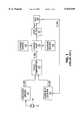
- FIG. 2shows a block diagram of the present invention incorporated into a PLL.
- Self-adjusting controls 209 and 210, and bias check circuits 211 and 212are integrated with the components of a conventional PLL.
- Self-adjusting control 209turns a bias current on by supplying a signal HI -- ON to a current source 105 at regular intervals.
- the regular intervalsare preset, based on the maximum operating frequency of a charge pump 104 and the length of time required for the output current of current source 105 to stabilize.
- a phase comparator 103sends a signal LOCK -- ON to self-adjusting control 209.
- Self-adjusting control 209measures the interval between its assertion of signal HI -- ON and the generation of a signal HI -- BIAS -- OK by bias check circuit 211. This interval represents the time required for the bias current from current source 105 to stabilize after being turned on. The interval is used to generate a signal that turns on current source 105 just long enough before charge pump operation for the bias current to reach steady-state. This optimized control continues until the PLL goes back out of lock, whereupon self-adjusting control 209 resumes the preset regular interval activation of current source 105. In the same manner, self-adjusting control 210 minimizes the time of bias current generation by a current source 106.
- Self-adjusting control 210turns a bias current on by supplying a signal LO -- ON to current source 106 at regular intervals. When the PLL is out of lock, these regular intervals are preset, based on the maximum operating frequency of charge pump 104 and the length of time required for the output of current source 106 to stabilize. Once the PLL is locked, phase comparator 103 sends a signal LOCK -- ON to self-adjusting control 210. Self-adjusting control 210 then measures the interval between its assertion of signal LO -- ON and the generation of a signal LO -- BIAS -- OK by bias check circuit 212. This interval represents the time required for the bias current from current source 106 to stabilize after being turned on.
- the intervalis used to generate a signal that turns on current source 106 just long enough before charge pump operation for the bias current to reach steady-state. This optimized control continues until the PLL goes back out of lock, whereupon self-adjusting control 210 resumes the preset regular interval activation of current source 106. At the completion of each charge pump event, the falling edge of a signal CP -- FBK from charge pump 104 instructs circuits 209 and 210 to turn off bias currents.
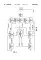
- Both self-adjusting control 209 and self-adjusting control 210can utilize the same basic circuit, an embodiment of which is depicted in FIG. 3.
- a reference oscillator 309generates clock pulses at the input terminal of a divide-by-N countdown counter 310.
- a count C -- COUNT of the number of counts within counter 310is compared with the output of a default register 304.
- Default register 304contains a prespecified count D -- COUNT determined to be the point at which bias current would need to be turned on if charge pump 104 were operating at its maximum possible frequency.
- a comparator 308asserts a signal D -- BIAS -- ON.
- an output logic circuit 306provides signal D -- BIAS -- ON as a signal BIAS -- ON, which turns on a bias current source (not shown).
- phase comparator 103When the PLL goes into a locked state, phase comparator 103 generates signal LOCK -- ON, which resets a counter logic circuit 305 and a stabilization counter 301.
- circuit 305When the PLL goes into a locked state, circuit 305 generates a clock pulse signal COUNT -- ON that clocks stabilization counter 301.
- circuit 305receives a signal BIAS -- OK from a bias checking circuit 311, stabilization counter 301 latches its count value as an output S -- COUNT.
- circuit 305prevents any further counting by counter 301.
- a count T -- COUNT from a tolerance register 302is added to output S -- COUNT by an adder 303, which provides the result as a count A -- COUNT.
- Count T -- COUNTis a predefined constant value that represents a tolerance band to guard against normal variations in bias circuit operation and ensure sufficient time for bias current stabilization prior to charge pump operation.
- Count A -- COUNTdetermines the number of clock pulses to be reached by counter 310 before turning on the bias current source.
- a comparator 307sends a signal A -- BIAS -- ON to output logic circuit 306.
- a signal CNT -- ONCE from circuit 305indicates that output A -- COUNT has been defined, and causes output logic circuit 306 to pass signal A BIAS -- ON as signal BIAS -- ON to turn on the bias current source.
- a binary counter 701is reset to a "00"state by signal LOCK -- ON. This forces the output of a NAND gate 703 into a logic HIGH state.
- the next signal CP -- FBK from charge pump 104 received by an AND gate 702increments counter 701 into a "01"state.
- signal CNT -- ONCEwhich represents the most significant bit of counter 701, provides a logic HIGH output.
- Signal LOCK -- ONalso resets D-type flip-flops 704 and 705. Upon receipt of signal D -- BIAS -- ON, flip-flop 704 produces a logic HIGH output, switching an output signal CNT -- WIN from an XOR gate 706 into a logic HIGH state.
- a three-input AND gate 707produces a signal COUNT -- ON composed of pulses from oscillator 309.
- Signal COUNT -- ONclocks stabilization counter 301.
- flip-flop 705receives signal BIAS -- OK, it asserts a logic HIGH output, forcing signal CNT -- WIN back into a logic LOW state, and blocking any further signal COUNT -- ON from AND gate 707.
- counter 701increments into a "10" state, forcing both signal CNT -- ONCE and the output of NAND gate 703 into logic LOW states. This effectively prevents any further counting activity by stabilization counter 301 until binary counter 701 is reset.
- a D-type flip-flop 710generates an output signal BIAS -- SELECT that selects an output signal MUX -- OUT from a multiplexer 711. While signal BIAS -- SELECT is in a logic LOW state, multiplexer 711 passes signal D -- BIAS -- ON as signal MUX -- OUT. However, when the falling edge of signal CNT -- ONCE triggers flip-flop 710, signal BIAS -- SELECT swings HIGH, causing multiplexer 711 to pass signal A -- BIAS -- ON as signal MUX -- OUT.
- a D-type flip-flop 712provides a logic HIGH output during charge pump operation, allowing an AND gate 713 to provide signal MUX -- OUT as signal BIAS -- ON, to turn on the bias current source.
- the falling edge of signal CP -- FBKtriggers flip-flop 712, forcing signal BIAS -- ON into a logic LOW state and turning off the bias current source.
- signal CP -- FBKto trigger flip-flop 712 ensures that bias current is not shut off until after charge pump operation has been completed. In this manner, one cycle after the PLL becomes locked, bias current on time is reduced to a minimum level.
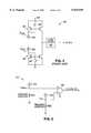
- bias check circuit 212An embodiment of bias check circuit 212 is shown in FIG. 5.
- a checking resistor R501is placed between current source 106 and ground potential. This produces a checking voltage Vcheck at the non-inverting input of a comparator 504.
- a reference current source 505provides a constant current across tracking resistor R502. This provides a positive comparison voltage Vref at the inverting input of comparator 504.
- resistor R502By making resistor R502 very large, only a very small current is required from current source 505, minimizing the power consumption of bias check circuit 212.
- current source 106is off, the non-inverting input of comparator 504 is at ground potential, keeping the output of comparator 504 in a logic LOW state.
- current source 505 and resistor R502are designed such that when current source 106 is providing a constant current, voltage Vcheck at the non-inverting input of comparator 504 is greater than voltage Vref, bringing the output signal LO -- BIAS -- ON to a logic HIGH state.
- a similar circuitcan provide an embodiment of bias check circuit 211, as shown in FIG. 6.
- a checking resistor R601is placed between current source 105 and the circuit power supply voltage Vdd. This produces a checking voltage Vcheck at the inverting input of a comparator 604.
- a reference current source 605pulls a constant current across tracking resistor R602. This provides a positive comparison voltage Vref at the non-inverting input of comparator 604.
- resistor R602By making resistor R602 very large, current source 605 must sink only a very small current, minimizing the power consumption of bias check circuit 211.
- current source 105When current source 105 is off, the inverting input of comparator 604 is at Vdd, keeping the output of comparator 604 in a logic LOW state.
- current source 605 and resistor R602are designed such that when current source 105 is providing a constant current, voltage Vcheck at the inverting input of comparator 604 is greater than voltage Vref, bringing the output signal HI -- BIAS -- ON to a logic HIGH state.
- bias control signalsare indicated, as shown by signals HI -- ON and LO -- ON in FIG. 2, a single signal could be used to turn on both current sources 105 and 106.
- This single signalcould be based on either the longest required interval generated by either self-adjusting control 209 or self-adjusting control 210, or could even be the interval generated by a single self-adjusting control circuit, augmented by a suitable amount of buffering tolerance. In such an implementation, only one self-adjusting control circuit would be required, which would also be the case where the PLL only included one frequency divider.
- divide-by-N counter 310could be implemented as a countup counter with appropriate modifications to the control logic, while both counter logic circuit 305 and output logic circuit 306 could be implemented with combinational, rather than sequential, logic. Furthermore, all comparator circuits could include hysteresis for output signal stabilization. Finally, it should be noted that while a conventional comparator circuit is used in the aforementioned implementations for bias check circuits 211 and 212, a current source plus a compensated zener circuit or bandgap reference could also be utilized.
Landscapes
- Stabilization Of Oscillater, Synchronisation, Frequency Synthesizers (AREA)
Abstract
Description
1 . Field of the Invention
The present invention relates to integrated circuit phase-locked loops, and in particular, to a bias current control circuit for minimization of power consumption.
2 . Discussion of the Related Art
In an integrated circuit, a phase-locked loop, or PLL, is used to track the frequency of an incoming signal and also free the incoming signal from noise. A conventional PLL implementation is shown in FIG. 1. A reference input signal R-- SIG is provided by a stable oscillator such as acrystal oscillator 109 and afrequency divider 101. Signal R-- SIG is made up of clock pulses of frequency fref, which is defined by:
fref =fc /R
where fc is the crystal frequency and R is the division factor offrequency divider 101. Concurrently, voltage-controlled oscillator aVCO 108 sends a frequency divider 102 a signal V-- SIG made up of clock pulses of frequency fvco.Frequency divider 102, having a division factor of N, generates a signal N-- SIG having a frequency fN, which is defined by:
fN =fvco /N
Aphase comparator 103 compares the relative timing of signal R-- SIG and signal N-- SIG, and outputs an error signal P-- SIG based on their phase and frequency difference. Signal P-- SIG causes acharge pump 104 to generate pulses that both sink and source current.Current sources charge pump 104 with bias currents required for proper pulse generation. These pulses charge or discharge aloop filter 107, which consequently produces an output voltage Vref. Voltage Vref is applied toVCO 108, which adjustsVCO 108's frequency accordingly. In this manner, fN is adjusted to match fref.
The use of a current source in combination with a current mirror provides an accurate, rapid-switching output that can be applied to multiple locations. However, the bias currents required for such a configuration can unnecessarily dissipate power in the circuit. As can be seen in FIG. 4,current mirrors switches switches current sources
Ac cordingly, it is desirable to provide a bias control circuit that is capable of minimizing bias circuit power consumption by turning on bias currents only when required by charge pump activity.
The present invention provides, in an integrated circuit that includes a frequency divider and a charge pump as part of a phase-locked loop (PLL), a circuit for turning on a charge pump bias current only when required by the charge pump. According to the present invention, the circuit for controlling the bias current includes: (i) a bias checking circuit for indicating when the bias current has stabilized; (ii) a default control circuit to turn on the bias current at prespecified intervals when the PLL is out of lock; and (iii) a self-adjusting control circuit that operates when the PLL is locked, to measure how long the bias current takes to stabilize after being turned on, and then turn on the bias current that amount of time before actual charge pump operation occurs.
In an embodiment of the present invention, the bias checking circuit includes a checking resistor to produce a bias checking voltage, and a reference current source and a tracking resistor to produce a reference voltage. A comparator is used to generate a signal indicating bias current stabilization when the bias voltage reaches the reference voltage. The circuit further includes hysteresis to eliminate potential multiple triggering.
In another embodiment of the present invention, the self-adjusting control circuit further includes: (i) a stabilization counter for measuring the length of time required for the bias current to stabilize; (ii) an adder to add a predefined amount to the count measured by the stabilization counter in order to provide tolerance for slight variations during actual operation; and (iii) a comparator to generate a signal to turn on the bias current when the count in the frequency divider in the PLL reaches the count produced by the adder.
The present invention provides a circuit that minimizes PLL power consumption. When the PLL is locked, the self-adjusting control circuit turns on the bias current only when required by the charge pump. When the PLL is running out of lock, the input frequencies can be changing every charge pump cycle, making the self-adjusting control circuit unfeasible. Accordingly, at that point, bias current activation control is transferred to the default control circuit. While the PLL is out of lock, the default control circuit reduces wasted power by turning on the bias current only when it would be required were the charge pump operating at maximum frequency. When the PLL locks on the input signal again, the self-adjusting control circuit minimizes power dissipation by re-adjusting the bias current activation intervals based on the application-specific charge pump operating frequency.
The present invention will be better understood upon consideration of the accompanying drawings and the detailed description below.
FIG. 1 shows, in the prior art, a conventional PLL;
FIG. 2 shows a PLL incorporating self-adjusting bias control;
FIG. 3 shows an embodiment of the present invention;
FIG. 4 shows, in the prior art, a schematic model of a conventional charge pump and loop filter circuit in a PLL;
FIG. 5 shows an embodiment of a bias check circuit;
FIG. 6 shows another embodiment of a bias check circuit;
FIG. 7a shows an implementation of a counter logic circuit;
FIG. 7b shows an implementation of an output logic circuit.
Use of the same reference numbers in different figures indicates similar or like elements.
The present invention reduces power consumption in a charge pump circuit of a PLL by turning on the bias currents only when required by the charge pump. FIG. 2 shows a block diagram of the present invention incorporated into a PLL. Self-adjustingcontrols 209 and 210, andbias check circuits control 209 turns a bias current on by supplying a signal HI-- ON to acurrent source 105 at regular intervals. When the PLL is out of lock, the regular intervals are preset, based on the maximum operating frequency of acharge pump 104 and the length of time required for the output current ofcurrent source 105 to stabilize. When the PLL is locked, aphase comparator 103 sends a signal LOCK-- ON to self-adjustingcontrol 209. Self-adjustingcontrol 209 then measures the interval between its assertion of signal HI-- ON and the generation of a signal HI-- BIAS-- OK bybias check circuit 211. This interval represents the time required for the bias current fromcurrent source 105 to stabilize after being turned on. The interval is used to generate a signal that turns oncurrent source 105 just long enough before charge pump operation for the bias current to reach steady-state. This optimized control continues until the PLL goes back out of lock, whereupon self-adjustingcontrol 209 resumes the preset regular interval activation ofcurrent source 105. In the same manner, self-adjusting control 210 minimizes the time of bias current generation by acurrent source 106. Self-adjusting control 210 turns a bias current on by supplying a signal LO-- ON tocurrent source 106 at regular intervals. When the PLL is out of lock, these regular intervals are preset, based on the maximum operating frequency ofcharge pump 104 and the length of time required for the output ofcurrent source 106 to stabilize. Once the PLL is locked,phase comparator 103 sends a signal LOCK-- ON to self-adjusting control 210. Self-adjusting control 210 then measures the interval between its assertion of signal LO-- ON and the generation of a signal LO-- BIAS-- OK bybias check circuit 212. This interval represents the time required for the bias current fromcurrent source 106 to stabilize after being turned on. The interval is used to generate a signal that turns oncurrent source 106 just long enough before charge pump operation for the bias current to reach steady-state. This optimized control continues until the PLL goes back out of lock, whereupon self-adjusting control 210 resumes the preset regular interval activation ofcurrent source 106. At the completion of each charge pump event, the falling edge of a signal CP-- FBK fromcharge pump 104 instructscircuits 209 and 210 to turn off bias currents.
Both self-adjustingcontrol 209 and self-adjusting control 210 can utilize the same basic circuit, an embodiment of which is depicted in FIG. 3. Areference oscillator 309 generates clock pulses at the input terminal of a divide-by-N countdown counter 310. A count C-- COUNT of the number of counts withincounter 310 is compared with the output of adefault register 304.Default register 304 contains a prespecified count D-- COUNT determined to be the point at which bias current would need to be turned on ifcharge pump 104 were operating at its maximum possible frequency. When count C-- COUNT reaches count D-- COUNT, acomparator 308 asserts a signal D-- BIAS-- ON. While the PLL is out of lock, anoutput logic circuit 306 provides signal D-- BIAS-- ON as a signal BIAS-- ON, which turns on a bias current source (not shown). When the PLL goes into a locked state,phase comparator 103 generates signal LOCK-- ON, which resets acounter logic circuit 305 and astabilization counter 301. The next time signal D-- BIAS-- ON is asserted,circuit 305 generates a clock pulse signal COUNT-- ON that clocksstabilization counter 301. Whencircuit 305 receives a signal BIAS-- OK from abias checking circuit 311,stabilization counter 301 latches its count value as an output S-- COUNT. Until it is reset by the next signal LOCK-- ON,circuit 305 prevents any further counting bycounter 301. A count T-- COUNT from atolerance register 302 is added to output S-- COUNT by anadder 303, which provides the result as a count A-- COUNT. Count T-- COUNT is a predefined constant value that represents a tolerance band to guard against normal variations in bias circuit operation and ensure sufficient time for bias current stabilization prior to charge pump operation. Count A-- COUNT determines the number of clock pulses to be reached bycounter 310 before turning on the bias current source. When count C-- COUNT reaches count A-- COUNT, acomparator 307 sends a signal A-- BIAS-- ON tooutput logic circuit 306. A signal CNT-- ONCE fromcircuit 305 indicates that output A-- COUNT has been defined, and causesoutput logic circuit 306 to pass signal A BIAS-- ON as signal BIAS-- ON to turn on the bias current source.
An implementation ofcounter logic circuit 305 is shown in FIG. 7a. Abinary counter 701 is reset to a "00"state by signal LOCK-- ON. This forces the output of aNAND gate 703 into a logic HIGH state. The next signal CP-- FBK fromcharge pump 104 received by an ANDgate 702 increments counter 701 into a "01"state. As a result, signal CNT-- ONCE, which represents the most significant bit ofcounter 701, provides a logic HIGH output. Signal LOCK-- ON also resets D-type flip-flops flop 704 produces a logic HIGH output, switching an output signal CNT-- WIN from anXOR gate 706 into a logic HIGH state. When signals CNT-- ONCE and CNT-- WIN are both in logic HIGH states, a three-input ANDgate 707 produces a signal COUNT-- ON composed of pulses fromoscillator 309. Signal COUNT-- ON clocksstabilization counter 301. When flip-flop 705 receives signal BIAS-- OK, it asserts a logic HIGH output, forcing signal CNT-- WIN back into a logic LOW state, and blocking any further signal COUNT-- ON from ANDgate 707. At the next signal CP-- FBK, counter 701 increments into a "10" state, forcing both signal CNT-- ONCE and the output ofNAND gate 703 into logic LOW states. This effectively prevents any further counting activity bystabilization counter 301 untilbinary counter 701 is reset.
An implementation ofoutput logic circuit 306 is shown in FIG. 7b. A D-type flip-flop 710 generates an output signal BIAS-- SELECT that selects an output signal MUX-- OUT from amultiplexer 711. While signal BIAS-- SELECT is in a logic LOW state, multiplexer 711 passes signal D-- BIAS-- ON as signal MUX-- OUT. However, when the falling edge of signal CNT-- ONCE triggers flip-flop 710, signal BIAS-- SELECT swings HIGH, causingmultiplexer 711 to pass signal A-- BIAS-- ON as signal MUX-- OUT. A D-type flip-flop 712 provides a logic HIGH output during charge pump operation, allowing an ANDgate 713 to provide signal MUX-- OUT as signal BIAS-- ON, to turn on the bias current source. However, after the charge pump event, the falling edge of signal CP-- FBK triggers flip-flop 712, forcing signal BIAS-- ON into a logic LOW state and turning off the bias current source. Using signal CP-- FBK to trigger flip-flop 712 ensures that bias current is not shut off until after charge pump operation has been completed. In this manner, one cycle after the PLL becomes locked, bias current on time is reduced to a minimum level. When the PLL goes out of lock, the falling edge of signal LOCK-- ON resets flip-flop 710, switching the output ofmultiplexer 711 back to signal D-- BIAS-- ON and returning bias current activation timing to the constant interval preset indefault register 304.
In this scheme for self-adjusting bias current control, proper detection of bias current stabilization is important. An embodiment ofbias check circuit 212 is shown in FIG. 5. A checking resistor R501 is placed betweencurrent source 106 and ground potential. This produces a checking voltage Vcheck at the non-inverting input of acomparator 504. A referencecurrent source 505 provides a constant current across tracking resistor R502. This provides a positive comparison voltage Vref at the inverting input ofcomparator 504. By making resistor R502 very large, only a very small current is required fromcurrent source 505, minimizing the power consumption ofbias check circuit 212. Whencurrent source 106 is off, the non-inverting input ofcomparator 504 is at ground potential, keeping the output ofcomparator 504 in a logic LOW state. However,current source 505 and resistor R502 are designed such that whencurrent source 106 is providing a constant current, voltage Vcheck at the non-inverting input ofcomparator 504 is greater than voltage Vref, bringing the output signal LO-- BIAS-- ON to a logic HIGH state. A similar circuit can provide an embodiment ofbias check circuit 211, as shown in FIG. 6. A checking resistor R601 is placed betweencurrent source 105 and the circuit power supply voltage Vdd. This produces a checking voltage Vcheck at the inverting input of acomparator 604. A referencecurrent source 605 pulls a constant current across tracking resistor R602. This provides a positive comparison voltage Vref at the non-inverting input ofcomparator 604. By making resistor R602 very large,current source 605 must sink only a very small current, minimizing the power consumption ofbias check circuit 211. Whencurrent source 105 is off, the inverting input ofcomparator 604 is at Vdd, keeping the output ofcomparator 604 in a logic LOW state. However,current source 605 and resistor R602 are designed such that whencurrent source 105 is providing a constant current, voltage Vcheck at the inverting input ofcomparator 604 is greater than voltage Vref, bringing the output signal HI-- BIAS-- ON to a logic HIGH state.
The above detailed description is provided to illustrate the specific embodiments of the present invention, and is not intended to be limiting. Numerous variations and modifications within the present invention will be apparent to one skilled in the art. For example, although separate bias control signals are indicated, as shown by signals HI-- ON and LO-- ON in FIG. 2, a single signal could be used to turn on bothcurrent sources control 209 or self-adjusting control 210, or could even be the interval generated by a single self-adjusting control circuit, augmented by a suitable amount of buffering tolerance. In such an implementation, only one self-adjusting control circuit would be required, which would also be the case where the PLL only included one frequency divider. Also, divide-by-N counter 310 could be implemented as a countup counter with appropriate modifications to the control logic, while both counterlogic circuit 305 andoutput logic circuit 306 could be implemented with combinational, rather than sequential, logic. Furthermore, all comparator circuits could include hysteresis for output signal stabilization. Finally, it should be noted that while a conventional comparator circuit is used in the aforementioned implementations forbias check circuits
Claims (11)
1. In an integrated circuit phase-locked loop (PLL) including a divide-by-N counter, a phase comparator, a voltage-controlled oscillator, and a charge pump having a bias current source, a bias control circuit comprising:
a bias checking circuit for indicating when said bias current source in said charge pump has stabilized; and
a bias activation circuit to control the operation of said bias current source.
2. The circuit of claim 1 wherein said bias activation circuit includes:
a default control circuit for activating said bias current for a predefined interval sufficient to ensure proper operation of said charge pump at all operating frequencies; and
a self-adjusting control circuit for, when said PLL is locked, activating said bias current only as required for proper operation of said charge pump.
3. The circuit of claim 2 wherein said self-adjusting control circuit comprises a self-adjusting logic circuit to turn on said bias current source a calculated lead count of input clock pulses before operation of said charge pump, wherein said lead count is the number of input clock pulses required for said bias current source to stabilize plus a predetermined tolerance count of input clock pulses to accommodate slight operational variations.
4. The circuit of claim 3 wherein said default control circuit comprises a default logic circuit to turn on said bias current source a predefined default count of input clock pulses before operation of said charge pump, whenever said PLL is out of lock or said lead count is unavailable.
5. The circuit of claim 4 wherein said self-adjusting logic circuit comprises:
a stabilization counter for measuring a stabilization count of input clock pulses required for said bias current source to stabilize after being turned on;
an adder for combining said stabilization count with said tolerance count to generate said lead count;
a comparator that asserts an optimized signal for turning on said bias current source when a total count of input clock pulses received by said divide-by-N counter reaches said lead count.
6. The circuit of claim 5 wherein said default logic circuit comprises:
a default register for storing said default count; and
a default comparator for asserting a default signal for turning on said bias current source when said total count reaches said default count.
7. The circuit of claim 6 wherein said bias activation circuit further comprises an output logic circuit to provide said optimized signal as a bias activation signal to turn on said bias current source when said PLL is locked, and provide said default signal as said bias activation signal when said PLL is out of lock or said lead count is unavailable.
8. The circuit of claim 7 wherein said output logic circuit comprises:
a multiplexer to select between said optimized signal and said default signal; and
a termination logic circuit to turn off said bias current source at the completion of the activity of said charge pump.
9. The circuit of claim 1 wherein said bias checking circuit comprises:
a comparator;
a checking resistor coupled to said bias current source;
a tracking resistor; and
a reference current source coupled to said tracking resistor, said reference current source generating a reference current that generates a reference voltage drop across said tracking resistor that is substantially equal to a checking voltage that exists across said checking resistor when the steady-state output current of said bias current source is applied across said checking resistor;
wherein the inverting and non-inverting terminals of said comparator are coupled to either the junction of said reference current source and said tracking resistor, or the junction of said bias current source and said checking resistor, with the inverting terminal of said comparator being coupled to the junction that is at higher potential of the two when said bias current source is off, and the non-inverting terminal of said comparator being coupled to the other junction.
10. The circuit of claim 9 wherein the resistance of said tracking resistor is substantially greater than the resistance of said checking resistor.
11. A method for controlling the activation of a bias current in a PLL having a charge pump and bias circuit in order to reduce power consumption in said PLL comprising the steps of:
(i) when said PLL is locked:
measuring the time required for said bias current to stabilize after being turned on;
turning on said bias current just long enough before the operation of said charge pump to allow said bias current to stabilize;
(ii) when said PLL is out of lock:
turning on said bias current for the minimum time that would be required if the charge pump were operating at maximum frequency.
Priority Applications (1)
| Application Number | Priority Date | Filing Date | Title |
|---|---|---|---|
| US09/042,589US5939949A (en) | 1998-03-16 | 1998-03-16 | Self-adjusting startup control for charge pump current source in phase locked loop |
Applications Claiming Priority (1)
| Application Number | Priority Date | Filing Date | Title |
|---|---|---|---|
| US09/042,589US5939949A (en) | 1998-03-16 | 1998-03-16 | Self-adjusting startup control for charge pump current source in phase locked loop |
Publications (1)
| Publication Number | Publication Date |
|---|---|
| US5939949Atrue US5939949A (en) | 1999-08-17 |
Family
ID=21922725
Family Applications (1)
| Application Number | Title | Priority Date | Filing Date |
|---|---|---|---|
| US09/042,589Expired - LifetimeUS5939949A (en) | 1998-03-16 | 1998-03-16 | Self-adjusting startup control for charge pump current source in phase locked loop |
Country Status (1)
| Country | Link |
|---|---|
| US (1) | US5939949A (en) |
Cited By (63)
| Publication number | Priority date | Publication date | Assignee | Title |
|---|---|---|---|---|
| US6278304B1 (en)* | 2000-03-23 | 2001-08-21 | International Business Machines Corporation | Look-ahead enabling charge pump in phase-locked loop circuits |
| US6608472B1 (en) | 2000-10-26 | 2003-08-19 | Cypress Semiconductor Corporation | Band-gap reference circuit for providing an accurate reference voltage compensated for process state, process variations and temperature |
| US6614316B2 (en)* | 2001-04-05 | 2003-09-02 | International Business Machines Corporation | Fractional integration and proportional multiplier control to achieve desired loop dynamics |
| US6646512B2 (en)* | 2000-12-06 | 2003-11-11 | Ati International, Srl | Self-bias and differential structure based PLL with fast lockup circuit and current range calibration for process variation |
| US6734708B1 (en)* | 1999-07-23 | 2004-05-11 | Infineon Technologies Ag | Controllable current source circuit and a phase locked loop equipped with such a circuit |
| RU2235421C2 (en)* | 1999-09-21 | 2004-08-27 | Фудзитсу Дженерал Лимитед | Phase-locked loop frequency control circuit |
| US20040169537A1 (en)* | 2003-02-28 | 2004-09-02 | Ati Technologies, Inc. | Gain control circuitry for delay locked loop circuit |
| US20040169563A1 (en)* | 2003-02-28 | 2004-09-02 | Saeed Abbasi | System for phase locked loop operation and method thereof |
| US6798299B1 (en)* | 2000-10-26 | 2004-09-28 | Cypress Semiconductor Corporation | Crystal-less oscillator circuit with trimmable analog current control for increased stability |
| RU2239282C1 (en)* | 2003-04-01 | 2004-10-27 | Федеральное государственное унитарное предприятие "Конструкторское бюро "Луч" | Method for tuning broadband pll frequency synthesizer |
| US6829190B1 (en) | 2002-06-13 | 2004-12-07 | Cypress Semiconductor Corporation | Method and system for programming a memory device |
| RU2255418C2 (en)* | 2000-01-10 | 2005-06-27 | Дженерал Электрик Компани | Method and device for improving locking and synchronization characteristics for phase-locked loops |
| US6911868B1 (en)* | 2001-11-06 | 2005-06-28 | National Semiconductor Corporation | Phase-locked loop frequency synthesizer using automatic loop control and method of operation |
| RU2267860C2 (en)* | 2003-09-01 | 2006-01-10 | Корпорация "Самсунг Электроникс" | Frequencies synthesizer with alternating amplification and pass band of phase auto-adjustment ring |
| US20060017477A1 (en)* | 2004-07-26 | 2006-01-26 | Kazuhiko Miki | Systems and methods for initializing plls and measuring vco characteristics |
| US20060036973A1 (en)* | 2004-08-13 | 2006-02-16 | Kenneth Ogami | Method and an apparatus to design a processing system using a graphical user interface |
| US7005933B1 (en) | 2000-10-26 | 2006-02-28 | Cypress Semiconductor Corporation | Dual mode relaxation oscillator generating a clock signal operating at a frequency substantially same in both first and second power modes |
| US20070024331A1 (en)* | 2005-07-29 | 2007-02-01 | Feng Lin | Bias generator with feedback control |
| US7301316B1 (en) | 2005-08-12 | 2007-11-27 | Altera Corporation | Stable DC current source with common-source output stage |
| WO2008097718A1 (en)* | 2007-02-08 | 2008-08-14 | Motorola, Inc. | Automatic bias adjustment for phase-locked loop charge pump |
| US20090267697A1 (en)* | 2007-03-29 | 2009-10-29 | Scientific Components Corporation | Frequency synthesizer using a phase-locked loop and single side band mixer |
| RU2384941C2 (en)* | 2008-03-31 | 2010-03-20 | Открытое акционерное общество "Российская корпорация ракетно-космического приборостроения и информационных систем" (ОАО "Российские космические системы") | Device for determining lock-on of phase-locked loop system |
| US7737724B2 (en) | 2007-04-17 | 2010-06-15 | Cypress Semiconductor Corporation | Universal digital block interconnection and channel routing |
| US7761845B1 (en) | 2002-09-09 | 2010-07-20 | Cypress Semiconductor Corporation | Method for parameterizing a user module |
| US7765095B1 (en) | 2000-10-26 | 2010-07-27 | Cypress Semiconductor Corporation | Conditional branching in an in-circuit emulation system |
| US7770113B1 (en) | 2001-11-19 | 2010-08-03 | Cypress Semiconductor Corporation | System and method for dynamically generating a configuration datasheet |
| US7774190B1 (en) | 2001-11-19 | 2010-08-10 | Cypress Semiconductor Corporation | Sleep and stall in an in-circuit emulation system |
| US7825688B1 (en) | 2000-10-26 | 2010-11-02 | Cypress Semiconductor Corporation | Programmable microcontroller architecture(mixed analog/digital) |
| US7844437B1 (en) | 2001-11-19 | 2010-11-30 | Cypress Semiconductor Corporation | System and method for performing next placements and pruning of disallowed placements for programming an integrated circuit |
| US7893724B2 (en) | 2004-03-25 | 2011-02-22 | Cypress Semiconductor Corporation | Method and circuit for rapid alignment of signals |
| US8026739B2 (en) | 2007-04-17 | 2011-09-27 | Cypress Semiconductor Corporation | System level interconnect with programmable switching |
| US8035455B1 (en) | 2005-12-21 | 2011-10-11 | Cypress Semiconductor Corporation | Oscillator amplitude control network |
| US8042093B1 (en) | 2001-11-15 | 2011-10-18 | Cypress Semiconductor Corporation | System providing automatic source code generation for personalization and parameterization of user modules |
| US8040266B2 (en) | 2007-04-17 | 2011-10-18 | Cypress Semiconductor Corporation | Programmable sigma-delta analog-to-digital converter |
| US8049569B1 (en) | 2007-09-05 | 2011-11-01 | Cypress Semiconductor Corporation | Circuit and method for improving the accuracy of a crystal-less oscillator having dual-frequency modes |
| US20110283057A1 (en)* | 2000-10-26 | 2011-11-17 | Cypress Semiconductor Corporation | Microcontroller Programmable System on a Chip |
| US8069428B1 (en) | 2001-10-24 | 2011-11-29 | Cypress Semiconductor Corporation | Techniques for generating microcontroller configuration information |
| US8067948B2 (en) | 2006-03-27 | 2011-11-29 | Cypress Semiconductor Corporation | Input/output multiplexer bus |
| US8069405B1 (en) | 2001-11-19 | 2011-11-29 | Cypress Semiconductor Corporation | User interface for efficiently browsing an electronic document using data-driven tabs |
| US8069436B2 (en) | 2004-08-13 | 2011-11-29 | Cypress Semiconductor Corporation | Providing hardware independence to automate code generation of processing device firmware |
| US8078970B1 (en) | 2001-11-09 | 2011-12-13 | Cypress Semiconductor Corporation | Graphical user interface with user-selectable list-box |
| US8078894B1 (en) | 2007-04-25 | 2011-12-13 | Cypress Semiconductor Corporation | Power management architecture, method and configuration system |
| US8085100B2 (en) | 2005-02-04 | 2011-12-27 | Cypress Semiconductor Corporation | Poly-phase frequency synthesis oscillator |
| US8085067B1 (en) | 2005-12-21 | 2011-12-27 | Cypress Semiconductor Corporation | Differential-to-single ended signal converter circuit and method |
| US8089461B2 (en) | 2005-06-23 | 2012-01-03 | Cypress Semiconductor Corporation | Touch wake for electronic devices |
| US8092083B2 (en) | 2007-04-17 | 2012-01-10 | Cypress Semiconductor Corporation | Temperature sensor with digital bandgap |
| US8103496B1 (en) | 2000-10-26 | 2012-01-24 | Cypress Semicondutor Corporation | Breakpoint control in an in-circuit emulation system |
| US8103497B1 (en) | 2002-03-28 | 2012-01-24 | Cypress Semiconductor Corporation | External interface for event architecture |
| US8120408B1 (en) | 2005-05-05 | 2012-02-21 | Cypress Semiconductor Corporation | Voltage controlled oscillator delay cell and method |
| US8130025B2 (en) | 2007-04-17 | 2012-03-06 | Cypress Semiconductor Corporation | Numerical band gap |
| US8149048B1 (en) | 2000-10-26 | 2012-04-03 | Cypress Semiconductor Corporation | Apparatus and method for programmable power management in a programmable analog circuit block |
| US8160864B1 (en) | 2000-10-26 | 2012-04-17 | Cypress Semiconductor Corporation | In-circuit emulator and pod synchronized boot |
| US8286125B2 (en) | 2004-08-13 | 2012-10-09 | Cypress Semiconductor Corporation | Model for a hardware device-independent method of defining embedded firmware for programmable systems |
| US8316245B1 (en)* | 2008-12-11 | 2012-11-20 | Integrated Device Technology, Inc. | Method and apparatus for fail-safe start-up circuit for subthreshold current sources |
| CN102832807A (en)* | 2012-08-31 | 2012-12-19 | 电子科技大学 | Current control circuit for charge pump |
| US8402313B1 (en) | 2002-05-01 | 2013-03-19 | Cypress Semiconductor Corporation | Reconfigurable testing system and method |
| US8499270B1 (en) | 2007-04-25 | 2013-07-30 | Cypress Semiconductor Corporation | Configuration of programmable IC design elements |
| US8516025B2 (en) | 2007-04-17 | 2013-08-20 | Cypress Semiconductor Corporation | Clock driven dynamic datapath chaining |
| US8533677B1 (en) | 2001-11-19 | 2013-09-10 | Cypress Semiconductor Corporation | Graphical user interface for dynamically reconfiguring a programmable device |
| US9448964B2 (en) | 2009-05-04 | 2016-09-20 | Cypress Semiconductor Corporation | Autonomous control in a programmable system |
| US9564902B2 (en) | 2007-04-17 | 2017-02-07 | Cypress Semiconductor Corporation | Dynamically configurable and re-configurable data path |
| US9720805B1 (en) | 2007-04-25 | 2017-08-01 | Cypress Semiconductor Corporation | System and method for controlling a target device |
| USRE47715E1 (en) | 2003-12-11 | 2019-11-05 | Conversant Intellectual Property Management Inc. | Charge pump for PLL/DLL |
Citations (3)
| Publication number | Priority date | Publication date | Assignee | Title |
|---|---|---|---|---|
| US5764108A (en)* | 1996-10-09 | 1998-06-09 | National Semiconductor Corporation | Apparatus for reducing power consumption of device controlled by counter and noise due to counter reload |
| US5783972A (en)* | 1995-11-29 | 1998-07-21 | Nec Corporation | Power saving PLL circuit |
| US5847614A (en)* | 1996-11-15 | 1998-12-08 | Analog Devices, Inc. | Low power charge pump |
- 1998
- 1998-03-16USUS09/042,589patent/US5939949A/ennot_activeExpired - Lifetime
Patent Citations (3)
| Publication number | Priority date | Publication date | Assignee | Title |
|---|---|---|---|---|
| US5783972A (en)* | 1995-11-29 | 1998-07-21 | Nec Corporation | Power saving PLL circuit |
| US5764108A (en)* | 1996-10-09 | 1998-06-09 | National Semiconductor Corporation | Apparatus for reducing power consumption of device controlled by counter and noise due to counter reload |
| US5847614A (en)* | 1996-11-15 | 1998-12-08 | Analog Devices, Inc. | Low power charge pump |
Cited By (94)
| Publication number | Priority date | Publication date | Assignee | Title |
|---|---|---|---|---|
| US6734708B1 (en)* | 1999-07-23 | 2004-05-11 | Infineon Technologies Ag | Controllable current source circuit and a phase locked loop equipped with such a circuit |
| RU2235421C2 (en)* | 1999-09-21 | 2004-08-27 | Фудзитсу Дженерал Лимитед | Phase-locked loop frequency control circuit |
| RU2255418C2 (en)* | 2000-01-10 | 2005-06-27 | Дженерал Электрик Компани | Method and device for improving locking and synchronization characteristics for phase-locked loops |
| US6278304B1 (en)* | 2000-03-23 | 2001-08-21 | International Business Machines Corporation | Look-ahead enabling charge pump in phase-locked loop circuits |
| US9766650B2 (en) | 2000-10-26 | 2017-09-19 | Cypress Semiconductor Corporation | Microcontroller programmable system on a chip with programmable interconnect |
| US7005933B1 (en) | 2000-10-26 | 2006-02-28 | Cypress Semiconductor Corporation | Dual mode relaxation oscillator generating a clock signal operating at a frequency substantially same in both first and second power modes |
| US8736303B2 (en) | 2000-10-26 | 2014-05-27 | Cypress Semiconductor Corporation | PSOC architecture |
| US8103496B1 (en) | 2000-10-26 | 2012-01-24 | Cypress Semicondutor Corporation | Breakpoint control in an in-circuit emulation system |
| US6798299B1 (en)* | 2000-10-26 | 2004-09-28 | Cypress Semiconductor Corporation | Crystal-less oscillator circuit with trimmable analog current control for increased stability |
| US10248604B2 (en) | 2000-10-26 | 2019-04-02 | Cypress Semiconductor Corporation | Microcontroller programmable system on a chip |
| US20110283057A1 (en)* | 2000-10-26 | 2011-11-17 | Cypress Semiconductor Corporation | Microcontroller Programmable System on a Chip |
| US9286254B2 (en) | 2000-10-26 | 2016-03-15 | Cypress Semiconductor Corporation | Microcontroller programmable system on a chip with programmable interconnect |
| US7765095B1 (en) | 2000-10-26 | 2010-07-27 | Cypress Semiconductor Corporation | Conditional branching in an in-circuit emulation system |
| US8149048B1 (en) | 2000-10-26 | 2012-04-03 | Cypress Semiconductor Corporation | Apparatus and method for programmable power management in a programmable analog circuit block |
| US10261932B2 (en) | 2000-10-26 | 2019-04-16 | Cypress Semiconductor Corporation | Microcontroller programmable system on a chip |
| US9843327B1 (en) | 2000-10-26 | 2017-12-12 | Cypress Semiconductor Corporation | PSOC architecture |
| US10020810B2 (en) | 2000-10-26 | 2018-07-10 | Cypress Semiconductor Corporation | PSoC architecture |
| US10725954B2 (en) | 2000-10-26 | 2020-07-28 | Monterey Research, Llc | Microcontroller programmable system on a chip |
| US7825688B1 (en) | 2000-10-26 | 2010-11-02 | Cypress Semiconductor Corporation | Programmable microcontroller architecture(mixed analog/digital) |
| US8358150B1 (en) | 2000-10-26 | 2013-01-22 | Cypress Semiconductor Corporation | Programmable microcontroller architecture(mixed analog/digital) |
| US8555032B2 (en)* | 2000-10-26 | 2013-10-08 | Cypress Semiconductor Corporation | Microcontroller programmable system on a chip with programmable interconnect |
| US8176296B2 (en) | 2000-10-26 | 2012-05-08 | Cypress Semiconductor Corporation | Programmable microcontroller architecture |
| US8160864B1 (en) | 2000-10-26 | 2012-04-17 | Cypress Semiconductor Corporation | In-circuit emulator and pod synchronized boot |
| US6608472B1 (en) | 2000-10-26 | 2003-08-19 | Cypress Semiconductor Corporation | Band-gap reference circuit for providing an accurate reference voltage compensated for process state, process variations and temperature |
| US6646512B2 (en)* | 2000-12-06 | 2003-11-11 | Ati International, Srl | Self-bias and differential structure based PLL with fast lockup circuit and current range calibration for process variation |
| US6614316B2 (en)* | 2001-04-05 | 2003-09-02 | International Business Machines Corporation | Fractional integration and proportional multiplier control to achieve desired loop dynamics |
| US8793635B1 (en) | 2001-10-24 | 2014-07-29 | Cypress Semiconductor Corporation | Techniques for generating microcontroller configuration information |
| US8069428B1 (en) | 2001-10-24 | 2011-11-29 | Cypress Semiconductor Corporation | Techniques for generating microcontroller configuration information |
| US10466980B2 (en) | 2001-10-24 | 2019-11-05 | Cypress Semiconductor Corporation | Techniques for generating microcontroller configuration information |
| US6911868B1 (en)* | 2001-11-06 | 2005-06-28 | National Semiconductor Corporation | Phase-locked loop frequency synthesizer using automatic loop control and method of operation |
| US8078970B1 (en) | 2001-11-09 | 2011-12-13 | Cypress Semiconductor Corporation | Graphical user interface with user-selectable list-box |
| US8042093B1 (en) | 2001-11-15 | 2011-10-18 | Cypress Semiconductor Corporation | System providing automatic source code generation for personalization and parameterization of user modules |
| US10698662B2 (en) | 2001-11-15 | 2020-06-30 | Cypress Semiconductor Corporation | System providing automatic source code generation for personalization and parameterization of user modules |
| US8533677B1 (en) | 2001-11-19 | 2013-09-10 | Cypress Semiconductor Corporation | Graphical user interface for dynamically reconfiguring a programmable device |
| US7844437B1 (en) | 2001-11-19 | 2010-11-30 | Cypress Semiconductor Corporation | System and method for performing next placements and pruning of disallowed placements for programming an integrated circuit |
| US8069405B1 (en) | 2001-11-19 | 2011-11-29 | Cypress Semiconductor Corporation | User interface for efficiently browsing an electronic document using data-driven tabs |
| US8370791B2 (en) | 2001-11-19 | 2013-02-05 | Cypress Semiconductor Corporation | System and method for performing next placements and pruning of disallowed placements for programming an integrated circuit |
| US7770113B1 (en) | 2001-11-19 | 2010-08-03 | Cypress Semiconductor Corporation | System and method for dynamically generating a configuration datasheet |
| US7774190B1 (en) | 2001-11-19 | 2010-08-10 | Cypress Semiconductor Corporation | Sleep and stall in an in-circuit emulation system |
| US8103497B1 (en) | 2002-03-28 | 2012-01-24 | Cypress Semiconductor Corporation | External interface for event architecture |
| US8402313B1 (en) | 2002-05-01 | 2013-03-19 | Cypress Semiconductor Corporation | Reconfigurable testing system and method |
| US6829190B1 (en) | 2002-06-13 | 2004-12-07 | Cypress Semiconductor Corporation | Method and system for programming a memory device |
| US7761845B1 (en) | 2002-09-09 | 2010-07-20 | Cypress Semiconductor Corporation | Method for parameterizing a user module |
| US20040169563A1 (en)* | 2003-02-28 | 2004-09-02 | Saeed Abbasi | System for phase locked loop operation and method thereof |
| US6903586B2 (en) | 2003-02-28 | 2005-06-07 | Ati Technologies, Inc. | Gain control circuitry for delay locked loop circuit |
| US20040169537A1 (en)* | 2003-02-28 | 2004-09-02 | Ati Technologies, Inc. | Gain control circuitry for delay locked loop circuit |
| RU2239282C1 (en)* | 2003-04-01 | 2004-10-27 | Федеральное государственное унитарное предприятие "Конструкторское бюро "Луч" | Method for tuning broadband pll frequency synthesizer |
| RU2267860C2 (en)* | 2003-09-01 | 2006-01-10 | Корпорация "Самсунг Электроникс" | Frequencies synthesizer with alternating amplification and pass band of phase auto-adjustment ring |
| USRE47715E1 (en) | 2003-12-11 | 2019-11-05 | Conversant Intellectual Property Management Inc. | Charge pump for PLL/DLL |
| US7893724B2 (en) | 2004-03-25 | 2011-02-22 | Cypress Semiconductor Corporation | Method and circuit for rapid alignment of signals |
| US7019572B2 (en)* | 2004-07-26 | 2006-03-28 | Kabushiki Kaisha Toshiba | Systems and methods for initializing PLLs and measuring VCO characteristics |
| US20060017477A1 (en)* | 2004-07-26 | 2006-01-26 | Kazuhiko Miki | Systems and methods for initializing plls and measuring vco characteristics |
| US8286125B2 (en) | 2004-08-13 | 2012-10-09 | Cypress Semiconductor Corporation | Model for a hardware device-independent method of defining embedded firmware for programmable systems |
| US8082531B2 (en) | 2004-08-13 | 2011-12-20 | Cypress Semiconductor Corporation | Method and an apparatus to design a processing system using a graphical user interface |
| US8069436B2 (en) | 2004-08-13 | 2011-11-29 | Cypress Semiconductor Corporation | Providing hardware independence to automate code generation of processing device firmware |
| US20060036973A1 (en)* | 2004-08-13 | 2006-02-16 | Kenneth Ogami | Method and an apparatus to design a processing system using a graphical user interface |
| US8539398B2 (en) | 2004-08-13 | 2013-09-17 | Cypress Semiconductor Corporation | Model for a hardware device-independent method of defining embedded firmware for programmable systems |
| US8085100B2 (en) | 2005-02-04 | 2011-12-27 | Cypress Semiconductor Corporation | Poly-phase frequency synthesis oscillator |
| US8120408B1 (en) | 2005-05-05 | 2012-02-21 | Cypress Semiconductor Corporation | Voltage controlled oscillator delay cell and method |
| US8089461B2 (en) | 2005-06-23 | 2012-01-03 | Cypress Semiconductor Corporation | Touch wake for electronic devices |
| US20080042739A1 (en)* | 2005-07-29 | 2008-02-21 | Micron Technology, Inc | Bias generator with feedback control |
| US7449939B2 (en) | 2005-07-29 | 2008-11-11 | Micron Technology, Inc. | Bias generator with feedback control |
| US7282972B2 (en) | 2005-07-29 | 2007-10-16 | Micron Technology, Inc. | Bias generator with feedback control |
| US20070024331A1 (en)* | 2005-07-29 | 2007-02-01 | Feng Lin | Bias generator with feedback control |
| US7301316B1 (en) | 2005-08-12 | 2007-11-27 | Altera Corporation | Stable DC current source with common-source output stage |
| US8085067B1 (en) | 2005-12-21 | 2011-12-27 | Cypress Semiconductor Corporation | Differential-to-single ended signal converter circuit and method |
| US8035455B1 (en) | 2005-12-21 | 2011-10-11 | Cypress Semiconductor Corporation | Oscillator amplitude control network |
| US8717042B1 (en) | 2006-03-27 | 2014-05-06 | Cypress Semiconductor Corporation | Input/output multiplexer bus |
| US8067948B2 (en) | 2006-03-27 | 2011-11-29 | Cypress Semiconductor Corporation | Input/output multiplexer bus |
| WO2008097718A1 (en)* | 2007-02-08 | 2008-08-14 | Motorola, Inc. | Automatic bias adjustment for phase-locked loop charge pump |
| US20080191758A1 (en)* | 2007-02-08 | 2008-08-14 | Motorola, Inc. | Automatic bias adjustment for phase-locked loop charge pump |
| US7449929B2 (en) | 2007-02-08 | 2008-11-11 | Motorola, Inc | Automatic bias adjustment for phase-locked loop charge pump |
| US8040194B2 (en) | 2007-03-29 | 2011-10-18 | Scientific Components Corporation | Frequency synthesizer using a phase-locked loop and single side band mixer |
| US20090267697A1 (en)* | 2007-03-29 | 2009-10-29 | Scientific Components Corporation | Frequency synthesizer using a phase-locked loop and single side band mixer |
| US7616063B1 (en) | 2007-03-29 | 2009-11-10 | Scientific Components Corporation | Frequency synthesizer using a phase-locked loop and single side band mixer |
| US7737724B2 (en) | 2007-04-17 | 2010-06-15 | Cypress Semiconductor Corporation | Universal digital block interconnection and channel routing |
| US8040266B2 (en) | 2007-04-17 | 2011-10-18 | Cypress Semiconductor Corporation | Programmable sigma-delta analog-to-digital converter |
| US8092083B2 (en) | 2007-04-17 | 2012-01-10 | Cypress Semiconductor Corporation | Temperature sensor with digital bandgap |
| US8516025B2 (en) | 2007-04-17 | 2013-08-20 | Cypress Semiconductor Corporation | Clock driven dynamic datapath chaining |
| US8476928B1 (en) | 2007-04-17 | 2013-07-02 | Cypress Semiconductor Corporation | System level interconnect with programmable switching |
| US8130025B2 (en) | 2007-04-17 | 2012-03-06 | Cypress Semiconductor Corporation | Numerical band gap |
| US8482313B2 (en) | 2007-04-17 | 2013-07-09 | Cypress Semiconductor Corporation | Universal digital block interconnection and channel routing |
| US8026739B2 (en) | 2007-04-17 | 2011-09-27 | Cypress Semiconductor Corporation | System level interconnect with programmable switching |
| US9564902B2 (en) | 2007-04-17 | 2017-02-07 | Cypress Semiconductor Corporation | Dynamically configurable and re-configurable data path |
| US8909960B1 (en) | 2007-04-25 | 2014-12-09 | Cypress Semiconductor Corporation | Power management architecture, method and configuration system |
| US9720805B1 (en) | 2007-04-25 | 2017-08-01 | Cypress Semiconductor Corporation | System and method for controlling a target device |
| US8078894B1 (en) | 2007-04-25 | 2011-12-13 | Cypress Semiconductor Corporation | Power management architecture, method and configuration system |
| US8499270B1 (en) | 2007-04-25 | 2013-07-30 | Cypress Semiconductor Corporation | Configuration of programmable IC design elements |
| US8049569B1 (en) | 2007-09-05 | 2011-11-01 | Cypress Semiconductor Corporation | Circuit and method for improving the accuracy of a crystal-less oscillator having dual-frequency modes |
| RU2384941C2 (en)* | 2008-03-31 | 2010-03-20 | Открытое акционерное общество "Российская корпорация ракетно-космического приборостроения и информационных систем" (ОАО "Российские космические системы") | Device for determining lock-on of phase-locked loop system |
| US8316245B1 (en)* | 2008-12-11 | 2012-11-20 | Integrated Device Technology, Inc. | Method and apparatus for fail-safe start-up circuit for subthreshold current sources |
| US9448964B2 (en) | 2009-05-04 | 2016-09-20 | Cypress Semiconductor Corporation | Autonomous control in a programmable system |
| CN102832807A (en)* | 2012-08-31 | 2012-12-19 | 电子科技大学 | Current control circuit for charge pump |
| CN102832807B (en)* | 2012-08-31 | 2014-07-02 | 电子科技大学 | Current control circuit for charge pump |
Similar Documents
| Publication | Publication Date | Title |
|---|---|---|
| US5939949A (en) | Self-adjusting startup control for charge pump current source in phase locked loop | |
| US6133770A (en) | Phase locked loop circuit | |
| US5892380A (en) | Method for shaping a pulse width and circuit therefor | |
| US6147561A (en) | Phase/frequency detector with time-delayed inputs in a charge pump based phase locked loop and a method for enhancing the phase locked loop gain | |
| US6670833B2 (en) | Multiple VCO phase lock loop architecture | |
| US5870002A (en) | Phase-frequency lock detector | |
| US7372339B2 (en) | Phase lock loop indicator | |
| KR100668360B1 (en) | Phase frequency detector | |
| US8536910B2 (en) | System and method for reducing power consumption in a phased-locked loop circuit | |
| US5357204A (en) | One-shot clock generator circuit | |
| US20110109354A1 (en) | Automatic control of clock duty cycle | |
| US6624706B2 (en) | Automatic bias adjustment circuit for use in PLL circuit | |
| US6914490B2 (en) | Method for clock generator lock-time reduction during speedstep transition | |
| Cheng et al. | A fast-lock wide-range delay-locked loop using frequency-range selector for multiphase clock generator | |
| Kim et al. | A fast-locking all-digital multiplying DLL for fractional-ratio dynamic frequency scaling | |
| US7023284B2 (en) | Dual loop phase locked loop | |
| US6792064B2 (en) | Multiple phase-locked loop circuit | |
| US20190181845A1 (en) | High performance pll based on pvt independent stable oscillator | |
| US6115443A (en) | Programmable frequency following device | |
| EP2984758B1 (en) | Phase locked loop and method for operating the same | |
| US6239632B1 (en) | Method, architecture and/or circuitry for controlling the pulse width in a phase and/or frequency detector | |
| US6696829B1 (en) | Self-resetting phase locked loop | |
| EP1262016B1 (en) | Fractional-n phase locked loop | |
| KR100665006B1 (en) | Phase locked loop device | |
| US6278304B1 (en) | Look-ahead enabling charge pump in phase-locked loop circuits |
Legal Events
| Date | Code | Title | Description |
|---|---|---|---|
| AS | Assignment | Owner name:NATIONAL SEMICONDUCTOR CORPORATION, CALIFORNIA Free format text:ASSIGNMENT OF ASSIGNORS INTEREST;ASSIGNORS:OLGAARD, CHRISTIAN;PARAMESWARAN, SUBRAMANIAN;REEL/FRAME:009055/0259 Effective date:19980312 | |
| STCF | Information on status: patent grant | Free format text:PATENTED CASE | |
| FPAY | Fee payment | Year of fee payment:4 | |
| FPAY | Fee payment | Year of fee payment:8 | |
| AS | Assignment | Owner name:WI-LAN INC., CANADA Free format text:ASSIGNMENT OF ASSIGNORS INTEREST;ASSIGNOR:SRX POST HOLDINGS INC.;REEL/FRAME:023119/0290 Effective date:20090529 Owner name:SRX POST HOLDINGS INC., CANADA Free format text:CHANGE OF NAME;ASSIGNOR:7062184 CANADA INC.;REEL/FRAME:023119/0293 Effective date:20081216 | |
| FPAY | Fee payment | Year of fee payment:12 |