US5939794A - Engine control system for hybrid vehicle - Google Patents
Engine control system for hybrid vehicleDownload PDFInfo
- Publication number
- US5939794A US5939794AUS08/686,389US68638996AUS5939794AUS 5939794 AUS5939794 AUS 5939794AUS 68638996 AUS68638996 AUS 68638996AUS 5939794 AUS5939794 AUS 5939794A
- Authority
- US
- United States
- Prior art keywords
- engine
- vehicle
- power
- control system
- power demand
- Prior art date
- Legal status (The legal status is an assumption and is not a legal conclusion. Google has not performed a legal analysis and makes no representation as to the accuracy of the status listed.)
- Expired - Fee Related
Links
Images


Classifications
- B—PERFORMING OPERATIONS; TRANSPORTING
- B60—VEHICLES IN GENERAL
- B60W—CONJOINT CONTROL OF VEHICLE SUB-UNITS OF DIFFERENT TYPE OR DIFFERENT FUNCTION; CONTROL SYSTEMS SPECIALLY ADAPTED FOR HYBRID VEHICLES; ROAD VEHICLE DRIVE CONTROL SYSTEMS FOR PURPOSES NOT RELATED TO THE CONTROL OF A PARTICULAR SUB-UNIT
- B60W10/00—Conjoint control of vehicle sub-units of different type or different function
- B60W10/04—Conjoint control of vehicle sub-units of different type or different function including control of propulsion units
- B60W10/06—Conjoint control of vehicle sub-units of different type or different function including control of propulsion units including control of combustion engines
- B—PERFORMING OPERATIONS; TRANSPORTING
- B60—VEHICLES IN GENERAL
- B60K—ARRANGEMENT OR MOUNTING OF PROPULSION UNITS OR OF TRANSMISSIONS IN VEHICLES; ARRANGEMENT OR MOUNTING OF PLURAL DIVERSE PRIME-MOVERS IN VEHICLES; AUXILIARY DRIVES FOR VEHICLES; INSTRUMENTATION OR DASHBOARDS FOR VEHICLES; ARRANGEMENTS IN CONNECTION WITH COOLING, AIR INTAKE, GAS EXHAUST OR FUEL SUPPLY OF PROPULSION UNITS IN VEHICLES
- B60K6/00—Arrangement or mounting of plural diverse prime-movers for mutual or common propulsion, e.g. hybrid propulsion systems comprising electric motors and internal combustion engines
- B60K6/20—Arrangement or mounting of plural diverse prime-movers for mutual or common propulsion, e.g. hybrid propulsion systems comprising electric motors and internal combustion engines the prime-movers consisting of electric motors and internal combustion engines, e.g. HEVs
- B60K6/42—Arrangement or mounting of plural diverse prime-movers for mutual or common propulsion, e.g. hybrid propulsion systems comprising electric motors and internal combustion engines the prime-movers consisting of electric motors and internal combustion engines, e.g. HEVs characterised by the architecture of the hybrid electric vehicle
- B60K6/46—Series type
- B—PERFORMING OPERATIONS; TRANSPORTING
- B60—VEHICLES IN GENERAL
- B60K—ARRANGEMENT OR MOUNTING OF PROPULSION UNITS OR OF TRANSMISSIONS IN VEHICLES; ARRANGEMENT OR MOUNTING OF PLURAL DIVERSE PRIME-MOVERS IN VEHICLES; AUXILIARY DRIVES FOR VEHICLES; INSTRUMENTATION OR DASHBOARDS FOR VEHICLES; ARRANGEMENTS IN CONNECTION WITH COOLING, AIR INTAKE, GAS EXHAUST OR FUEL SUPPLY OF PROPULSION UNITS IN VEHICLES
- B60K6/00—Arrangement or mounting of plural diverse prime-movers for mutual or common propulsion, e.g. hybrid propulsion systems comprising electric motors and internal combustion engines
- B60K6/20—Arrangement or mounting of plural diverse prime-movers for mutual or common propulsion, e.g. hybrid propulsion systems comprising electric motors and internal combustion engines the prime-movers consisting of electric motors and internal combustion engines, e.g. HEVs
- B60K6/42—Arrangement or mounting of plural diverse prime-movers for mutual or common propulsion, e.g. hybrid propulsion systems comprising electric motors and internal combustion engines the prime-movers consisting of electric motors and internal combustion engines, e.g. HEVs characterised by the architecture of the hybrid electric vehicle
- B60K6/48—Parallel type
- B—PERFORMING OPERATIONS; TRANSPORTING
- B60—VEHICLES IN GENERAL
- B60K—ARRANGEMENT OR MOUNTING OF PROPULSION UNITS OR OF TRANSMISSIONS IN VEHICLES; ARRANGEMENT OR MOUNTING OF PLURAL DIVERSE PRIME-MOVERS IN VEHICLES; AUXILIARY DRIVES FOR VEHICLES; INSTRUMENTATION OR DASHBOARDS FOR VEHICLES; ARRANGEMENTS IN CONNECTION WITH COOLING, AIR INTAKE, GAS EXHAUST OR FUEL SUPPLY OF PROPULSION UNITS IN VEHICLES
- B60K6/00—Arrangement or mounting of plural diverse prime-movers for mutual or common propulsion, e.g. hybrid propulsion systems comprising electric motors and internal combustion engines
- B60K6/20—Arrangement or mounting of plural diverse prime-movers for mutual or common propulsion, e.g. hybrid propulsion systems comprising electric motors and internal combustion engines the prime-movers consisting of electric motors and internal combustion engines, e.g. HEVs
- B60K6/50—Architecture of the driveline characterised by arrangement or kind of transmission units
- B60K6/54—Transmission for changing ratio
- B60K6/543—Transmission for changing ratio the transmission being a continuously variable transmission
- B—PERFORMING OPERATIONS; TRANSPORTING
- B60—VEHICLES IN GENERAL
- B60L—PROPULSION OF ELECTRICALLY-PROPELLED VEHICLES; SUPPLYING ELECTRIC POWER FOR AUXILIARY EQUIPMENT OF ELECTRICALLY-PROPELLED VEHICLES; ELECTRODYNAMIC BRAKE SYSTEMS FOR VEHICLES IN GENERAL; MAGNETIC SUSPENSION OR LEVITATION FOR VEHICLES; MONITORING OPERATING VARIABLES OF ELECTRICALLY-PROPELLED VEHICLES; ELECTRIC SAFETY DEVICES FOR ELECTRICALLY-PROPELLED VEHICLES
- B60L15/00—Methods, circuits, or devices for controlling the traction-motor speed of electrically-propelled vehicles
- B60L15/20—Methods, circuits, or devices for controlling the traction-motor speed of electrically-propelled vehicles for control of the vehicle or its driving motor to achieve a desired performance, e.g. speed, torque, programmed variation of speed
- B60L15/2045—Methods, circuits, or devices for controlling the traction-motor speed of electrically-propelled vehicles for control of the vehicle or its driving motor to achieve a desired performance, e.g. speed, torque, programmed variation of speed for optimising the use of energy
- B—PERFORMING OPERATIONS; TRANSPORTING
- B60—VEHICLES IN GENERAL
- B60L—PROPULSION OF ELECTRICALLY-PROPELLED VEHICLES; SUPPLYING ELECTRIC POWER FOR AUXILIARY EQUIPMENT OF ELECTRICALLY-PROPELLED VEHICLES; ELECTRODYNAMIC BRAKE SYSTEMS FOR VEHICLES IN GENERAL; MAGNETIC SUSPENSION OR LEVITATION FOR VEHICLES; MONITORING OPERATING VARIABLES OF ELECTRICALLY-PROPELLED VEHICLES; ELECTRIC SAFETY DEVICES FOR ELECTRICALLY-PROPELLED VEHICLES
- B60L50/00—Electric propulsion with power supplied within the vehicle
- B60L50/50—Electric propulsion with power supplied within the vehicle using propulsion power supplied by batteries or fuel cells
- B60L50/60—Electric propulsion with power supplied within the vehicle using propulsion power supplied by batteries or fuel cells using power supplied by batteries
- B60L50/61—Electric propulsion with power supplied within the vehicle using propulsion power supplied by batteries or fuel cells using power supplied by batteries by batteries charged by engine-driven generators, e.g. series hybrid electric vehicles
- B—PERFORMING OPERATIONS; TRANSPORTING
- B60—VEHICLES IN GENERAL
- B60L—PROPULSION OF ELECTRICALLY-PROPELLED VEHICLES; SUPPLYING ELECTRIC POWER FOR AUXILIARY EQUIPMENT OF ELECTRICALLY-PROPELLED VEHICLES; ELECTRODYNAMIC BRAKE SYSTEMS FOR VEHICLES IN GENERAL; MAGNETIC SUSPENSION OR LEVITATION FOR VEHICLES; MONITORING OPERATING VARIABLES OF ELECTRICALLY-PROPELLED VEHICLES; ELECTRIC SAFETY DEVICES FOR ELECTRICALLY-PROPELLED VEHICLES
- B60L7/00—Electrodynamic brake systems for vehicles in general
- B60L7/10—Dynamic electric regenerative braking
- B60L7/14—Dynamic electric regenerative braking for vehicles propelled by AC motors
- B—PERFORMING OPERATIONS; TRANSPORTING
- B60—VEHICLES IN GENERAL
- B60L—PROPULSION OF ELECTRICALLY-PROPELLED VEHICLES; SUPPLYING ELECTRIC POWER FOR AUXILIARY EQUIPMENT OF ELECTRICALLY-PROPELLED VEHICLES; ELECTRODYNAMIC BRAKE SYSTEMS FOR VEHICLES IN GENERAL; MAGNETIC SUSPENSION OR LEVITATION FOR VEHICLES; MONITORING OPERATING VARIABLES OF ELECTRICALLY-PROPELLED VEHICLES; ELECTRIC SAFETY DEVICES FOR ELECTRICALLY-PROPELLED VEHICLES
- B60L2210/00—Converter types
- B60L2210/40—DC to AC converters
- B—PERFORMING OPERATIONS; TRANSPORTING
- B60—VEHICLES IN GENERAL
- B60L—PROPULSION OF ELECTRICALLY-PROPELLED VEHICLES; SUPPLYING ELECTRIC POWER FOR AUXILIARY EQUIPMENT OF ELECTRICALLY-PROPELLED VEHICLES; ELECTRODYNAMIC BRAKE SYSTEMS FOR VEHICLES IN GENERAL; MAGNETIC SUSPENSION OR LEVITATION FOR VEHICLES; MONITORING OPERATING VARIABLES OF ELECTRICALLY-PROPELLED VEHICLES; ELECTRIC SAFETY DEVICES FOR ELECTRICALLY-PROPELLED VEHICLES
- B60L2240/00—Control parameters of input or output; Target parameters
- B60L2240/10—Vehicle control parameters
- B60L2240/12—Speed
- B—PERFORMING OPERATIONS; TRANSPORTING
- B60—VEHICLES IN GENERAL
- B60L—PROPULSION OF ELECTRICALLY-PROPELLED VEHICLES; SUPPLYING ELECTRIC POWER FOR AUXILIARY EQUIPMENT OF ELECTRICALLY-PROPELLED VEHICLES; ELECTRODYNAMIC BRAKE SYSTEMS FOR VEHICLES IN GENERAL; MAGNETIC SUSPENSION OR LEVITATION FOR VEHICLES; MONITORING OPERATING VARIABLES OF ELECTRICALLY-PROPELLED VEHICLES; ELECTRIC SAFETY DEVICES FOR ELECTRICALLY-PROPELLED VEHICLES
- B60L2240/00—Control parameters of input or output; Target parameters
- B60L2240/40—Drive Train control parameters
- B60L2240/42—Drive Train control parameters related to electric machines
- B60L2240/423—Torque
- B—PERFORMING OPERATIONS; TRANSPORTING
- B60—VEHICLES IN GENERAL
- B60L—PROPULSION OF ELECTRICALLY-PROPELLED VEHICLES; SUPPLYING ELECTRIC POWER FOR AUXILIARY EQUIPMENT OF ELECTRICALLY-PROPELLED VEHICLES; ELECTRODYNAMIC BRAKE SYSTEMS FOR VEHICLES IN GENERAL; MAGNETIC SUSPENSION OR LEVITATION FOR VEHICLES; MONITORING OPERATING VARIABLES OF ELECTRICALLY-PROPELLED VEHICLES; ELECTRIC SAFETY DEVICES FOR ELECTRICALLY-PROPELLED VEHICLES
- B60L2240/00—Control parameters of input or output; Target parameters
- B60L2240/40—Drive Train control parameters
- B60L2240/44—Drive Train control parameters related to combustion engines
- B60L2240/441—Speed
- B—PERFORMING OPERATIONS; TRANSPORTING
- B60—VEHICLES IN GENERAL
- B60L—PROPULSION OF ELECTRICALLY-PROPELLED VEHICLES; SUPPLYING ELECTRIC POWER FOR AUXILIARY EQUIPMENT OF ELECTRICALLY-PROPELLED VEHICLES; ELECTRODYNAMIC BRAKE SYSTEMS FOR VEHICLES IN GENERAL; MAGNETIC SUSPENSION OR LEVITATION FOR VEHICLES; MONITORING OPERATING VARIABLES OF ELECTRICALLY-PROPELLED VEHICLES; ELECTRIC SAFETY DEVICES FOR ELECTRICALLY-PROPELLED VEHICLES
- B60L2240/00—Control parameters of input or output; Target parameters
- B60L2240/40—Drive Train control parameters
- B60L2240/48—Drive Train control parameters related to transmissions
- B60L2240/486—Operating parameters
- B—PERFORMING OPERATIONS; TRANSPORTING
- B60—VEHICLES IN GENERAL
- B60W—CONJOINT CONTROL OF VEHICLE SUB-UNITS OF DIFFERENT TYPE OR DIFFERENT FUNCTION; CONTROL SYSTEMS SPECIALLY ADAPTED FOR HYBRID VEHICLES; ROAD VEHICLE DRIVE CONTROL SYSTEMS FOR PURPOSES NOT RELATED TO THE CONTROL OF A PARTICULAR SUB-UNIT
- B60W2710/00—Output or target parameters relating to a particular sub-units
- B60W2710/06—Combustion engines, Gas turbines
- B60W2710/0644—Engine speed
- B—PERFORMING OPERATIONS; TRANSPORTING
- B60—VEHICLES IN GENERAL
- B60W—CONJOINT CONTROL OF VEHICLE SUB-UNITS OF DIFFERENT TYPE OR DIFFERENT FUNCTION; CONTROL SYSTEMS SPECIALLY ADAPTED FOR HYBRID VEHICLES; ROAD VEHICLE DRIVE CONTROL SYSTEMS FOR PURPOSES NOT RELATED TO THE CONTROL OF A PARTICULAR SUB-UNIT
- B60W2710/00—Output or target parameters relating to a particular sub-units
- B60W2710/10—Change speed gearings
- B60W2710/1061—Output power
- Y—GENERAL TAGGING OF NEW TECHNOLOGICAL DEVELOPMENTS; GENERAL TAGGING OF CROSS-SECTIONAL TECHNOLOGIES SPANNING OVER SEVERAL SECTIONS OF THE IPC; TECHNICAL SUBJECTS COVERED BY FORMER USPC CROSS-REFERENCE ART COLLECTIONS [XRACs] AND DIGESTS
- Y02—TECHNOLOGIES OR APPLICATIONS FOR MITIGATION OR ADAPTATION AGAINST CLIMATE CHANGE
- Y02T—CLIMATE CHANGE MITIGATION TECHNOLOGIES RELATED TO TRANSPORTATION
- Y02T10/00—Road transport of goods or passengers
- Y02T10/10—Internal combustion engine [ICE] based vehicles
- Y02T10/40—Engine management systems
- Y—GENERAL TAGGING OF NEW TECHNOLOGICAL DEVELOPMENTS; GENERAL TAGGING OF CROSS-SECTIONAL TECHNOLOGIES SPANNING OVER SEVERAL SECTIONS OF THE IPC; TECHNICAL SUBJECTS COVERED BY FORMER USPC CROSS-REFERENCE ART COLLECTIONS [XRACs] AND DIGESTS
- Y02—TECHNOLOGIES OR APPLICATIONS FOR MITIGATION OR ADAPTATION AGAINST CLIMATE CHANGE
- Y02T—CLIMATE CHANGE MITIGATION TECHNOLOGIES RELATED TO TRANSPORTATION
- Y02T10/00—Road transport of goods or passengers
- Y02T10/60—Other road transportation technologies with climate change mitigation effect
- Y02T10/62—Hybrid vehicles
- Y—GENERAL TAGGING OF NEW TECHNOLOGICAL DEVELOPMENTS; GENERAL TAGGING OF CROSS-SECTIONAL TECHNOLOGIES SPANNING OVER SEVERAL SECTIONS OF THE IPC; TECHNICAL SUBJECTS COVERED BY FORMER USPC CROSS-REFERENCE ART COLLECTIONS [XRACs] AND DIGESTS
- Y02—TECHNOLOGIES OR APPLICATIONS FOR MITIGATION OR ADAPTATION AGAINST CLIMATE CHANGE
- Y02T—CLIMATE CHANGE MITIGATION TECHNOLOGIES RELATED TO TRANSPORTATION
- Y02T10/00—Road transport of goods or passengers
- Y02T10/60—Other road transportation technologies with climate change mitigation effect
- Y02T10/64—Electric machine technologies in electromobility
- Y—GENERAL TAGGING OF NEW TECHNOLOGICAL DEVELOPMENTS; GENERAL TAGGING OF CROSS-SECTIONAL TECHNOLOGIES SPANNING OVER SEVERAL SECTIONS OF THE IPC; TECHNICAL SUBJECTS COVERED BY FORMER USPC CROSS-REFERENCE ART COLLECTIONS [XRACs] AND DIGESTS
- Y02—TECHNOLOGIES OR APPLICATIONS FOR MITIGATION OR ADAPTATION AGAINST CLIMATE CHANGE
- Y02T—CLIMATE CHANGE MITIGATION TECHNOLOGIES RELATED TO TRANSPORTATION
- Y02T10/00—Road transport of goods or passengers
- Y02T10/60—Other road transportation technologies with climate change mitigation effect
- Y02T10/70—Energy storage systems for electromobility, e.g. batteries
- Y—GENERAL TAGGING OF NEW TECHNOLOGICAL DEVELOPMENTS; GENERAL TAGGING OF CROSS-SECTIONAL TECHNOLOGIES SPANNING OVER SEVERAL SECTIONS OF THE IPC; TECHNICAL SUBJECTS COVERED BY FORMER USPC CROSS-REFERENCE ART COLLECTIONS [XRACs] AND DIGESTS
- Y02—TECHNOLOGIES OR APPLICATIONS FOR MITIGATION OR ADAPTATION AGAINST CLIMATE CHANGE
- Y02T—CLIMATE CHANGE MITIGATION TECHNOLOGIES RELATED TO TRANSPORTATION
- Y02T10/00—Road transport of goods or passengers
- Y02T10/60—Other road transportation technologies with climate change mitigation effect
- Y02T10/7072—Electromobility specific charging systems or methods for batteries, ultracapacitors, supercapacitors or double-layer capacitors
- Y—GENERAL TAGGING OF NEW TECHNOLOGICAL DEVELOPMENTS; GENERAL TAGGING OF CROSS-SECTIONAL TECHNOLOGIES SPANNING OVER SEVERAL SECTIONS OF THE IPC; TECHNICAL SUBJECTS COVERED BY FORMER USPC CROSS-REFERENCE ART COLLECTIONS [XRACs] AND DIGESTS
- Y02—TECHNOLOGIES OR APPLICATIONS FOR MITIGATION OR ADAPTATION AGAINST CLIMATE CHANGE
- Y02T—CLIMATE CHANGE MITIGATION TECHNOLOGIES RELATED TO TRANSPORTATION
- Y02T10/00—Road transport of goods or passengers
- Y02T10/60—Other road transportation technologies with climate change mitigation effect
- Y02T10/72—Electric energy management in electromobility
- Y—GENERAL TAGGING OF NEW TECHNOLOGICAL DEVELOPMENTS; GENERAL TAGGING OF CROSS-SECTIONAL TECHNOLOGIES SPANNING OVER SEVERAL SECTIONS OF THE IPC; TECHNICAL SUBJECTS COVERED BY FORMER USPC CROSS-REFERENCE ART COLLECTIONS [XRACs] AND DIGESTS
- Y02—TECHNOLOGIES OR APPLICATIONS FOR MITIGATION OR ADAPTATION AGAINST CLIMATE CHANGE
- Y02T—CLIMATE CHANGE MITIGATION TECHNOLOGIES RELATED TO TRANSPORTATION
- Y02T10/00—Road transport of goods or passengers
- Y02T10/80—Technologies aiming to reduce greenhouse gasses emissions common to all road transportation technologies
- Y02T10/92—Energy efficient charging or discharging systems for batteries, ultracapacitors, supercapacitors or double-layer capacitors specially adapted for vehicles
- Y—GENERAL TAGGING OF NEW TECHNOLOGICAL DEVELOPMENTS; GENERAL TAGGING OF CROSS-SECTIONAL TECHNOLOGIES SPANNING OVER SEVERAL SECTIONS OF THE IPC; TECHNICAL SUBJECTS COVERED BY FORMER USPC CROSS-REFERENCE ART COLLECTIONS [XRACs] AND DIGESTS
- Y10—TECHNICAL SUBJECTS COVERED BY FORMER USPC
- Y10S—TECHNICAL SUBJECTS COVERED BY FORMER USPC CROSS-REFERENCE ART COLLECTIONS [XRACs] AND DIGESTS
- Y10S903/00—Hybrid electric vehicles, HEVS
- Y10S903/902—Prime movers comprising electrical and internal combustion motors
- Y10S903/903—Prime movers comprising electrical and internal combustion motors having energy storing means, e.g. battery, capacitor
- Y10S903/904—Component specially adapted for hev
- Y10S903/915—Specific drive or transmission adapted for hev
- Y10S903/917—Specific drive or transmission adapted for hev with transmission for changing gear ratio
- Y10S903/918—Continuously variable
Definitions
- the present inventionrelates to a hybrid vehicle having installed therein a motor powered by a battery and an engine using gasoline or gas oil as fuel, and more specifically, to an engine control system for the hybrid vehicle, wherein the battery is rechargeable using the engine.
- the so-called electric vehicle having a motor as a driving sourcehas advantages of no air pollution, less noise pollution and excellent response in acceleration and deceleration, while having disadvantages of short traveling distance due to the capacity limit of a battery and less economical efficiency due to the high energy unit cost per running distance.
- various hybrid vehicles having a motor and an enginehave been proposed.
- the parallel hybrid vehiclesinclude a type in which the motor has a function of a generator for charging the battery.
- the engine operationis controlled so as to prevent a battery residual amount from becoming less than a preset value. This prevents over charging or over discharging of the battery so as to avoid reduction of the battery life, and further ensures that the battery residual amount is constantly held within the proper range so as to drive the motor reliably.
- Japanese First (unexamined) Patent Publication No. 6-245320discloses a technique for controlling the output of the engine within the optimum emission/fuel consumption range depending on the mean value of the output power of the battery.
- an engine control system for a hybrid vehicle having an engine, a motor and a battery for supplying power to the motorcomprises running state detecting means for detecting a running state of the vehicle based on a frequency distribution of power demand values (i.e., values of power demanded by the vehicle when the vehicle is running) and a mean value of the power values demand for a given time period, each of the power demand values being derived based on a sensor signal indicative of an operating condition of the vehicle; and control means for controlling an operation of the engine depending on the running state detected by the running state detecting means.
- power demand valuesi.e., values of power demanded by the vehicle when the vehicle is running
- mean value of the power values demand for a given time periodeach of the power demand values being derived based on a sensor signal indicative of an operating condition of the vehicle
- the systemmay be arranged such that the control means changes the operation of the engine depending on the derived power demand values when a variation of the derived power demand values is determined to be large, while holding the operation of the engine constant relative to the derived power demand values when the variation of the derived power demand values is determined to be small.
- the systemalso may be arranged such that the control means selects one of prestored engine operation control patterns based on the detected running state so as to control the operation of the engine based on the selected engine operation control pattern.
- the vehicleis a series hybrid vehicle having a generator driven by the engine and such that the battery is charged by an output power of the generator and the motor is driven by the output power of the generator and an output power of the battery.
- the systemmay be arranged such that the operation of the engine is the speed of the engine.
- the systemalso may be arranged such that the vehicle is a parallel hybrid vehicle in which the engine is mechanically coupled to driven wheels.
- the systemmay be arranged such that the operation of the engine is an output of the engine.
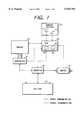
- FIG. 1is a diagram showing a schematic structure of an engine control system for a series hybrid vehicle according to a first preferred embodiment of the present invention
- FIG. 2Ais a diagram for explaining control patterns for controlling an engine operation of the series hybrid vehicle using an ECU
- FIG. 2Bis a diagram for explaining control patterns for controlling an engine operation of a parallel hybrid vehicle using an ECU
- FIGS. 3A and 3Bare diagrams for explaining the operation of the ECU in more detail
- FIG. 4is a diagram for explaining the operation of the ECU in more detail
- FIGS. 5A, 5B and 5Care diagrams for explaining the operation of the ECU in more detail
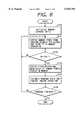
- FIG. 6is a flowchart for explaining the operation of the ECU
- FIG. 7Ais a diagram showing one example of output power of a battery while a vehicle is running according to the prior art
- FIG. 7Bis a diagram showing one example of output power of a battery while the vehicle is running according to the first preferred embodiment
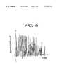
- FIG. 8is a diagram showing one example of power demand values derived per two seconds while the vehicle is running.
- FIG. 9is a diagram showing a schematic structure of an engine 10 control system for a parallel hybrid vehicle according to a second preferred embodiment of the present invention, wherein the power transmission system is also shown.
- FIG. 1is a diagram showing a schematic structure of an engine control system for a series hybrid vehicle according to a first preferred embodiment of the present invention.
- the engine control systemincludes an engine 40, a generator 30 coupled to the engine 40, an inverter 50 electrically connected to the generator 30, a battery 20 charged by the generator 30 via the inverter 50, and a motor 10 driven by the output power of the battery 20 and the output power of the generator 30 via the inverter 50.
- An ECU (electronic control unit) 60which controls an operation of the engine 40, is connected to a sensor section 70.
- the sensor section 70is provided with various sensors, such as an accelerator pedal sensor 71, a brake pedal sensor 72 and a speed sensor (not shown).
- the ECU 60includes memories for storing a later-described control program and various data, and interface circuits for sending and receiving signals relative to the associated components and the sensors of the engine control system.
- the engine 40is operated with WOT (wide open throttle) in case of the gasoline engine. Specifically, the engine 40 is operated with a throttle valve being fully open, and the output of the engine is controlled by the ECU 60 based on the fuel injection amount. Further, for the highly efficient operation, the output range of the engine is limited and the engine is of a type whose output is directly proportional to the speed thereof.
- WOTwide open throttle
- the generator 30is driven by the engine 40.
- the output power of the generator 30changes depending on the speed thereof, and the field current of the generator 30 is controlled by the ECU 60 via the inverter 50.
- the motor 10is in the form of a dc or ac motor whose output shaft is drivingly connected to driven wheels (not shown) of the vehicle via a power transmission mechanism (not shown).
- the inverter 50Under the control of the ECU 60, the inverter 50 normally connects the motor 10 to the battery 20 electrically during the vehicle running so that the motor 10 receives the power from the battery 20 to drive the vehicle. On the other hand, during the vehicle deceleration, the inverter 50 causes the motor 10 to work as a generator so that the battery 20 is charged by the generated deceleration regenerative power.
- the motor 10is driven by the output power of the generator 30 and the output power of the battery 20, and the residual power of the generator 30 is used for charging the battery 20 via the inverter 50.
- the ECU 60includes engine control means 61.
- the engine control means 61includes vehicle running state detecting means 62 and engine operation control means 63.
- the vehicle running state detecting means 62estimates the vehicle running state based on a frequency distribution of the values of power demanded by the vehicle when the vehicle is running (i.e., power demand values) which are derived from various sensor signals obtained at the sensor section 70 and a mean value of the power demand values.
- the engine operation control means 63selects one of several control patterns prestored in the memory of the ECU 60 based on the vehicle running state estimated by the vehicle running state detecting means 62, so as to control the operation of the engine 40 and thus the output power of the generator 30.
- FIG. 2Ais a diagram for explaining the foregoing control patterns for controlling the engine operation of the series hybrid vehicle by the engine operation control means 63.
- CFCRCrepresents constant-fuel-consumption-rate curves derived based on a relationship between the engine speed and the engine torque.
- the control patternsinclude (1) a high power constant (HPC) pattern in the optimum emission/fuel consumption range (OEFCR); (2) an intermediate power constant (IPC) pattern in the optimum emission/fuel consumption range; (3) a low power constant (LPC) pattern in the optimum emission/fuel consumption range; (4) a power varying pattern on an engine operating line (EOL) where the fuel consumption rate relative to the power is the best in the optimum emission/fuel consumption range.
- HPChigh power constant
- IPCintermediate power constant
- LPClow power constant
- EOLengine operating line
- FIGS. 3A and 3Bare diagrams for explaining the operation of the engine control means 61 in more detail.
- the vehicle running state detecting means 62estimates that the vehicle is stopped or in a traffic jam.
- the engine operation control means 63stops the engine 40 or selects the low power constant pattern so as to set the low power constant operation of the engine 40.
- the vehicle running state detecting means 62estimates that the vehicle is running on a downward slope.
- the engine operation control means 63stops the engine 40 or selects the low power constant pattern so as to set the low power constant operation of the engine 40.
- FIG. 4is a diagram for explaining the operation of the engine control means 61 in more detail.
- the vehicle running state detecting means 62estimates that the vehicle is running on an upward slope or under a heavy load.
- the engine operation control means 63selects the high power constant pattern so as to set the high power constant operation of the engine 40.
- the engine operation control means 63selects the intermediate power constant pattern so as to set the intermediate power constant operation of the engine 40.
- FIGS. 5A to 5Bare diagrams for explaining the operation of the engine control means 61 in more detail.
- the vehicle running state detecting means 62estimates that the vehicle is running on a road having repetitive upward and downward slopes.
- the engine operation control means 63selects the power varying pattern so as to set the power varying operation, wherein the speed of the engine 40 is changed depending on the power demand value.
- the engine operation control means 63selects the intermediate power constant pattern to set the intermediate power constant operation of the engine within the normal SOC control range.
- the target output powers of the generator 30 in the respective high, intermediate and low power constant operationsare determined within the optimum emission/fuel consumption range based on preselected factors of the vehicle.
- FIG. 6is a flowchart of a control routine representing the operation of the engine control means 61 of the ECU 60.
- the routinestarts when an engine switch is set on. Then, at step S100, the engine control means 61 executes the initialization process so that an address M of the memory for storing the power demand value is set to "0".
- the engine control means 61reads various sensor signals sent from the sensor section 70, derives the power demand values and stores it in the memory address M.
- the memory address Mis represented by the remainder of the following equation:
- step S102the engine control means 61 determines whether the number of the stored data in the memory is 100 or not. If positive, the routine proceeds to step S103. On the other hand, if negative, the routine returns to step S101 for repeating execution of step S101 until the answer at step S102 becomes positive.
- step S103that is, after a lapse of 100 seconds, the engine control means 61 derives the frequency distribution of the power demand values stored in the memory and the mean value thereof.
- the engine control means 61estimates the vehicle running state based on the frequency distribution of the power demand values and the mean value of such power demand values derived at step S103 and selects the optimum control pattern from the foregoing prestored control patterns based on the estimated vehicle running state.
- the predetermined vehicle running statesare stored in the memory of the ECU 60 so as to be identified by the engine control means 61 based on a combination of the frequency distribution of the power demand values and the mean value of the power demand values, and the foregoing four control patterns are stored in the memory of the ECU 60 so as to be selectable by the engine control means 61 based on the identified vehicle running state.
- the engine control means 61further controls the operation of the engine 40 according to the selected control pattern and thus the output power of the generator 30.
- step S105the engine control means 61 determines whether the vehicle running is finished. If positive, the routine terminates. On the other hand, if negative, the routine returns to step S101 so as to repeat execution of the foregoing processes.
- FIG. 7Ais a diagram showing one example of the output power of the battery according to the prior art
- FIG. 7Bis a diagram showing one example of the output power of the battery 20 according to the first preferred embodiment
- FIG. 8is a diagram showing one example of the power demand values derived per two seconds while the vehicle is running on a road having repetitive upward and downward slopes so that the power demand values largely and frequently fluctuate between the plus and minus regions.
- the output power of the battery shown in FIG. 7Ais caused when the vehicle runs on a road having repetitive upward and downward slopes with the power demand values shown in FIG. 8, while the power constant control of the engine is performed based on the mean value of the power demand values.
- the output power of the battery 20 shown in FIG. 7Bis caused when the vehicle runs on a road having repetitive upward and downward slopes with the power demand values shown in FIG. 8, while the foregoing power varying control of the engine is performed according to the first preferred embodiment.
- the generator output poweris controlled depending on the mean value of the power demand values, the output power of the battery caused by charging and discharging fluctuates over a wide range. Thus, an excessive burden is applied to the battery so as to shorten the life of the battery.
- FIG. 7Bif the speed of the engine 40 is changed, within the optimum emission/fuel consumption range, depending on the power demand values so as to control the output power of the generator 30 between Wmin and Wmax, the variation width of the output power of the battery 20 is smaller as compared with FIG. 7A so as to prolong the life of the battery.
- the speed of the engine 40is changed within the optimum emission/fuel consumption range depending on the power demand values so as to control the output power of the generator 30 when the power demand variation is large, for example, as shown in FIG. 8. This reduces the variation of the output power of the battery 20 so as to prolong the life of the battery 20.
- the engine 40is driven at a constant speed, which depends on the control pattern selected based on the frequency distribution of the power demand values and the mean value of the power demand values, so as to control the output power of the generator 30 to be constant. This improves the exhaust emission which would be otherwise deteriorated due to the change in operating state of the engine 40.
- FIG. 9is a diagram showing a schematic structure of an engine control system for a parallel hybrid vehicle according to a second preferred embodiment of the present invention, wherein the power transmission system is also shown.
- an engine 40 of the parallel hybrid vehicleoperats as a main driving source and is coupled to a rotor shaft of a motor/generator (MG) 80.
- the motor/generator (MG) 80operates as an auxiliary driving source.
- the rotor shaftis mechanically connected to a power transmission 90. Driven wheels of the vehicle are driven by the rotation power of the engine 40 or the MG 80 via the power transmission 90.
- the MG 80is connected to a 100 V high-voltage battery 20 via an inverter 50.
- the MG 80operates as a motor and a generator and thus produces the output torque as the motor or the regenerative braking torque as the generator depending on the exciting current value controlled by an ECU 60 via the inverter 50.
- the ECU 60electrically connects the MG 80 to the battery 20, and causes the MG 80 to work as the generator or the motor depending on a relationship between the values of power demanded by the vehicle when the vehicle is running (i.e., power demand values) derived from various detection signals of an acceleration pedal sensor 71, a brake pedal sensor 72 and a speed sensor and the like sent from a sensor section 70 and the output of the engine 40.
- the MG 80is caused to work as the generator so as to charge the battery 20 using the residual power.
- the MG 80is caused to work as the motor so as to make up for a shortage by drawing power from the battery 20.
- the ECU 60causes the MG 80 to work as the generator via the inverter 50 so as to charge the battery 20 using the generated deceleration regenerative power, and outputs a signal for stopping the fuel supply to the engine 40.
- the ECU 60includes engine control means 61.
- the engine control means 61includes vehicle running state detecting means 62 and engine operation control means 63.
- the vehicle running state detecting means 62estimates the vehicle running state based on a frequency distribution of the power demand values derived from various sensor signals obtained at the sensor section 70 and a mean value of the power demand values.
- the engine operation control means 63selects one of several control patterns prestored in the memory of the ECU 60 based on the vehicle running state estimated by the vehicle running state detecting means 62, so as to control operation of the engine 40.
- FIG. 2Bis a diagram for explaining the foregoing control patterns for controlling the engine operation of the parallel hybrid vehicle using the engine operation control means 63.
- CFCRCrepresents constant-fuel-consumption-rate curves derived based on a relationship between the engine speed and the engine torque.
- the control patternsinclude (1) a high power line (HPL) operation pattern in the optimum emission/fuel consumption range (OEFCR); (2) an intermediate power line (IPL) operation pattern (where the fuel consumption rate relative to the output power is the best) in the optimum emission/fuel consumption range; (3) a low power line (LPL) operation pattern in the optimum emission/fuel consumption range; (4) a power varying pattern within the optimum emission/fuel consumption range.
- HPLhigh power line
- IPLintermediate power line
- LPLlow power line
- Each of these four control patternsis stored in the memory of the ECU 60 so as to be selectable by the vehicle running state estimated by the vehicle running state detecting means 62.
- An operating point of the engine 40 on each of the high, intermediate and low power linesis determined based on a selected speed gear ratio or the like.
- the vehicle running state detecting means 62estimates that the vehicle is stopped or in a traffic jam.
- the engine operation control means 63sets the engine operation based on the low power line operation pattern.
- the vehicle running state detecting means 62estimates that the vehicle is running on a downward slope.
- the engine operation control means 63sets the engine operation based on the low power line operation pattern.
- the vehicle running state detecting means 62estimates that the vehicle is running on an upward slope or under a heavy load.
- the engine operation control means 63sets the engine operation based on the high power line operation pattern.
- the engine operation control means 63sets the engine operation based on the intermediate power line operation pattern.
- the vehicle running state detecting means 62estimates that the vehicle is running on a road having repetitive upward and downward slopes.
- the engine operation control means 63sets the engine operation based on the power varying pattern, wherein the output of the engine 40 is changed depending on the power demand values.
- the engine operation control means 63selects one of the high, intermediate and low power line operation patterns depending on the battery residual amount.
- the output of the engine 40is changed within the optimum emission/fuel consumption range depending on the power demand values so as to absorb variation of the power demand when the power demand variation is large. This reduces the variation of the output power of the battery 20 so as to prolong the life of the battery 20. Further, the energy loss due to charging can be reduced.
- the engine 40is driven along one of the preset lines depending on the frequency distribution of the power demand values and the mean value thereof. This improves the exhaust emission which would be otherwise deteriorated due to the torque fluctuation of the engine 40, and the energy loss due to charging can be reduced.
- the transmission 90By using a non-stage transmission, such as a CVT, as the transmission 90 to control the variation in engine speed, the deterioration of the exhaust emission can be further suppressed.
- a non-stage transmissionsuch as a CVT
Landscapes
- Engineering & Computer Science (AREA)
- Transportation (AREA)
- Mechanical Engineering (AREA)
- Chemical & Material Sciences (AREA)
- Combustion & Propulsion (AREA)
- Power Engineering (AREA)
- Life Sciences & Earth Sciences (AREA)
- Sustainable Development (AREA)
- Sustainable Energy (AREA)
- Electric Propulsion And Braking For Vehicles (AREA)
- Hybrid Electric Vehicles (AREA)
- Control Of Vehicle Engines Or Engines For Specific Uses (AREA)
- Control Of Eletrric Generators (AREA)
Abstract
Description
M=(M+1)/100
Claims (17)
Applications Claiming Priority (4)
| Application Number | Priority Date | Filing Date | Title |
|---|---|---|---|
| JP18905495 | 1995-07-25 | ||
| JP7-189054 | 1995-07-25 | ||
| JP8-008542 | 1996-01-22 | ||
| JP854296AJPH0998515A (en) | 1995-07-25 | 1996-01-22 | Hybrid vehicle engine control system |
Publications (1)
| Publication Number | Publication Date |
|---|---|
| US5939794Atrue US5939794A (en) | 1999-08-17 |
Family
ID=26343082
Family Applications (1)
| Application Number | Title | Priority Date | Filing Date |
|---|---|---|---|
| US08/686,389Expired - Fee RelatedUS5939794A (en) | 1995-07-25 | 1996-07-25 | Engine control system for hybrid vehicle |
Country Status (2)
| Country | Link |
|---|---|
| US (1) | US5939794A (en) |
| JP (1) | JPH0998515A (en) |
Cited By (82)
| Publication number | Priority date | Publication date | Assignee | Title |
|---|---|---|---|---|
| US6127813A (en)* | 1998-03-31 | 2000-10-03 | Honda Giken Kogyo Kabushiki Kaisha | Control system for hybrid vehicle |
| US6201312B1 (en)* | 1998-02-17 | 2001-03-13 | Toyota Jidosha Kabushiki Kaisha | Drive control system for hybrid vehicles |
| US6242873B1 (en)* | 2000-01-31 | 2001-06-05 | Azure Dynamics Inc. | Method and apparatus for adaptive hybrid vehicle control |
| US6274943B1 (en)* | 1998-12-18 | 2001-08-14 | Honda Giken Kogyo Kabushiki Kaisha | Engine-starting discrimination system for hybrid vehicle |
| US6326702B1 (en)* | 1998-12-18 | 2001-12-04 | Honda Giken Kogyo Kabushiki Kaisha | Output control system for series hybrid vehicle |
| EP1199205A3 (en)* | 2000-09-22 | 2002-01-02 | Nissan Motor Co., Ltd. | Control system for hybrid vehicle |
| US6487096B1 (en) | 1997-09-08 | 2002-11-26 | Capstone Turbine Corporation | Power controller |
| US6484830B1 (en) | 2000-04-26 | 2002-11-26 | Bowling Green State University | Hybrid electric vehicle |
| US20020175522A1 (en)* | 2001-01-30 | 2002-11-28 | Joel Wacknov | Distributed power system |
| WO2002096696A1 (en)* | 2001-04-06 | 2002-12-05 | Honeywell International Inc. | System and method for actively limiting the power drawn from a power distribution bus |
| US20020198648A1 (en)* | 1998-01-05 | 2002-12-26 | Mark Gilbreth | Method and system for control of turbogenerator power and temperature |
| US20030006076A1 (en)* | 2000-10-11 | 2003-01-09 | Tamor Michael Alan | Control system for a hybrid electric vehicle to anticipate the need for a mode change |
| US20030015873A1 (en)* | 2001-01-10 | 2003-01-23 | Claude Khalizadeh | Transient ride-through or load leveling power distribution system |
| US6564126B1 (en)* | 2000-05-10 | 2003-05-13 | Delphi Technologies, Inc. | System for automatically resetting an oil condition alarm light after an oil change |
| US20030158638A1 (en)* | 1999-07-30 | 2003-08-21 | Oshkosh Truck Corporation | Control system and method for electric vehicle |
| US6612112B2 (en) | 1998-12-08 | 2003-09-02 | Capstone Turbine Corporation | Transient turbine exhaust temperature control for a turbogenerator |
| US6615940B2 (en)* | 2000-01-19 | 2003-09-09 | Toyota Jidosha Kabushiki Kaisha | Control system for vehicle having fuel cell |
| US6629027B2 (en)* | 2001-10-11 | 2003-09-30 | Nissan Motor Co., Ltd. | Control device and control method for hybrid vehicle |
| US20030205422A1 (en)* | 2002-05-02 | 2003-11-06 | Oshkosh Truck Corporation | Hybrid vehicle with combustion engine/electric motor drive |
| US20040029678A1 (en)* | 2001-04-26 | 2004-02-12 | Atsushi Kayukawa | Controller of hybrid vehicle |
| US6735502B2 (en)* | 2001-10-01 | 2004-05-11 | Ford Global Technologies, Llc | Control system and method for a parallel hybrid electric vehicle |
| EP1218213A4 (en)* | 1999-10-05 | 2004-06-16 | Auto Viacao Abc Ltda | System for a hybrid vehicle; hybrid vehicle operated by the system and device for power supply and accumulation for the hybrid vehicle |
| US6757597B2 (en)* | 2001-01-31 | 2004-06-29 | Oshkosh Truck | A/C bus assembly for electronic traction vehicle |
| US20040135436A1 (en)* | 1998-04-02 | 2004-07-15 | Gilbreth Mark G | Power controller system and method |
| US20040142216A1 (en)* | 2001-12-19 | 2004-07-22 | Keisuke Wakabayashi | Vehicle fuel cell power plant warm-up control |
| US6784565B2 (en) | 1997-09-08 | 2004-08-31 | Capstone Turbine Corporation | Turbogenerator with electrical brake |
| US20040174018A1 (en)* | 2003-03-06 | 2004-09-09 | Yasumitsu Itoh | Power generation controller for AC generator |
| US20050119806A1 (en)* | 2001-01-31 | 2005-06-02 | Oshkosh Truck Corporation | System and method for braking in an electric vehicle |
| US20050145425A1 (en)* | 2003-09-25 | 2005-07-07 | Govt. Of The U.S.A. As Represented By The Admi. Of The U.S. Environmental Protection Agency | Methods of operating a series hybrid vehicle |
| US6960840B2 (en) | 1998-04-02 | 2005-11-01 | Capstone Turbine Corporation | Integrated turbine power generation system with catalytic reactor |
| US20050275081A1 (en)* | 2004-06-12 | 2005-12-15 | Roger Chang | Embedded chip semiconductor having dual electronic connection faces |
| US20050288148A1 (en)* | 2004-06-28 | 2005-12-29 | Caterpillar Inc. | Continuously variable transmission system with power boost |
| US7004273B1 (en) | 2000-04-26 | 2006-02-28 | Robert Gruenwald | Hybrid electric vehicle |
| US20060071645A1 (en)* | 2004-09-27 | 2006-04-06 | Oshkosh Truck Corporation | Status indicator for an energy storage device for use with an electric vehicle |
| US20060208568A1 (en)* | 2005-03-18 | 2006-09-21 | Toyota Jidosha Kabushiki Kaisha | Highly reliable vehicle system start controller |
| US7252165B1 (en) | 2000-04-26 | 2007-08-07 | Bowling Green State University | Hybrid electric vehicle |
| US7254468B2 (en) | 2001-12-21 | 2007-08-07 | Oshkosh Truck Corporation | Multi-network control system for a vehicle |
| US20070251740A1 (en)* | 2004-06-15 | 2007-11-01 | Caterpillar Inc. | Method for controlling an electric drive machine |
| US20070262586A1 (en)* | 2006-05-09 | 2007-11-15 | Nicolas Bouchon | Process and apparatus for reducing nitrogen oxide emissions in genset systems |
| US20070266711A1 (en)* | 2004-09-15 | 2007-11-22 | Robert Bosch Gmbh | Method for Operating a Vehicle Drive and Device for Carrying Out Said Method |
| US7302320B2 (en) | 2001-12-21 | 2007-11-27 | Oshkosh Truck Corporation | Failure mode operation for an electric vehicle |
| US20080059013A1 (en)* | 2006-09-01 | 2008-03-06 | Wei Liu | Method, apparatus, signals, and medium for managing power in a hybrid vehicle |
| US20080122228A1 (en)* | 2006-06-26 | 2008-05-29 | Wei Liu | Method, apparatus, signals and media, for selecting operating conditions of a genset |
| US20080293538A1 (en)* | 2007-05-02 | 2008-11-27 | Nissan Motor Co., Ltd. | Hybrid vehicle drive control apparatus and method |
| US20090030568A1 (en)* | 2006-02-21 | 2009-01-29 | Toyota Jidosha Kabushiki Kaisha | Hybrid Vehicle Controller |
| US20090076697A1 (en)* | 2007-09-14 | 2009-03-19 | Ford Global Technologies, Llc | Method and system for controlling a motive power system of an automotive vehicle |
| US20090090572A1 (en)* | 2005-12-20 | 2009-04-09 | Thomas Huber | Method for operating a hybrid vehicle |
| USRE40713E1 (en) | 1997-09-08 | 2009-05-19 | Capstone Turbine Corporation | Turbogenerator/motor controller |
| US20090173555A1 (en)* | 2006-05-30 | 2009-07-09 | Toyota Jidosha Kabushiki Kaisha | Motive Power Output Apparatus and Vehicle With the Same |
| US7605493B1 (en)* | 2005-11-09 | 2009-10-20 | Joseph P. Boudreaux | Electrically powered vehicle engine |
| US7711460B2 (en) | 2001-01-31 | 2010-05-04 | Oshkosh Corporation | Control system and method for electric vehicle |
| US20100109856A1 (en)* | 2008-10-30 | 2010-05-06 | Bayerische Motoren Werke Aktiengesellschaft | Information System |
| US20100235024A1 (en)* | 2006-02-10 | 2010-09-16 | Toyota Jidosha Kabushiki Kaisha | Hybrid vehicle battery life evaluating apparatus |
| US7835838B2 (en) | 1999-07-30 | 2010-11-16 | Oshkosh Corporation | Concrete placement vehicle control system and method |
| US20100305794A1 (en)* | 2006-12-22 | 2010-12-02 | Nederlandse Organisatie Voor Toegepastnatuurwetens | Vehicle system, and method |
| US20100304923A1 (en)* | 2006-10-23 | 2010-12-02 | Robert Bosch Gmbh | Method For Controlling A Hybrid Drive |
| US20110100731A1 (en)* | 2009-10-30 | 2011-05-05 | Hassan M Hassan | Perpetual fuel-free electric vehicle |
| US20110174561A1 (en)* | 2010-01-21 | 2011-07-21 | ePower Engine Systems, L.L.C. | Hydrocarbon Fueled-Electric Series Hybrid Propulsion Systems |
| US8139109B2 (en) | 2006-06-19 | 2012-03-20 | Oshkosh Corporation | Vision system for an autonomous vehicle |
| US8337352B2 (en) | 2010-06-22 | 2012-12-25 | Oshkosh Corporation | Electromechanical variable transmission |
| US20130096752A1 (en)* | 1998-09-14 | 2013-04-18 | Paice Llc | Hybrid vehicles |
| CN103144629A (en)* | 2013-03-26 | 2013-06-12 | 潍柴动力股份有限公司 | Power control system and power control method for hybrid vehicle |
| US20140021920A1 (en)* | 2011-04-08 | 2014-01-23 | Mitsubishi Electric Corporation | Power supply system for vehicle |
| US8761978B2 (en)* | 2011-03-23 | 2014-06-24 | General Electric Company | System for supplying propulsion energy from an auxiliary drive and method of making same |
| WO2014123472A1 (en)* | 2013-02-08 | 2014-08-14 | BAE Systems Hägglunds Aktiebolag | Method and system for controlling a driveline of a hybrid vehicle |
| US8947531B2 (en) | 2006-06-19 | 2015-02-03 | Oshkosh Corporation | Vehicle diagnostics based on information communicated between vehicles |
| US9114804B1 (en) | 2013-03-14 | 2015-08-25 | Oshkosh Defense, Llc | Vehicle drive and method with electromechanical variable transmission |
| CN105128855A (en)* | 2015-09-21 | 2015-12-09 | 大连理工大学 | A control method for a dual-axle parallel hybrid electric city bus |
| US9580067B2 (en) | 2013-11-29 | 2017-02-28 | Sanyo Electric Co., Ltd. | Charging/discharging control system for electricity storage device |
| US9650032B2 (en) | 2015-02-17 | 2017-05-16 | Oshkosh Corporation | Multi-mode electromechanical variable transmission |
| US9651120B2 (en) | 2015-02-17 | 2017-05-16 | Oshkosh Corporation | Multi-mode electromechanical variable transmission |
| US9656659B2 (en) | 2015-02-17 | 2017-05-23 | Oshkosh Corporation | Multi-mode electromechanical variable transmission |
| WO2018158571A1 (en)* | 2017-02-28 | 2018-09-07 | Tevva Motors Limited | Range extender |
| US10272897B2 (en)* | 2016-04-15 | 2019-04-30 | Hyundai Motor Company | Control method of power train for hybrid vehicle and control system for the same |
| US10421350B2 (en) | 2015-10-20 | 2019-09-24 | Oshkosh Corporation | Inline electromechanical variable transmission system |
| US10578195B2 (en) | 2015-02-17 | 2020-03-03 | Oshkosh Corporation | Inline electromechanical variable transmission system |
| US10584775B2 (en) | 2015-02-17 | 2020-03-10 | Oshkosh Corporation | Inline electromechanical variable transmission system |
| CN112373318A (en)* | 2020-10-22 | 2021-02-19 | 智新控制系统有限公司 | Range-extending vehicle control method and system |
| US10982736B2 (en) | 2015-02-17 | 2021-04-20 | Oshkosh Corporation | Multi-mode electromechanical variable transmission |
| US11035305B2 (en)* | 2019-04-11 | 2021-06-15 | Hyundai Motor Company | 2-cycle engine with valve system and method for controlling the engine |
| US11701959B2 (en) | 2015-02-17 | 2023-07-18 | Oshkosh Corporation | Inline electromechanical variable transmission system |
| US12078231B2 (en) | 2015-02-17 | 2024-09-03 | Oshkosh Corporation | Inline electromechanical variable transmission system |
Families Citing this family (6)
| Publication number | Priority date | Publication date | Assignee | Title |
|---|---|---|---|---|
| JP4158615B2 (en)* | 2003-06-20 | 2008-10-01 | 株式会社デンソー | Vehicle power supply |
| JP4816128B2 (en)* | 2006-02-21 | 2011-11-16 | 株式会社デンソー | Vehicle power generation control device |
| JP4986932B2 (en)* | 2007-05-28 | 2012-07-25 | 本田技研工業株式会社 | Power supply system |
| CN102460949B (en)* | 2009-06-16 | 2015-01-21 | 住友重机械工程服务株式会社 | Hybrid electric power source device for crane and method for controlling hybrid electric power source device for crane |
| DE102013014457A1 (en)* | 2013-08-30 | 2015-03-05 | Fraunhofer-Gesellschaft zur Förderung der angewandten Forschung e.V. | Method for driving a motor vehicle and drive system for a motor vehicle |
| KR102558740B1 (en) | 2016-10-27 | 2023-07-24 | 삼성전자주식회사 | Method, apparatus, and system for managing battery |
Citations (13)
| Publication number | Priority date | Publication date | Assignee | Title |
|---|---|---|---|---|
| US5176213A (en)* | 1987-12-09 | 1993-01-05 | Aisin Aw Co., Ltd. | Driving force distribution system for hybrid vehicles |
| JPH06245320A (en)* | 1993-02-18 | 1994-09-02 | Toyota Motor Corp | Controller for engine driven generator in electric automobile |
| US5418437A (en)* | 1992-11-16 | 1995-05-23 | Hydro-Quebec | Motor vehicle drive system for a motor vehicle having an electric motor system, and a method of operating said drive system |
| US5428274A (en)* | 1991-11-22 | 1995-06-27 | Toyota Jidosha Kabushiki Kaisha | Drive control apparatus of series hybrid vehicle |
| US5495906A (en)* | 1993-01-25 | 1996-03-05 | Toyota Jidosha Kabushiki Kaisha | Controller of hybrid electric vehicle |
| US5545928A (en)* | 1993-09-17 | 1996-08-13 | Toyota Jidosha Kabushiki Kaisha | Electric power generation control method in a hybrid vehicle utilizing detected generator output and engine revolutions |
| US5550445A (en)* | 1993-09-24 | 1996-08-27 | Toyota Jidosha Kabushiki Kaisha | Generator controller and controlling method for hybrid vehicle |
| US5586613A (en)* | 1993-04-22 | 1996-12-24 | The Texas A&M University System | Electrically peaking hybrid system and method |
| US5608310A (en)* | 1994-04-20 | 1997-03-04 | Mitsubishi Denki Kabushiki Kaisha | AC generator control apparatus for a motor vehicle |
| US5625921A (en)* | 1996-04-04 | 1997-05-06 | Prince Corporation | Combined assist handle and hanger support |
| US5635805A (en)* | 1994-06-29 | 1997-06-03 | Toyota Jidosha Kabushiki Kaisha | Hybrid vehicle |
| US5650931A (en)* | 1994-02-21 | 1997-07-22 | Toyota Jidosha Kabushiki Kaisha | Generator output controller for electric vehicle with mounted generator |
| US5650713A (en)* | 1994-07-01 | 1997-07-22 | Nippondenso Co., Ltd. | Control device for a hybrid automobile |
- 1996
- 1996-01-22JPJP854296Apatent/JPH0998515A/enactivePending
- 1996-07-25USUS08/686,389patent/US5939794A/ennot_activeExpired - Fee Related
Patent Citations (13)
| Publication number | Priority date | Publication date | Assignee | Title |
|---|---|---|---|---|
| US5176213A (en)* | 1987-12-09 | 1993-01-05 | Aisin Aw Co., Ltd. | Driving force distribution system for hybrid vehicles |
| US5428274A (en)* | 1991-11-22 | 1995-06-27 | Toyota Jidosha Kabushiki Kaisha | Drive control apparatus of series hybrid vehicle |
| US5418437A (en)* | 1992-11-16 | 1995-05-23 | Hydro-Quebec | Motor vehicle drive system for a motor vehicle having an electric motor system, and a method of operating said drive system |
| US5495906A (en)* | 1993-01-25 | 1996-03-05 | Toyota Jidosha Kabushiki Kaisha | Controller of hybrid electric vehicle |
| JPH06245320A (en)* | 1993-02-18 | 1994-09-02 | Toyota Motor Corp | Controller for engine driven generator in electric automobile |
| US5586613A (en)* | 1993-04-22 | 1996-12-24 | The Texas A&M University System | Electrically peaking hybrid system and method |
| US5545928A (en)* | 1993-09-17 | 1996-08-13 | Toyota Jidosha Kabushiki Kaisha | Electric power generation control method in a hybrid vehicle utilizing detected generator output and engine revolutions |
| US5550445A (en)* | 1993-09-24 | 1996-08-27 | Toyota Jidosha Kabushiki Kaisha | Generator controller and controlling method for hybrid vehicle |
| US5650931A (en)* | 1994-02-21 | 1997-07-22 | Toyota Jidosha Kabushiki Kaisha | Generator output controller for electric vehicle with mounted generator |
| US5608310A (en)* | 1994-04-20 | 1997-03-04 | Mitsubishi Denki Kabushiki Kaisha | AC generator control apparatus for a motor vehicle |
| US5635805A (en)* | 1994-06-29 | 1997-06-03 | Toyota Jidosha Kabushiki Kaisha | Hybrid vehicle |
| US5650713A (en)* | 1994-07-01 | 1997-07-22 | Nippondenso Co., Ltd. | Control device for a hybrid automobile |
| US5625921A (en)* | 1996-04-04 | 1997-05-06 | Prince Corporation | Combined assist handle and hanger support |
Cited By (163)
| Publication number | Priority date | Publication date | Assignee | Title |
|---|---|---|---|---|
| US6487096B1 (en) | 1997-09-08 | 2002-11-26 | Capstone Turbine Corporation | Power controller |
| USRE40713E1 (en) | 1997-09-08 | 2009-05-19 | Capstone Turbine Corporation | Turbogenerator/motor controller |
| US6784565B2 (en) | 1997-09-08 | 2004-08-31 | Capstone Turbine Corporation | Turbogenerator with electrical brake |
| US20020198648A1 (en)* | 1998-01-05 | 2002-12-26 | Mark Gilbreth | Method and system for control of turbogenerator power and temperature |
| US6870279B2 (en) | 1998-01-05 | 2005-03-22 | Capstone Turbine Corporation | Method and system for control of turbogenerator power and temperature |
| US6201312B1 (en)* | 1998-02-17 | 2001-03-13 | Toyota Jidosha Kabushiki Kaisha | Drive control system for hybrid vehicles |
| US6127813A (en)* | 1998-03-31 | 2000-10-03 | Honda Giken Kogyo Kabushiki Kaisha | Control system for hybrid vehicle |
| US6960840B2 (en) | 1998-04-02 | 2005-11-01 | Capstone Turbine Corporation | Integrated turbine power generation system with catalytic reactor |
| US20040135436A1 (en)* | 1998-04-02 | 2004-07-15 | Gilbreth Mark G | Power controller system and method |
| US8630761B2 (en)* | 1998-09-14 | 2014-01-14 | Paice Llc | Hybrid vehicles |
| US20130096752A1 (en)* | 1998-09-14 | 2013-04-18 | Paice Llc | Hybrid vehicles |
| US6612112B2 (en) | 1998-12-08 | 2003-09-02 | Capstone Turbine Corporation | Transient turbine exhaust temperature control for a turbogenerator |
| US6326702B1 (en)* | 1998-12-18 | 2001-12-04 | Honda Giken Kogyo Kabushiki Kaisha | Output control system for series hybrid vehicle |
| US6274943B1 (en)* | 1998-12-18 | 2001-08-14 | Honda Giken Kogyo Kabushiki Kaisha | Engine-starting discrimination system for hybrid vehicle |
| US6885920B2 (en) | 1999-07-30 | 2005-04-26 | Oshkosh Truck Corporation | Control system and method for electric vehicle |
| US7835838B2 (en) | 1999-07-30 | 2010-11-16 | Oshkosh Corporation | Concrete placement vehicle control system and method |
| US20030158638A1 (en)* | 1999-07-30 | 2003-08-21 | Oshkosh Truck Corporation | Control system and method for electric vehicle |
| EP1218213A4 (en)* | 1999-10-05 | 2004-06-16 | Auto Viacao Abc Ltda | System for a hybrid vehicle; hybrid vehicle operated by the system and device for power supply and accumulation for the hybrid vehicle |
| US6615940B2 (en)* | 2000-01-19 | 2003-09-09 | Toyota Jidosha Kabushiki Kaisha | Control system for vehicle having fuel cell |
| WO2001054940A1 (en)* | 2000-01-31 | 2001-08-02 | Azure Dynamics Inc. | Method and apparatus for adaptive hybrid vehicle control |
| US6242873B1 (en)* | 2000-01-31 | 2001-06-05 | Azure Dynamics Inc. | Method and apparatus for adaptive hybrid vehicle control |
| US7252165B1 (en) | 2000-04-26 | 2007-08-07 | Bowling Green State University | Hybrid electric vehicle |
| US6484830B1 (en) | 2000-04-26 | 2002-11-26 | Bowling Green State University | Hybrid electric vehicle |
| US6651759B1 (en) | 2000-04-26 | 2003-11-25 | Bowling Green State University | Hybrid electric vehicle |
| US7004273B1 (en) | 2000-04-26 | 2006-02-28 | Robert Gruenwald | Hybrid electric vehicle |
| US6564126B1 (en)* | 2000-05-10 | 2003-05-13 | Delphi Technologies, Inc. | System for automatically resetting an oil condition alarm light after an oil change |
| EP1199205A3 (en)* | 2000-09-22 | 2002-01-02 | Nissan Motor Co., Ltd. | Control system for hybrid vehicle |
| US7753150B2 (en) | 2000-10-11 | 2010-07-13 | Ford Global Technologies, Llc | Control system for a hybrid electric vehicle to anticipate the need for a mode change |
| US20030006076A1 (en)* | 2000-10-11 | 2003-01-09 | Tamor Michael Alan | Control system for a hybrid electric vehicle to anticipate the need for a mode change |
| US7021409B2 (en) | 2000-10-11 | 2006-04-04 | Ford Global Technologies, Llc | Control system for a hybrid electric vehicle to anticipate the need for a mode change |
| US20080224478A1 (en)* | 2000-10-11 | 2008-09-18 | Ford Global Technologies, Llc | Control System for a Hybrid Electric Vehicle to Anticipate the Need for a Mode Change |
| US6787933B2 (en) | 2001-01-10 | 2004-09-07 | Capstone Turbine Corporation | Power generation system having transient ride-through/load-leveling capabilities |
| US20030015873A1 (en)* | 2001-01-10 | 2003-01-23 | Claude Khalizadeh | Transient ride-through or load leveling power distribution system |
| US20020175522A1 (en)* | 2001-01-30 | 2002-11-28 | Joel Wacknov | Distributed power system |
| US20050119806A1 (en)* | 2001-01-31 | 2005-06-02 | Oshkosh Truck Corporation | System and method for braking in an electric vehicle |
| US7164977B2 (en) | 2001-01-31 | 2007-01-16 | Oshkosh Truck Corporation | A/C bus assembly for electronic traction vehicle |
| US7711460B2 (en) | 2001-01-31 | 2010-05-04 | Oshkosh Corporation | Control system and method for electric vehicle |
| US7848857B2 (en) | 2001-01-31 | 2010-12-07 | Oshkosh Corporation | System and method for braking in an electric vehicle |
| US6757597B2 (en)* | 2001-01-31 | 2004-06-29 | Oshkosh Truck | A/C bus assembly for electronic traction vehicle |
| US7379797B2 (en) | 2001-01-31 | 2008-05-27 | Oshkosh Truck Corporation | System and method for braking in an electric vehicle |
| US6792338B2 (en) | 2001-04-06 | 2004-09-14 | Honeywell International, Inc. | System and method for actively limiting the power drawn from a power distribution bus |
| WO2002096696A1 (en)* | 2001-04-06 | 2002-12-05 | Honeywell International Inc. | System and method for actively limiting the power drawn from a power distribution bus |
| US6817964B2 (en)* | 2001-04-26 | 2004-11-16 | Aisin Aw Co., Ltd. | Control apparatus of hybrid vehicle |
| US20040029678A1 (en)* | 2001-04-26 | 2004-02-12 | Atsushi Kayukawa | Controller of hybrid vehicle |
| US6735502B2 (en)* | 2001-10-01 | 2004-05-11 | Ford Global Technologies, Llc | Control system and method for a parallel hybrid electric vehicle |
| US6629027B2 (en)* | 2001-10-11 | 2003-09-30 | Nissan Motor Co., Ltd. | Control device and control method for hybrid vehicle |
| US7112381B2 (en)* | 2001-12-19 | 2006-09-26 | Nissan Motor Co., Ltd. | Vehicle fuel cell power plant warm-up control |
| US20040142216A1 (en)* | 2001-12-19 | 2004-07-22 | Keisuke Wakabayashi | Vehicle fuel cell power plant warm-up control |
| US8000850B2 (en) | 2001-12-21 | 2011-08-16 | Oshkosh Truck Corporation | Failure mode operation for an electric vehicle |
| US7254468B2 (en) | 2001-12-21 | 2007-08-07 | Oshkosh Truck Corporation | Multi-network control system for a vehicle |
| US7302320B2 (en) | 2001-12-21 | 2007-11-27 | Oshkosh Truck Corporation | Failure mode operation for an electric vehicle |
| US7520354B2 (en) | 2002-05-02 | 2009-04-21 | Oshkosh Truck Corporation | Hybrid vehicle with combustion engine/electric motor drive |
| US20030205422A1 (en)* | 2002-05-02 | 2003-11-06 | Oshkosh Truck Corporation | Hybrid vehicle with combustion engine/electric motor drive |
| US20090194347A1 (en)* | 2002-05-02 | 2009-08-06 | Oshkosh Corporation | Hybrid vehicle with combustion engine/electric motor drive |
| US7023102B2 (en)* | 2003-03-06 | 2006-04-04 | Suzuki Motor Corporation | Power generation controller for AC generator |
| US20040174018A1 (en)* | 2003-03-06 | 2004-09-09 | Yasumitsu Itoh | Power generation controller for AC generator |
| US20050145425A1 (en)* | 2003-09-25 | 2005-07-07 | Govt. Of The U.S.A. As Represented By The Admi. Of The U.S. Environmental Protection Agency | Methods of operating a series hybrid vehicle |
| US7857082B2 (en) | 2003-09-25 | 2010-12-28 | The United States Of America, As Represented By The Administrator Of The U.S. Environmental Protection Agency | Methods of operating a series hybrid vehicle |
| US8381851B2 (en) | 2003-09-25 | 2013-02-26 | The United States Of America, As Represented By The Administrator Of The U.S. Environmental Protection Agency | Methods of operating a series hybrid vehicle |
| US20050145426A1 (en)* | 2003-09-25 | 2005-07-07 | GOV. of the U.S.A. as represented by the Administrator of the U.S. environmental protection | Methods of operating a series hybrid vehicle |
| US7456509B2 (en) | 2003-09-25 | 2008-11-25 | The United States Of America As Represented By The Administrator Of The U.S. Environmental Protection Agency | Methods of operating a series hybrid vehicle |
| US20050275081A1 (en)* | 2004-06-12 | 2005-12-15 | Roger Chang | Embedded chip semiconductor having dual electronic connection faces |
| US7350611B2 (en) | 2004-06-15 | 2008-04-01 | Caterpillar Inc | Method for controlling an electric drive machine |
| US20070251740A1 (en)* | 2004-06-15 | 2007-11-01 | Caterpillar Inc. | Method for controlling an electric drive machine |
| US7469761B2 (en) | 2004-06-28 | 2008-12-30 | Caterpillar Inc. | Continuously variable transmission system with power boost |
| WO2006006985A1 (en)* | 2004-06-28 | 2006-01-19 | Caterpillar Inc. | Continuously variable transmission system with power boost |
| US20050288148A1 (en)* | 2004-06-28 | 2005-12-29 | Caterpillar Inc. | Continuously variable transmission system with power boost |
| US20070266711A1 (en)* | 2004-09-15 | 2007-11-22 | Robert Bosch Gmbh | Method for Operating a Vehicle Drive and Device for Carrying Out Said Method |
| US20060071645A1 (en)* | 2004-09-27 | 2006-04-06 | Oshkosh Truck Corporation | Status indicator for an energy storage device for use with an electric vehicle |
| US7439711B2 (en) | 2004-09-27 | 2008-10-21 | Oshkosh Corporation | Energy storage device including a status indicator |
| US7689335B2 (en)* | 2005-03-18 | 2010-03-30 | Toyota Jidosha Kabushik Kaisha | Highly reliable vehicle system start controller |
| US20060208568A1 (en)* | 2005-03-18 | 2006-09-21 | Toyota Jidosha Kabushiki Kaisha | Highly reliable vehicle system start controller |
| US7605493B1 (en)* | 2005-11-09 | 2009-10-20 | Joseph P. Boudreaux | Electrically powered vehicle engine |
| US8037955B2 (en)* | 2005-12-20 | 2011-10-18 | Robert Bosh Gmbh | Method for operating a hybrid vehicle |
| US20090090572A1 (en)* | 2005-12-20 | 2009-04-09 | Thomas Huber | Method for operating a hybrid vehicle |
| US8676482B2 (en)* | 2006-02-10 | 2014-03-18 | Toyota Jidosha Kabushiki Kaisha | Hybrid vehicle battery life evaluating apparatus |
| US20100235024A1 (en)* | 2006-02-10 | 2010-09-16 | Toyota Jidosha Kabushiki Kaisha | Hybrid vehicle battery life evaluating apparatus |
| US20090030568A1 (en)* | 2006-02-21 | 2009-01-29 | Toyota Jidosha Kabushiki Kaisha | Hybrid Vehicle Controller |
| US8340849B2 (en)* | 2006-02-21 | 2012-12-25 | Toyota Jidosha Kabushiki Kaisha | Hybrid vehicle controller |
| US8515607B2 (en) | 2006-02-21 | 2013-08-20 | Toyota Jidosha Kabushiki Kaisha | Hybrid vehicle controller |
| US7728448B2 (en) | 2006-05-09 | 2010-06-01 | Azure Dynamics, Inc. | Process and apparatus for reducing nitrogen oxide emissions in genset systems |
| US20070262586A1 (en)* | 2006-05-09 | 2007-11-15 | Nicolas Bouchon | Process and apparatus for reducing nitrogen oxide emissions in genset systems |
| US8164282B2 (en)* | 2006-05-30 | 2012-04-24 | Toyota Jidosha Kabushiki Kaisha | Motive power output apparatus and vehicle with the same |
| US20090173555A1 (en)* | 2006-05-30 | 2009-07-09 | Toyota Jidosha Kabushiki Kaisha | Motive Power Output Apparatus and Vehicle With the Same |
| US9420203B2 (en) | 2006-06-19 | 2016-08-16 | Oshkosh Defense, Llc | Vision system for a vehicle |
| US8947531B2 (en) | 2006-06-19 | 2015-02-03 | Oshkosh Corporation | Vehicle diagnostics based on information communicated between vehicles |
| US8139109B2 (en) | 2006-06-19 | 2012-03-20 | Oshkosh Corporation | Vision system for an autonomous vehicle |
| US9403529B2 (en) | 2006-06-26 | 2016-08-02 | Ge Hybrid Technologies, Llc | Method, apparatus, signals and media, for selecting operating conditions of a genset |
| US8655570B2 (en) | 2006-06-26 | 2014-02-18 | Mosaid Technologies Incorporated | Method, apparatus, signals and media, for selecting operating conditions of a genset |
| EP2620342A3 (en)* | 2006-06-26 | 2016-08-10 | GE Hybrid Technologies, LLC | Method, apparatus, signals, and media, for selecting operating conditions of a genset |
| US20080122228A1 (en)* | 2006-06-26 | 2008-05-29 | Wei Liu | Method, apparatus, signals and media, for selecting operating conditions of a genset |
| US8346416B2 (en) | 2006-06-26 | 2013-01-01 | Azure Dynamics, Inc. | Method, apparatus, signals and media, for selecting operating conditions of a genset |
| US9020734B2 (en) | 2006-06-26 | 2015-04-28 | Ge Hybrid Technologies, Llc | Method, apparatus, signals and media, for selecting operating conditions of a genset |
| US7826939B2 (en) | 2006-09-01 | 2010-11-02 | Azure Dynamics, Inc. | Method, apparatus, signals, and medium for managing power in a hybrid vehicle |
| EP2062220A4 (en)* | 2006-09-01 | 2010-01-13 | Azure Dynamics Inc | Cost minimization for hybrid vehicle power management |
| US20080059013A1 (en)* | 2006-09-01 | 2008-03-06 | Wei Liu | Method, apparatus, signals, and medium for managing power in a hybrid vehicle |
| US8738203B2 (en) | 2006-09-01 | 2014-05-27 | Conversant Intellectual Property Management Inc. | Method, apparatus, signals, and medium for managing power in a hybrid vehicle |
| US9365132B2 (en) | 2006-09-01 | 2016-06-14 | Ge Hybrid Technologies, Llc | Method, apparatus, signals, and medium for managing power in a hybrid vehicle |
| US20110112711A1 (en)* | 2006-09-01 | 2011-05-12 | Wei Liu | Method, apparatus, signals, and medium for managing power in a hybrid vehicle |
| US8529399B2 (en)* | 2006-10-23 | 2013-09-10 | Robert Bosch Gmbh | Method for controlling a hybrid drive |
| US20100304923A1 (en)* | 2006-10-23 | 2010-12-02 | Robert Bosch Gmbh | Method For Controlling A Hybrid Drive |
| US20100305794A1 (en)* | 2006-12-22 | 2010-12-02 | Nederlandse Organisatie Voor Toegepastnatuurwetens | Vehicle system, and method |
| US8825242B2 (en)* | 2006-12-22 | 2014-09-02 | Nederlandse Organisatie Voor Toegepast-Natuurwetenschappelijk Onderzoek Tno | Vehicle system, and method |
| US8007401B2 (en) | 2007-05-02 | 2011-08-30 | Nissan Motor Co., Ltd. | Hybrid vehicle drive control apparatus and method |
| EP1987995A3 (en)* | 2007-05-02 | 2009-09-30 | Nissan Motor Co., Ltd. | Hybrid vehicle drive control apparatus and method |
| US20080293538A1 (en)* | 2007-05-02 | 2008-11-27 | Nissan Motor Co., Ltd. | Hybrid vehicle drive control apparatus and method |
| US7809487B2 (en) | 2007-09-14 | 2010-10-05 | Ford Global Technologies, Llc | Method and system for controlling a motive power system of an automotive vehicle |
| US20090076697A1 (en)* | 2007-09-14 | 2009-03-19 | Ford Global Technologies, Llc | Method and system for controlling a motive power system of an automotive vehicle |
| US20100109856A1 (en)* | 2008-10-30 | 2010-05-06 | Bayerische Motoren Werke Aktiengesellschaft | Information System |
| US8362892B2 (en)* | 2008-10-30 | 2013-01-29 | Bayerische Motoren Werke Aktiengesellschaft | Information system |
| US20110100731A1 (en)* | 2009-10-30 | 2011-05-05 | Hassan M Hassan | Perpetual fuel-free electric vehicle |
| US8783396B2 (en) | 2010-01-21 | 2014-07-22 | Epower Engine Systems, Llc | Hydrocarbon fueled-electric series hybrid propulsion systems |
| US20110174561A1 (en)* | 2010-01-21 | 2011-07-21 | ePower Engine Systems, L.L.C. | Hydrocarbon Fueled-Electric Series Hybrid Propulsion Systems |
| US10843549B2 (en) | 2010-06-22 | 2020-11-24 | Oshkosh Defense, Llc | Electromechanical variable transmission |
| US8864613B2 (en) | 2010-06-22 | 2014-10-21 | Oshkosh Corporation | Electromechanical variable transmission |
| US10029556B2 (en) | 2010-06-22 | 2018-07-24 | Oshkosh Defense, Llc | Electromechanical variable transmission |
| US9428042B2 (en) | 2010-06-22 | 2016-08-30 | Oshkosh Defense, Llc | Electromechanical variable transmission |
| US10457134B2 (en) | 2010-06-22 | 2019-10-29 | Oshkosh Defense, Llc | Electromechanical variable transmission |
| US8337352B2 (en) | 2010-06-22 | 2012-12-25 | Oshkosh Corporation | Electromechanical variable transmission |
| US8761978B2 (en)* | 2011-03-23 | 2014-06-24 | General Electric Company | System for supplying propulsion energy from an auxiliary drive and method of making same |
| US10343533B2 (en)* | 2011-04-08 | 2019-07-09 | Mitsubishi Electric Corporation | Power supply system with improved energy recovery from regenerative braking |
| US20140021920A1 (en)* | 2011-04-08 | 2014-01-23 | Mitsubishi Electric Corporation | Power supply system for vehicle |
| WO2014123472A1 (en)* | 2013-02-08 | 2014-08-14 | BAE Systems Hägglunds Aktiebolag | Method and system for controlling a driveline of a hybrid vehicle |
| US9132736B1 (en) | 2013-03-14 | 2015-09-15 | Oshkosh Defense, Llc | Methods, systems, and vehicles with electromechanical variable transmission |
| US9821789B2 (en) | 2013-03-14 | 2017-11-21 | Oshkosh Defense, Llc | Vehicle drive and method with electromechanical variable transmission |
| US9452750B2 (en) | 2013-03-14 | 2016-09-27 | Oshkosh Defense, Llc | Methods, systems, and vehicles with electromechanical variable transmission |
| US10315643B2 (en) | 2013-03-14 | 2019-06-11 | Oshkosh Defense, Llc | Methods, systems, and vehicles with electromechanical variable transmission |
| US11827207B2 (en) | 2013-03-14 | 2023-11-28 | Oshkosh Defense, Llc | Drive train for a vehicle |
| US10392000B2 (en) | 2013-03-14 | 2019-08-27 | Oshkosh Defense, Llc | Vehicle drive and method with electromechanical variable transmission |
| US11440527B2 (en) | 2013-03-14 | 2022-09-13 | Oshkosh Defense, Llc | Methods and systems for vehicle drive |
| US9376102B1 (en) | 2013-03-14 | 2016-06-28 | Oshkosh Defense, Llc | Vehicle drive and method with electromechanical variable transmission |
| US11299139B2 (en) | 2013-03-14 | 2022-04-12 | Oshkosh Defense, Llc | Drive train for a vehicle |
| US12214770B2 (en) | 2013-03-14 | 2025-02-04 | Oshkosh Defense, Llc | Drive train for a vehicle |
| US11052899B2 (en) | 2013-03-14 | 2021-07-06 | Oshkosh Defense, Llc | Vehicle drive and method with electromechanical variable transmission |
| US9114804B1 (en) | 2013-03-14 | 2015-08-25 | Oshkosh Defense, Llc | Vehicle drive and method with electromechanical variable transmission |
| CN103144629A (en)* | 2013-03-26 | 2013-06-12 | 潍柴动力股份有限公司 | Power control system and power control method for hybrid vehicle |
| CN103144629B (en)* | 2013-03-26 | 2016-04-06 | 潍柴动力股份有限公司 | A kind of power control system of motor vehicle driven by mixed power |
| US9580067B2 (en) | 2013-11-29 | 2017-02-28 | Sanyo Electric Co., Ltd. | Charging/discharging control system for electricity storage device |
| US9651120B2 (en) | 2015-02-17 | 2017-05-16 | Oshkosh Corporation | Multi-mode electromechanical variable transmission |
| US9656659B2 (en) | 2015-02-17 | 2017-05-23 | Oshkosh Corporation | Multi-mode electromechanical variable transmission |
| US12228195B2 (en) | 2015-02-17 | 2025-02-18 | Oshkosh Corporation | Driveline for electrified vehicle |
| US12078231B2 (en) | 2015-02-17 | 2024-09-03 | Oshkosh Corporation | Inline electromechanical variable transmission system |
| US10160438B2 (en) | 2015-02-17 | 2018-12-25 | Oshkosh Corporation | Multi-mode electromechanical variable transmission |
| US10578195B2 (en) | 2015-02-17 | 2020-03-03 | Oshkosh Corporation | Inline electromechanical variable transmission system |
| US10584775B2 (en) | 2015-02-17 | 2020-03-10 | Oshkosh Corporation | Inline electromechanical variable transmission system |
| US9650032B2 (en) | 2015-02-17 | 2017-05-16 | Oshkosh Corporation | Multi-mode electromechanical variable transmission |
| US11701959B2 (en) | 2015-02-17 | 2023-07-18 | Oshkosh Corporation | Inline electromechanical variable transmission system |
| US10935112B2 (en) | 2015-02-17 | 2021-03-02 | Oshkosh Corporation | Inline electromechanical variable transmission system |
| US10967728B2 (en) | 2015-02-17 | 2021-04-06 | Oshkosh Corporation | Multi-mode electromechanical variable transmission |
| US10974713B2 (en) | 2015-02-17 | 2021-04-13 | Oshkosh Corporation | Multi-mode electromechanical variable transmission |
| US10982736B2 (en) | 2015-02-17 | 2021-04-20 | Oshkosh Corporation | Multi-mode electromechanical variable transmission |
| US10989279B2 (en) | 2015-02-17 | 2021-04-27 | Oshkosh Corporation | Multi-mode electromechanical variable transmission |
| US9908520B2 (en) | 2015-02-17 | 2018-03-06 | Oshkosh Corporation | Multi-mode electromechanical variable transmission |
| US11009104B2 (en) | 2015-02-17 | 2021-05-18 | Oshkosh Corporation | Inline electromechanical variable transmission system |
| CN105128855A (en)* | 2015-09-21 | 2015-12-09 | 大连理工大学 | A control method for a dual-axle parallel hybrid electric city bus |
| US11007860B2 (en) | 2015-10-20 | 2021-05-18 | Oshkosh Corporation | Inline electromechanical variable transmission system |
| US10421350B2 (en) | 2015-10-20 | 2019-09-24 | Oshkosh Corporation | Inline electromechanical variable transmission system |
| US10272897B2 (en)* | 2016-04-15 | 2019-04-30 | Hyundai Motor Company | Control method of power train for hybrid vehicle and control system for the same |
| WO2018158571A1 (en)* | 2017-02-28 | 2018-09-07 | Tevva Motors Limited | Range extender |
| GB2562438B (en)* | 2017-02-28 | 2019-07-10 | Tevva Motors Ltd | Range Extender |
| GB2562438A (en)* | 2017-02-28 | 2018-11-14 | Tevva Motors Ltd | Range Extender |
| US11035305B2 (en)* | 2019-04-11 | 2021-06-15 | Hyundai Motor Company | 2-cycle engine with valve system and method for controlling the engine |
| CN112373318A (en)* | 2020-10-22 | 2021-02-19 | 智新控制系统有限公司 | Range-extending vehicle control method and system |
Also Published As
| Publication number | Publication date |
|---|---|
| JPH0998515A (en) | 1997-04-08 |
Similar Documents
| Publication | Publication Date | Title |
|---|---|---|
| US5939794A (en) | Engine control system for hybrid vehicle | |
| US5786640A (en) | Generator control system for a hybrid vehicle driven by an electric motor and an internal combustion engine | |
| US6891279B2 (en) | Vehicle control system and control method | |
| US7055636B2 (en) | Drive control device for hybrid vehicle | |
| US7015676B2 (en) | Battery control apparatus | |
| EP1129889B1 (en) | Regeneration control device of hybrid electric vehicle | |
| US5664635A (en) | Control system for inhibiting unintended use of hybrid electric vehicle | |
| JP3044880B2 (en) | Drive control device for series hybrid vehicles | |
| US7034482B2 (en) | Regeneration control for hybrid vehicle | |
| US7633247B2 (en) | Control apparatus for motor generator of hybrid vehicle | |
| JP3164821B2 (en) | Non-tracked vehicle with power / power converter and acceleration lever | |
| US6314346B1 (en) | Control system for hybrid vehicle | |
| EP1545924B1 (en) | Power control apparatus for hybrid vehicle | |
| KR20050057422A (en) | General drive control system and general drive control method | |
| EP0822114B1 (en) | Control system for hybrid vehicle | |
| US6362536B1 (en) | Apparatus and method for controlling power generation for hybrid vehicle | |
| US6127813A (en) | Control system for hybrid vehicle | |
| JP4497145B2 (en) | Control device for vehicle generator | |
| US6570266B1 (en) | Control apparatus for hybrid vehicle | |
| US6329775B1 (en) | Control apparatus of hybrid vehicle for limiting or stopping output assist using motor in high-speed driving mode | |
| US7308958B2 (en) | Method for controlling a series hybrid electric vehicle | |
| JP3094701B2 (en) | Control device for engine drive generator for electric vehicle | |
| KR20190048254A (en) | Forced four-wheel driving device and method of hybrid electric vehicle | |
| JP3799646B2 (en) | Hybrid vehicle | |
| JPH11346402A (en) | Hybrid vehicle |
Legal Events
| Date | Code | Title | Description |
|---|---|---|---|
| AS | Assignment | Owner name:NIPPON SOKEN, INC., JAPAN Free format text:ASSIGNMENT OF ASSIGNORS INTEREST;ASSIGNORS:SAKAI, SHOJI;ASA, HIRONORI;ONIMARU, SADAHISA;REEL/FRAME:008122/0818 Effective date:19960718 | |
| AS | Assignment | Owner name:NIPPON SOKEN, INC., JAPAN Free format text:TO ADD 4TH ASSIGNOR AND CORRECT EXECUTION DATES PREVIOUSLY RECORDED JULY 25, 1996 ON REEL 8122/FRAME 0818.;ASSIGNORS:SAKAI, SHOJI;ASA, HIRONORI;ONIMARU, SADAHISA;AND OTHERS;REEL/FRAME:008267/0604;SIGNING DATES FROM 19960718 TO 19960719 | |
| AS | Assignment | Owner name:NIPPON SOKEN, INC., JAPAN Free format text:CORRECTIVE ASSIGNMENT TO CORRECT THE SPELLING OF THE FOURTH ASSIGNOR'S NAME ORIGINALLY RECORDED ON DECEMBER 11,1996, ON REEL 8267, FRAME 0604;ASSIGNORS:SAKAI, SHOJI;ASA, HIRONORI;ONIMARU, SADAHISA;AND OTHERS;REEL/FRAME:008409/0128;SIGNING DATES FROM 19960718 TO 19960719 | |
| FEPP | Fee payment procedure | Free format text:PAYOR NUMBER ASSIGNED (ORIGINAL EVENT CODE: ASPN); ENTITY STATUS OF PATENT OWNER: LARGE ENTITY | |
| FPAY | Fee payment | Year of fee payment:4 | |
| FPAY | Fee payment | Year of fee payment:8 | |
| REMI | Maintenance fee reminder mailed | ||
| LAPS | Lapse for failure to pay maintenance fees | ||
| STCH | Information on status: patent discontinuation | Free format text:PATENT EXPIRED DUE TO NONPAYMENT OF MAINTENANCE FEES UNDER 37 CFR 1.362 | |
| FP | Lapsed due to failure to pay maintenance fee | Effective date:20110817 |