US5938702A - Locking mechanism for acetabular cup - Google Patents
Locking mechanism for acetabular cupDownload PDFInfo
- Publication number
- US5938702A US5938702AUS08/962,163US96216397AUS5938702AUS 5938702 AUS5938702 AUS 5938702AUS 96216397 AUS96216397 AUS 96216397AUS 5938702 AUS5938702 AUS 5938702A
- Authority
- US
- United States
- Prior art keywords
- insert
- shell
- orthopedic prosthesis
- implantable orthopedic
- prosthesis according
- Prior art date
- Legal status (The legal status is an assumption and is not a legal conclusion. Google has not performed a legal analysis and makes no representation as to the accuracy of the status listed.)
- Expired - Lifetime
Links
- 230000000399orthopedic effectEffects0.000claimsabstractdescription29
- 210000000988bone and boneAnatomy0.000description16
- 210000004394hip jointAnatomy0.000description9
- 210000004197pelvisAnatomy0.000description8
- 210000000689upper legAnatomy0.000description8
- 210000000588acetabulumAnatomy0.000description7
- 239000004698PolyethyleneSubstances0.000description5
- 210000001624hipAnatomy0.000description5
- -1polyethylenePolymers0.000description5
- 229920000573polyethylenePolymers0.000description5
- 238000002513implantationMethods0.000description4
- 239000002639bone cementSubstances0.000description3
- 239000011248coating agentSubstances0.000description3
- 238000000576coating methodMethods0.000description3
- 238000006073displacement reactionMethods0.000description3
- 210000001503jointAnatomy0.000description3
- RTAQQCXQSZGOHL-UHFFFAOYSA-NTitaniumChemical compound[Ti]RTAQQCXQSZGOHL-UHFFFAOYSA-N0.000description2
- 230000005856abnormalityEffects0.000description2
- 230000002950deficientEffects0.000description2
- 210000002414legAnatomy0.000description2
- 229910052751metalInorganic materials0.000description2
- 239000002184metalSubstances0.000description2
- 210000003049pelvic boneAnatomy0.000description2
- 208000006386Bone ResorptionDiseases0.000description1
- 208000032170Congenital AbnormalitiesDiseases0.000description1
- 101000911772Homo sapiens Hsc70-interacting proteinProteins0.000description1
- 208000003076OsteolysisDiseases0.000description1
- 229910001069Ti alloyInorganic materials0.000description1
- 239000004699Ultra-high molecular weight polyethyleneSubstances0.000description1
- 230000024279bone resorptionEffects0.000description1
- 230000007547defectEffects0.000description1
- 201000010099diseaseDiseases0.000description1
- 208000037265diseases, disorders, signs and symptomsDiseases0.000description1
- 210000003414extremityAnatomy0.000description1
- 239000007943implantSubstances0.000description1
- 208000014674injuryDiseases0.000description1
- 238000003780insertionMethods0.000description1
- 230000037431insertionEffects0.000description1
- 208000029791lytic metastatic bone lesionDiseases0.000description1
- 229920000642polymerPolymers0.000description1
- 238000000926separation methodMethods0.000description1
- 239000010936titaniumSubstances0.000description1
- 229910052719titaniumInorganic materials0.000description1
- 230000008733traumaEffects0.000description1
- 229920000785ultra high molecular weight polyethylenePolymers0.000description1
- 230000000007visual effectEffects0.000description1
Images


Classifications
- A—HUMAN NECESSITIES
- A61—MEDICAL OR VETERINARY SCIENCE; HYGIENE
- A61F—FILTERS IMPLANTABLE INTO BLOOD VESSELS; PROSTHESES; DEVICES PROVIDING PATENCY TO, OR PREVENTING COLLAPSING OF, TUBULAR STRUCTURES OF THE BODY, e.g. STENTS; ORTHOPAEDIC, NURSING OR CONTRACEPTIVE DEVICES; FOMENTATION; TREATMENT OR PROTECTION OF EYES OR EARS; BANDAGES, DRESSINGS OR ABSORBENT PADS; FIRST-AID KITS
- A61F2/00—Filters implantable into blood vessels; Prostheses, i.e. artificial substitutes or replacements for parts of the body; Appliances for connecting them with the body; Devices providing patency to, or preventing collapsing of, tubular structures of the body, e.g. stents
- A61F2/02—Prostheses implantable into the body
- A61F2/30—Joints
- A61F2/46—Special tools for implanting artificial joints
- A61F2/468—Testing instruments for artificial joints
- A—HUMAN NECESSITIES
- A61—MEDICAL OR VETERINARY SCIENCE; HYGIENE
- A61F—FILTERS IMPLANTABLE INTO BLOOD VESSELS; PROSTHESES; DEVICES PROVIDING PATENCY TO, OR PREVENTING COLLAPSING OF, TUBULAR STRUCTURES OF THE BODY, e.g. STENTS; ORTHOPAEDIC, NURSING OR CONTRACEPTIVE DEVICES; FOMENTATION; TREATMENT OR PROTECTION OF EYES OR EARS; BANDAGES, DRESSINGS OR ABSORBENT PADS; FIRST-AID KITS
- A61F2/00—Filters implantable into blood vessels; Prostheses, i.e. artificial substitutes or replacements for parts of the body; Appliances for connecting them with the body; Devices providing patency to, or preventing collapsing of, tubular structures of the body, e.g. stents
- A61F2/02—Prostheses implantable into the body
- A61F2/30—Joints
- A61F2/32—Joints for the hip
- A61F2/34—Acetabular cups
- A—HUMAN NECESSITIES
- A61—MEDICAL OR VETERINARY SCIENCE; HYGIENE
- A61F—FILTERS IMPLANTABLE INTO BLOOD VESSELS; PROSTHESES; DEVICES PROVIDING PATENCY TO, OR PREVENTING COLLAPSING OF, TUBULAR STRUCTURES OF THE BODY, e.g. STENTS; ORTHOPAEDIC, NURSING OR CONTRACEPTIVE DEVICES; FOMENTATION; TREATMENT OR PROTECTION OF EYES OR EARS; BANDAGES, DRESSINGS OR ABSORBENT PADS; FIRST-AID KITS
- A61F2/00—Filters implantable into blood vessels; Prostheses, i.e. artificial substitutes or replacements for parts of the body; Appliances for connecting them with the body; Devices providing patency to, or preventing collapsing of, tubular structures of the body, e.g. stents
- A61F2/02—Prostheses implantable into the body
- A61F2/30—Joints
- A61F2/30767—Special external or bone-contacting surface, e.g. coating for improving bone ingrowth
- A—HUMAN NECESSITIES
- A61—MEDICAL OR VETERINARY SCIENCE; HYGIENE
- A61F—FILTERS IMPLANTABLE INTO BLOOD VESSELS; PROSTHESES; DEVICES PROVIDING PATENCY TO, OR PREVENTING COLLAPSING OF, TUBULAR STRUCTURES OF THE BODY, e.g. STENTS; ORTHOPAEDIC, NURSING OR CONTRACEPTIVE DEVICES; FOMENTATION; TREATMENT OR PROTECTION OF EYES OR EARS; BANDAGES, DRESSINGS OR ABSORBENT PADS; FIRST-AID KITS
- A61F2/00—Filters implantable into blood vessels; Prostheses, i.e. artificial substitutes or replacements for parts of the body; Appliances for connecting them with the body; Devices providing patency to, or preventing collapsing of, tubular structures of the body, e.g. stents
- A61F2/02—Prostheses implantable into the body
- A61F2/30—Joints
- A61F2/46—Special tools for implanting artificial joints
- A61F2/4603—Special tools for implanting artificial joints for insertion or extraction of endoprosthetic joints or of accessories thereof
- A61F2/4609—Special tools for implanting artificial joints for insertion or extraction of endoprosthetic joints or of accessories thereof of acetabular cups
- A—HUMAN NECESSITIES
- A61—MEDICAL OR VETERINARY SCIENCE; HYGIENE
- A61F—FILTERS IMPLANTABLE INTO BLOOD VESSELS; PROSTHESES; DEVICES PROVIDING PATENCY TO, OR PREVENTING COLLAPSING OF, TUBULAR STRUCTURES OF THE BODY, e.g. STENTS; ORTHOPAEDIC, NURSING OR CONTRACEPTIVE DEVICES; FOMENTATION; TREATMENT OR PROTECTION OF EYES OR EARS; BANDAGES, DRESSINGS OR ABSORBENT PADS; FIRST-AID KITS
- A61F2/00—Filters implantable into blood vessels; Prostheses, i.e. artificial substitutes or replacements for parts of the body; Appliances for connecting them with the body; Devices providing patency to, or preventing collapsing of, tubular structures of the body, e.g. stents
- A61F2/02—Prostheses implantable into the body
- A61F2/30—Joints
- A61F2002/30001—Additional features of subject-matter classified in A61F2/28, A61F2/30 and subgroups thereof
- A61F2002/30108—Shapes
- A61F2002/3011—Cross-sections or two-dimensional shapes
- A61F2002/30138—Convex polygonal shapes
- A61F2002/30158—Convex polygonal shapes trapezoidal
- A—HUMAN NECESSITIES
- A61—MEDICAL OR VETERINARY SCIENCE; HYGIENE
- A61F—FILTERS IMPLANTABLE INTO BLOOD VESSELS; PROSTHESES; DEVICES PROVIDING PATENCY TO, OR PREVENTING COLLAPSING OF, TUBULAR STRUCTURES OF THE BODY, e.g. STENTS; ORTHOPAEDIC, NURSING OR CONTRACEPTIVE DEVICES; FOMENTATION; TREATMENT OR PROTECTION OF EYES OR EARS; BANDAGES, DRESSINGS OR ABSORBENT PADS; FIRST-AID KITS
- A61F2/00—Filters implantable into blood vessels; Prostheses, i.e. artificial substitutes or replacements for parts of the body; Appliances for connecting them with the body; Devices providing patency to, or preventing collapsing of, tubular structures of the body, e.g. stents
- A61F2/02—Prostheses implantable into the body
- A61F2/30—Joints
- A61F2002/30001—Additional features of subject-matter classified in A61F2/28, A61F2/30 and subgroups thereof
- A61F2002/30316—The prosthesis having different structural features at different locations within the same prosthesis; Connections between prosthetic parts; Special structural features of bone or joint prostheses not otherwise provided for
- A61F2002/30329—Connections or couplings between prosthetic parts, e.g. between modular parts; Connecting elements
- A61F2002/30331—Connections or couplings between prosthetic parts, e.g. between modular parts; Connecting elements made by longitudinally pushing a protrusion into a complementarily-shaped recess, e.g. held by friction fit
- A61F2002/30332—Conically- or frustoconically-shaped protrusion and recess
- A—HUMAN NECESSITIES
- A61—MEDICAL OR VETERINARY SCIENCE; HYGIENE
- A61F—FILTERS IMPLANTABLE INTO BLOOD VESSELS; PROSTHESES; DEVICES PROVIDING PATENCY TO, OR PREVENTING COLLAPSING OF, TUBULAR STRUCTURES OF THE BODY, e.g. STENTS; ORTHOPAEDIC, NURSING OR CONTRACEPTIVE DEVICES; FOMENTATION; TREATMENT OR PROTECTION OF EYES OR EARS; BANDAGES, DRESSINGS OR ABSORBENT PADS; FIRST-AID KITS
- A61F2/00—Filters implantable into blood vessels; Prostheses, i.e. artificial substitutes or replacements for parts of the body; Appliances for connecting them with the body; Devices providing patency to, or preventing collapsing of, tubular structures of the body, e.g. stents
- A61F2/02—Prostheses implantable into the body
- A61F2/30—Joints
- A61F2002/30001—Additional features of subject-matter classified in A61F2/28, A61F2/30 and subgroups thereof
- A61F2002/30316—The prosthesis having different structural features at different locations within the same prosthesis; Connections between prosthetic parts; Special structural features of bone or joint prostheses not otherwise provided for
- A61F2002/30329—Connections or couplings between prosthetic parts, e.g. between modular parts; Connecting elements
- A61F2002/30331—Connections or couplings between prosthetic parts, e.g. between modular parts; Connecting elements made by longitudinally pushing a protrusion into a complementarily-shaped recess, e.g. held by friction fit
- A61F2002/30354—Cylindrically-shaped protrusion and recess, e.g. cylinder of circular basis
- A61F2002/30357—Stepped cylinders, i.e. having discrete diameter changes
- A—HUMAN NECESSITIES
- A61—MEDICAL OR VETERINARY SCIENCE; HYGIENE
- A61F—FILTERS IMPLANTABLE INTO BLOOD VESSELS; PROSTHESES; DEVICES PROVIDING PATENCY TO, OR PREVENTING COLLAPSING OF, TUBULAR STRUCTURES OF THE BODY, e.g. STENTS; ORTHOPAEDIC, NURSING OR CONTRACEPTIVE DEVICES; FOMENTATION; TREATMENT OR PROTECTION OF EYES OR EARS; BANDAGES, DRESSINGS OR ABSORBENT PADS; FIRST-AID KITS
- A61F2/00—Filters implantable into blood vessels; Prostheses, i.e. artificial substitutes or replacements for parts of the body; Appliances for connecting them with the body; Devices providing patency to, or preventing collapsing of, tubular structures of the body, e.g. stents
- A61F2/02—Prostheses implantable into the body
- A61F2/30—Joints
- A61F2002/30001—Additional features of subject-matter classified in A61F2/28, A61F2/30 and subgroups thereof
- A61F2002/30316—The prosthesis having different structural features at different locations within the same prosthesis; Connections between prosthetic parts; Special structural features of bone or joint prostheses not otherwise provided for
- A61F2002/30329—Connections or couplings between prosthetic parts, e.g. between modular parts; Connecting elements
- A61F2002/30331—Connections or couplings between prosthetic parts, e.g. between modular parts; Connecting elements made by longitudinally pushing a protrusion into a complementarily-shaped recess, e.g. held by friction fit
- A61F2002/30362—Connections or couplings between prosthetic parts, e.g. between modular parts; Connecting elements made by longitudinally pushing a protrusion into a complementarily-shaped recess, e.g. held by friction fit with possibility of relative movement between the protrusion and the recess
- A61F2002/30364—Rotation about the common longitudinal axis
- A61F2002/30367—Rotation about the common longitudinal axis with additional means for preventing said rotation
- A—HUMAN NECESSITIES
- A61—MEDICAL OR VETERINARY SCIENCE; HYGIENE
- A61F—FILTERS IMPLANTABLE INTO BLOOD VESSELS; PROSTHESES; DEVICES PROVIDING PATENCY TO, OR PREVENTING COLLAPSING OF, TUBULAR STRUCTURES OF THE BODY, e.g. STENTS; ORTHOPAEDIC, NURSING OR CONTRACEPTIVE DEVICES; FOMENTATION; TREATMENT OR PROTECTION OF EYES OR EARS; BANDAGES, DRESSINGS OR ABSORBENT PADS; FIRST-AID KITS
- A61F2/00—Filters implantable into blood vessels; Prostheses, i.e. artificial substitutes or replacements for parts of the body; Appliances for connecting them with the body; Devices providing patency to, or preventing collapsing of, tubular structures of the body, e.g. stents
- A61F2/02—Prostheses implantable into the body
- A61F2/30—Joints
- A61F2002/30001—Additional features of subject-matter classified in A61F2/28, A61F2/30 and subgroups thereof
- A61F2002/30316—The prosthesis having different structural features at different locations within the same prosthesis; Connections between prosthetic parts; Special structural features of bone or joint prostheses not otherwise provided for
- A61F2002/30329—Connections or couplings between prosthetic parts, e.g. between modular parts; Connecting elements
- A61F2002/30331—Connections or couplings between prosthetic parts, e.g. between modular parts; Connecting elements made by longitudinally pushing a protrusion into a complementarily-shaped recess, e.g. held by friction fit
- A61F2002/30378—Spherically-shaped protrusion and recess
- A—HUMAN NECESSITIES
- A61—MEDICAL OR VETERINARY SCIENCE; HYGIENE
- A61F—FILTERS IMPLANTABLE INTO BLOOD VESSELS; PROSTHESES; DEVICES PROVIDING PATENCY TO, OR PREVENTING COLLAPSING OF, TUBULAR STRUCTURES OF THE BODY, e.g. STENTS; ORTHOPAEDIC, NURSING OR CONTRACEPTIVE DEVICES; FOMENTATION; TREATMENT OR PROTECTION OF EYES OR EARS; BANDAGES, DRESSINGS OR ABSORBENT PADS; FIRST-AID KITS
- A61F2/00—Filters implantable into blood vessels; Prostheses, i.e. artificial substitutes or replacements for parts of the body; Appliances for connecting them with the body; Devices providing patency to, or preventing collapsing of, tubular structures of the body, e.g. stents
- A61F2/02—Prostheses implantable into the body
- A61F2/30—Joints
- A61F2002/30001—Additional features of subject-matter classified in A61F2/28, A61F2/30 and subgroups thereof
- A61F2002/30316—The prosthesis having different structural features at different locations within the same prosthesis; Connections between prosthetic parts; Special structural features of bone or joint prostheses not otherwise provided for
- A61F2002/30329—Connections or couplings between prosthetic parts, e.g. between modular parts; Connecting elements
- A61F2002/30476—Connections or couplings between prosthetic parts, e.g. between modular parts; Connecting elements locked by an additional locking mechanism
- A61F2002/305—Snap connection
- A—HUMAN NECESSITIES
- A61—MEDICAL OR VETERINARY SCIENCE; HYGIENE
- A61F—FILTERS IMPLANTABLE INTO BLOOD VESSELS; PROSTHESES; DEVICES PROVIDING PATENCY TO, OR PREVENTING COLLAPSING OF, TUBULAR STRUCTURES OF THE BODY, e.g. STENTS; ORTHOPAEDIC, NURSING OR CONTRACEPTIVE DEVICES; FOMENTATION; TREATMENT OR PROTECTION OF EYES OR EARS; BANDAGES, DRESSINGS OR ABSORBENT PADS; FIRST-AID KITS
- A61F2/00—Filters implantable into blood vessels; Prostheses, i.e. artificial substitutes or replacements for parts of the body; Appliances for connecting them with the body; Devices providing patency to, or preventing collapsing of, tubular structures of the body, e.g. stents
- A61F2/02—Prostheses implantable into the body
- A61F2/30—Joints
- A61F2/30767—Special external or bone-contacting surface, e.g. coating for improving bone ingrowth
- A61F2/30771—Special external or bone-contacting surface, e.g. coating for improving bone ingrowth applied in original prostheses, e.g. holes or grooves
- A61F2002/30772—Apertures or holes, e.g. of circular cross section
- A61F2002/3079—Stepped or enlarged apertures, e.g. having discrete diameter changes
- A—HUMAN NECESSITIES
- A61—MEDICAL OR VETERINARY SCIENCE; HYGIENE
- A61F—FILTERS IMPLANTABLE INTO BLOOD VESSELS; PROSTHESES; DEVICES PROVIDING PATENCY TO, OR PREVENTING COLLAPSING OF, TUBULAR STRUCTURES OF THE BODY, e.g. STENTS; ORTHOPAEDIC, NURSING OR CONTRACEPTIVE DEVICES; FOMENTATION; TREATMENT OR PROTECTION OF EYES OR EARS; BANDAGES, DRESSINGS OR ABSORBENT PADS; FIRST-AID KITS
- A61F2/00—Filters implantable into blood vessels; Prostheses, i.e. artificial substitutes or replacements for parts of the body; Appliances for connecting them with the body; Devices providing patency to, or preventing collapsing of, tubular structures of the body, e.g. stents
- A61F2/02—Prostheses implantable into the body
- A61F2/30—Joints
- A61F2/3094—Designing or manufacturing processes
- A61F2002/30968—Sintering
- A—HUMAN NECESSITIES
- A61—MEDICAL OR VETERINARY SCIENCE; HYGIENE
- A61F—FILTERS IMPLANTABLE INTO BLOOD VESSELS; PROSTHESES; DEVICES PROVIDING PATENCY TO, OR PREVENTING COLLAPSING OF, TUBULAR STRUCTURES OF THE BODY, e.g. STENTS; ORTHOPAEDIC, NURSING OR CONTRACEPTIVE DEVICES; FOMENTATION; TREATMENT OR PROTECTION OF EYES OR EARS; BANDAGES, DRESSINGS OR ABSORBENT PADS; FIRST-AID KITS
- A61F2/00—Filters implantable into blood vessels; Prostheses, i.e. artificial substitutes or replacements for parts of the body; Appliances for connecting them with the body; Devices providing patency to, or preventing collapsing of, tubular structures of the body, e.g. stents
- A61F2/02—Prostheses implantable into the body
- A61F2/30—Joints
- A61F2/3094—Designing or manufacturing processes
- A61F2002/30971—Laminates, i.e. layered products
- A61F2002/30973—Two joined adjacent layers having complementary interlocking protrusions and recesses
- A—HUMAN NECESSITIES
- A61—MEDICAL OR VETERINARY SCIENCE; HYGIENE
- A61F—FILTERS IMPLANTABLE INTO BLOOD VESSELS; PROSTHESES; DEVICES PROVIDING PATENCY TO, OR PREVENTING COLLAPSING OF, TUBULAR STRUCTURES OF THE BODY, e.g. STENTS; ORTHOPAEDIC, NURSING OR CONTRACEPTIVE DEVICES; FOMENTATION; TREATMENT OR PROTECTION OF EYES OR EARS; BANDAGES, DRESSINGS OR ABSORBENT PADS; FIRST-AID KITS
- A61F2/00—Filters implantable into blood vessels; Prostheses, i.e. artificial substitutes or replacements for parts of the body; Appliances for connecting them with the body; Devices providing patency to, or preventing collapsing of, tubular structures of the body, e.g. stents
- A61F2/02—Prostheses implantable into the body
- A61F2/30—Joints
- A61F2/32—Joints for the hip
- A61F2/34—Acetabular cups
- A61F2002/3401—Acetabular cups with radial apertures, e.g. radial bores for receiving fixation screws
- A61F2002/3403—Polar aperture
- A—HUMAN NECESSITIES
- A61—MEDICAL OR VETERINARY SCIENCE; HYGIENE
- A61F—FILTERS IMPLANTABLE INTO BLOOD VESSELS; PROSTHESES; DEVICES PROVIDING PATENCY TO, OR PREVENTING COLLAPSING OF, TUBULAR STRUCTURES OF THE BODY, e.g. STENTS; ORTHOPAEDIC, NURSING OR CONTRACEPTIVE DEVICES; FOMENTATION; TREATMENT OR PROTECTION OF EYES OR EARS; BANDAGES, DRESSINGS OR ABSORBENT PADS; FIRST-AID KITS
- A61F2/00—Filters implantable into blood vessels; Prostheses, i.e. artificial substitutes or replacements for parts of the body; Appliances for connecting them with the body; Devices providing patency to, or preventing collapsing of, tubular structures of the body, e.g. stents
- A61F2/02—Prostheses implantable into the body
- A61F2/30—Joints
- A61F2/32—Joints for the hip
- A61F2/34—Acetabular cups
- A61F2002/3429—Acetabular cups with an integral peripheral collar or flange, e.g. oriented away from the shell centre line
- A61F2002/3435—Acetabular cups with an integral peripheral collar or flange, e.g. oriented away from the shell centre line peripheral lip, e.g. elastic lip
- A—HUMAN NECESSITIES
- A61—MEDICAL OR VETERINARY SCIENCE; HYGIENE
- A61F—FILTERS IMPLANTABLE INTO BLOOD VESSELS; PROSTHESES; DEVICES PROVIDING PATENCY TO, OR PREVENTING COLLAPSING OF, TUBULAR STRUCTURES OF THE BODY, e.g. STENTS; ORTHOPAEDIC, NURSING OR CONTRACEPTIVE DEVICES; FOMENTATION; TREATMENT OR PROTECTION OF EYES OR EARS; BANDAGES, DRESSINGS OR ABSORBENT PADS; FIRST-AID KITS
- A61F2/00—Filters implantable into blood vessels; Prostheses, i.e. artificial substitutes or replacements for parts of the body; Appliances for connecting them with the body; Devices providing patency to, or preventing collapsing of, tubular structures of the body, e.g. stents
- A61F2/02—Prostheses implantable into the body
- A61F2/30—Joints
- A61F2/32—Joints for the hip
- A61F2/34—Acetabular cups
- A61F2002/3443—Acetabular cups with an anti-luxation elevated rim portion, e.g. on the inner shell
- A—HUMAN NECESSITIES
- A61—MEDICAL OR VETERINARY SCIENCE; HYGIENE
- A61F—FILTERS IMPLANTABLE INTO BLOOD VESSELS; PROSTHESES; DEVICES PROVIDING PATENCY TO, OR PREVENTING COLLAPSING OF, TUBULAR STRUCTURES OF THE BODY, e.g. STENTS; ORTHOPAEDIC, NURSING OR CONTRACEPTIVE DEVICES; FOMENTATION; TREATMENT OR PROTECTION OF EYES OR EARS; BANDAGES, DRESSINGS OR ABSORBENT PADS; FIRST-AID KITS
- A61F2/00—Filters implantable into blood vessels; Prostheses, i.e. artificial substitutes or replacements for parts of the body; Appliances for connecting them with the body; Devices providing patency to, or preventing collapsing of, tubular structures of the body, e.g. stents
- A61F2/02—Prostheses implantable into the body
- A61F2/30—Joints
- A61F2/46—Special tools for implanting artificial joints
- A61F2002/4631—Special tools for implanting artificial joints the prosthesis being specially adapted for being cemented
- A—HUMAN NECESSITIES
- A61—MEDICAL OR VETERINARY SCIENCE; HYGIENE
- A61F—FILTERS IMPLANTABLE INTO BLOOD VESSELS; PROSTHESES; DEVICES PROVIDING PATENCY TO, OR PREVENTING COLLAPSING OF, TUBULAR STRUCTURES OF THE BODY, e.g. STENTS; ORTHOPAEDIC, NURSING OR CONTRACEPTIVE DEVICES; FOMENTATION; TREATMENT OR PROTECTION OF EYES OR EARS; BANDAGES, DRESSINGS OR ABSORBENT PADS; FIRST-AID KITS
- A61F2/00—Filters implantable into blood vessels; Prostheses, i.e. artificial substitutes or replacements for parts of the body; Appliances for connecting them with the body; Devices providing patency to, or preventing collapsing of, tubular structures of the body, e.g. stents
- A61F2/02—Prostheses implantable into the body
- A61F2/30—Joints
- A61F2/46—Special tools for implanting artificial joints
- A61F2/4637—Special tools for implanting artificial joints for connecting or disconnecting two parts of a prosthesis
- A61F2002/4641—Special tools for implanting artificial joints for connecting or disconnecting two parts of a prosthesis for disconnecting
- A—HUMAN NECESSITIES
- A61—MEDICAL OR VETERINARY SCIENCE; HYGIENE
- A61F—FILTERS IMPLANTABLE INTO BLOOD VESSELS; PROSTHESES; DEVICES PROVIDING PATENCY TO, OR PREVENTING COLLAPSING OF, TUBULAR STRUCTURES OF THE BODY, e.g. STENTS; ORTHOPAEDIC, NURSING OR CONTRACEPTIVE DEVICES; FOMENTATION; TREATMENT OR PROTECTION OF EYES OR EARS; BANDAGES, DRESSINGS OR ABSORBENT PADS; FIRST-AID KITS
- A61F2/00—Filters implantable into blood vessels; Prostheses, i.e. artificial substitutes or replacements for parts of the body; Appliances for connecting them with the body; Devices providing patency to, or preventing collapsing of, tubular structures of the body, e.g. stents
- A61F2/02—Prostheses implantable into the body
- A61F2/30—Joints
- A61F2/46—Special tools for implanting artificial joints
- A61F2/4657—Measuring instruments used for implanting artificial joints
- A61F2002/4666—Measuring instruments used for implanting artificial joints for measuring force, pressure or mechanical tension
- A61F2002/4667—Measuring instruments used for implanting artificial joints for measuring force, pressure or mechanical tension for measuring torque
- A—HUMAN NECESSITIES
- A61—MEDICAL OR VETERINARY SCIENCE; HYGIENE
- A61F—FILTERS IMPLANTABLE INTO BLOOD VESSELS; PROSTHESES; DEVICES PROVIDING PATENCY TO, OR PREVENTING COLLAPSING OF, TUBULAR STRUCTURES OF THE BODY, e.g. STENTS; ORTHOPAEDIC, NURSING OR CONTRACEPTIVE DEVICES; FOMENTATION; TREATMENT OR PROTECTION OF EYES OR EARS; BANDAGES, DRESSINGS OR ABSORBENT PADS; FIRST-AID KITS
- A61F2220/00—Fixations or connections for prostheses classified in groups A61F2/00 - A61F2/26 or A61F2/82 or A61F9/00 or A61F11/00 or subgroups thereof
- A61F2220/0025—Connections or couplings between prosthetic parts, e.g. between modular parts; Connecting elements
- A61F2220/0033—Connections or couplings between prosthetic parts, e.g. between modular parts; Connecting elements made by longitudinally pushing a protrusion into a complementary-shaped recess, e.g. held by friction fit
- A—HUMAN NECESSITIES
- A61—MEDICAL OR VETERINARY SCIENCE; HYGIENE
- A61F—FILTERS IMPLANTABLE INTO BLOOD VESSELS; PROSTHESES; DEVICES PROVIDING PATENCY TO, OR PREVENTING COLLAPSING OF, TUBULAR STRUCTURES OF THE BODY, e.g. STENTS; ORTHOPAEDIC, NURSING OR CONTRACEPTIVE DEVICES; FOMENTATION; TREATMENT OR PROTECTION OF EYES OR EARS; BANDAGES, DRESSINGS OR ABSORBENT PADS; FIRST-AID KITS
- A61F2230/00—Geometry of prostheses classified in groups A61F2/00 - A61F2/26 or A61F2/82 or A61F9/00 or A61F11/00 or subgroups thereof
- A61F2230/0002—Two-dimensional shapes, e.g. cross-sections
- A61F2230/0017—Angular shapes
- A61F2230/0026—Angular shapes trapezoidal
- A—HUMAN NECESSITIES
- A61—MEDICAL OR VETERINARY SCIENCE; HYGIENE
- A61F—FILTERS IMPLANTABLE INTO BLOOD VESSELS; PROSTHESES; DEVICES PROVIDING PATENCY TO, OR PREVENTING COLLAPSING OF, TUBULAR STRUCTURES OF THE BODY, e.g. STENTS; ORTHOPAEDIC, NURSING OR CONTRACEPTIVE DEVICES; FOMENTATION; TREATMENT OR PROTECTION OF EYES OR EARS; BANDAGES, DRESSINGS OR ABSORBENT PADS; FIRST-AID KITS
- A61F2310/00—Prostheses classified in A61F2/28 or A61F2/30 - A61F2/44 being constructed from or coated with a particular material
- A61F2310/00389—The prosthesis being coated or covered with a particular material
- A61F2310/00395—Coating or prosthesis-covering structure made of metals or of alloys
- A61F2310/00407—Coating made of titanium or of Ti-based alloys
Definitions
- the present inventionrelates generally to implantable prostheses for replacing human skeletal joints, and relates more particularly to an acetabular component of an implantable orthopedic hip prosthesis.
- Implantable orthopedic prosthesesin one form, comprise man-made replacements for the ends and articulating surfaces of the bones of the skeleton. Such prostheses are implanted to repair or reconstruct all or part of an articulating skeletal joint that is functioning abnormally due to disease, trauma, or congenital defect.
- the hip jointis often treated with such prostheses.
- the hip jointis a major weight bearing joint and degenerates more quickly than some other joints in the event of abnormality. Also, the hip joint plays a critical role in ambulation and quality of life, resulting in great demand for surgical correction of abnormalities.
- the human hip jointinvolves two bones: the femur and the pelvis, each having a smooth articulation surface arranged for articulation against an adjacent articulation surface of the other bone.
- the femurincludes at its proximal extremity a head having a convex, generally spherically contoured articulation surface.
- the pelvisin pertinent part, includes an acetabulum having a concave, generally spherically contoured articulation surface. The mutually engaging articulation surfaces of the femur and the pelvis together form, functionally, a ball-and-socket joint.
- One or both of the articulation surfaces of the hip jointmay fail to perform properly, requiring the defective natural articulation surface to be replaced with a prosthetic articulation surface provided by an implantable prosthesis.
- a range of types of orthopedic implantsis available. The range extends from total hip prosthesis systems for replacing the articulation surfaces of both the femur and the pelvis, to less comprehensive systems for replacing only the femoral articulation surface.
- Commonly employed orthopedic hip prosthesesinclude components that fall within one of three principle categories: femoral stems, femoral heads and acetabular cups. A so-called "total" hip prosthesis includes components from each of these categories.
- the femoral stemreplaces the proximal end of the femur and includes a distal stem that is received within the medullary canal at the proximal end of the femur.
- the femoral headreplaces the natural head and articulating surface of the femur.
- the acetabular cupreplaces the natural socket and articulating surface of the acetabulum of the pelvis.
- the stem and headare an integral, unitary component, but more often the stem and head are separate modular components designed to be assembled together to suit the anatomical needs of the patient.
- the acetabular cup component of a total hip prosthesisis configured to be received and fixed within the acetabulum of a pelvis.
- the pelvisis prepared to receive the acetabular cup by reaming a concavity in the acetabular bone.
- the acetabular cup componenttypically has an outer surface conforming to the concavity reamed in the acetabular bone of the pelvis, and an inner bearing cavity for receiving the head of the femoral component.
- the headarticulates in the bearing cavity as a ball-and-socket joint to restore motion to a defective hip joint.
- acetabular cupinvolves an acetabular shell made of a bio-compatible metal such as titanium or a titanium alloy, and a bearing insert made of a bio-compatible polymer such as ultra-high molecular weight polyethylene.
- the acetabular shellis shaped generally as a hemispherical cup having a dome, or apex, at a proximal end and an annular rim at a distal end.
- proximal and distalare terms of reference that indicate a particular portion of a prosthesis component according to the relative disposition of the portion when the component is implanted.
- the acetabular shellcomprises a shell wall defined by a generally convex proximal surface and a generally concave distal surface spaced from the proximal surface.
- the concave distal surfacedefines a shell cavity having an opening at the rim of the cup for receiving the bearing insert.
- the bearing inserthas a generally convex proximal surface configured to be received and fixed within the acetabular shell in generally congruent engagement with the concave distal surface of the shell wall.
- the bearing insertalso has a bearing cavity that opens distally for receiving the head of the femoral component.
- the bearing cavityis defined by a generally spherical concave bearing surface having a radius similar to that of the femoral head component.
- the concave bearing surfacearticulates against the surface of the spherical femoral head component.
- Acetabular shells of the type describedcan be affixed to the acetabular bone by bone screws or bone cement. If bone screws are elected, the screws are driven into the bone through the screw holes before the bearing insert is placed into the shell.
- the shellalso can be affixed by a combination of bone screws and bone cement.
- the acetabular shellcan be provided with more screw holes than typically would be used by the implanting physician. This provides a selection of sites for placement of the bone screws, as may be dictated by the condition of the patient's pelvic bone or by the physician's preference.
- acetabular shells of the type describedalso include a dome hole at the apex.
- a typical dome holeis coaxially aligned with the axis of symmetry of the acetabular shell and extends through the shell wall from the concave distal surface to the convex proximal surface of the acetabular shell.
- the dome holeis internally threaded or otherwise configured for receiving an instrument for holding and positioning the acetabular shell during implantation.
- many physiciansuse the dome hole to obtain visual or tactile access to the reamed acetabular bone during implantation of the acetabular shell. Such access allows the physician to confirm that the acetabular shell is fully seated in engagement with the reamed bony surface of the acetabulum.
- the bearing insertis usually designed to be received within the acetabular shell and may include locking tabs or other means for fixing the bearing insert into the shell in nonarticulating relative relationship. Nevertheless, a small amount of unintended relative motion is believed to occur between the bearing insert and the acetabular shell in response to the varying load borne by the acetabular cup during use. Such small relative motion, or micro-motion, may result in wear at the interface between the bearing insert and acetabular shell that generates fine polyethylene or metal debris. According to some hypotheses, such debris can migrate out of the acetabular cup and contact bone, possibly resulting in osteolysis, which ultimately can lead to bone resorption and possible loosening of the acetabular prosthesis.
- an implantable acetabular orthopedic prosthesisincludes an acetabular shell, a polyethylene bearing insert, and means, solely comprising integral portions of the shell and the insert, for permitting the insert to be assembled to the shell and for retaining the insert within the shell after assembly.
- the meansresists push out of the bearing liner from the shell by an axially directed load of at least about 600 pounds.
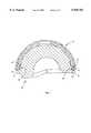
- FIG. 1is a cross-sectional view of an acetabular shell according to the present invention.
- FIG. 2is a top view of a bearing insert useful in connection with the acetabular shell of FIG. 1.
- FIG. 3is an elevational view of the bearing insert of FIG. 2.
- FIG. 4is a bottom view of the bearing insert of FIG. 2.
- FIG. 5is a cross-sectional view of the bearing insert of FIG. 2, taken in plane 5--5 of FIG. 2 and viewed in the direction of the arrows.
- FIG. 6is a perspective view of the bearing insert of FIG. 2.
- FIG. 7is a cross-sectional view of the bearing insert of FIG. 2 assembled to the acetabular shell of FIG. 1.
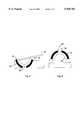
- FIG. 8is a schematic view of a test arrangement for evaluating the strength of the assembly of FIG. 7.
- FIG. 9is an alternate schematic view of a test arrangement for evaluating the strength of the assembly of FIG. 7.
- FIGS. 1-9a preferred embodiment of the present invention is illustrated in the form of an implantable orthopedic prosthesis, particularly an acetabular component of a total hip joint prosthesis.
- the illustrated acetabular componentis useful as part of that well-known type of total hip joint prosthesis that includes an acetabular component comprising an acetabular shell and an associated bearing liner, and a femoral component comprising a femoral stem and an associated spherical head.
- the spherical headfixed to the femoral stem, articulates in a ball-and-socket arrangement within the bearing liner, with the bearing liner being essentially fixed within the acetabular shell.
- the femoral stem and acetabular shellare fixed to bone of the proximal femur and pelvic acetabulum, respectively. Only the acetabular shell and bearing liner are described in detail herein, as the various types and configurations of femoral stems and heads are well understood in the art. The illustrated acetabular shell and bearing liner are particularly resistant to disconnection and displacement from each other when implanted.
- an acetabular shell 10is shown in cross-section in a plane along the axis of symmetry.
- Acetabular shell 10is shaped generally as a hemispherical cup having a shell wall 12 defined by a convex proximal surface 14 and a concave distal surface 16.
- Acetabular shell 10has a proximal dome region 18 at the apex of shell wall 12 and an annular rim 20 at the distal end of shell wall 12.
- Concave distal surface 16 of shell wall 12defines a shell cavity 22 having an opening 24 into and through which a bearing insert, described further below, can be received.
- An annular lip 25extends radially inwardly from concave distal surface 16 and, in cooperation with an annular protrusion on the bearing insert as described further below, provides a means for affixing the bearing insert against axial displacement from within shell cavity 22.
- Such meansalso includes an annular flange, described further below, on the bearing insert having notches for receiving the legs 26 that extend axially from rim 20. The interengagement of the legs 26 of shell 10 and the notches of the bearing insert flange affix the bearing insert against rotation within shell cavity 22 about the axis of symmetry 27 of acetabular shell 10 passing through the center of proximal dome region 18 at the apex of shell 10.
- Convex proximal surface 14is provided with a macro-texture comprising circumferential grooves 28 filled and covered with a porous coating 29 comprised of titanium powder sintered in place.
- the porous coating 29accepts the ingrowth or ongrowth of bone, and enhances adhesion of bone cement.
- the porous coating 29, while preferred,is not necessary for the understanding or practice of the present invention.
- acetabular shell 10includes a dome hole 30 centered in dome region 18 at the apex of shell 10 in coaxial alignment with axis 27. Dome hole 30 is internally threaded to serve as an engagement interface for an instrument (not shown) for holding and positioning acetabular shell 10 during implantation.
- an instrument(not shown) for holding and positioning acetabular shell 10 during implantation.
- an instrumentis used by the implanting physician to securely grasp the acetabular shell 10 and place it in the reamed acetabulum.
- Such an instrumentusually includes an elongate handle for controlling anteversion and adduction of the acetabular shell as it is implanted, and for transmitting axial driving forces to the shell.
- Acetabular shell 10can also be provided with a plurality of screw holes (not shown) through shell wall 12 between concave distal surface 16 and convex proximal surface 14.
- a bone screw(not shown), having a head and a threaded shank, can be inserted through a screw hole from within the shell cavity 22 and screwed into the pelvic bone underlying the acetabulum to secure acetabular shell 10 in place.
- fusty-conical wall portion 44is a second right-cylindrical wall portion 46.
- a shoulder 48extends radially inwardly, followed by a third right-cylindrical wall portion 50 that extends distally therefrom, Finally, a second fusty-conical wall portion 52 slopes distally and radially outwardly from wall portion 50. Shoulder 48, right-cylindrical wall portion 50, and second fusty-conical wall portion 52 together define the annular lip 25 first mentioned above.
- FIGS. 2, 3 and 4are top, side and bottom views, respectively of bearing insert 60
- FIG. 5is a cross-sectional view of the same
- FIG. 6is a perspective view of bearing insert 60.
- bearing insert 60is designed to fit congruently against concave distal surface 16 of acetabular shell 10, in order to minimize the opportunity for bearing insert 60 to flex under load that otherwise would be made possible by a significant gap between bearing insert 60 and acetabular shell 10.
- bearing liner 60is provided with an integral connection means proximate the rim thereof that engages the geometrical features of the acetabular shell 10 as described above.
- the connection meanswhile allowing ease of insertion as described further below, also results in a strong connection between bearing insert 60 and acetabular shell 10 that is highly resistant to dislocation, separation, or disengagement.
- Such strength of connectionis highly advantageous after implantation of the acetabular component because the bearing insert is often subjected to forces by the head and femoral stem components that, under some circumstances, tend toward dislodging the bearing insert from the acetabular shell, which could result in failure of the implanted component.
- bearing insert 60has includes a convex spherical wall portion 62 followed by a first right-cylindrical wall portion 64, and a next subsequent fusty-conical wall portion 66 that slopes distally and radially outwardly.
- fusty-conical wall portion 66is a second right-cylindrical wall portion 68.
- a second fusty-conical wall portion 70slopes distally and radially inwardly from wall portion 68, followed by a third right-cylindrical wall portion 72 that extends distally therefrom.
- annular rim 74extends radially and includes a lip 76 that extends upwardly (proximally) and radially outwardly.
- Fusty-conical wall portion 66, cylindrical wall portion 68, and fusty-conical wall portion 70together form an annular protrusion 78 that engages the annular groove 79 in shell 10, which is defined by fusty-conical wall surface 44, cylindrical wall surface 46, and shoulder 48 proximally of annular lip 25.
- annular protrusion 78is not continuously annular, but rather is periodically relieved about its circumference by a plurality of notches 80.
- annular protrusion 78As preferred, about fifty percent of the circumference of annular protrusion 78 is relieved by notches 80, evenly spaced. As shown best in FIGS. 2 and 4, annular rim 74, also is not continuously annular, but rather is periodically relieved about its circumference by a plurality of notches 82. As preferred, about twenty-five percent of the circumference of annular rim 74 is relieved by notches 82, evenly spaced.
- bearing insert 60is shown inserted within acetabular shell 10. Fusty-conical wall portion 70 of the annular protrusion 78 of bearing insert 60 engages shoulder 48 of acetabular shell 10 to retain bearing insert 60 therein.
- annular protrusion 78deforms elastically, as permitted by the relieved areas 80, in order to proceed past annular lip of shell 10. Once past, annular protrusion 78 rebounds into the annular groove 79 in shell 10.
- lip 76 of annular rim 74engages rim 20 of shell 10, and is elastically deformed distally, as permitted by relieved areas 82 and as shown best in FIG. 7. The deformed annular rim 74 maintains spring pressure against rim 20 via lip 76 to hold annular protrusion 78 tightly against shoulder 48 of shell 10.
- FIGS. 8 and 9a test arrangement is shown schematically, by which the resistance of bearing liner 60 against displacement from shell 10 is measured.
- a push out testis illustrated, whereas in FIG. 9, a lever out test is shown.
- the force required to dislodge bearing insert 60 from shell 10either by an axial force 90 or a levered force 92 about a fulcrum 94 near the rim 20 of the shell, the strength of the connection between bearing insert 60 and shell 10 can be characterized.
- the push out testwas performed on a 28 mm polyethylene insert fully seated in a 53 mm shell.
- the push out pin 96was moved axially at a linear velocity of 0.2 inches per minute until failure of the insert to shell connection.
- An axial load of about 750 lbswas required to dislodge the bearing insert 60.
- the lever armwas moved about the fulcrum at an angular velocity of 1.3 radians per minute at a fulcrum located 2.2 inches from the bearing liner, until failure of the insert to shell connection.
- a torque load of about 580 inch-poundswas required to dislodge the bearing insert.
Landscapes
- Health & Medical Sciences (AREA)
- Orthopedic Medicine & Surgery (AREA)
- Transplantation (AREA)
- Vascular Medicine (AREA)
- Oral & Maxillofacial Surgery (AREA)
- Engineering & Computer Science (AREA)
- Biomedical Technology (AREA)
- Heart & Thoracic Surgery (AREA)
- Cardiology (AREA)
- Life Sciences & Earth Sciences (AREA)
- Animal Behavior & Ethology (AREA)
- General Health & Medical Sciences (AREA)
- Public Health (AREA)
- Veterinary Medicine (AREA)
- Physical Education & Sports Medicine (AREA)
- Prostheses (AREA)
Abstract
Description
Claims (21)
Priority Applications (7)
| Application Number | Priority Date | Filing Date | Title |
|---|---|---|---|
| US08/962,163US5938702A (en) | 1997-10-31 | 1997-10-31 | Locking mechanism for acetabular cup |
| JP52642399AJP4057068B2 (en) | 1997-10-31 | 1998-10-27 | Lock mechanism for acetabular cup |
| EP98954011AEP0949891B1 (en) | 1997-10-31 | 1998-10-27 | Locking mechanism for acetabular cup |
| PCT/US1998/022733WO1999022674A1 (en) | 1997-10-31 | 1998-10-27 | Locking mechanism for acetabular cup |
| AU11236/99AAU1123699A (en) | 1997-10-31 | 1998-10-27 | Locking mechanism for acetabular cup |
| DE69820854TDE69820854T2 (en) | 1997-10-31 | 1998-10-27 | LOCKING DEVICE FOR HIP JOINT PAN |
| US09/226,556US6129765A (en) | 1997-10-31 | 1999-01-07 | Locking mechanism for acetabular cup |
Applications Claiming Priority (1)
| Application Number | Priority Date | Filing Date | Title |
|---|---|---|---|
| US08/962,163US5938702A (en) | 1997-10-31 | 1997-10-31 | Locking mechanism for acetabular cup |
Related Child Applications (1)
| Application Number | Title | Priority Date | Filing Date |
|---|---|---|---|
| US09/226,556ContinuationUS6129765A (en) | 1997-10-31 | 1999-01-07 | Locking mechanism for acetabular cup |
Publications (1)
| Publication Number | Publication Date |
|---|---|
| US5938702Atrue US5938702A (en) | 1999-08-17 |
Family
ID=25505500
Family Applications (2)
| Application Number | Title | Priority Date | Filing Date |
|---|---|---|---|
| US08/962,163Expired - LifetimeUS5938702A (en) | 1997-10-31 | 1997-10-31 | Locking mechanism for acetabular cup |
| US09/226,556Expired - LifetimeUS6129765A (en) | 1997-10-31 | 1999-01-07 | Locking mechanism for acetabular cup |
Family Applications After (1)
| Application Number | Title | Priority Date | Filing Date |
|---|---|---|---|
| US09/226,556Expired - LifetimeUS6129765A (en) | 1997-10-31 | 1999-01-07 | Locking mechanism for acetabular cup |
Country Status (6)
| Country | Link |
|---|---|
| US (2) | US5938702A (en) |
| EP (1) | EP0949891B1 (en) |
| JP (1) | JP4057068B2 (en) |
| AU (1) | AU1123699A (en) |
| DE (1) | DE69820854T2 (en) |
| WO (1) | WO1999022674A1 (en) |
Cited By (62)
| Publication number | Priority date | Publication date | Assignee | Title |
|---|---|---|---|---|
| US6129765A (en)* | 1997-10-31 | 2000-10-10 | Sulzer Orthopedics Inc. | Locking mechanism for acetabular cup |
| US6152961A (en)* | 1997-12-29 | 2000-11-28 | Depuy Orthopaedics, Inc. | Acetabular prosthesis assembly |
| US6290727B1 (en)* | 1998-09-24 | 2001-09-18 | GMT GESELLSCHAFT FüR MADIZINISCHE TECHNIK MBH | Acetabular cup |
| US6299647B1 (en)* | 1998-09-25 | 2001-10-09 | Biopro, Inc. | Snap-fitting, non-dislocating hip joint socket implant |
| WO2002007652A1 (en)* | 2000-07-20 | 2002-01-31 | Hayes Medical, Inc. | Bimetal acetabular component construct for hip joint prosthesis |
| US6488713B1 (en)* | 2001-04-25 | 2002-12-03 | Biomet, Inc. | Hip joint prosthesis with integral bearing extraction member |
| US6527809B1 (en)* | 1998-08-17 | 2003-03-04 | Doursounian Levon | Trial acetabulum or implantable acetabulum with adjustable orientation |
| US6626947B2 (en) | 2000-10-03 | 2003-09-30 | Depuy Orthopaedics, Inc. | Press fit acetabular cup and associated method for securing the cup to an acetabulum |
| US20030191537A1 (en)* | 2002-04-09 | 2003-10-09 | Wasielewski Ray C. | Biologically reabsorbable acetabular constraining components and materials for use with a hip replacement prosthesis and bioreabsorbable materials to augment hip replacement stability and function |
| US6652588B2 (en) | 2000-07-20 | 2003-11-25 | Hayes Medical, Inc. | Bimetal tibial component construct for knee joint prosthesis |
| US20040117029A1 (en)* | 2002-12-13 | 2004-06-17 | Lewis Paul P. | Modular orthopaedic implant apparatus and method |
| US20040193282A1 (en)* | 2003-03-31 | 2004-09-30 | Hanes Mark D. | Reduced wear orthopaedic implant apparatus and method |
| US6827742B2 (en)* | 1998-05-14 | 2004-12-07 | Daniel E. E. Hayes, Jr. | Bimetal acetabular component construct for hip joint prosthesis |
| WO2004069096A3 (en)* | 2003-01-31 | 2004-12-16 | Ortho Dev Corp | Polymeric acetabular cup |
| US20070106392A1 (en)* | 2005-11-08 | 2007-05-10 | Howmedica Osteonics Corp. | Acetabular cup locking mechanism |
| US7255712B1 (en) | 1997-04-15 | 2007-08-14 | Active Implants Corporation | Bone growth promoting implant |
| US20080053169A1 (en)* | 2006-08-30 | 2008-03-06 | Victoria Marie Ricker | Theft deterrent device for bags |
| US20080154369A1 (en)* | 2006-11-07 | 2008-06-26 | Barr George A | Medical implants |
| CN100418493C (en)* | 2003-03-13 | 2008-09-17 | 钱本文 | Natural innominatum devices |
| US7445640B2 (en) | 1998-05-14 | 2008-11-04 | Hayes Medical, Inc. | Implant with composite coating |
| US7445639B2 (en) | 2001-02-23 | 2008-11-04 | Biomet Manufacturing Corp. | Knee joint prosthesis |
| US20080294266A1 (en)* | 2007-05-21 | 2008-11-27 | Active Implants Corporation | Methods, Systems, and Apparatus for Implanting Prosthetic Devices Into Cartilage |
| US7497874B1 (en) | 2001-02-23 | 2009-03-03 | Biomet Manufacturing Corp. | Knee joint prosthesis |
| US7572295B2 (en) | 2001-12-04 | 2009-08-11 | Active Implants Corporation | Cushion bearing implants for load bearing applications |
| US7597715B2 (en) | 2005-04-21 | 2009-10-06 | Biomet Manufacturing Corp. | Method and apparatus for use of porous implants |
| US20090287311A1 (en)* | 2006-08-04 | 2009-11-19 | Roman Preuss | Asymmetric design of hip socket for reducing socket deformations |
| US7635447B2 (en) | 2006-02-17 | 2009-12-22 | Biomet Manufacturing Corp. | Method and apparatus for forming porous metal implants |
| US7758653B2 (en) | 2002-05-23 | 2010-07-20 | Active Implants Corporation | Implants |
| US20110015753A1 (en)* | 2009-07-14 | 2011-01-20 | Biomet Manufacturing Corp. | Multiple Bearing Acetabular Prosthesis |
| US20110087333A1 (en)* | 2006-11-07 | 2011-04-14 | Kellar Franz W | Prosthetic knee joint |
| US20110166667A1 (en)* | 2006-11-07 | 2011-07-07 | Kellar Franz W | Prosthetic ball-and-socket joint |
| US20110166671A1 (en)* | 2006-11-07 | 2011-07-07 | Kellar Franz W | Prosthetic joint |
| US7981160B1 (en)* | 2004-02-27 | 2011-07-19 | Serafin Jr Louis A | Multi-hooded enarthrodial joint implant cup and securement |
| US8021432B2 (en) | 2005-12-05 | 2011-09-20 | Biomet Manufacturing Corp. | Apparatus for use of porous implants |
| US8066778B2 (en) | 2005-04-21 | 2011-11-29 | Biomet Manufacturing Corp. | Porous metal cup with cobalt bearing surface |
| US8123815B2 (en) | 2008-11-24 | 2012-02-28 | Biomet Manufacturing Corp. | Multiple bearing acetabular prosthesis |
| US8123814B2 (en) | 2001-02-23 | 2012-02-28 | Biomet Manufacturing Corp. | Method and appartus for acetabular reconstruction |
| US8157869B2 (en) | 2007-01-10 | 2012-04-17 | Biomet Manufacturing Corp. | Knee joint prosthesis system and method for implantation |
| US8163028B2 (en) | 2007-01-10 | 2012-04-24 | Biomet Manufacturing Corp. | Knee joint prosthesis system and method for implantation |
| US20120116527A1 (en)* | 2009-04-24 | 2012-05-10 | DePul International Limited | Surgical prostheses |
| US8187280B2 (en) | 2007-10-10 | 2012-05-29 | Biomet Manufacturing Corp. | Knee joint prosthesis system and method for implantation |
| US8266780B2 (en) | 2005-04-21 | 2012-09-18 | Biomet Manufacturing Corp. | Method and apparatus for use of porous implants |
| US8292967B2 (en) | 2005-04-21 | 2012-10-23 | Biomet Manufacturing Corp. | Method and apparatus for use of porous implants |
| US8308812B2 (en) | 2006-11-07 | 2012-11-13 | Biomedflex, Llc | Prosthetic joint assembly and joint member therefor |
| US8328873B2 (en) | 2007-01-10 | 2012-12-11 | Biomet Manufacturing Corp. | Knee joint prosthesis system and method for implantation |
| US8512413B2 (en) | 2006-11-07 | 2013-08-20 | Biomedflex, Llc | Prosthetic knee joint |
| US8562616B2 (en) | 2007-10-10 | 2013-10-22 | Biomet Manufacturing, Llc | Knee joint prosthesis system and method for implantation |
| US8679187B2 (en) | 2006-03-20 | 2014-03-25 | Smith & Nephew, Inc. | Acetabular cup assembly for multiple bearing materials |
| US9005307B2 (en) | 2006-11-07 | 2015-04-14 | Biomedflex, Llc | Prosthetic ball-and-socket joint |
| US10258474B2 (en) | 2014-09-01 | 2019-04-16 | Jossi Holding Ag | Artificial joint cup |
| USD847997S1 (en)* | 2017-11-15 | 2019-05-07 | Joint Innovation Technology, Llc | Acetabular cup liner |
| US10307255B1 (en) | 2017-11-29 | 2019-06-04 | b-ONE Ortho, Corp. | Acetabular cup assembly |
| USD851764S1 (en)* | 2017-11-15 | 2019-06-18 | Joint Innovation Technology, Llc | Acetabular cup liner |
| USD851765S1 (en)* | 2017-11-15 | 2019-06-18 | Joint Innovation Technology, Llc | Acetabular cup liner |
| USD858768S1 (en)* | 2016-08-26 | 2019-09-03 | Surgical Device Innovations, LLC | Acetabular device |
| US11000378B2 (en) | 2017-02-14 | 2021-05-11 | Surgical Device Innovations, LLC | Acetabular surgical implant for segmental pelvic defect and methods of use and manufacture |
| USD919089S1 (en)* | 2017-11-15 | 2021-05-11 | Joint Innovation Technology, Llc. | Acetabular cup liner |
| USD922579S1 (en)* | 2017-11-15 | 2021-06-15 | Joint Innovation Technology, Llc. | Acetabular cup liner |
| US12053383B2 (en) | 2020-09-18 | 2024-08-06 | Globus Medical Inc. | Hip arthroplasty implants |
| US12083018B2 (en) | 2020-09-18 | 2024-09-10 | Globus Medical, Inc. | Hip arthroplasty implants |
| US12171666B2 (en) | 2019-12-10 | 2024-12-24 | Depuy Ireland Unlimited Company | Metal reinforced acetabular shell liner |
| US12274623B2 (en) | 2019-12-11 | 2025-04-15 | Depuy Ireland Unlimited Company | Ceramic acetabular shell liners with augments |
Families Citing this family (25)
| Publication number | Priority date | Publication date | Assignee | Title |
|---|---|---|---|---|
| JP2003526455A (en)* | 2000-03-14 | 2003-09-09 | スミス アンド ネフュー インコーポレーテッド | Acetabular shell liner with variable geometry rim surface |
| AU783205C (en)* | 2000-03-15 | 2006-08-17 | Depuy Orthopaedics, Inc. | Prosthetic cup assembly which includes components possessing self-locking taper |
| US20020116068A1 (en) | 2001-01-25 | 2002-08-22 | Mclean Terry | Containment system for constraining a prosthetic component |
| US7326253B2 (en)* | 2001-11-16 | 2008-02-05 | Depuy Products, Inc. | Prosthetic cup assembly having increased assembly congruency |
| US6916342B2 (en)* | 2002-04-01 | 2005-07-12 | Smith & Nephew, Inc. | Liner assembly for prosthetic components |
| US6986792B2 (en) | 2002-09-13 | 2006-01-17 | Smith & Nephew, Inc. | Prostheses |
| US20040209015A1 (en)* | 2003-04-15 | 2004-10-21 | Palitha Wickramanayake | Additives for use in print media to reduce bronzing |
| RU2240757C1 (en)* | 2003-07-02 | 2004-11-27 | Закрытое акционерное общество "ЭндоИмплант" | Endoprosthesis of hip joint cotyloid cavity |
| US7115145B2 (en)* | 2003-07-03 | 2006-10-03 | Zimmer, Inc. | Acetabular component |
| US7022142B2 (en) | 2003-07-03 | 2006-04-04 | Zimmer Austin, Inc. | Constrained acetabular liner |
| EP1722719B1 (en)* | 2004-03-11 | 2016-04-27 | Smith & Nephew, Inc | Universal liner assembly for joint replacement |
| US20060190089A1 (en)* | 2005-02-18 | 2006-08-24 | Howmedica Osteonics Corp. | Internal adaptor for hip acetabular cage |
| AU2006335005B2 (en)* | 2006-01-09 | 2009-09-24 | Silesco Pty Ltd | Implantable joint prosthesis |
| DE102007031666A1 (en) | 2006-08-04 | 2008-02-14 | Ceramtec Ag Innovative Ceramic Engineering | Asymmetric design of pans and / or cup inserts for manipulation and suppression of natural frequencies |
| US8979938B2 (en)* | 2007-11-08 | 2015-03-17 | Linares Medical Devices, Llc | Artificial knee implant including liquid ballast supporting / rotating surfaces and incorporating flexible multi-material and natural lubricant retaining matrix applied to a joint surface |
| WO2010129880A2 (en)* | 2009-05-07 | 2010-11-11 | Smith & Nephew, Inc. | Modular trial heads for a prosthetic |
| US10420648B2 (en)* | 2009-06-10 | 2019-09-24 | Jean-Pierre LAFFAY | Acetabular prosthetic system with simplified impaction |
| WO2012015945A2 (en)* | 2010-07-29 | 2012-02-02 | Mayo Foundation For Medical Education And Research | Acetabular cup prosthesis |
| US8398718B2 (en) | 2011-02-16 | 2013-03-19 | Rodney Ian Walter Richardson | Acetabular cup with rotatable bearing member |
| US8465549B2 (en) | 2011-02-16 | 2013-06-18 | Rodney Ian Walter Richardson | Acetabular cup with rotatable bearing |
| US9060862B2 (en) | 2011-07-08 | 2015-06-23 | Floyd Franklin Castro | Semi-constrained ball and socket joints |
| GB2551155A (en)* | 2016-06-07 | 2017-12-13 | Matortho Ltd | Prosthesis |
| US11583405B2 (en)* | 2017-03-13 | 2023-02-21 | Floyd G. Goodman | Hard substance multi-hooded enarthrodial joint implant |
| US11376128B2 (en)* | 2018-12-31 | 2022-07-05 | Depuy Ireland Unlimited Company | Acetabular orthopaedic prosthesis and method |
| US11419729B2 (en) | 2019-06-20 | 2022-08-23 | Northwell Health, Inc. | Constrained acetabular liner |
Citations (21)
| Publication number | Priority date | Publication date | Assignee | Title |
|---|---|---|---|---|
| US168140A (en)* | 1875-07-17 | 1875-09-28 | Improvement in artificial legs | |
| US453285A (en)* | 1891-03-23 | 1891-06-02 | Artificial leg | |
| US489258A (en)* | 1893-01-03 | George e | ||
| US492583A (en)* | 1893-02-28 | Artificial-leg attachment | ||
| US909859A (en)* | 1909-01-19 | John T Apgar | Artificial leg. | |
| US1216367A (en)* | 1915-07-16 | 1917-02-20 | James F Rowley | Artificial leg. |
| US1314136A (en)* | 1919-08-26 | Artificial leg | ||
| US1370299A (en)* | 1919-04-09 | 1921-03-01 | Robert N Flanagan | Artificial limb |
| US3863273A (en)* | 1973-09-20 | 1975-02-04 | Meditec Inc | Orthopedic prosthetic implant devices |
| US4285071A (en)* | 1979-07-02 | 1981-08-25 | Nelson Carl L | Method of securing a prosthesis using cement spacers |
| US4417571A (en)* | 1979-07-02 | 1983-11-29 | Nelson Carl L | Prosthetic cement spacer and method for using same |
| US4778474A (en)* | 1984-11-16 | 1988-10-18 | Homsy Charles A | Acetabular prosthesis |
| US5139526A (en)* | 1990-10-12 | 1992-08-18 | Wright & Filippis, Inc. | Long above elbow and elbow disartic prosthesis |
| US5181929A (en)* | 1989-03-23 | 1993-01-26 | Ceramiques Techniques Desmarquest | Femoral prosthesis employing a small ceramic ball |
| US5226918A (en)* | 1992-07-13 | 1993-07-13 | Howard Silagy | Prosthesis with adjustable fitting clearance |
| US5443519A (en)* | 1993-04-22 | 1995-08-22 | Implex Corporation | Prosthetic ellipsoidal acetabular cup |
| US5458650A (en)* | 1993-03-30 | 1995-10-17 | Tornier S.A. | Elastically deformable cotyloidal prosthesis |
| US5676704A (en)* | 1995-11-27 | 1997-10-14 | Smith & Nephew, Inc. | Acetabular cup body prosthesis |
| US5725591A (en)* | 1996-08-13 | 1998-03-10 | Johnson & Johnson Professional, Inc. | Acetabular bearing system |
| US5735901A (en)* | 1993-08-30 | 1998-04-07 | Sulzer Medizinaltechnik Ag | Element for temporarily increasing the rigidity of an orthopaedic prosthesis |
| US5766260A (en)* | 1995-06-06 | 1998-06-16 | Whiteside; Leo A. | Acetabular component with improved liner seal and lock |
Family Cites Families (16)
| Publication number | Priority date | Publication date | Assignee | Title |
|---|---|---|---|---|
| DE2340734A1 (en)* | 1973-08-11 | 1975-02-20 | Feldmuehle Anlagen Prod | ARTIFICIAL JOINT REPLACEMENT |
| GB1573608A (en)* | 1976-12-22 | 1980-08-28 | Howse & Co Ltd D | Prosthetic hip cup assembly |
| CA1240101A (en)* | 1983-05-06 | 1988-08-09 | Michael J. Pappas | Multi-component prosthesis with increased wall flexibility facilitating component assembly |
| DE8500869U1 (en)* | 1985-01-11 | 1985-12-19 | Mecron Medizinische Produkte Gmbh, 1000 Berlin | Artificial hip socket with a support element and a socket insert |
| CH673941A5 (en)* | 1987-10-28 | 1990-04-30 | Sulzer Ag | |
| GB8819589D0 (en)* | 1988-08-17 | 1988-09-21 | Minnesota Mining & Mfg | Acetabular component of hip joint prosthesis |
| FR2638963B1 (en)* | 1988-11-14 | 1991-01-04 | Tornier Sa | ARTIFICIAL COTYLES WITH ERGOTS FOR TOTAL HIP PROSTHESIS |
| FR2653326B1 (en)* | 1989-10-24 | 1994-09-16 | Favortho | TOTAL HIP PROSTHESIS. |
| ES2076891B1 (en)* | 1993-03-18 | 1996-08-16 | Levante Ind Quirurgicas | MODULAR COTILE. |
| US5480448A (en)* | 1993-09-20 | 1996-01-02 | Mikhail; W. E. Michael | Acetabular cup groove insert |
| US5658294A (en)* | 1993-12-02 | 1997-08-19 | Sulzer Orthopedics Inc. | Instrument for holding an acetabular cup |
| WO1995015734A1 (en)* | 1993-12-10 | 1995-06-15 | Intermedics Orthopedics, Inc. | Acetabular shell having screw holes with breakout seals |
| US5571198A (en)* | 1994-01-21 | 1996-11-05 | David A. Drucker | Acetabular shell with selectively available bone screw holds |
| US5782929A (en)* | 1996-12-31 | 1998-07-21 | Sulzer Orthopedics Inc. | Acetabular shell having sintered screw hole plugs |
| US5938702A (en)* | 1997-10-31 | 1999-08-17 | Sulzer Orthopedics Inc. | Locking mechanism for acetabular cup |
| US5935175A (en)* | 1998-03-13 | 1999-08-10 | Johnson & Johnson Professional, Inc. | Acetabular prosthesis with ring lock mechanism |
- 1997
- 1997-10-31USUS08/962,163patent/US5938702A/ennot_activeExpired - Lifetime
- 1998
- 1998-10-27WOPCT/US1998/022733patent/WO1999022674A1/enactiveIP Right Grant
- 1998-10-27EPEP98954011Apatent/EP0949891B1/ennot_activeExpired - Lifetime
- 1998-10-27JPJP52642399Apatent/JP4057068B2/ennot_activeExpired - Fee Related
- 1998-10-27DEDE69820854Tpatent/DE69820854T2/ennot_activeExpired - Lifetime
- 1998-10-27AUAU11236/99Apatent/AU1123699A/ennot_activeAbandoned
- 1999
- 1999-01-07USUS09/226,556patent/US6129765A/ennot_activeExpired - Lifetime
Patent Citations (22)
| Publication number | Priority date | Publication date | Assignee | Title |
|---|---|---|---|---|
| US489258A (en)* | 1893-01-03 | George e | ||
| US492583A (en)* | 1893-02-28 | Artificial-leg attachment | ||
| US909859A (en)* | 1909-01-19 | John T Apgar | Artificial leg. | |
| US1314136A (en)* | 1919-08-26 | Artificial leg | ||
| US168140A (en)* | 1875-07-17 | 1875-09-28 | Improvement in artificial legs | |
| US453285A (en)* | 1891-03-23 | 1891-06-02 | Artificial leg | |
| US1216367A (en)* | 1915-07-16 | 1917-02-20 | James F Rowley | Artificial leg. |
| US1370299A (en)* | 1919-04-09 | 1921-03-01 | Robert N Flanagan | Artificial limb |
| US3863273A (en)* | 1973-09-20 | 1975-02-04 | Meditec Inc | Orthopedic prosthetic implant devices |
| US4417571A (en)* | 1979-07-02 | 1983-11-29 | Nelson Carl L | Prosthetic cement spacer and method for using same |
| US4285071A (en)* | 1979-07-02 | 1981-08-25 | Nelson Carl L | Method of securing a prosthesis using cement spacers |
| US4778474A (en)* | 1984-11-16 | 1988-10-18 | Homsy Charles A | Acetabular prosthesis |
| US5181929A (en)* | 1989-03-23 | 1993-01-26 | Ceramiques Techniques Desmarquest | Femoral prosthesis employing a small ceramic ball |
| US5139526A (en)* | 1990-10-12 | 1992-08-18 | Wright & Filippis, Inc. | Long above elbow and elbow disartic prosthesis |
| US5226918A (en)* | 1992-07-13 | 1993-07-13 | Howard Silagy | Prosthesis with adjustable fitting clearance |
| US5458650A (en)* | 1993-03-30 | 1995-10-17 | Tornier S.A. | Elastically deformable cotyloidal prosthesis |
| US5443519A (en)* | 1993-04-22 | 1995-08-22 | Implex Corporation | Prosthetic ellipsoidal acetabular cup |
| US5549698A (en)* | 1993-04-22 | 1996-08-27 | Implex Corp. | Prosthetic acetabular cup and method of implant |
| US5735901A (en)* | 1993-08-30 | 1998-04-07 | Sulzer Medizinaltechnik Ag | Element for temporarily increasing the rigidity of an orthopaedic prosthesis |
| US5766260A (en)* | 1995-06-06 | 1998-06-16 | Whiteside; Leo A. | Acetabular component with improved liner seal and lock |
| US5676704A (en)* | 1995-11-27 | 1997-10-14 | Smith & Nephew, Inc. | Acetabular cup body prosthesis |
| US5725591A (en)* | 1996-08-13 | 1998-03-10 | Johnson & Johnson Professional, Inc. | Acetabular bearing system |
Non-Patent Citations (3)
| Title |
|---|
| Benjamin I. Rosner, Paul D. Postak, A. Seth Greenwald; Cup/Liner Incongruity of Two Piece Acetabular Designs: Implications in the Generation of Polyethylene Debris.* |
| Michael J. Wentz, Harry E. Rubash, Arun S. Shanbhag; Evaluation of Micromotion of the Inter Op Acetabular System.* |
| Michael J. Wentz, Harry E. Rubash, Arun S. Shanbhag; Evaluation of Micromotion of the Inter-Op Acetabular System. |
Cited By (99)
| Publication number | Priority date | Publication date | Assignee | Title |
|---|---|---|---|---|
| US7255712B1 (en) | 1997-04-15 | 2007-08-14 | Active Implants Corporation | Bone growth promoting implant |
| US6129765A (en)* | 1997-10-31 | 2000-10-10 | Sulzer Orthopedics Inc. | Locking mechanism for acetabular cup |
| US6152961A (en)* | 1997-12-29 | 2000-11-28 | Depuy Orthopaedics, Inc. | Acetabular prosthesis assembly |
| US20050102034A1 (en)* | 1998-05-14 | 2005-05-12 | E. Hayes Daniel E.Jr. | Bimetal acetabular component construct for hip joint prosthesis |
| US7850738B2 (en)* | 1998-05-14 | 2010-12-14 | Hayes Jr Daniel E E | Bimetal acetabular component construct for hip joint prosthesis |
| US7445640B2 (en) | 1998-05-14 | 2008-11-04 | Hayes Medical, Inc. | Implant with composite coating |
| US7513912B2 (en) | 1998-05-14 | 2009-04-07 | Hayes Medical, Inc. | Bimetal tibial component construct for knee joint prosthesis |
| US20080021565A1 (en)* | 1998-05-14 | 2008-01-24 | Hayes Daniel E E Jr | Bimetal tibial component construct for knee joint prosthesis |
| US7189262B2 (en) | 1998-05-14 | 2007-03-13 | Hayes Medical, Inc. | Bimetal tibial component construct for knee joint prosthesis |
| US6827742B2 (en)* | 1998-05-14 | 2004-12-07 | Daniel E. E. Hayes, Jr. | Bimetal acetabular component construct for hip joint prosthesis |
| US20110295381A1 (en)* | 1998-05-14 | 2011-12-01 | Hayes Jr Daniel E E | Bimetal acetabular component construct for hip joint prosthesis |
| US8167954B2 (en) | 1998-05-14 | 2012-05-01 | Consensus Orthopedics, Inc. | Implant with composite coating |
| US6527809B1 (en)* | 1998-08-17 | 2003-03-04 | Doursounian Levon | Trial acetabulum or implantable acetabulum with adjustable orientation |
| US6290727B1 (en)* | 1998-09-24 | 2001-09-18 | GMT GESELLSCHAFT FüR MADIZINISCHE TECHNIK MBH | Acetabular cup |
| US6299647B1 (en)* | 1998-09-25 | 2001-10-09 | Biopro, Inc. | Snap-fitting, non-dislocating hip joint socket implant |
| WO2002007652A1 (en)* | 2000-07-20 | 2002-01-31 | Hayes Medical, Inc. | Bimetal acetabular component construct for hip joint prosthesis |
| US6652588B2 (en) | 2000-07-20 | 2003-11-25 | Hayes Medical, Inc. | Bimetal tibial component construct for knee joint prosthesis |
| US6626947B2 (en) | 2000-10-03 | 2003-09-30 | Depuy Orthopaedics, Inc. | Press fit acetabular cup and associated method for securing the cup to an acetabulum |
| US8551181B2 (en) | 2001-02-23 | 2013-10-08 | Biomet Manufacturing, Llc | Method and apparatus for acetabular reconstruction |
| US9375316B2 (en) | 2001-02-23 | 2016-06-28 | Biomet Manufacturing, Llc. | Method and apparatus for acetabular reconstruction |
| US8123814B2 (en) | 2001-02-23 | 2012-02-28 | Biomet Manufacturing Corp. | Method and appartus for acetabular reconstruction |
| US7497874B1 (en) | 2001-02-23 | 2009-03-03 | Biomet Manufacturing Corp. | Knee joint prosthesis |
| US7445639B2 (en) | 2001-02-23 | 2008-11-04 | Biomet Manufacturing Corp. | Knee joint prosthesis |
| US6488713B1 (en)* | 2001-04-25 | 2002-12-03 | Biomet, Inc. | Hip joint prosthesis with integral bearing extraction member |
| US7572295B2 (en) | 2001-12-04 | 2009-08-11 | Active Implants Corporation | Cushion bearing implants for load bearing applications |
| EP2145604A1 (en) | 2001-12-04 | 2010-01-20 | Active Implants Corporation | Cushion bearing implants for load bearing applications |
| US8814946B2 (en) | 2001-12-04 | 2014-08-26 | Active Implants Corporation | Cushion bearing implants for load bearing applications |
| US20030191537A1 (en)* | 2002-04-09 | 2003-10-09 | Wasielewski Ray C. | Biologically reabsorbable acetabular constraining components and materials for use with a hip replacement prosthesis and bioreabsorbable materials to augment hip replacement stability and function |
| US6923833B2 (en) | 2002-04-09 | 2005-08-02 | Ray C. Wasielewski | Biologically reabsorbable acetabular constraining components and materials for use with a hip replacement prosthesis and bioreabsorbable materials to augment hip replacement stability and function |
| US7758653B2 (en) | 2002-05-23 | 2010-07-20 | Active Implants Corporation | Implants |
| US20110077745A1 (en)* | 2002-12-13 | 2011-03-31 | Depuy Products, Inc. | Prosthesis Implantation Method |
| US20040117029A1 (en)* | 2002-12-13 | 2004-06-17 | Lewis Paul P. | Modular orthopaedic implant apparatus and method |
| US8597364B2 (en) | 2002-12-13 | 2013-12-03 | DePuy Synthes Products, LLC | Prosthesis implantation method |
| US7846212B2 (en) | 2002-12-13 | 2010-12-07 | Depuy Products, Inc. | Modular orthopaedic implant apparatus |
| US6926740B2 (en)* | 2002-12-13 | 2005-08-09 | Depuy Products, Inc. | Modular orthopaedic implant apparatus and method |
| US7402177B2 (en) | 2003-01-31 | 2008-07-22 | Ortho Development Corporation | Polymeric acetabular cup |
| US20050261777A1 (en)* | 2003-01-31 | 2005-11-24 | Ortho Development Corporation | Polymeric acetabular cup |
| WO2004069096A3 (en)* | 2003-01-31 | 2004-12-16 | Ortho Dev Corp | Polymeric acetabular cup |
| CN100418493C (en)* | 2003-03-13 | 2008-09-17 | 钱本文 | Natural innominatum devices |
| US20040193282A1 (en)* | 2003-03-31 | 2004-09-30 | Hanes Mark D. | Reduced wear orthopaedic implant apparatus and method |
| US7108720B2 (en)* | 2003-03-31 | 2006-09-19 | Depuy Products, Inc. | Reduced wear orthopaedic implant apparatus and method |
| US7981160B1 (en)* | 2004-02-27 | 2011-07-19 | Serafin Jr Louis A | Multi-hooded enarthrodial joint implant cup and securement |
| US8197550B2 (en) | 2005-04-21 | 2012-06-12 | Biomet Manufacturing Corp. | Method and apparatus for use of porous implants |
| US8292967B2 (en) | 2005-04-21 | 2012-10-23 | Biomet Manufacturing Corp. | Method and apparatus for use of porous implants |
| US8266780B2 (en) | 2005-04-21 | 2012-09-18 | Biomet Manufacturing Corp. | Method and apparatus for use of porous implants |
| US7597715B2 (en) | 2005-04-21 | 2009-10-06 | Biomet Manufacturing Corp. | Method and apparatus for use of porous implants |
| US8066778B2 (en) | 2005-04-21 | 2011-11-29 | Biomet Manufacturing Corp. | Porous metal cup with cobalt bearing surface |
| US20070106392A1 (en)* | 2005-11-08 | 2007-05-10 | Howmedica Osteonics Corp. | Acetabular cup locking mechanism |
| US8021432B2 (en) | 2005-12-05 | 2011-09-20 | Biomet Manufacturing Corp. | Apparatus for use of porous implants |
| US7635447B2 (en) | 2006-02-17 | 2009-12-22 | Biomet Manufacturing Corp. | Method and apparatus for forming porous metal implants |
| US8679187B2 (en) | 2006-03-20 | 2014-03-25 | Smith & Nephew, Inc. | Acetabular cup assembly for multiple bearing materials |
| US8888861B2 (en)* | 2006-08-04 | 2014-11-18 | Ceramtec Gmbh | Asymmetric design of hip socket for reducing socket deformations |
| US20090287311A1 (en)* | 2006-08-04 | 2009-11-19 | Roman Preuss | Asymmetric design of hip socket for reducing socket deformations |
| US20080053169A1 (en)* | 2006-08-30 | 2008-03-06 | Victoria Marie Ricker | Theft deterrent device for bags |
| US8512413B2 (en) | 2006-11-07 | 2013-08-20 | Biomedflex, Llc | Prosthetic knee joint |
| US9005306B2 (en) | 2006-11-07 | 2015-04-14 | Biomedflex, Llc | Medical Implants With Compliant Wear-Resistant Surfaces |
| US8029574B2 (en) | 2006-11-07 | 2011-10-04 | Biomedflex Llc | Prosthetic knee joint |
| US8070823B2 (en) | 2006-11-07 | 2011-12-06 | Biomedflex Llc | Prosthetic ball-and-socket joint |
| US9107754B2 (en) | 2006-11-07 | 2015-08-18 | Biomedflex, Llc | Prosthetic joint assembly and prosthetic joint member |
| US20110166671A1 (en)* | 2006-11-07 | 2011-07-07 | Kellar Franz W | Prosthetic joint |
| US20110166667A1 (en)* | 2006-11-07 | 2011-07-07 | Kellar Franz W | Prosthetic ball-and-socket joint |
| US20110087333A1 (en)* | 2006-11-07 | 2011-04-14 | Kellar Franz W | Prosthetic knee joint |
| US8308812B2 (en) | 2006-11-07 | 2012-11-13 | Biomedflex, Llc | Prosthetic joint assembly and joint member therefor |
| US9005307B2 (en) | 2006-11-07 | 2015-04-14 | Biomedflex, Llc | Prosthetic ball-and-socket joint |
| US20080154369A1 (en)* | 2006-11-07 | 2008-06-26 | Barr George A | Medical implants |
| US9566157B2 (en) | 2006-11-07 | 2017-02-14 | Biomedflex, Llc | Three-member prosthetic joint |
| US8936648B2 (en) | 2007-01-10 | 2015-01-20 | Biomet Manufacturing, Llc | Knee joint prosthesis system and method for implantation |
| US8157869B2 (en) | 2007-01-10 | 2012-04-17 | Biomet Manufacturing Corp. | Knee joint prosthesis system and method for implantation |
| US8480751B2 (en) | 2007-01-10 | 2013-07-09 | Biomet Manufacturing, Llc | Knee joint prosthesis system and method for implantation |
| US8163028B2 (en) | 2007-01-10 | 2012-04-24 | Biomet Manufacturing Corp. | Knee joint prosthesis system and method for implantation |
| US8328873B2 (en) | 2007-01-10 | 2012-12-11 | Biomet Manufacturing Corp. | Knee joint prosthesis system and method for implantation |
| US7780740B2 (en)* | 2007-05-21 | 2010-08-24 | Active Implants Corporation | Methods, systems, and apparatus for implanting prosthetic devices into cartilage |
| US20080294266A1 (en)* | 2007-05-21 | 2008-11-27 | Active Implants Corporation | Methods, Systems, and Apparatus for Implanting Prosthetic Devices Into Cartilage |
| US10736747B2 (en) | 2007-10-10 | 2020-08-11 | Biomet Manufacturing, Llc | Knee joint prosthesis system and method for implantation |
| US8187280B2 (en) | 2007-10-10 | 2012-05-29 | Biomet Manufacturing Corp. | Knee joint prosthesis system and method for implantation |
| US9763793B2 (en) | 2007-10-10 | 2017-09-19 | Biomet Manufacturing, Llc | Knee joint prosthesis system and method for implantation |
| US8562616B2 (en) | 2007-10-10 | 2013-10-22 | Biomet Manufacturing, Llc | Knee joint prosthesis system and method for implantation |
| US8123815B2 (en) | 2008-11-24 | 2012-02-28 | Biomet Manufacturing Corp. | Multiple bearing acetabular prosthesis |
| US9445903B2 (en) | 2008-11-24 | 2016-09-20 | Biomet Manufacturing, Llc | Multi-bearing acetabular prosthesis |
| US8979939B2 (en) | 2009-04-24 | 2015-03-17 | Depuy International Limited | Surgical prostheses |
| US20120116527A1 (en)* | 2009-04-24 | 2012-05-10 | DePul International Limited | Surgical prostheses |
| US8894717B2 (en)* | 2009-04-24 | 2014-11-25 | Depuy International Limited | Surgical prostheses |
| US8308810B2 (en) | 2009-07-14 | 2012-11-13 | Biomet Manufacturing Corp. | Multiple bearing acetabular prosthesis |
| US9445904B2 (en) | 2009-07-14 | 2016-09-20 | Biomet Manufacturing, Llc | Multiple bearing acetabular prosthesis |
| US20110015753A1 (en)* | 2009-07-14 | 2011-01-20 | Biomet Manufacturing Corp. | Multiple Bearing Acetabular Prosthesis |
| US10258474B2 (en) | 2014-09-01 | 2019-04-16 | Jossi Holding Ag | Artificial joint cup |
| USD858768S1 (en)* | 2016-08-26 | 2019-09-03 | Surgical Device Innovations, LLC | Acetabular device |
| US11559404B2 (en) | 2017-02-14 | 2023-01-24 | Onkos Surgical, Inc. | Acetabular surgical implant for segmental pelvic defect and methods of use and manufacture |
| US11000378B2 (en) | 2017-02-14 | 2021-05-11 | Surgical Device Innovations, LLC | Acetabular surgical implant for segmental pelvic defect and methods of use and manufacture |
| USD851764S1 (en)* | 2017-11-15 | 2019-06-18 | Joint Innovation Technology, Llc | Acetabular cup liner |
| USD851765S1 (en)* | 2017-11-15 | 2019-06-18 | Joint Innovation Technology, Llc | Acetabular cup liner |
| USD919089S1 (en)* | 2017-11-15 | 2021-05-11 | Joint Innovation Technology, Llc. | Acetabular cup liner |
| USD922579S1 (en)* | 2017-11-15 | 2021-06-15 | Joint Innovation Technology, Llc. | Acetabular cup liner |
| USD847997S1 (en)* | 2017-11-15 | 2019-05-07 | Joint Innovation Technology, Llc | Acetabular cup liner |
| US10307255B1 (en) | 2017-11-29 | 2019-06-04 | b-ONE Ortho, Corp. | Acetabular cup assembly |
| US12171666B2 (en) | 2019-12-10 | 2024-12-24 | Depuy Ireland Unlimited Company | Metal reinforced acetabular shell liner |
| US12274623B2 (en) | 2019-12-11 | 2025-04-15 | Depuy Ireland Unlimited Company | Ceramic acetabular shell liners with augments |
| US12053383B2 (en) | 2020-09-18 | 2024-08-06 | Globus Medical Inc. | Hip arthroplasty implants |
| US12083018B2 (en) | 2020-09-18 | 2024-09-10 | Globus Medical, Inc. | Hip arthroplasty implants |
Also Published As
| Publication number | Publication date |
|---|---|
| EP0949891A1 (en) | 1999-10-20 |
| AU1123699A (en) | 1999-05-24 |
| JP4057068B2 (en) | 2008-03-05 |
| EP0949891B1 (en) | 2004-01-02 |
| DE69820854D1 (en) | 2004-02-05 |
| WO1999022674A1 (en) | 1999-05-14 |
| JP2001507273A (en) | 2001-06-05 |
| US6129765A (en) | 2000-10-10 |
| DE69820854T2 (en) | 2004-06-09 |
Similar Documents
| Publication | Publication Date | Title |
|---|---|---|
| US5938702A (en) | Locking mechanism for acetabular cup | |
| US5876456A (en) | Implantable prosthesis having interference-locked hole plugs | |
| EP0394545B1 (en) | Stepped-lock ring system for implantable joint prostheses | |
| US6908486B2 (en) | Modular acetabular anti-protrusio cage and porous ingrowth cup combination | |
| US7338528B2 (en) | Humeral stem with anatomical location of taper access for fixation of humeral head | |
| US6126694A (en) | Universal distal broach and stem trial | |
| US6926740B2 (en) | Modular orthopaedic implant apparatus and method | |
| US7713306B2 (en) | Method and apparatus for acetabular reconstruction | |
| EP0137040B2 (en) | Ball and socket bearing for artificial joint | |
| US7291177B2 (en) | Method and apparatus for acetabular reconstruction | |
| US6458161B1 (en) | Method and apparatus for acetabular reconstruction | |
| US11712340B2 (en) | Hemi arthroplasty joint implant | |
| US20020147499A1 (en) | Locking systems for implants | |
| US20050246031A1 (en) | Line assembly for prosthetic components | |
| US20110054628A1 (en) | Reflex fixation geometry revision and reconstruction system reverse articulation | |
| EP1411868A2 (en) | Method and apparatus for use of a metal-metal constrained liner | |
| WO2008063500A1 (en) | Extended range of motion, constrained prosthetic hip-joint | |
| US6120546A (en) | Implantable prosthesis having spring-engaged hole plugs | |
| US5935174A (en) | Acetabular shell having flexible dome hole diaphragm | |
| US20230027395A1 (en) | Anchoring member for a joint replacement | |
| EP4284306A1 (en) | Rotatable hip prosthesis | |
| HK1067293A1 (en) | Modular acetabular cup | |
| HK1067293B (en) | Modular acetabular cup |
Legal Events
| Date | Code | Title | Description |
|---|---|---|---|
| AS | Assignment | Owner name:SULZER ORTHOPEDICS INC., TEXAS Free format text:ASSIGNMENT OF ASSIGNORS INTEREST;ASSIGNOR:LOPEZ, JORGE;REEL/FRAME:009175/0443 Effective date:19971121 Owner name:SULZER ORTHOPEDICS INC., TEXAS Free format text:ASSIGNMENT OF ASSIGNORS INTEREST;ASSIGNOR:VAN DER MEULEN, STEVE;REEL/FRAME:009169/0785 Effective date:19971217 | |
| STCF | Information on status: patent grant | Free format text:PATENTED CASE | |
| AS | Assignment | Owner name:UBS AG, STAMFORD BRANCH AS SECURITY AGENT FOR THE Free format text:SECURITY INTEREST;ASSIGNORS:CENTERPULSE ORTHOPEDICS INC.;CENTERPULSE USA HOLDING CO., CORPORATION, DELAWARE;CENTERPULSE USA INC., CORPORATION, DELAWARE;AND OTHERS;REEL/FRAME:013467/0328 Effective date:20021029 | |
| AS | Assignment | Owner name:CENTERPULSE ORTHOPEDICS INC., TEXAS Free format text:CHANGE OF NAME;ASSIGNOR:SULZER ORTHOPEDICS INC.;REEL/FRAME:013516/0549 Effective date:20020930 | |
| FPAY | Fee payment | Year of fee payment:4 | |
| AS | Assignment | Owner name:CENTERPULSE USA INC., TEXAS Free format text:PATENT RELEASE AGREEMENT;ASSIGNOR:UBS AG, STAMFORD BRANCH;REEL/FRAME:014699/0404 Effective date:20031002 | |
| AS | Assignment | Owner name:ZIMMER AUSTIN, INC., TEXAS Free format text:CHANGE OF NAME;ASSIGNOR:CENTERPULSE ORTHOPEDICS INC.;REEL/FRAME:016263/0264 Effective date:20040602 | |
| AS | Assignment | Owner name:ZIMMER, INC., INDIANA Free format text:CHANGE OF NAME;ASSIGNOR:ZIMMER AUSTIN, INC.;REEL/FRAME:017435/0714 Effective date:20060208 | |
| FPAY | Fee payment | Year of fee payment:8 | |
| FPAY | Fee payment | Year of fee payment:12 |