US5938692A - Voltage controlled variable tuning antenna - Google Patents
Voltage controlled variable tuning antennaDownload PDFInfo
- Publication number
- US5938692A US5938692AUS08/621,634US62163496AUS5938692AUS 5938692 AUS5938692 AUS 5938692AUS 62163496 AUS62163496 AUS 62163496AUS 5938692 AUS5938692 AUS 5938692A
- Authority
- US
- United States
- Prior art keywords
- antenna
- impedance
- coaxial cable
- catheter
- variable
- Prior art date
- Legal status (The legal status is an assumption and is not a legal conclusion. Google has not performed a legal analysis and makes no representation as to the accuracy of the status listed.)
- Expired - Lifetime
Links
- 239000004020conductorSubstances0.000claimsabstractdescription37
- 239000012212insulatorSubstances0.000claimsabstractdescription23
- 238000002560therapeutic procedureMethods0.000claimsdescription31
- 230000002441reversible effectEffects0.000claimsdescription12
- 230000001419dependent effectEffects0.000claims7
- 230000005855radiationEffects0.000abstractdescription19
- 238000004804windingMethods0.000abstractdescription3
- 210000001519tissueAnatomy0.000description62
- XLYOFNOQVPJJNP-UHFFFAOYSA-NwaterSubstancesOXLYOFNOQVPJJNP-UHFFFAOYSA-N0.000description37
- 210000003708urethraAnatomy0.000description36
- 238000001816coolingMethods0.000description35
- 239000003990capacitorSubstances0.000description28
- 210000002307prostateAnatomy0.000description23
- 206010004446Benign prostatic hyperplasiaDiseases0.000description15
- 208000004403Prostatic HyperplasiaDiseases0.000description15
- 210000002700urineAnatomy0.000description15
- 238000004861thermometryMethods0.000description12
- 238000000034methodMethods0.000description11
- 239000012809cooling fluidSubstances0.000description7
- 238000010438heat treatmentMethods0.000description7
- 230000000903blocking effectEffects0.000description6
- 239000002826coolantSubstances0.000description6
- 238000010276constructionMethods0.000description5
- 238000013461designMethods0.000description5
- 238000010586diagramMethods0.000description5
- 210000000664rectumAnatomy0.000description5
- 239000012530fluidSubstances0.000description4
- 238000003780insertionMethods0.000description4
- 230000037431insertionEffects0.000description4
- 229920002529medical grade siliconePolymers0.000description4
- 210000000056organAnatomy0.000description4
- 210000004197pelvisAnatomy0.000description4
- 229920001296polysiloxanePolymers0.000description4
- 229910000679solderInorganic materials0.000description4
- 230000007704transitionEffects0.000description4
- 206010020843HyperthermiaDiseases0.000description3
- 230000000694effectsEffects0.000description3
- 210000003204ejaculatory ductAnatomy0.000description3
- 230000036031hyperthermiaEffects0.000description3
- 238000004519manufacturing processMethods0.000description3
- 229920002401polyacrylamidePolymers0.000description3
- 229920000260silasticPolymers0.000description3
- 230000002485urinary effectEffects0.000description3
- 208000027418Wounds and injuryDiseases0.000description2
- 238000012937correctionMethods0.000description2
- 238000010168coupling processMethods0.000description2
- 238000005859coupling reactionMethods0.000description2
- 238000009826distributionMethods0.000description2
- 238000009472formulationMethods0.000description2
- 230000006870functionEffects0.000description2
- 230000001939inductive effectEffects0.000description2
- 238000007915intraurethral administrationMethods0.000description2
- 239000000203mixtureSubstances0.000description2
- 238000012544monitoring processMethods0.000description2
- 230000036961partial effectEffects0.000description2
- 230000008569processEffects0.000description2
- 239000002904solventSubstances0.000description2
- 230000008467tissue growthEffects0.000description2
- 208000037157AzotemiaDiseases0.000description1
- 206010048994Bladder spasmDiseases0.000description1
- RYGMFSIKBFXOCR-UHFFFAOYSA-NCopperChemical compound[Cu]RYGMFSIKBFXOCR-UHFFFAOYSA-N0.000description1
- 206010020524HydronephrosisDiseases0.000description1
- 206010021639IncontinenceDiseases0.000description1
- 206010028980NeoplasmDiseases0.000description1
- 206010030113OedemaDiseases0.000description1
- 206010036018PollakiuriaDiseases0.000description1
- 206010046555Urinary retentionDiseases0.000description1
- 230000001154acute effectEffects0.000description1
- 239000000853adhesiveSubstances0.000description1
- 230000001070adhesive effectEffects0.000description1
- 230000002411adverseEffects0.000description1
- 230000004075alterationEffects0.000description1
- 230000009286beneficial effectEffects0.000description1
- 230000002146bilateral effectEffects0.000description1
- 238000009529body temperature measurementMethods0.000description1
- 201000011510cancerDiseases0.000description1
- 239000000919ceramicSubstances0.000description1
- 230000008859changeEffects0.000description1
- 238000013500data storageMethods0.000description1
- 239000008367deionised waterSubstances0.000description1
- 229910021641deionized waterInorganic materials0.000description1
- 206010013990dysuriaDiseases0.000description1
- 230000003028elevating effectEffects0.000description1
- 230000005284excitationEffects0.000description1
- 239000000835fiberSubstances0.000description1
- 230000009931harmful effectEffects0.000description1
- 210000001624hipAnatomy0.000description1
- 230000000670limiting effectEffects0.000description1
- 238000004020luminiscence typeMethods0.000description1
- 230000014759maintenance of locationEffects0.000description1
- 239000000463materialSubstances0.000description1
- 230000002956necrotizing effectEffects0.000description1
- 206010029446nocturiaDiseases0.000description1
- 238000013021overheatingMethods0.000description1
- 210000003899penisAnatomy0.000description1
- 230000035699permeabilityEffects0.000description1
- 238000002360preparation methodMethods0.000description1
- 238000004886process controlMethods0.000description1
- 238000005086pumpingMethods0.000description1
- 238000011084recoveryMethods0.000description1
- 230000002829reductive effectEffects0.000description1
- 238000005057refrigerationMethods0.000description1
- 239000000523sampleSubstances0.000description1
- 239000007787solidSubstances0.000description1
- 230000002459sustained effectEffects0.000description1
- 208000024891symptomDiseases0.000description1
- 238000007669thermal treatmentMethods0.000description1
- 208000019206urinary tract infectionDiseases0.000description1
- 210000001835visceraAnatomy0.000description1
Images


Classifications
- A—HUMAN NECESSITIES
- A61—MEDICAL OR VETERINARY SCIENCE; HYGIENE
- A61B—DIAGNOSIS; SURGERY; IDENTIFICATION
- A61B18/00—Surgical instruments, devices or methods for transferring non-mechanical forms of energy to or from the body
- A61B18/18—Surgical instruments, devices or methods for transferring non-mechanical forms of energy to or from the body by applying electromagnetic radiation, e.g. microwaves
- A61B18/1815—Surgical instruments, devices or methods for transferring non-mechanical forms of energy to or from the body by applying electromagnetic radiation, e.g. microwaves using microwaves
Definitions
- the present inventionrelates to the field of microwave thermal therapy of tissue.
- the present inventionrelates to a catheter for transurethral microwave thermal therapy of benign prostatic hyperplasia (BPH).
- BPHbenign prostatic hyperplasia
- the prostate glandis a complex, chestnut-shaped organ which encircles the urethra immediately below the bladder.
- This relatively small organwhich is the most frequently diseased of all internal organs, is the site of a common affliction among older men, benign prostatic hyperplasia (BPH), as well as a more serious affliction, cancer.
- BPHis a nonmalignant, bilateral nodular tumorous expansion of prostate tissue occurring mainly in the transition zone of the prostate. Left untreated, BPH causes obstruction of the urethra which usually results in increased urinary frequency, urgency, incontinence, nocturia and slow or interrupted urinary stream. BPH may also result in more severe complications, such as urinary tract infection, acute urinary retention, hydronephrosis and uraemia.
- a fairly recent treatment method for BPHinvolves microwave thermal therapy, in which microwave energy is employed to elevate the temperature of tissue surrounding the prostatic urethra above about 45° C., thereby thermally damaging the tumorous BPH tissue.
- Delivery of microwave energy to tumorous prostatic tissueis generally accomplished by a microwave antenna-containing applicator, which is positioned within a body cavity adjacent the prostate gland.
- the microwave antennawhen energized, heats adjacent tissue due to molecular excitation and generates a cylindrically symmetrical radiation pattern which encompasses and necroses the tumorous prostatic tissue.
- the necrosed intraprostatic tissueis subsequently reabsorbed by the body, thereby relieving an individual from the symptoms of BPH.
- a safer and more effective treatment of BPHis transurethral microwave thermal therapy.
- This method of treatmentminimizes the distance between a microwave antenna-containing applicator and the transition zone of the prostate by positioning a Foley-type catheter-bearing applicator adjacent to the prostate gland within the urethra. Due to the close proximity of the microwave antenna to the prostate, a lesser volume of tissue is exposed to the cylindrically symmetrical radiation pattern generated by the microwave antenna, thereby minimizing the amount of healthy tissue necrosed.
- Intraurethral applicators of the type describedcan be found in Turner et al. U.S. Pat. No. 4,967,765 and Hascoet et al. European Patent Application 89403199.6.
- transurethral catheterssuch as that described in Rudie U.S. Pat. No. 5,413,588, issued May 9, 1995, include shafts having a multiplicity of lumens arranged about a lumen carrying a microwave antenna.
- the antenna lumenis oriented nearer a first side of the catheter shaft than a second side of the catheter shaft to position the microwave radiation closer to the first side of the catheter.
- Cooling lumensare arranged about the microwave antenna lumen to absorb a portion of the microwave radiation so that a greater amount of microwave radiation is absorbed on a second side of the catheter shaft than the first side.
- This arrangementcreates an asymmetrical microwave radiation pattern to permit focusing a greater amount of microwave radiation toward a selected tissue, such as prostatic tissue anterior and lateral to the urethra.
- This transurethral catheter designalso includes a lumen to facilitate urinary drainage from the bladder through the urethra during a treatment session.
- Antennas which have been used for hyperthermiahave a variety of inadequacies which preclude their application to microwave thermal therapy.
- Such antennasoften generate heat in two forms: microwave energy and heat energy due to resistive losses of the antenna.
- the efficiency of these antennashas not been of much concern due to the relatively low amount of energy used to generate interstitial temperatures of between about 43° C. to 45° C. and the lack of any adverse effect these temperatures had on healthy tissue.
- the shape and size of a radiation pattern generated by some microwave antennasare in part a function of how deeply the antenna is inserted into the tissue.
- the objective of microwave thermal therapyis to reduce the length of a treatment session and to selectively heat and necrose only undesirous tissue, while sparing, to the greatest extent possible, adjacent healthy tissue.
- the ability to eliminate resistive losses and utilize only microwave energy to heat a targeted tissue areawill permit a cooling system, such as that described in co-owned application Ser. No. 07/847,718, now U.S. Pat. No.
- the present inventionis an improved helical dipole antenna for thermal treatment of interstitial tissues.
- the helical antennais carried by a coaxial cable which has an outer insulator, an outer conductor, an inner insulator and an inner conductor.
- the coaxial cable and antennaare in turn carried by a catheter.
- a mid-point of the helical antennais connected to the outer conductor of the coaxial cable so as to form first and second helical sections of approximately equal length.
- a voltage controlled series capacitanceis connected between the coaxial cable and the helical antenna.
- the voltage controlled capacitanceis connected between the inner conductor of the coaxial cable and a point on the second helical section.
- a control voltagecauses the voltage controlled capacitance to match a resistive component of impedance of the antenna with a characteristic impedance of the coaxial cable. This match minimizes reflective losses of the antenna, thereby maximizing power transferred to the antenna.
- the reflective losses of the antennaare monitored and the control voltage adjusted to maintain the reflective losses at a minimum level.
- FIG. 1is a vertical sectional view of a male pelvic region showing the urinary organs affected by benign prostatic hyperplasia.
- FIG. 2Ais a side view of the distal end of the urethral catheter of the present invention.
- FIG. 2Bis an enlarged sectional view of the proximal end of the urethral catheter of the present invention.
- FIG. 3is a cross-sectional view of the urethral catheter of FIG. 2B taken along line 3--3.
- FIG. 4is a perspective view of a proximal region of the urethral catheter with the end portion taken in section from line 4--4 of FIG. 2B.
- FIG. 5is an enlarged view of the male pelvic region of FIG. 1 showing the urethral catheter of the present invention positioned within the prostate region.
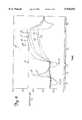
- FIG. 6is a graph illustrating temperature distribution generated by the catheter of the present invention as a function of time.
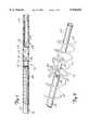
- FIG. 7is a partial sectional view of the microwave antenna of the urethral catheter of the present invention.
- FIG. 8is an exploded view of the microwave antenna shown in FIG. 7.
- FIG. 9is a block diagram of the transurethral microwave thermal therapy system of the present invention.
- FIG. 10is a schematic diagram of an alternative embodiment of the present invention.
- FIG. 11is a block diagram of the alternative transurethral microwave thermal therapy system of FIG. 10.
- FIG. 1is a vertical sectional view of a male pelvic region showing the effect benign prostatic hyperplasia (BPH) has on the urinary organs.
- Urethra 10is a duct leading from bladder 12, through prostate 14 and out orifice 16 of penis end 18. Benign tumorous tissue growth within prostate 14 around urethra 10 causes constriction 20 of urethra 10, which interrupts the flow of urine from bladder 12 to orifice 16.
- the tumorous tissue of prostate 14 which encroaches urethra 10 and causes constriction 20can be effectively removed by heating and necrosing the encroaching tumorous tissue.
- periurethral tumorous tissue of prostate 14 anterior and lateral to urethra 10is heated and necrosed to avoid unnecessary and undesirous damage to urethra 10 and to adjacent healthy tissues, such as ejaculatory duct 24 and rectum 26.
- a selective heating of benign tumorous tissue of prostate 14is made possible by microwave antenna-containing catheter 28 of the present invention, which is shown in FIGS. 2A and 2B.
- FIG. 2Ashows a side view of a distal end of catheter 28.
- FIG. 2Bshows an enlarged sectional view of a proximal end of catheter 28.
- catheter 28generally includes multi-port manifold 30, multi-lumen shaft 32, shaft position retention balloon 34, connection manifold 35, cooling system 36 and microwave generating source 38.
- Manifold 30includes inflation port 40, urine drainage port 42, microwave antenna port 44, cooling fluid in port 46 and cooling fluid out port 48. Ports 40-48 communicate with corresponding lumens within shaft 32. Manifold 30 is preferably made of medical-grade silicone sold by Dow Corning under the trademark Silastic Q-7-4850.
- Shaft 32is connected to manifold 30 at shaft distal end 50.
- Shaft 32is a multi-lumen, Foley-type urethral catheter shaft which is extruded from a flexible, medical-grade silicone sold by Dow Corning under the trademark Silastic Q-7-4850.
- Shaft 32which has an outer diameter of about 16 French, includes outer surface 52, which is generally elliptical in cross-section as shown in FIG. 3.
- Shaft 32is long enough to permit insertion of proximal shaft end 54 through urethra 10 and into bladder 12.
- shaft 32is coated with a hydrophilic solution sold by Hydromer, Inc. under the mark Hydromer, which lubricates outer surface 52 of shaft 32 and facilitates its advancement within urethra 10.
- shaft 32includes temperature sensing lumen 56, microwave antenna lumen 58, urine drainage lumen 60, balloon inflation lumen 62, cooling fluid intake lumens 64A and 64B, and cooling fluid exhaust lumens 66A and 66B.
- Lumens 56-66Bgenerally extend from distal shaft end 50 to proximal shaft end 54.
- multi-lumen shaft 32is also contemplated and may include different or modified cross-sections from that shown in FIGS. 2B-4.
- An example of an alternative embodiment of multi-lumen shaft 32is shown and described in co-pending U.S. patent application Ser. No. 08/469,201, filed Jun. 6, 1995, and is hereby incorporated by reference.
- temperature sensing lumen 56is positioned near first side 68 of shaft 32. Temperature sensing lumen 56 communicates with microwave antenna port 44 and permits insertion of thermometry sensor 69 within shaft 32 to monitor the temperature of surrounding tissue when shaft 32 is inserted within urethra 10. Sensor 69 exits through port 44 and is connected through connection manifold 35 to urethral thermometry unit 178B (shown in FIG. 9). In a preferred embodiment, thermometry sensor 69 is a fiber optic luminescence type temperature sensor sold by Luxtron Corporation. Temperature sensing lumen 56 is sealed at proximal end 54 by silicone plug 70.
- Microwave antenna lumen 58is eccentric to the longitudinal axis of shaft 32, antenna lumen 58 being positioned nearer first side 68 of shaft 32 than second side 72 of shaft 32.
- Antenna lumen 58is sealed at proximal end 54 by silicone plug 70A. At its distal end, antenna lumen 58 communicates with microwave antenna port 44.
- Microwave antenna 74is permanently positioned within antenna lumen 58 near balloon 34.
- Antenna 74is positioned within antenna lumen 58 so as to be generally situated adjacent the benign tumorous tissue of prostate 14 when shaft 32 is properly positioned within urethra 10. As shown in FIGS. 2A-2B, antenna 74 is bonded within antenna lumen 58 by adhesive bond 75.
- Antenna 74is carried at the proximal-most end of coaxial cable 76.
- the distal-most end of coaxial cable 76is connected to connection manifold 35 by a conventional quick-coupling fitting 73.
- Coaxial cable 76communicates with microwave generating source 38 by connection cable 76A, which is connected between microwave generating source 38 by connection manifold 35.
- connection cable 76Ais a standard RG 400 coaxial cable.
- Microwave generating source 38produces a maximum of 100 watts of electrical power at about 915 MHz frequency, +/-13 MHz, which is within the FCC-ISM standards.
- antenna 74When antenna 74 is energized by microwave generating source 38, antenna 74 emits electromagnetic energy which causes heating of tissue within prostate 14.
- Urine drainage lumen 60is positioned adjacent antenna lumen 58, between antenna lumen 58 and second side 72. Urine drainage lumen 60 communicates with urine drainage port 42 and defines a drainage path for urine when proximal end 54 of shaft 32 is inserted within bladder 12. Urine drainage lumen 60 is connected to urine drainage lumen extension 78 at proximal end 54. Urine drainage lumen extension 78 is bonded within proximal end cap 80. End cap 80 is further bonded over outer surface 52 of shaft 32 at proximal shaft end 54, with cavity 82 surrounding lumen extension 78. With end cap 80 and urine drainage lumen extension 78 in place, opening 84 to lumen extension 78 permits urine to drain port 42 when proximal shaft end 54 is inserted within bladder 12. Drainage of urine from bladder 12 is necessary due to frequent bladder spasms which occur during transurethral thermal therapy.
- Balloon inflation lumen 62is positioned near second side 72, generally between urine drainage lumen 60 and second side 72. Balloon inflation lumen 62 communicates with inflation port 40 and is sealed at proximal end 54 by silicone plug 70B. Balloon inflation lumen 62 communicates with interior 86 of balloon 34 by opening 88.
- Balloon 34which is formed from a tubular section of a flexible, medical-grade silicone sold by Dow Corning under the trademark Silastic Q-7-4720, is secured over shaft 32 by bonding balloon waists 90 and 92 over exterior surface 52 of shaft 32 near proximal shaft end 54. Balloon 34 is inflated by an inflation device 188 (shown in FIG. 9), which is connected to inflation port 40 and which supplies positive fluid pressure to interior 86 of balloon 34. Balloon 34 is deflated when inflation device 188 supplies a negative fluid pressure (i.e., a vacuum) to interior 86 of balloon 34. Balloon 34 serves to retain shaft 32 in a fixed position within urethra 10 when balloon 34 is inflated within bladder 12 near bladder neck 22, as shown in FIG. 5.
- cooling fluid intake lumens 64A, 64Bare positioned circumjacent first side 68, between first side 68 and antenna lumen 58. Cooling fluid intake lumens 64A, 64B extend from distal shaft end 50 to proximal shaft end 54 where lumens 64A, 64B are exposed to cavity 82 of end cap 80. Intake lumens 64A, 64B are relatively narrow in cross-section and have a relatively small cross-sectional surface area. Water contained within intake lumens 64A, 64B absorbs some of the microwave energy emitted by antenna 74. This assists, in part, in controlling the volume of tissue adjacent first side 68 of shaft 32 that is heated above about 45° C.
- the water within lumens 64A, 64Babsorbs heat energy generated by the microwave energy from adjacent tissues (i.e., urethra 10) via thermal conduction. This prevents the portion of urethra 10 adjacent first side 68 from being overheated and damaged when antenna 74 is energized.
- Cooling fluid exhaust lumens 66A, 66Bare circumjacent second side 72 with lumens 66A, 66B generally positioned between second side 72 and antenna lumen 58. Like intake lumens 64A, 64B, exhaust lumens 66A, 66B extend from shaft distal end 50 to shaft proximal end 54 where exhaust lumens 66A, 66B are exposed to cavity 82 of end cap 80. Exhaust lumens 66A, 66B are wider in cross-section than intake lumens 64A, 64B, and have a cross-sectional area greater than the cross-sectional area of intake lumens 64A, 64B.
- Water within exhaust lumens 66A, 66Bis therefore capable of absorbing a greater amount of microwave energy when antenna 74 is energized. As a result, for a given power output from microwave generating source 38, the temperature of tissue adjacent second side 72 will remain below about 45° C. Water within exhaust lumens 66A, 66B also absorbs heat energy from adjacent tissue (i.e., urethra 10) when antenna 74 is energized, which prevents the portion of urethra 10 adjacent second side 72 from being overheated and damaged when antenna 74 is energized.
- adjacent tissuei.e., urethra
- Intake lumens 64A, 64B and exhaust lumens 66A, 66Bare supplied with deionized water from cooling system 36.
- Water from cooling system 36is chilled to between about 12-15° C. and pumped at a rate of between about 100-150 milliliters per minute via water feed line 94A to connection manifold 35.
- water from cooling system 36may be chilled to between about 1-15° C. and pumped at a rate of between about 25-250 milliliters per minutes via water feed line 94A to connection manifold 35, as described in co-pending U.S. patent application Ser. No. 08/309,137, filed Sep. 20, 1994, which is hereby incorporated by reference.
- connection manifold 35to water feed line 94B and to water intake port 46, which communicates with water intake lumens 64A, 64B. Under fluid pressure, the water circulates through intake lumens 64A, 64B to cavity 82 of end cap 80. The water returns to cooling system 36 through exhaust lumens 66A, 66B to fluid exhaust port 48. The water is carried from water exhaust port 48 via water return line 96B to connection manifold 35, and from connection manifold 35 to cooling system 36 via water return line 96A. The water is then re-chilled and re-circulated.
- Water feed line 94A and water return line 96Bare each provided with a conventional quick-coupling fitting 65A and 65B, respectively, which permits catheter 28 to be easily disconnected from cooling system 36.
- FIG. 5shows an enlarged view of the male pelvic region of FIG. 1 with catheter 28 properly positioned within urethra 10.
- Orientation stripe 98 along exterior surface 52 on first side 68, as shown in FIG. 4,ensures the proper orientation of shaft 32 within urethra 10.
- shaft 32is positioned within urethra 10 with second side 72 of shaft 32 oriented toward rectum 26.
- Water exhaust lumens 66A, 66Bare oriented posteriorly, toward rectum 26 and water lumens 64A, 64b are oriented anteriorly toward fibromuscular tissue 100 of prostate 14.
- the portion of transition zone 101 anterior and lateral to urethra 10is the most frequent location of the tumorous tissue growth which causes BPH.
- water exhaust lumens 66A, 66Bare capable of absorbing more microwave energy than water intake lumens 64A, 64B, the radiation patterns created by microwave energy emitted from antenna 74 are asymmetrical.
- a relatively large volume of tissue enveloping the anterior portion of transition zone 101, adjacent first side 68is heated to a temperature above about 45° C., which effectively necroses the tumorous tissue of prostate 14 which encroaches upon urethra 10.
- the temperature of tissue adjacent second side 72remains below about 45° C., thereby eliminating the harmful effects of the microwave energy to ejaculatory duct 24 and rectum 26.
- FIG. 6is a graph which generally demonstrates a microwave thermal therapy procedure and a temperature distribution which was generated by catheter 28 of the present invention, with shaft 32 inserted into a polyacrylamide gel formulation which simulates biological tissue.
- the formulation and preparation procedures for the polyacrylamide gelare discussed in detail in D. Andreuccetti, M. Bini, A. Ignesti, R. Olmi, N. Rubino, and R. Vanni, Use of Polyacrylamide as a Tissue-Equivalent Material in the Microwave Range, 35 IEEE TRANSACTION ON BIOMEDICAL ENGINEERING 275 (No. 4, April 1988).
- FIG. 6shows temperature measurements taken from eight temperature sensors. Four sensors were aligned at fixed distances adjacent first side 68. Sensor 1A was positioned immediately adjacent shaft 32; sensor 1B was positioned about 0.66 cm from shaft 32; sensor 1C was positioned about 1.33 cm from shaft 32; and sensor 1D was positioned about 2.0 cm from shaft 32.
- Sensor 2Awas positioned immediately adjacent shaft 32; sensor 2B was positioned about 0.66 cm from shaft 32; sensor 2C was positioned about 1.33 cm from shaft 32; and sensor 2D was positioned about 2.0 cm from shaft 32.
- the x-axisrepresents a relative period of time over which the microwave thermal therapy procedure was performed.
- the y-axisrepresents temperature in degrees Celsius, with horizontal line H representing 45° C. (the temperature at or above which cells are necrosed.)
- the microwave thermal therapy procedure of the present inventionincludes five operating phases, P1-P5.
- Lines 1A-1D and 2A-2Dcorrespond with sensors 1A-1D and 2A-2D, respectfully.
- first phase P1cooling system 36 is turned on and chilled water is pumped through cooling lumens 64A, 64B and 66A, 66B.
- a drop in temperature immediately adjacent shaft 32is represented by lines 1A, 2A.
- cooling system 36is turned off.
- a relatively small amount of power(about 5 watts) is applied to microwave antenna 74.
- the temperature immediately adjacent shaft 32rises asymmetrically due to the greater absorptivity of water in the larger exhaust lumens 66A, 66B on second side 72, as shown by lines 1A, 2A.
- the poweris applied long enough to merely warm adjacent tissue to about 40° C.
- temperaturesgenerally return to base line temperature.
- the tissue responses to the chilling during P1 and the heating during P2aid in determining the vascularity of the tissue to be treated. This information aids in determining the amount of power necessary to treat tumorous tissue of prostate 14.
- cooling system 36is again turned on thereby pumping chilled water through cooling lumens 64A-66B.
- the temperature immediately adjacent shaft 32correspondingly drops as indicated by lines 1A, 2A. Prechilling of the tissue immediately adjacent shaft 32 aids in protecting the tissues immediately adjacent shaft 32 (i.e., urethra 10) from overheating due to a relatively rapid application of power from antenna 74.
- Microwave generating source 38is again turned on at the beginning of fourth phase P4 at a sustained power output of about 20 watts.
- temperatures adjacent second side 72represented by lines 2A-2D
- temperatures adjacent first side 68represented by lines 1A-1D.
- the temperature differentialsare most profound within a target volume of tissue 0.66 cm from shaft 32. Within this target volume, as shown by lines 1A, 2A and 1B, 2B, the difference in temperature from first side 68 and second side 72 is on the order of about 10° C.
- tissue within 45° C., while tissue within 0.66 cm of second side 72can remain at temperatures substantially below 45° C.
- tissue-necrosing temperatures within the target volumeare essentially restricted only to tissue near first side 68, which is the most frequent location of periurethral tumorous prostatic tissue.
- a relatively small volume of tissue adjacent second side 72can be heated above about 45° C. to necrose some of the tumorous prostatic tissue which is posterior and lateral to the urethra.
- microwave generating source 38is operated for at least about 45 minutes.
- the temperature of tissue immediately adjacent shaft 32(which is representative of temperatures of urethra 10), as well as temperatures of tissue beyond 0.66 cm from shaft 32, as shown by lines 1C, 2C and 1D, 2D, are maintainable well below 45° C. This is accomplished by adjusting cooling system parameters and, if necessary, power output from microwave generating source 38.
- cooling system 36continues to operate, circulating water through cooling lumens 64A-66B. A temperature drop immediately adjacent shaft 32 is relatively rapid as shown by lines 1A, 2A within P5.
- cooling system 36continues to operate for a period of time (on the order of 10 to 120 minutes) after the procedure to cool urethra 10 and reduce edema resulting from the application of heat to the periurethral tissues of prostate 14.
- water feed line 94B, water return line 96B and thermometry sensor 69are disconnected from connection manifold 35.
- Water feed line 94B and water return line 96B of catheter 28are then connected to another cooling system similar to cooling system 36 and water is then circulated through cooling lumens 64A-66B in a manner similar to that previously described. In this fashion, recovery from the previously described procedure can be accomplished away from the treatment area thereby enabling microwave generating source 38 and cooling system 36 to be readily available for treatment of another patient.
- FIG. 7shows a partial sectional view of microwave antenna 74 of the present invention.
- Antenna 74is positioned at a proximal-most end of shielded coaxial cable 76.
- Cable 76is a standard RG 178U coaxial cable and includes inner conductor 120, inner insulator 122, outer conductor 124, and outer insulator 126.
- Outer insulator 126, outer conductor 124 and inner insulator 122are stripped away to expose about 3 millimeters of outer conductor 124, about 1 millimeter of inner insulator 126 and about 1 millimeter of inner conductor 120.
- Capacitor 128includes first end 130, which is connected to antenna 74. Capacitor 128 serves to counteract a reactive component of antenna 74, thereby providing a 50 ohm match between coaxial cable 76 and microwave generating source 38, and antenna 74.
- capacitor 128is replaced with a tubular-shaped capacitor (not shown).
- a tubular-shaped capacitoris described in co-owned U.S. Pat. No. 5,370,677, issued Dec. 6, 1994, which is hereby incorporated by reference.
- Tubular extension 134which is a hollow section of outer insulator 126 of coaxial cable 76, is positioned over capacitor 128 and the exposed length of inner insulator 122 and secured by bond 136.
- Tubular extension 134includes hole 138, which provides an exit for second end 132 of capacitor 128.
- Wound about outer insulator 126 and tubular extension 134is flat wire 140.
- Flat wire 140is a single piece of flat copper wire with dimensions of about 0.009 inch by about 0.032 inch in cross-section, which provides a relatively large surface area for maximum current flow while minimizing the cross-sectional size of antenna 74.
- FIG. 8is an exploded view of a portion of antenna 74 which shows its helical dipole construction.
- the efficiency of any dipole antennais greatest when the effective electrical length of the antenna is generally one half the wavelength of the radiation emitted in the surrounding medium. Accordingly, a relatively efficient simple dipole antenna, operating at about 915 MHz, would require a physical length of about 8 centimeters which, according to the present invention, would needlessly irradiate and damage healthy tissue. Furthermore, the physical length of a relatively efficient simple dipole antenna operating at about 915 MHz cannot be varied.
- first and second wire sections 142 and 144are each comprised of eight, equally-spaced windings of flat wire 140.
- the combined length of first and second wire sections 142 and 144, and hence the overall length of antenna 74ranges from about 1.5 centimeters to about 4.0 centimeters, and varies according to the length of the area of prostate 14 which requires treatment.
- a standard medical-grade silicone tube(not shown), which has been allowed to soak in a solvent, such as Freon, is positioned over first and second wire sections 142 and 144. As the solvent evaporates, the silicone tube shrinks, thereby securing flat wire 140 to outer insulator 126 and tubular extension 134.
- a solventsuch as Freon
- antenna 74allows antenna 74 to range in physical length from about 1.5 to 4 centimeters, while electrically behaving like an eight centimeter-long simple dipole antenna.
- antenna 74has an effective electrical length generally equal to one half of the wavelength of the radiation emitted in the surrounding medium, independent of its physical length.
- the surrounding mediumincludes the catheter shaft and the surrounding tissue. This is a accomplished by varying the number and pitch of the windings of first and second wire sections 142 and 144.
- a family of catheters, which contain relatively efficient helical dipole antennas of different physical lengths,permits selection of the antenna best suited for the particular treatment area.
- antenna 74 of the present inventionis capable of producing a constant heating pattern in tissue, concentrated about antenna 74, independent of the depth of insertion into the tissue.
- Tap point 148is a point at which the resistive component of the combined impedance of first wire section 142 and second wire section 144 matches the characteristic impedance of coaxial cable 76.
- the impedance Zvaries from a low value at solder point 146 to a high value at a point farthest from solder point 146.
- This inductive componentcan be canceled by inserting a series capacitance, such as capacitor 128, which has a value of -jX ohms. This results in an impedance match of 50 ohms real.
- the resulting method of feeding antenna 74is commonly called gamma matching.
- tap point 148is about 3.5 turns from solder point 146 on second wire section 144.
- the value of capacitor 128is about 2.7pF.
- the helical dipole construction of antenna 74achieves a relatively small size, which permits intraurethral application.
- the helical dipole constructionis also responsible for three features which enable antenna 74 to achieve greater efficiency than prior known interstitial microwave antennas: good impedance matching, good current carrying capability and an effective electrical length which is generally one half of the wavelength of the radiation emitted in the surrounding medium, independent of the physical length of antenna 74.
- the good impedance match between antenna 74 and inner conductor 120minimizes reflective losses of antenna 74, with measured reflective losses of less than 1% in a preferred embodiment.
- the use of flat ribbon wire 140 for first wire section 142 and second wire section 144minimizes resistive losses of antenna 74 by providing a greater surface area upon which RF current can be carried.
- the helical dipole design of antenna 74has an effective electrical length which is generally one half of the wavelength of the radiation emitted in the surrounding medium, independent of the physical length of antenna 74. This permits the physical length of antenna 74 to be varied to accommodate varying sizes of individual prostates while maintaining the same efficient, effective electrical length of antenna 74.
- an efficient microwave antennais critical to the ability to focus thermal energy a distance from the antenna within a target volume.
- An inefficient antennaproduces a lesser intensity of microwave radiation within the target volume than desired. It also produces undesired heat close to the urethra, which will damage the urethra if not carried away by an increased coolant flow.
- This added burden on the cooling systemreduces its capacity to protect the urethra, thereby limiting the microwave power that can be radiated without elevating urethra temperatures above safety limits. With microwave power limited by cooling system capacity, the heat delivered to the desired target area of the prostate will not be sufficient for effective therapy.
- the efficient helical dipole design of antenna 74 of the present inventionensures that almost all heat delivered during the treatment is delivered in the form of microwave energy, rather than conductive heat energy.
- FIG. 9is a block diagram of transurethral microwave thermal therapy system 170, with which urethral catheter 28 is used.
- System 170includes cooling system 36 microwave generating source 38, user interface 172, real time controller (RTC) 174, directional coupler 176, thermometry sensors 182 and 184, coolant pressure sensor 186, balloon inflation device 188, and urine collection container 190.
- RTCreal time controller
- control of microwave generating source 38 and cooling system 36is affected by real time controller 174, which is in turn controlled by user interface 172.
- User interface 172is an IBM compatible machine including a hard drive and a solid state memory device for data storage.
- User interface 172communicates with RTC 174, which is responsible for all closed loop feedback to run system 170.
- RTC 174has direct closed loop control of microwave power from microwave generating source 38, and coolant flow and coolant temperature of cooling system 36. The closed loop feedback tracks out variations in gain, drift and cable losses inherent in microwave generating source 38, and variability in pump output and refrigeration system efficiency of cooling system 36.
- RTC 174In addition to monitoring microwave generating source 38 and cooling system 36, RTC 174 also monitors and controls several channels of thermometry via inputs from thermometry unit 178.
- Cooling system thermometry 178Ameasures the coolant and chiller temperatures based upon signals from coolant temperatures sensors 182 and 184 and a chiller temperature sensor (not shown) of cooling system 36.
- Urethral thermometry 178Bmeasures urethral temperature based upon signals from temperature sensor 69 within catheter 28.
- Rectal thermometry 178Cmeasures rectal temperature based upon signals received from a sensor (not shown) within rectal probe 180.
- RTC 174transmits all closed-loop feedback to user interface 172, which processes the input and transmits corrections and instructions back to RTC 174.
- RTC 174interprets the instructions given to it by process control language received from user interface 172 and executes the instructions in real time. All corrections from user interface 172 are made to maintain a given thermal profile throughout the transurethral thermal therapy.
- system 170includes a hardware fail-safe circuit which shuts down system 170 should any parameter fall outside a given range of values.
- FIG. 10schematically illustrates an impedance matching means 200 used in another embodiment of antenna 74.
- Impedance matching means 200provides a variable and controllable capacitance for aiding capacitor 128 in counteracting the reactive component of antenna 74.
- Variable impedance matching means 200allows the impedance of microwave generating source 38, coaxial cable 76, and antenna 74 to be accurately matched throughout the thermal therapy process. As noted above, accurate impedance matching allows the antenna's reflected power to be minimized.
- a variable and controllable capacitanceis desired for several reasons.
- a variable and controllable capacitanceallows greater manufacturing variability to be tolerated in antenna 74, coaxial cable 76, microwave generating source 38, and catheter 28, for example. Greater tolerances lower the manufacturing expense, but the increased tolerances in antenna 74, coaxial cable 76, microwave generating source 38, and catheter 28, for example, also introduce variations in the impedance of the system.
- a variable and controllable capacitancecan help compensate for the variations in impedance created by greater manufacturing tolerances. Also, as the microwave thermal therapy progresses, the resistivity and permeability characteristics of the tissue change, thereby affecting the impedance match between of antenna 74 and coaxial cable 76.
- a variable and controllable capacitanceis helpful in maintaining the impedance match between the antenna 74 and the coaxial 76.
- the impedance match between antenna 74 and coaxial cable 76may be adjusted by altering the frequency of the energy supplied to antenna 74.
- the range of adjustment for accurately matching the impedance of antenna 74 and coaxial cable 76 in this manneris limited by the acceptable range of frequencies for microwave thermal therapy.
- the adjustment range made available by altering the frequencymay not always be sufficient to accurately match the impedance of antenna 74 and coaxial cable 76, particularly if the use of a single frequency or narrow frequency range is desired. It is therefore desirable to extend the range of adjustment by other means.
- variable impedance matching means 200improves the ability to "tune" antenna 74 and match ;the impedance of antenna 74 to coaxial cable 76.
- Variable impedance matching means 200may be used together with frequency alteration to extend the range of adjustment provided by altering the frequency of the microwave energy supplied to antenna 74.
- variable impedance matching means 200may be use alone to match the impedance of antenna 74 and coaxial cable 76, especially where it is desired to use a single frequency during the therapy.
- Impedance matching means 200is preferably a reverse biased diode 202 connected in parallel with capacitor 128 between antenna 74 and inner conductor 120 of coaxial cable 76.
- Reverse biased diode 202can be a varactor diode, a pin diode, or other diode capable of acting in reverse biased fashion. Suitable diodes, for examples, are square ceramic MELFs available from Alpha Industries, Inc., of Woburn, Me. under part numbers A60030P535, A60033P535 and A60036P535.
- Reverse biased diode 202provides a voltage dependant capacitance which may be altered by changing the external voltage which is applied to the diode 202.
- reverse biased diode 202has a capacitance range sufficient to accommodate catheter and patient variability.
- impedance matching means 200is preferably located at, or as close as possible to antenna 74 to aid in obtaining an accurate impedance match between antenna 74 and coaxial cable 76.
- impedance matching means 200By locating impedance matching means 200 at, or close to antenna 74, a more accurate impedance match may be obtained.
- impedance matching 2000remotely from antenna 74 if a less accurate impedance match is acceptable.
- impedance matching means 200may be located near manifold 30, rather than near antenna 74. It may be desired to locate variable impedance matching means 200 remotely from antenna 74 if the size of variable impedance matching means 200 prohibits its location within catheter 28.
- variable impedance matching means 200as used in parallel with capacitor 128, it is also contemplated that the variable impedance matching means 200 be used as the only impedance matching means (i.e., without capacitor 128). If a variable impedance matching means 200 has a capacitance of sufficient size, there is no need for additional capacitor 128. The use of capacitor 128 and variable impedance matching means 200 in parallel may be required if, for example, variable impedance matching means 200 does not have a capacitance large enough to match the impedance of antenna 74 to coaxial cable 76.
- FIG. 11is a block diagram of transurethral microwave thermal therapy system 170.
- System 170 as shown FIG. 11is similar to system 170 as shown in FIG. 9, except for the inclusion of variable impedance matching means 200 as described above.
- FIG. 11shows the use of reverse biased diode 202 and the components necessary for altering the capacitance of diode 202. Therefore, like components in FIGS. 9 and 11 are identically numbered, and no additional description of the common components is provided.
- a voltage generator 204 connected to inner conductor 120 of coaxial cable 76provides a control voltage for altering the capacitance of reverse biased diode 202.
- the d.c. control signal from voltage generator 204is superimposed over the microwave power signal applied to coaxial cable 76, such that no additional cables or wires are required.
- voltage generator 204 and microwave generating source 38must be isolated from each other such that the d.c. signal from voltage generator 204 cannot reach microwave generating source 38, and such that the microwave power signal from microwave generating source 38 cannot reach voltage generator 204.
- Voltage generator 204 and microwave generating source 38are isolated by providing blocking capacitor 206, RF choke 208, and decoupling capacitor 210 as shown in FIG. 11.
- the d.c. signal from voltage generator 204sees blocking capacitor 206 and decoupling capacitor 210 as open circuits, while it sees RF choke 208 as a short circuit.
- the d.c. signalthus cannot travel past blocking capacitor 206 and decoupling capacitor 210, but may travel through RF choke 208.
- the microwave power signalsees blocking capacitor 206 and decoupling capacitor 210 as short circuits, while RF choke 208 appears as an open circuit.
- the microwave power signalthus can travel through blocking capacitor 206 and decoupling capacitor 210, but cannot travel through RF choke 208.
- the use of blocking capacitor 206, decoupling capacitor 210, and RF choke 208 as shown in FIG. 10effectively isolates voltage generator 204 from microwave generating source 38, while allowing the direct current and microwave power signal to be superimposed on coaxial cable 76.
- control and monitoring of microwave generating source 38, cooling system 36, thermometry unit 178, and voltage generator 204is affected by real time controller (RTC) 174, which is in turn controlled by user interface 172.
- RTCreal time controller
- the operation and control of microwave generating source 38, cooling system 36, and thermometry unit 178 via RTC 174 and user interface 172is described above in the discussion of FIG. 9. Therefore, no additional discussion of those systems is provided here.
- the accuracy of the impedance match between antenna 74 and coaxial cable 76typically changes. As the accuracy of the impedance match changes, the reflected power level from antenna 74 also varies. Increases in the reflected power level indicate that the impedance match between antenna 74 and coaxial cable 76 worsening.
- RTC 174continuously monitors the reflected power from antenna 74 (as isolated by directional coupler 176) and adjusts the output of voltage generator 204 to alter the capacitance of reverse biased diode 202 such that an accurate impedance match is obtained and the reflected power s minimized.
- antenna 74may be continuously "tuned" to match the impedance of antenna 74 to coaxial cable 76.
- a controllable PIN switching diodemay be used to switch out or short a turn or fraction of a turn of the antenna. In this manner, the inductance of the antenna may be changed to match a predetermined reactance.
- the use of a PIN switching diode to switch out or short a turn of fraction of a turn of the antennaalso allows the radiation length of the antenna to be changed.
Landscapes
- Health & Medical Sciences (AREA)
- Surgery (AREA)
- Life Sciences & Earth Sciences (AREA)
- Biomedical Technology (AREA)
- Medical Informatics (AREA)
- Nuclear Medicine, Radiotherapy & Molecular Imaging (AREA)
- Electromagnetism (AREA)
- Engineering & Computer Science (AREA)
- Physics & Mathematics (AREA)
- Heart & Thoracic Surgery (AREA)
- Otolaryngology (AREA)
- Molecular Biology (AREA)
- Animal Behavior & Ethology (AREA)
- General Health & Medical Sciences (AREA)
- Public Health (AREA)
- Veterinary Medicine (AREA)
- Radiation-Therapy Devices (AREA)
- Thermotherapy And Cooling Therapy Devices (AREA)
- Surgical Instruments (AREA)
Abstract
Description
Claims (19)
Priority Applications (4)
| Application Number | Priority Date | Filing Date | Title |
|---|---|---|---|
| US08/621,634US5938692A (en) | 1996-03-26 | 1996-03-26 | Voltage controlled variable tuning antenna |
| AU23475/97AAU2347597A (en) | 1996-03-26 | 1997-03-26 | Voltage controlled variable tuning antenna |
| PCT/US1997/005066WO1997035639A1 (en) | 1996-03-26 | 1997-03-26 | Voltage controlled variable tuning antenna |
| US08/955,895US6032078A (en) | 1996-03-26 | 1997-10-22 | Voltage controlled variable tuning antenna |
Applications Claiming Priority (1)
| Application Number | Priority Date | Filing Date | Title |
|---|---|---|---|
| US08/621,634US5938692A (en) | 1996-03-26 | 1996-03-26 | Voltage controlled variable tuning antenna |
Related Child Applications (1)
| Application Number | Title | Priority Date | Filing Date |
|---|---|---|---|
| US08/955,895DivisionUS6032078A (en) | 1996-03-26 | 1997-10-22 | Voltage controlled variable tuning antenna |
Publications (1)
| Publication Number | Publication Date |
|---|---|
| US5938692Atrue US5938692A (en) | 1999-08-17 |
Family
ID=24490970
Family Applications (2)
| Application Number | Title | Priority Date | Filing Date |
|---|---|---|---|
| US08/621,634Expired - LifetimeUS5938692A (en) | 1996-03-26 | 1996-03-26 | Voltage controlled variable tuning antenna |
| US08/955,895Expired - LifetimeUS6032078A (en) | 1996-03-26 | 1997-10-22 | Voltage controlled variable tuning antenna |
Family Applications After (1)
| Application Number | Title | Priority Date | Filing Date |
|---|---|---|---|
| US08/955,895Expired - LifetimeUS6032078A (en) | 1996-03-26 | 1997-10-22 | Voltage controlled variable tuning antenna |
Country Status (3)
| Country | Link |
|---|---|
| US (2) | US5938692A (en) |
| AU (1) | AU2347597A (en) |
| WO (1) | WO1997035639A1 (en) |
Cited By (93)
| Publication number | Priority date | Publication date | Assignee | Title |
|---|---|---|---|---|
| US6122551A (en)* | 1998-12-11 | 2000-09-19 | Urologix, Inc. | Method of controlling thermal therapy |
| US6188930B1 (en)* | 1998-09-11 | 2001-02-13 | Medivance Incorporated | Method and apparatus for providing localized heating of the preoptic anterior hypothalamus |
| US6251128B1 (en)* | 1998-09-01 | 2001-06-26 | Fidus Medical Technology Corporation | Microwave ablation catheter with loop configuration |
| US6263229B1 (en) | 1998-11-13 | 2001-07-17 | Johns Hopkins University School Of Medicine | Miniature magnetic resonance catheter coils and related methods |
| US6272384B1 (en) | 1999-05-27 | 2001-08-07 | Urologix, Inc. | Microwave therapy apparatus |
| EP1151730A2 (en) | 2000-05-02 | 2001-11-07 | Cordis Corporation | Bifurcated stent and stent delivery system |
| US6496737B2 (en) | 1999-03-26 | 2002-12-17 | Urologix, Inc. | Thermal therapy catheter |
| US20030028094A1 (en)* | 1996-04-25 | 2003-02-06 | Ananda Kumar | Biopsy and sampling needle antennas for magnetic resonance imaging-guided biopsies |
| US20030050557A1 (en)* | 1998-11-04 | 2003-03-13 | Susil Robert C. | Systems and methods for magnetic-resonance-guided interventional procedures |
| US6549800B1 (en) | 1996-04-25 | 2003-04-15 | Johns Hopkins Unversity School Of Medicine | Methods for in vivo magnetic resonance imaging |
| WO2003047043A1 (en)* | 2001-11-23 | 2003-06-05 | Medlennium Technologies, Inc. | Invasive therapeutic probe |
| US20030109862A1 (en)* | 2001-11-02 | 2003-06-12 | Mani Prakash | High-strength microwave antenna assemblies and methods of use |
| US6606513B2 (en) | 2000-02-01 | 2003-08-12 | Surgi-Vision, Inc. | Magnetic resonance imaging transseptal needle antenna |
| US6628980B2 (en) | 2000-03-24 | 2003-09-30 | Surgi-Vision, Inc. | Apparatus, systems, and methods for in vivo magnetic resonance imaging |
| US6675033B1 (en) | 1999-04-15 | 2004-01-06 | Johns Hopkins University School Of Medicine | Magnetic resonance imaging guidewire probe |
| US6701176B1 (en) | 1998-11-04 | 2004-03-02 | Johns Hopkins University School Of Medicine | Magnetic-resonance-guided imaging, electrophysiology, and ablation |
| US6752767B2 (en) | 2002-04-16 | 2004-06-22 | Vivant Medical, Inc. | Localization element with energized tip |
| US20050062666A1 (en)* | 2001-11-02 | 2005-03-24 | Vivant Medical, Inc. | High-strength microwave antenna assemblies |
| US6898454B2 (en) | 1996-04-25 | 2005-05-24 | The Johns Hopkins University | Systems and methods for evaluating the urethra and the periurethral tissues |
| US20050149010A1 (en)* | 2003-07-18 | 2005-07-07 | Vivant Medical, Inc. | Devices and methods for cooling microwave antennas |
| US20050253669A1 (en)* | 2004-04-30 | 2005-11-17 | Tillery James K | Variably tuning antennas |
| US6976986B2 (en) | 2000-04-12 | 2005-12-20 | Afx, Inc. | Electrode arrangement for use in a medical instrument |
| US7033352B1 (en) | 2000-01-18 | 2006-04-25 | Afx, Inc. | Flexible ablation instrument |
| US7052491B2 (en) | 1998-10-23 | 2006-05-30 | Afx, Inc. | Vacuum-assisted securing apparatus for a microwave ablation instrument |
| US20060147245A1 (en)* | 2004-12-30 | 2006-07-06 | Carl Cetera | Implement grip |
| US7099717B2 (en) | 2002-01-03 | 2006-08-29 | Afx Inc. | Catheter having improved steering |
| US7160292B2 (en) | 1999-06-17 | 2007-01-09 | Vivant Medical, Inc. | Needle kit and method for microwave ablation, track coagulation, and biopsy |
| US7192427B2 (en) | 2002-02-19 | 2007-03-20 | Afx, Inc. | Apparatus and method for assessing transmurality of a tissue ablation |
| US7197363B2 (en) | 2002-04-16 | 2007-03-27 | Vivant Medical, Inc. | Microwave antenna having a curved configuration |
| US20070093880A1 (en)* | 2005-10-06 | 2007-04-26 | Boston Scientific Scimed, Inc. | Adjustable profile probe |
| US7226446B1 (en) | 1999-05-04 | 2007-06-05 | Dinesh Mody | Surgical microwave ablation assembly |
| US20070168796A1 (en)* | 2005-04-19 | 2007-07-19 | Chris Martin | On-chip sampling circuit and method |
| US7303560B2 (en) | 2000-12-29 | 2007-12-04 | Afx, Inc. | Method of positioning a medical instrument |
| US7346399B2 (en) | 1999-05-28 | 2008-03-18 | Afx, Inc. | Monopole tip for ablation catheter |
| US20090076492A1 (en)* | 2007-09-13 | 2009-03-19 | Robert Behnke | Frequency tuning in a microwave electrosurgical system |
| US20090187180A1 (en)* | 2008-01-23 | 2009-07-23 | Vivant Medical, Inc. | Choked Dielectric Loaded Tip Dipole Microwave Antenna |
| US20090295674A1 (en)* | 2008-05-29 | 2009-12-03 | Kenlyn Bonn | Slidable Choke Microwave Antenna |
| US20100053015A1 (en)* | 2008-08-28 | 2010-03-04 | Vivant Medical, Inc. | Microwave Antenna |
| US20100137858A1 (en)* | 2008-12-01 | 2010-06-03 | Ams Research Corporation | Coil Guide |
| US7799019B2 (en) | 2005-05-10 | 2010-09-21 | Vivant Medical, Inc. | Reinforced high strength microwave antenna |
| US7848788B2 (en) | 1999-04-15 | 2010-12-07 | The Johns Hopkins University | Magnetic resonance imaging probe |
| US20110060326A1 (en)* | 2009-09-09 | 2011-03-10 | Vivant Medical, Inc. | System and Method for Performing an Ablation Procedure |
| US20110060325A1 (en)* | 2009-09-08 | 2011-03-10 | Vivant Medical, Inc. | Microwave Antenna Probe with High-Strength Ceramic Coupler |
| US7998139B2 (en) | 2007-04-25 | 2011-08-16 | Vivant Medical, Inc. | Cooled helical antenna for microwave ablation |
| USRE42856E1 (en) | 2002-05-29 | 2011-10-18 | MRI Interventions, Inc. | Magnetic resonance probes |
| US8068921B2 (en) | 2006-09-29 | 2011-11-29 | Vivant Medical, Inc. | Microwave antenna assembly and method of using the same |
| US8095224B2 (en) | 2009-03-19 | 2012-01-10 | Greatbatch Ltd. | EMI shielded conduit assembly for an active implantable medical device |
| US8219208B2 (en) | 2001-04-13 | 2012-07-10 | Greatbatch Ltd. | Frequency selective passive component networks for active implantable medical devices utilizing an energy dissipating surface |
| US8275466B2 (en) | 2006-06-08 | 2012-09-25 | Greatbatch Ltd. | Band stop filter employing a capacitor and an inductor tank circuit to enhance MRI compatibility of active medical devices |
| US8292880B2 (en) | 2007-11-27 | 2012-10-23 | Vivant Medical, Inc. | Targeted cooling of deployable microwave antenna |
| US8353901B2 (en) | 2007-05-22 | 2013-01-15 | Vivant Medical, Inc. | Energy delivery conduits for use with electrosurgical devices |
| US8447414B2 (en) | 2008-12-17 | 2013-05-21 | Greatbatch Ltd. | Switched safety protection circuit for an AIMD system during exposure to high power electromagnetic fields |
| US8457760B2 (en) | 2001-04-13 | 2013-06-04 | Greatbatch Ltd. | Switched diverter circuits for minimizing heating of an implanted lead and/or providing EMI protection in a high power electromagnetic field environment |
| US8509913B2 (en) | 2001-04-13 | 2013-08-13 | Greatbatch Ltd. | Switched diverter circuits for minimizing heating of an implanted lead and/or providing EMI protection in a high power electromagnetic field environment |
| US8600519B2 (en) | 2001-04-13 | 2013-12-03 | Greatbatch Ltd. | Transient voltage/current protection system for electronic circuits associated with implanted leads |
| US8651146B2 (en) | 2007-09-28 | 2014-02-18 | Covidien Lp | Cable stand-off |
| US8882763B2 (en) | 2010-01-12 | 2014-11-11 | Greatbatch Ltd. | Patient attached bonding strap for energy dissipation from a probe or a catheter during magnetic resonance imaging |
| US8903505B2 (en) | 2006-06-08 | 2014-12-02 | Greatbatch Ltd. | Implantable lead bandstop filter employing an inductive coil with parasitic capacitance to enhance MRI compatibility of active medical devices |
| US8977355B2 (en) | 2001-04-13 | 2015-03-10 | Greatbatch Ltd. | EMI filter employing a capacitor and an inductor tank circuit having optimum component values |
| US8989870B2 (en) | 2001-04-13 | 2015-03-24 | Greatbatch Ltd. | Tuned energy balanced system for minimizing heating and/or to provide EMI protection of implanted leads in a high power electromagnetic field environment |
| US9023024B2 (en) | 2007-06-20 | 2015-05-05 | Covidien Lp | Reflective power monitoring for microwave applications |
| US9028476B2 (en) | 2011-02-03 | 2015-05-12 | Covidien Lp | Dual antenna microwave resection and ablation device, system and method of use |
| US9108066B2 (en) | 2008-03-20 | 2015-08-18 | Greatbatch Ltd. | Low impedance oxide resistant grounded capacitor for an AIMD |
| US9192437B2 (en) | 2009-05-27 | 2015-11-24 | Covidien Lp | Narrow gauge high strength choked wet tip microwave ablation antenna |
| US9198708B2 (en) | 2010-03-25 | 2015-12-01 | Nxthera, Inc. | Systems and methods for prostate treatment |
| US9242090B2 (en) | 2001-04-13 | 2016-01-26 | MRI Interventions Inc. | MRI compatible medical leads |
| US9248283B2 (en) | 2001-04-13 | 2016-02-02 | Greatbatch Ltd. | Band stop filter comprising an inductive component disposed in a lead wire in series with an electrode |
| US9295828B2 (en) | 2001-04-13 | 2016-03-29 | Greatbatch Ltd. | Self-resonant inductor wound portion of an implantable lead for enhanced MRI compatibility of active implantable medical devices |
| US20160106502A1 (en)* | 2009-07-20 | 2016-04-21 | Creo Medical Limited | Surgical antenna structure |
| US9345507B2 (en) | 2008-11-06 | 2016-05-24 | Nxthera, Inc. | Systems and methods for treatment of BPH |
| US9427596B2 (en) | 2013-01-16 | 2016-08-30 | Greatbatch Ltd. | Low impedance oxide resistant grounded capacitor for an AIMD |
| US9833277B2 (en) | 2009-04-27 | 2017-12-05 | Nxthera, Inc. | Systems and methods for prostate treatment |
| USRE46699E1 (en) | 2013-01-16 | 2018-02-06 | Greatbatch Ltd. | Low impedance oxide resistant grounded capacitor for an AIMD |
| US9895185B2 (en) | 2011-09-13 | 2018-02-20 | Nxthera, Inc. | Systems and methods for prostate treatment |
| US9931514B2 (en) | 2013-06-30 | 2018-04-03 | Greatbatch Ltd. | Low impedance oxide resistant grounded capacitor for an AIMD |
| US9968395B2 (en) | 2013-12-10 | 2018-05-15 | Nxthera, Inc. | Systems and methods for treating the prostate |
| US10080889B2 (en) | 2009-03-19 | 2018-09-25 | Greatbatch Ltd. | Low inductance and low resistance hermetically sealed filtered feedthrough for an AIMD |
| US10194970B2 (en) | 2013-12-10 | 2019-02-05 | Nxthera, Inc. | Vapor ablation systems and methods |
| US10335222B2 (en) | 2012-04-03 | 2019-07-02 | Nxthera, Inc. | Induction coil vapor generator |
| US10342593B2 (en) | 2015-01-29 | 2019-07-09 | Nxthera, Inc. | Vapor ablation systems and methods |
| US10350421B2 (en) | 2013-06-30 | 2019-07-16 | Greatbatch Ltd. | Metallurgically bonded gold pocket pad for grounding an EMI filter to a hermetic terminal for an active implantable medical device |
| US10559409B2 (en) | 2017-01-06 | 2020-02-11 | Greatbatch Ltd. | Process for manufacturing a leadless feedthrough for an active implantable medical device |
| US10561837B2 (en) | 2011-03-01 | 2020-02-18 | Greatbatch Ltd. | Low equivalent series resistance RF filter for an active implantable medical device utilizing a ceramic reinforced metal composite filled via |
| US10589107B2 (en) | 2016-11-08 | 2020-03-17 | Greatbatch Ltd. | Circuit board mounted filtered feedthrough assembly having a composite conductive lead for an AIMD |
| US10610281B2 (en) | 2008-11-06 | 2020-04-07 | Boston Scientific Scimed, Inc. | Systems and methods for treatment of prostatic tissue |
| US10702327B2 (en) | 2015-05-13 | 2020-07-07 | Boston Scientific Scimed, Inc. | Systems and methods for treating the bladder with condensable vapor |
| US10751107B2 (en) | 2017-01-06 | 2020-08-25 | Boston Scientific Scimed, Inc. | Transperineal vapor ablation systems and methods |
| US10772670B2 (en) | 2013-03-14 | 2020-09-15 | Boston Scientific Scimed, Inc. | Systems and methods for treating prostate cancer |
| US10905888B2 (en) | 2018-03-22 | 2021-02-02 | Greatbatch Ltd. | Electrical connection for an AIMD EMI filter utilizing an anisotropic conductive layer |
| US10912945B2 (en) | 2018-03-22 | 2021-02-09 | Greatbatch Ltd. | Hermetic terminal for an active implantable medical device having a feedthrough capacitor partially overhanging a ferrule for high effective capacitance area |
| US11198014B2 (en) | 2011-03-01 | 2021-12-14 | Greatbatch Ltd. | Hermetically sealed filtered feedthrough assembly having a capacitor with an oxide resistant electrical connection to an active implantable medical device housing |
| US11246640B2 (en) | 2016-12-21 | 2022-02-15 | Boston Scientific Scimed, Inc. | Vapor ablation systems and methods |
| US12440258B2 (en) | 2023-11-20 | 2025-10-14 | Boston Scientific Scimed, Inc. | Systems and methods for treating prostate cancer |
Families Citing this family (31)
| Publication number | Priority date | Publication date | Assignee | Title |
|---|---|---|---|---|
| CA2317410A1 (en)* | 1998-01-14 | 1999-07-22 | Surx, Inc. | Ribbed electrodes and methods for their use |
| US6255635B1 (en) | 1998-07-10 | 2001-07-03 | Ameritherm, Inc. | System and method for providing RF power to a load |
| US20030236539A1 (en)* | 1999-10-05 | 2003-12-25 | Omnisonics Medical Technologies, Inc. | Apparatus and method for using an ultrasonic probe to clear a vascular access device |
| US20050043753A1 (en)* | 1999-10-05 | 2005-02-24 | Omnisonics Medical Technologies, Inc. | Apparatus and method for an ultrasonic medical device to treat peripheral artery disease |
| US20030065263A1 (en)* | 1999-10-05 | 2003-04-03 | Omnisonics Medical Technologies, Inc. | Ultrasonic probe device with rapid attachment and detachment means having a line contact collet |
| US6733451B2 (en) | 1999-10-05 | 2004-05-11 | Omnisonics Medical Technologies, Inc. | Apparatus and method for an ultrasonic probe used with a pharmacological agent |
| US20040097996A1 (en)* | 1999-10-05 | 2004-05-20 | Omnisonics Medical Technologies, Inc. | Apparatus and method of removing occlusions using an ultrasonic medical device operating in a transverse mode |
| US6695782B2 (en) | 1999-10-05 | 2004-02-24 | Omnisonics Medical Technologies, Inc. | Ultrasonic probe device with rapid attachment and detachment means |
| US6551337B1 (en) | 1999-10-05 | 2003-04-22 | Omnisonics Medical Technologies, Inc. | Ultrasonic medical device operating in a transverse mode |
| US20050043629A1 (en)* | 1999-10-05 | 2005-02-24 | Omnisonics Medical Technologies, Inc. | Apparatus and method for an ultrasonic medical device having a probe with a small proximal end |
| US20040249401A1 (en)* | 1999-10-05 | 2004-12-09 | Omnisonics Medical Technologies, Inc. | Apparatus and method for an ultrasonic medical device with a non-compliant balloon |
| US20040158150A1 (en)* | 1999-10-05 | 2004-08-12 | Omnisonics Medical Technologies, Inc. | Apparatus and method for an ultrasonic medical device for tissue remodeling |
| US6524251B2 (en) | 1999-10-05 | 2003-02-25 | Omnisonics Medical Technologies, Inc. | Ultrasonic device for tissue ablation and sheath for use therewith |
| US20050096669A1 (en)* | 1999-10-05 | 2005-05-05 | Omnisonics Medical Technologies, Inc. | Apparatus and method for an ultrasonic medical device to treat coronary thrombus bearing lesions |
| US6660013B2 (en)* | 1999-10-05 | 2003-12-09 | Omnisonics Medical Technologies, Inc. | Apparatus for removing plaque from blood vessels using ultrasonic energy |
| US20050119679A1 (en)* | 1999-10-05 | 2005-06-02 | Omnisonics Medical Technologies, Inc. | Apparatus and method for an ultrasonic medical device to treat chronic total occlusions |
| US20040127895A1 (en)* | 2002-05-20 | 2004-07-01 | Flock Stephen T. | Electromagnetic treatment of tissues and cells |
| GB2390545B (en)* | 2002-07-09 | 2005-04-20 | Barts & London Nhs Trust | Hollow organ probe |
| AU2004235739B2 (en) | 2003-05-01 | 2010-06-17 | Covidien Ag | Method and system for programming and controlling an electrosurgical generator system |
| US20050187514A1 (en)* | 2004-02-09 | 2005-08-25 | Omnisonics Medical Technologies, Inc. | Apparatus and method for an ultrasonic medical device operating in a torsional mode |
| US7794414B2 (en)* | 2004-02-09 | 2010-09-14 | Emigrant Bank, N.A. | Apparatus and method for an ultrasonic medical device operating in torsional and transverse modes |
| US20050267488A1 (en)* | 2004-05-13 | 2005-12-01 | Omnisonics Medical Technologies, Inc. | Apparatus and method for using an ultrasonic medical device to treat urolithiasis |
| US20050256410A1 (en)* | 2004-05-14 | 2005-11-17 | Omnisonics Medical Technologies, Inc. | Apparatus and method for an ultrasonic probe capable of bending with aid of a balloon |
| US20060116610A1 (en)* | 2004-11-30 | 2006-06-01 | Omnisonics Medical Technologies, Inc. | Apparatus and method for an ultrasonic medical device with variable frequency drive |
| US20090005766A1 (en)* | 2007-06-28 | 2009-01-01 | Joseph Brannan | Broadband microwave applicator |
| US9861424B2 (en) | 2007-07-11 | 2018-01-09 | Covidien Lp | Measurement and control systems and methods for electrosurgical procedures |
| US8152800B2 (en) | 2007-07-30 | 2012-04-10 | Vivant Medical, Inc. | Electrosurgical systems and printed circuit boards for use therewith |
| US7645142B2 (en)* | 2007-09-05 | 2010-01-12 | Vivant Medical, Inc. | Electrical receptacle assembly |
| US20100087808A1 (en)* | 2008-10-03 | 2010-04-08 | Vivant Medical, Inc. | Combined Frequency Microwave Ablation System, Devices and Methods of Use |
| US8672933B2 (en) | 2010-06-30 | 2014-03-18 | Covidien Lp | Microwave antenna having a reactively-loaded loop configuration |
| US8768273B2 (en)* | 2011-12-16 | 2014-07-01 | Dmitriy Rozenblit | Systems and methods for power sensing and antenna tuning |
Citations (88)
| Publication number | Priority date | Publication date | Assignee | Title |
|---|---|---|---|---|
| US2407690A (en)* | 1941-05-16 | 1946-09-17 | Bell Telephone Labor Inc | Wave guide electrotherapeutic system |
| US3411507A (en)* | 1964-04-01 | 1968-11-19 | Medtronic Inc | Method of gastrointestinal stimulation with electrical pulses |
| US3494723A (en)* | 1967-12-05 | 1970-02-10 | Gray Ind Inc | Method and apparatus for controlling microorganisms and enzymes |
| GB1238200A (en)* | 1967-12-01 | 1971-07-07 | ||
| US4140130A (en)* | 1977-05-31 | 1979-02-20 | Storm Iii Frederick K | Electrode structure for radio frequency localized heating of tumor bearing tissue |
| US4154246A (en)* | 1977-07-25 | 1979-05-15 | Leveen Harry H | Field intensification in radio frequency thermotherapy |
| US4162500A (en)* | 1977-10-14 | 1979-07-24 | The United States Of America As Represented By The Secretary Of The Army | Ridged waveguide antenna submerged in dielectric liquid |
| US4204549A (en)* | 1977-12-12 | 1980-05-27 | Rca Corporation | Coaxial applicator for microwave hyperthermia |
| SU738596A1 (en)* | 1977-11-28 | 1980-06-05 | За витель | Apparatus for treating prostatitis |
| US4285346A (en)* | 1979-03-14 | 1981-08-25 | Harry V. LeVeen | Electrode system |
| US4290435A (en)* | 1979-09-07 | 1981-09-22 | Thermatime A.G. | Internally cooled electrode for hyperthermal treatment and method of use |
| WO1981003616A1 (en)* | 1980-06-17 | 1981-12-24 | T Sandhu | Microwave antenna system for intracavitary insertion |
| US4311154A (en)* | 1979-03-23 | 1982-01-19 | Rca Corporation | Nonsymmetrical bulb applicator for hyperthermic treatment of the body |
| US4312364A (en)* | 1977-04-08 | 1982-01-26 | C.G.R. Mev | Apparatus for localized heating of a living tissue, using electromagnetic waves of ultra high frequency, for medical applications |
| EP0048402A1 (en)* | 1980-09-18 | 1982-03-31 | Olympus Optical Co., Ltd. | Endoscope apparatus |
| US4375220A (en)* | 1980-05-09 | 1983-03-01 | Matvias Fredrick M | Microwave applicator with cooling mechanism for intracavitary treatment of cancer |
| EP0105677A1 (en)* | 1982-09-27 | 1984-04-18 | Kureha Kagaku Kogyo Kabushiki Kaisha | Endotract antenna device for hyperthermia |
| US4448198A (en)* | 1979-06-19 | 1984-05-15 | Bsd Medical Corporation | Invasive hyperthermia apparatus and method |
| US4497324A (en)* | 1983-10-03 | 1985-02-05 | American Hospital Supply Corporation | Temperature monitoring catheter |
| US4557272A (en)* | 1980-03-31 | 1985-12-10 | Microwave Associates, Inc. | Microwave endoscope detection and treatment system |
| US4559951A (en)* | 1982-11-29 | 1985-12-24 | Cardiac Pacemakers, Inc. | Catheter assembly |
| US4583556A (en)* | 1982-12-13 | 1986-04-22 | M/A-Com, Inc. | Microwave applicator/receiver apparatus |
| US4601296A (en)* | 1983-10-07 | 1986-07-22 | Yeda Research And Development Co., Ltd. | Hyperthermia apparatus |
| US4612940A (en)* | 1984-05-09 | 1986-09-23 | Scd Incorporated | Microwave dipole probe for in vivo localized hyperthermia |
| US4632127A (en)* | 1985-06-17 | 1986-12-30 | Rca Corporation | Scanning microwave hyperthermia with feedback temperature control |
| JPS629351A (en)* | 1985-07-08 | 1987-01-17 | Fuji Photo Film Co Ltd | Method and apparatus for photographic development |
| US4643186A (en)* | 1985-10-30 | 1987-02-17 | Rca Corporation | Percutaneous transluminal microwave catheter angioplasty |
| US4662383A (en)* | 1982-09-27 | 1987-05-05 | Kureha Kagaku Kogyo Kabushiki Kaisha | Endotract antenna device for hyperthermia |
| US4669475A (en)* | 1985-06-28 | 1987-06-02 | Bsd Medical Corporation | Apparatus and method for hyperthermia treatment |
| US4676258A (en)* | 1983-01-24 | 1987-06-30 | Kureha Kagaku Kogyo Kabushiki Kaisha | Device for hyperthermia |
| US4690156A (en)* | 1984-03-04 | 1987-09-01 | Tokyo Keiki Co., Ltd. | Applicator for localized hyperthermia by electromagnetic waves |
| US4700716A (en)* | 1986-02-27 | 1987-10-20 | Kasevich Associates, Inc. | Collinear antenna array applicator |
| EP0246176A2 (en)* | 1986-05-12 | 1987-11-19 | Biodan Medical Systems Ltd | Catheter and probe |
| EP0248758A1 (en)* | 1986-05-12 | 1987-12-09 | Biodan Medical Systems Ltd | Applicator for insertion into a body opening for medical purposes |
| US4712559A (en)* | 1985-06-28 | 1987-12-15 | Bsd Medical Corporation | Local current capacitive field applicator for interstitial array |
| EP0253677A1 (en)* | 1986-07-17 | 1988-01-20 | Olympus Optical Co., Ltd. | High-frequency heating device and method of operating this device |
| US4732161A (en)* | 1985-06-07 | 1988-03-22 | C.G.R. Mev | Device for treatment through hyperthermia |
| US4798215A (en)* | 1984-03-15 | 1989-01-17 | Bsd Medical Corporation | Hyperthermia apparatus |
| US4800899A (en)* | 1984-10-22 | 1989-01-31 | Microthermia Technology, Inc. | Apparatus for destroying cells in tumors and the like |
| US4825880A (en)* | 1987-06-19 | 1989-05-02 | The Regents Of The University Of California | Implantable helical coil microwave antenna |
| US4841988A (en)* | 1987-10-15 | 1989-06-27 | Marquette Electronics, Inc. | Microwave hyperthermia probe |
| US4860752A (en)* | 1988-02-18 | 1989-08-29 | Bsd Medical Corporation | Invasive microwave array with destructive and coherent phase |
| US4865047A (en)* | 1988-06-30 | 1989-09-12 | City Of Hope | Hyperthermia applicator |
| SU1512622A1 (en)* | 1987-11-12 | 1989-10-07 | Научно-Исследовательский Институт Онкологии И Медицинской Радиологии Мз Бсср | Electrode device for hyperthermia of hollow organs |
| WO1989011311A1 (en)* | 1988-05-18 | 1989-11-30 | Kasevich Associates, Inc. | Microwave balloon angioplasty |
| US4924863A (en)* | 1988-05-04 | 1990-05-15 | Mmtc, Inc. | Angioplastic method for removing plaque from a vas |
| EP0370890A1 (en)* | 1988-11-21 | 1990-05-30 | Technomed Medical Systems | Apparatus for the surgical treatment of tissues by hyperthermia, preferably the prostate, equipped with heat protection means preferably comprising means forming radioreflecting screen |
| US4932420A (en)* | 1988-10-07 | 1990-06-12 | Clini-Therm Corporation | Non-invasive quarter wavelength microwave applicator for hyperthermia treatment |
| US4934365A (en)* | 1988-06-30 | 1990-06-19 | Massachusetts Institute Of Technology | Non-invasive hyperthermia method and apparatus |
| US4945318A (en)* | 1988-03-01 | 1990-07-31 | Labthermics Technologies, Inc. | Low frequency isolator for radio frequency hyperthermia probe |
| US4955377A (en)* | 1988-10-28 | 1990-09-11 | Lennox Charles D | Device and method for heating tissue in a patient's body |
| US4967765A (en)* | 1988-07-28 | 1990-11-06 | Bsd Medical Corporation | Urethral inserted applicator for prostate hyperthermia |
| US4993430A (en)* | 1987-01-06 | 1991-02-19 | Omron Tateisi Electronics Co. | Electrode device for high frequency thermotherapy apparatus |
| US4998933A (en)* | 1988-06-10 | 1991-03-12 | Advanced Angioplasty Products, Inc. | Thermal angioplasty catheter and method |
| US5003991A (en)* | 1987-03-31 | 1991-04-02 | Olympus Optical Co., Ltd. | Hyperthermia apparatus |
| US5007437A (en)* | 1989-06-16 | 1991-04-16 | Mmtc, Inc. | Catheters for treating prostate disease |
| US5026959A (en)* | 1988-11-16 | 1991-06-25 | Tokyo Keiki Co. Ltd. | Microwave radiator for warming therapy |
| WO1991013650A1 (en)* | 1988-11-21 | 1991-09-19 | Technomed International | Method and apparatus for the surgical treatment of tissues by thermal effect and in particular the prostate, using a urethral microwave-emitting probe means |
| US5056531A (en)* | 1988-11-07 | 1991-10-15 | Omron Tateisi Electronics Co. | Electrode structure for high frequency hyperthermia device |
| US5061267A (en)* | 1987-12-22 | 1991-10-29 | Andreas Zeiher | Balloon catheter for rechanneling stenoses in body passages, in particular of coronary and peripheral arterial vessels |
| US5097845A (en)* | 1987-10-15 | 1992-03-24 | Labthermics Technologies | Microwave hyperthermia probe |
| US5106360A (en)* | 1987-09-17 | 1992-04-21 | Olympus Optical Co., Ltd. | Thermotherapeutic apparatus |
| EP0485323A1 (en)* | 1990-11-09 | 1992-05-13 | Biodan Medical Systems Ltd | Hyperthermia apparatus |
| US5151100A (en)* | 1988-10-28 | 1992-09-29 | Boston Scientific Corporation | Heating catheters |
| US5213097A (en)* | 1989-10-24 | 1993-05-25 | Zewa Ag | Apparatus for the treatment of diseases of the walls of opening or cavities of the body |
| WO1993020767A1 (en)* | 1992-04-13 | 1993-10-28 | Ep Technologies, Inc. | Articulated unidirectional microwave antenna systems for cardiac ablation |
| WO1994002204A1 (en)* | 1992-07-15 | 1994-02-03 | Microwave Engineering Designs Limited | Microwave treatment apparatus |
| US5300099A (en)* | 1992-03-06 | 1994-04-05 | Urologix, Inc. | Gamma matched, helical dipole microwave antenna |
| US5301687A (en)* | 1991-06-06 | 1994-04-12 | Trustees Of Dartmouth College | Microwave applicator for transurethral hyperthermia |
| EP0597463A2 (en)* | 1992-11-13 | 1994-05-18 | DORNIER MEDICAL SYSTEMS, Inc. | Thermotherapiesonde |
| US5323768A (en)* | 1991-04-22 | 1994-06-28 | Olympus Optical Co., Ltd. | Diathermic dissector with a bifurcation having substantially the same cross-sectional area as a lumen for guiding a wire |
| US5323778A (en)* | 1991-11-05 | 1994-06-28 | Brigham & Women's Hospital | Method and apparatus for magnetic resonance imaging and heating tissues |
| US5330518A (en)* | 1992-03-06 | 1994-07-19 | Urologix, Inc. | Method for treating interstitial tissue associated with microwave thermal therapy |
| US5344398A (en)* | 1992-02-25 | 1994-09-06 | Japan Crescent, Inc. | Heated balloon catheter |
| WO1994022384A1 (en)* | 1993-03-29 | 1994-10-13 | Boston Scientific Corporation | Electro-coagulation and ablation and other electrotherapeutic treatments of body tissue |
| US5364392A (en)* | 1993-05-14 | 1994-11-15 | Fidus Medical Technology Corporation | Microwave ablation catheter system with impedance matching tuner and method |
| WO1994026188A1 (en)* | 1993-05-14 | 1994-11-24 | Fidus Medical Technology Corporation | Tunable microwave ablation catheter system and method |
| WO1994026178A1 (en)* | 1993-05-14 | 1994-11-24 | Vidamed, Inc. | Bph ablation method and apparatus |
| US5370678A (en)* | 1992-04-13 | 1994-12-06 | Ep Technologies, Inc. | Steerable microwave antenna systems for cardiac ablation that minimize tissue damage and blood coagulation due to conductive heating patterns |
| US5370676A (en)* | 1992-04-08 | 1994-12-06 | Institut National De La Sante Et De La Recherche Medicale | Device for application of hyperthermia in a particular body using microwaves |
| US5370677A (en)* | 1992-03-06 | 1994-12-06 | Urologix, Inc. | Gamma matched, helical dipole microwave antenna with tubular-shaped capacitor |
| US5370675A (en)* | 1992-08-12 | 1994-12-06 | Vidamed, Inc. | Medical probe device and method |
| EP0628288A2 (en)* | 1993-05-13 | 1994-12-14 | Vidamed, Inc. | Medical probe |
| US5383917A (en)* | 1991-07-05 | 1995-01-24 | Jawahar M. Desai | Device and method for multi-phase radio-frequency ablation |
| US5401274A (en)* | 1992-04-20 | 1995-03-28 | Olympus Optical Co., Ltd. | High-frequency treating instrument |
| US5413588A (en)* | 1992-03-06 | 1995-05-09 | Urologix, Inc. | Device and method for asymmetrical thermal therapy with helical dipole microwave antenna |
| US5437662A (en)* | 1992-11-13 | 1995-08-01 | American Cardiac Ablation Co., Inc. | Fluid cooled electrosurgical cauterization system |
| US5520684A (en)* | 1993-06-10 | 1996-05-28 | Imran; Mir A. | Transurethral radio frequency apparatus for ablation of the prostate gland and method |
Family Cites Families (1)
| Publication number | Priority date | Publication date | Assignee | Title |
|---|---|---|---|---|
| US4872458A (en)* | 1986-09-16 | 1989-10-10 | Olympus Optical Co., Ltd. | Thermotherapy apparatus |
- 1996
- 1996-03-26USUS08/621,634patent/US5938692A/ennot_activeExpired - Lifetime
- 1997
- 1997-03-26AUAU23475/97Apatent/AU2347597A/ennot_activeAbandoned
- 1997-03-26WOPCT/US1997/005066patent/WO1997035639A1/enactiveApplication Filing
- 1997-10-22USUS08/955,895patent/US6032078A/ennot_activeExpired - Lifetime
Patent Citations (100)
| Publication number | Priority date | Publication date | Assignee | Title |
|---|---|---|---|---|
| US2407690A (en)* | 1941-05-16 | 1946-09-17 | Bell Telephone Labor Inc | Wave guide electrotherapeutic system |
| US3411507A (en)* | 1964-04-01 | 1968-11-19 | Medtronic Inc | Method of gastrointestinal stimulation with electrical pulses |
| GB1238200A (en)* | 1967-12-01 | 1971-07-07 | ||
| US3494723A (en)* | 1967-12-05 | 1970-02-10 | Gray Ind Inc | Method and apparatus for controlling microorganisms and enzymes |
| US4312364A (en)* | 1977-04-08 | 1982-01-26 | C.G.R. Mev | Apparatus for localized heating of a living tissue, using electromagnetic waves of ultra high frequency, for medical applications |
| US4140130A (en)* | 1977-05-31 | 1979-02-20 | Storm Iii Frederick K | Electrode structure for radio frequency localized heating of tumor bearing tissue |
| US4154246A (en)* | 1977-07-25 | 1979-05-15 | Leveen Harry H | Field intensification in radio frequency thermotherapy |
| US4162500A (en)* | 1977-10-14 | 1979-07-24 | The United States Of America As Represented By The Secretary Of The Army | Ridged waveguide antenna submerged in dielectric liquid |
| SU738596A1 (en)* | 1977-11-28 | 1980-06-05 | За витель | Apparatus for treating prostatitis |
| US4204549A (en)* | 1977-12-12 | 1980-05-27 | Rca Corporation | Coaxial applicator for microwave hyperthermia |
| US4285346A (en)* | 1979-03-14 | 1981-08-25 | Harry V. LeVeen | Electrode system |
| US4311154A (en)* | 1979-03-23 | 1982-01-19 | Rca Corporation | Nonsymmetrical bulb applicator for hyperthermic treatment of the body |
| US4448198A (en)* | 1979-06-19 | 1984-05-15 | Bsd Medical Corporation | Invasive hyperthermia apparatus and method |
| US4290435A (en)* | 1979-09-07 | 1981-09-22 | Thermatime A.G. | Internally cooled electrode for hyperthermal treatment and method of use |
| US4557272A (en)* | 1980-03-31 | 1985-12-10 | Microwave Associates, Inc. | Microwave endoscope detection and treatment system |
| US4375220A (en)* | 1980-05-09 | 1983-03-01 | Matvias Fredrick M | Microwave applicator with cooling mechanism for intracavitary treatment of cancer |
| WO1981003616A1 (en)* | 1980-06-17 | 1981-12-24 | T Sandhu | Microwave antenna system for intracavitary insertion |
| EP0048402A1 (en)* | 1980-09-18 | 1982-03-31 | Olympus Optical Co., Ltd. | Endoscope apparatus |
| US4662383A (en)* | 1982-09-27 | 1987-05-05 | Kureha Kagaku Kogyo Kabushiki Kaisha | Endotract antenna device for hyperthermia |
| EP0105677A1 (en)* | 1982-09-27 | 1984-04-18 | Kureha Kagaku Kogyo Kabushiki Kaisha | Endotract antenna device for hyperthermia |
| US4559951A (en)* | 1982-11-29 | 1985-12-24 | Cardiac Pacemakers, Inc. | Catheter assembly |
| US4583556A (en)* | 1982-12-13 | 1986-04-22 | M/A-Com, Inc. | Microwave applicator/receiver apparatus |
| US4676258A (en)* | 1983-01-24 | 1987-06-30 | Kureha Kagaku Kogyo Kabushiki Kaisha | Device for hyperthermia |
| US4497324A (en)* | 1983-10-03 | 1985-02-05 | American Hospital Supply Corporation | Temperature monitoring catheter |
| US4601296A (en)* | 1983-10-07 | 1986-07-22 | Yeda Research And Development Co., Ltd. | Hyperthermia apparatus |
| US4690156A (en)* | 1984-03-04 | 1987-09-01 | Tokyo Keiki Co., Ltd. | Applicator for localized hyperthermia by electromagnetic waves |
| US4798215A (en)* | 1984-03-15 | 1989-01-17 | Bsd Medical Corporation | Hyperthermia apparatus |
| US4612940A (en)* | 1984-05-09 | 1986-09-23 | Scd Incorporated | Microwave dipole probe for in vivo localized hyperthermia |
| US4800899A (en)* | 1984-10-22 | 1989-01-31 | Microthermia Technology, Inc. | Apparatus for destroying cells in tumors and the like |
| US4821725A (en)* | 1985-06-07 | 1989-04-18 | C.G.R. Mev | Device for treatment through hyperthermia |
| US4732161A (en)* | 1985-06-07 | 1988-03-22 | C.G.R. Mev | Device for treatment through hyperthermia |
| US4632127A (en)* | 1985-06-17 | 1986-12-30 | Rca Corporation | Scanning microwave hyperthermia with feedback temperature control |
| US4712559A (en)* | 1985-06-28 | 1987-12-15 | Bsd Medical Corporation | Local current capacitive field applicator for interstitial array |
| US4669475A (en)* | 1985-06-28 | 1987-06-02 | Bsd Medical Corporation | Apparatus and method for hyperthermia treatment |
| JPS629351A (en)* | 1985-07-08 | 1987-01-17 | Fuji Photo Film Co Ltd | Method and apparatus for photographic development |
| US4643186A (en)* | 1985-10-30 | 1987-02-17 | Rca Corporation | Percutaneous transluminal microwave catheter angioplasty |
| US5057106A (en)* | 1986-02-27 | 1991-10-15 | Kasevich Associates, Inc. | Microwave balloon angioplasty |
| US4776086A (en)* | 1986-02-27 | 1988-10-11 | Kasevich Associates, Inc. | Method and apparatus for hyperthermia treatment |
| US4700716A (en)* | 1986-02-27 | 1987-10-20 | Kasevich Associates, Inc. | Collinear antenna array applicator |
| EP0246176A2 (en)* | 1986-05-12 | 1987-11-19 | Biodan Medical Systems Ltd | Catheter and probe |
| US4813429A (en)* | 1986-05-12 | 1989-03-21 | Biodan Medical Systems Ltd. | Catheter and probe |
| US4823812A (en)* | 1986-05-12 | 1989-04-25 | Biodan Medical Systems Ltd. | Applicator for insertion into a body opening for medical purposes |
| EP0248758A1 (en)* | 1986-05-12 | 1987-12-09 | Biodan Medical Systems Ltd | Applicator for insertion into a body opening for medical purposes |
| EP0253677A1 (en)* | 1986-07-17 | 1988-01-20 | Olympus Optical Co., Ltd. | High-frequency heating device and method of operating this device |
| US4993430A (en)* | 1987-01-06 | 1991-02-19 | Omron Tateisi Electronics Co. | Electrode device for high frequency thermotherapy apparatus |
| US5003991A (en)* | 1987-03-31 | 1991-04-02 | Olympus Optical Co., Ltd. | Hyperthermia apparatus |
| US4825880A (en)* | 1987-06-19 | 1989-05-02 | The Regents Of The University Of California | Implantable helical coil microwave antenna |
| US5106360A (en)* | 1987-09-17 | 1992-04-21 | Olympus Optical Co., Ltd. | Thermotherapeutic apparatus |
| US4841988A (en)* | 1987-10-15 | 1989-06-27 | Marquette Electronics, Inc. | Microwave hyperthermia probe |
| US4841988B1 (en)* | 1987-10-15 | 1990-08-14 | Marquette Electronics Inc | |
| US5097845A (en)* | 1987-10-15 | 1992-03-24 | Labthermics Technologies | Microwave hyperthermia probe |
| SU1512622A1 (en)* | 1987-11-12 | 1989-10-07 | Научно-Исследовательский Институт Онкологии И Медицинской Радиологии Мз Бсср | Electrode device for hyperthermia of hollow organs |
| US5061267A (en)* | 1987-12-22 | 1991-10-29 | Andreas Zeiher | Balloon catheter for rechanneling stenoses in body passages, in particular of coronary and peripheral arterial vessels |
| US4860752A (en)* | 1988-02-18 | 1989-08-29 | Bsd Medical Corporation | Invasive microwave array with destructive and coherent phase |
| US4945318A (en)* | 1988-03-01 | 1990-07-31 | Labthermics Technologies, Inc. | Low frequency isolator for radio frequency hyperthermia probe |
| US4924863A (en)* | 1988-05-04 | 1990-05-15 | Mmtc, Inc. | Angioplastic method for removing plaque from a vas |
| WO1989011311A1 (en)* | 1988-05-18 | 1989-11-30 | Kasevich Associates, Inc. | Microwave balloon angioplasty |
| US4998933A (en)* | 1988-06-10 | 1991-03-12 | Advanced Angioplasty Products, Inc. | Thermal angioplasty catheter and method |
| US4865047A (en)* | 1988-06-30 | 1989-09-12 | City Of Hope | Hyperthermia applicator |
| US4934365A (en)* | 1988-06-30 | 1990-06-19 | Massachusetts Institute Of Technology | Non-invasive hyperthermia method and apparatus |
| US4967765A (en)* | 1988-07-28 | 1990-11-06 | Bsd Medical Corporation | Urethral inserted applicator for prostate hyperthermia |
| EP0462302A1 (en)* | 1988-07-28 | 1991-12-27 | Bsd Medical Corporation | Urethral inserted applicator for prostate hyperthermia |
| US4932420A (en)* | 1988-10-07 | 1990-06-12 | Clini-Therm Corporation | Non-invasive quarter wavelength microwave applicator for hyperthermia treatment |
| US4955377A (en)* | 1988-10-28 | 1990-09-11 | Lennox Charles D | Device and method for heating tissue in a patient's body |
| US5151100A (en)* | 1988-10-28 | 1992-09-29 | Boston Scientific Corporation | Heating catheters |
| US5056531A (en)* | 1988-11-07 | 1991-10-15 | Omron Tateisi Electronics Co. | Electrode structure for high frequency hyperthermia device |
| US5026959A (en)* | 1988-11-16 | 1991-06-25 | Tokyo Keiki Co. Ltd. | Microwave radiator for warming therapy |
| EP0370890A1 (en)* | 1988-11-21 | 1990-05-30 | Technomed Medical Systems | Apparatus for the surgical treatment of tissues by hyperthermia, preferably the prostate, equipped with heat protection means preferably comprising means forming radioreflecting screen |
| EP0459535A2 (en)* | 1988-11-21 | 1991-12-04 | Technomed Medical Systems | Apparatus for the surgical treatment of tissues by hyperthermia, preferably the prostate, with cooling means |
| EP0519958A1 (en)* | 1988-11-21 | 1992-12-30 | Technomed Int Sa | Apparatus for the surgical treatment of prostate tissue by thermal effect, using a urethral microwave probe. |
| US5234004A (en)* | 1988-11-21 | 1993-08-10 | Technomed International | Method and apparatus for the surgical treatment of tissues by thermal effect, and in particular the prostate, using a urethral microwave-emitting probe means |
| WO1991013650A1 (en)* | 1988-11-21 | 1991-09-19 | Technomed International | Method and apparatus for the surgical treatment of tissues by thermal effect and in particular the prostate, using a urethral microwave-emitting probe means |
| US5007437A (en)* | 1989-06-16 | 1991-04-16 | Mmtc, Inc. | Catheters for treating prostate disease |
| US5213097A (en)* | 1989-10-24 | 1993-05-25 | Zewa Ag | Apparatus for the treatment of diseases of the walls of opening or cavities of the body |
| EP0485323A1 (en)* | 1990-11-09 | 1992-05-13 | Biodan Medical Systems Ltd | Hyperthermia apparatus |
| US5323768A (en)* | 1991-04-22 | 1994-06-28 | Olympus Optical Co., Ltd. | Diathermic dissector with a bifurcation having substantially the same cross-sectional area as a lumen for guiding a wire |
| US5301687A (en)* | 1991-06-06 | 1994-04-12 | Trustees Of Dartmouth College | Microwave applicator for transurethral hyperthermia |
| US5383917A (en)* | 1991-07-05 | 1995-01-24 | Jawahar M. Desai | Device and method for multi-phase radio-frequency ablation |
| US5323778A (en)* | 1991-11-05 | 1994-06-28 | Brigham & Women's Hospital | Method and apparatus for magnetic resonance imaging and heating tissues |
| US5344398A (en)* | 1992-02-25 | 1994-09-06 | Japan Crescent, Inc. | Heated balloon catheter |
| US5300099A (en)* | 1992-03-06 | 1994-04-05 | Urologix, Inc. | Gamma matched, helical dipole microwave antenna |
| US5413588A (en)* | 1992-03-06 | 1995-05-09 | Urologix, Inc. | Device and method for asymmetrical thermal therapy with helical dipole microwave antenna |
| US5330518A (en)* | 1992-03-06 | 1994-07-19 | Urologix, Inc. | Method for treating interstitial tissue associated with microwave thermal therapy |
| US5370677A (en)* | 1992-03-06 | 1994-12-06 | Urologix, Inc. | Gamma matched, helical dipole microwave antenna with tubular-shaped capacitor |
| US5370676A (en)* | 1992-04-08 | 1994-12-06 | Institut National De La Sante Et De La Recherche Medicale | Device for application of hyperthermia in a particular body using microwaves |
| WO1993020767A1 (en)* | 1992-04-13 | 1993-10-28 | Ep Technologies, Inc. | Articulated unidirectional microwave antenna systems for cardiac ablation |
| US5370678A (en)* | 1992-04-13 | 1994-12-06 | Ep Technologies, Inc. | Steerable microwave antenna systems for cardiac ablation that minimize tissue damage and blood coagulation due to conductive heating patterns |
| US5401274A (en)* | 1992-04-20 | 1995-03-28 | Olympus Optical Co., Ltd. | High-frequency treating instrument |
| WO1994002204A1 (en)* | 1992-07-15 | 1994-02-03 | Microwave Engineering Designs Limited | Microwave treatment apparatus |
| US5370675A (en)* | 1992-08-12 | 1994-12-06 | Vidamed, Inc. | Medical probe device and method |
| EP0629382A1 (en)* | 1992-08-12 | 1994-12-21 | Vidamed, Inc. | Medical probe device and method |
| EP0597463A2 (en)* | 1992-11-13 | 1994-05-18 | DORNIER MEDICAL SYSTEMS, Inc. | Thermotherapiesonde |
| US5437662A (en)* | 1992-11-13 | 1995-08-01 | American Cardiac Ablation Co., Inc. | Fluid cooled electrosurgical cauterization system |
| WO1994022384A1 (en)* | 1993-03-29 | 1994-10-13 | Boston Scientific Corporation | Electro-coagulation and ablation and other electrotherapeutic treatments of body tissue |
| EP0628288A2 (en)* | 1993-05-13 | 1994-12-14 | Vidamed, Inc. | Medical probe |
| WO1994026188A1 (en)* | 1993-05-14 | 1994-11-24 | Fidus Medical Technology Corporation | Tunable microwave ablation catheter system and method |
| US5405346A (en)* | 1993-05-14 | 1995-04-11 | Fidus Medical Technology Corporation | Tunable microwave ablation catheter |
| US5364392A (en)* | 1993-05-14 | 1994-11-15 | Fidus Medical Technology Corporation | Microwave ablation catheter system with impedance matching tuner and method |
| WO1994026178A1 (en)* | 1993-05-14 | 1994-11-24 | Vidamed, Inc. | Bph ablation method and apparatus |
| US5520684A (en)* | 1993-06-10 | 1996-05-28 | Imran; Mir A. | Transurethral radio frequency apparatus for ablation of the prostate gland and method |
Non-Patent Citations (64)
| Title |
|---|
| Astrahan, et al., A Technique for Combining Microwave Hyperthermia with Intraluminal Brachytherapy of the Oesophagus, Int. J. Hyperthermia, 1989, vol. 5, No. 1, pp. 37 51.* |
| Astrahan, et al., A Technique for Combining Microwave Hyperthermia with Intraluminal Brachytherapy of the Oesophagus, Int. J. Hyperthermia, 1989, vol. 5, No. 1, pp. 37-51. |
| Astrahan, et al., Microwave Applicator for Transurethral Hyperthermia of Benign Prostatic Hyperplasia, Int. J. Hyperthermia, 1989, vol. 5, No. 3, pp. 283 296.* |
| Astrahan, et al., Microwave Applicator for Transurethral Hyperthermia of Benign Prostatic Hyperplasia, Int. J. Hyperthermia, 1989, vol. 5, No. 3, pp. 283-296. |
| Bahl, et al., Microstrip Loop Radiators for Medical Applications, IEEE Transactions on Microwave Theory and Techniques, Jul. 1982, vol. MTT 30, No. 7, pp. 1090 1095.* |
| Bahl, et al., Microstrip Loop Radiators for Medical Applications, IEEE Transactions on Microwave Theory and Techniques, Jul. 1982, vol. MTT-30, No. 7, pp. 1090-1095. |
| Brezovich, et al., A Practical System for Clinical Radiofrequency Hyperthermia, Radiation Onocology, Biology, Physics, Mar. 1981, vol. 7, No. 3, pp. 423 430.* |
| Brezovich, et al., A Practical System for Clinical Radiofrequency Hyperthermia, Radiation Onocology, Biology, Physics, Mar. 1981, vol. 7, No. 3, pp. 423-430. |
| Carter, et al., Single Session Transurethral Microwave Thermotherapy for the Treatment of Benign Prostatic Obstruction, Journal of Endourology, 1991, vol. 5, pp. 137 144.* |
| Carter, et al., Single-Session Transurethral Microwave Thermotherapy for the Treatment of Benign Prostatic Obstruction, Journal of Endourology, 1991, vol. 5, pp. 137-144. |
| Debicki, et al., Superficial and Intraurethral Applicators for Microwave Hyperthermia, Consensus on Hyperthermia for the 1990s, 1990, pp. 321 326.* |
| Debicki, et al., Superficial and Intraurethral Applicators for Microwave Hyperthermia, Consensus on Hyperthermia for the 1990s, 1990, pp. 321-326. |
| Ghods, et al., An Insulated Coaxial Probe for EM Local Heating, IEEE Transactions on Biomedical Engineering, Jun. 1985, vol. BME 32, No. 6, pp. 418 427.* |
| Ghods, et al., An Insulated Coaxial Probe for EM Local Heating, IEEE Transactions on Biomedical Engineering, Jun. 1985, vol. BME-32, No. 6, pp. 418-427. |
| Harada, et al., Hyperthermic Treatment with Intravesical Microwave Radiation for Bladder Cancer, Nishi Nihon Urology, Jul. 1984, vol. 47, No. 4, pp. 1047 1051.* |
| Harada, et al., Hyperthermic Treatment with Intravesical Microwave Radiation for Bladder Cancer, Nishi Nihon Urology, Jul. 1984, vol. 47, No. 4, pp. 1047-1051. |
| Harada, et al., Microwave Surgical Treatment of Diseases of Prostate, Urology, Dec. 1985, vol. XXVI, No. 6, pp. 572 576.* |
| Harada, et al., Microwave Surgical Treatment of Diseases of Prostate, Urology, Dec. 1985, vol. XXVI, No. 6, pp. 572-576. |
| Hurter, et al., A Dipole Antenna for Interstitial Microwave Hyperthermia, IEEE Transactions on Microwave Theory and Techniques, Jun. 1991, vol. 39, No. 6, pp. 1048 1053.* |
| Hurter, et al., A Dipole Antenna for Interstitial Microwave Hyperthermia, IEEE Transactions on Microwave Theory and Techniques, Jun. 1991, vol. 39, No. 6, pp. 1048-1053. |
| James, et al., The Effect of Insertion Depth on the Theoretical SAR Patterns of 915 MHz Dipole Antenna Arrays for Hyperthermia, Int. J. Hyperthermia, 1989, vol. 5, No. 6, pp. 733 747.* |
| James, et al., The Effect of Insertion Depth on the Theoretical SAR Patterns of 915 MHz Dipole Antenna Arrays for Hyperthermia, Int. J. Hyperthermia, 1989, vol. 5, No. 6, pp. 733-747. |
| Leybovich et al., Intracavitary Hyperthermia: A Newly Designed Applicator for Tracheal Tumors, Endocurie Hyperthermia Oncology, Jan. 1987, vol. 3, pp. 23 29.* |
| Leybovich et al., Intracavitary Hyperthermia: A Newly Designed Applicator for Tracheal Tumors, Endocurie Hyperthermia Oncology, Jan. 1987, vol. 3, pp. 23-29. |
| Li, et al., Design and Thermometry of an Intracavitary Microwave Applicator Suitable for Treatment of Some Vaginal and Rectal Cancers, Radiation Oncology, Biology, Physics, Nov. 1984, vol. 10, No. 11, pp. 2155 2162.* |
| Li, et al., Design and Thermometry of an Intracavitary Microwave Applicator Suitable for Treatment of Some Vaginal and Rectal Cancers, Radiation Oncology, Biology, Physics, Nov. 1984, vol. 10, No. 11, pp. 2155-2162. |
| Magin et al., Thermal Destruction of the Canine Prostate By High Intensity Microwaves, Journal of Surgical Research, 29, pp. 265 275 (1980).* |
| Magin et al., Thermal Destruction of the Canine Prostate By High Intensity Microwaves, Journal of Surgical Research, 29, pp. 265-275 (1980). |
| Mebust et al, Prostatic Desiccation: A Preliminary Report of Laboratory and Clinical Experience, The Journal of Urology, vol. 108, pp. 601 603.* |
| Mebust et al, Prostatic Desiccation: A Preliminary Report of Laboratory and Clinical Experience, The Journal of Urology, vol. 108, pp. 601-603. |
| Mendecki et al., Microwave Applicators for Localized Hyperthermia Treatment of Cancer of the Prostate, Radiation Oncology Biology Physics, Nov. 1980, vol. 6, No. 11, pp. 1583 1588.* |
| Mendecki et al., Microwave Applicators for Localized Hyperthermia Treatment of Cancer of the Prostate, Radiation Oncology Biology Physics, Nov. 1980, vol. 6, No. 11, pp. 1583-1588. |
| Mendecki, et al., Microwave Applicators For Localized Hyperthermia Treatment of Malignant Tumors, Journal of Bioengineering, 1977, vol. 1, pp. 511 518.* |
| Mendecki, et al., Microwave Applicators For Localized Hyperthermia Treatment of Malignant Tumors, Journal of Bioengineering, 1977, vol. 1, pp. 511-518. |
| Salles Cunha, et al., Steady Magnetic Fields in Noninvasive Electromagnetic Flowmetry, Proceedings of the IEEE, Jan. 1980, vol. 68, No. 1, p. 149.* |
| Salles-Cunha, et al., Steady Magnetic Fields in Noninvasive Electromagnetic Flowmetry, Proceedings of the IEEE, Jan. 1980, vol. 68, No. 1, p. 149. |
| Sapozink, et al., Transurethral Hyperthermia for Benign Prostatic Hyperplasia: Preliminary Clinical Results, The Journal of Urology, May, vol. 143, pp. 944 950.* |
| Sapozink, et al., Transurethral Hyperthermia for Benign Prostatic Hyperplasia: Preliminary Clinical Results, The Journal of Urology, May, vol. 143, pp. 944-950. |
| Sathiaseelan, et al., Clinical Microwave Hyperthermia System with Multipoint Real Time Thermal Dosimetry, The British Journal of Radiology, Dec. 1985, 58, pp. 1187 1195.* |
| Sathiaseelan, et al., Clinical Microwave Hyperthermia System with Multipoint Real-Time Thermal Dosimetry, The British Journal of Radiology, Dec. 1985, 58, pp. 1187-1195. |
| Scheiblich, et al., Radiofrequency Induced Hyperthermia in the Prostate, Journal of Microwave Power, 1982, 17(3), pp. 203 209.* |
| Scheiblich, et al., Radiofrequency-Induced Hyperthermia in the Prostate, Journal of Microwave Power, 1982, 17(3), pp. 203-209. |
| Sterzer, Localized Hyperthermia Treatment of Cancer, RCA Review, Dec. 1981, vol. 42, pp. 728 751.* |
| Sterzer, Localized Hyperthermia Treatment of Cancer, RCA Review, Dec. 1981, vol. 42, pp. 728-751. |
| Sugaar, et al., A Histopathologic Study on the Effects of Radiofrequency Thermotherapy on Malignant Tumors of the Lung, Cancer 43:767 783, 1979.* |
| Sugaar, et al., A Histopathologic Study on the Effects of Radiofrequency Thermotherapy on Malignant Tumors of the Lung, Cancer 43:767-783, 1979. |
| T.C. Cetas et al., Thermometry Considerations in Localized Hyperthermia, Medical Physics, Mar./Apr. 1978, vol. 5, No. 2, pp. 79 91.* |
| T.C. Cetas et al., Thermometry Considerations in Localized Hyperthermia, Medical Physics, Mar./Apr. 1978, vol. 5, No. 2, pp. 79-91. |
| Tabuse, A New Operative Procedure of Hepatic Surgery Using a Microwave Tissue Coagulartor, Arch Jap. Chir. 48(2), Mar. 1979, pp. 160 172.* |
| Tabuse, A New Operative Procedure of Hepatic Surgery Using a Microwave Tissue Coagulartor, Arch Jap. Chir. 48(2), Mar. 1979, pp. 160-172. |
| Taylor, Implantable Radiators for Cancer Therapy By Microwave Hyperthermia, Proceedings of the IEEE, Jan. 1980, vol. 68, No. 1, pp. 142 148.* |
| Taylor, Implantable Radiators for Cancer Therapy By Microwave Hyperthermia, Proceedings of the IEEE, Jan. 1980, vol. 68, No. 1, pp. 142-148. |
| Torusatoh et al., Implantable Helical Coil Microwave Antenna For Interstitial Hyperthermia, Int. J. Hyperthermia, 1988, vol. 4, No. 5, pp. 497 512.* |
| Torusatoh et al., Implantable Helical Coil Microwave Antenna For Interstitial Hyperthermia, Int. J. Hyperthermia, 1988, vol. 4, No. 5, pp. 497-512. |
| Trembly, The Effects of Driving Frequency and Antenna Length on Power Deposition Within a Microwave Antenna Array Used for Hyperthermia, IEEE Transactions on Biomedical Engineering, Feb. 1985, vol. BME 32, No. 2, pp. 152 158.* |
| Trembly, The Effects of Driving Frequency and Antenna Length on Power Deposition Within a Microwave Antenna Array Used for Hyperthermia, IEEE Transactions on Biomedical Engineering, Feb. 1985, vol. BME-32, No. 2, pp. 152-158. |
| Tucker et al., The In Vivo Effect of Regional Hyperthermia on Dunning R3327 Prostatic Tumor, The Prostate 18:321 329 (1991).* |
| Tucker et al., The In Vivo Effect of Regional Hyperthermia on Dunning R3327 Prostatic Tumor, The Prostate 18:321-329 (1991). |
| Turner, Interstitial Equal Phased Arrays for EM Hyperthermia, IEEE Transactions on Microwave Theory and Techniques, May 1986, vol. MTT 34, No. 5, pp. 572 578.* |
| Turner, Interstitial Equal-Phased Arrays for EM Hyperthermia, IEEE Transactions on Microwave Theory and Techniques, May 1986, vol. MTT-34, No. 5, pp. 572-578. |
| Turner, Paul F., Interstitial EM Applicator/Temperature Probes, IEEE/Eight Annual Conference of the Engineering in Medicine and Biology Society, pp. 1454 1457.* |
| Turner, Paul F., Interstitial EM Applicator/Temperature Probes, IEEE/Eight Annual Conference of the Engineering in Medicine and Biology Society, pp. 1454-1457. |
| Wu, et al., Performance Characteristics of a Helical Microwave Interstitial Antenna for Local Hyperthermia, Medical Physics, Mar./Apr. 1987, vol. 14, No. 2, pp. 235 237.* |
| Wu, et al., Performance Characteristics of a Helical Microwave Interstitial Antenna for Local Hyperthermia, Medical Physics, Mar./Apr. 1987, vol. 14, No. 2, pp. 235-237. |
Cited By (203)
| Publication number | Priority date | Publication date | Assignee | Title |
|---|---|---|---|---|
| US7236816B2 (en) | 1996-04-25 | 2007-06-26 | Johns Hopkins University | Biopsy and sampling needle antennas for magnetic resonance imaging-guided biopsies |
| US20070238978A1 (en)* | 1996-04-25 | 2007-10-11 | Johns Hopkins University | Biopsy and Sampling Needle Antennas for Magnetic Resonance Imaging-Guided Biopsies |
| US7778682B2 (en) | 1996-04-25 | 2010-08-17 | Johns Hopkins University | Biopsy and sampling needle antennas for magnetic resonance imaging-guided biopsies |
| US20060122493A1 (en)* | 1996-04-25 | 2006-06-08 | Surgi-Vision, Inc. | Evaluating the urethra and the periurethral Tissues |
| US20030028094A1 (en)* | 1996-04-25 | 2003-02-06 | Ananda Kumar | Biopsy and sampling needle antennas for magnetic resonance imaging-guided biopsies |
| US6549800B1 (en) | 1996-04-25 | 2003-04-15 | Johns Hopkins Unversity School Of Medicine | Methods for in vivo magnetic resonance imaging |
| US7599729B2 (en) | 1996-04-25 | 2009-10-06 | The Johns Hopkins University | Evaluating the urethra and the periurethral tissues |
| US6898454B2 (en) | 1996-04-25 | 2005-05-24 | The Johns Hopkins University | Systems and methods for evaluating the urethra and the periurethral tissues |
| US6251128B1 (en)* | 1998-09-01 | 2001-06-26 | Fidus Medical Technology Corporation | Microwave ablation catheter with loop configuration |
| US6188930B1 (en)* | 1998-09-11 | 2001-02-13 | Medivance Incorporated | Method and apparatus for providing localized heating of the preoptic anterior hypothalamus |
| US7387627B2 (en) | 1998-10-23 | 2008-06-17 | Maquet Cardiovascular Llc | Vacuum-assisted securing apparatus for a microwave ablation instrument |
| US7115126B2 (en) | 1998-10-23 | 2006-10-03 | Afx Inc. | Directional microwave ablation instrument with off-set energy delivery portion |
| US7052491B2 (en) | 1998-10-23 | 2006-05-30 | Afx, Inc. | Vacuum-assisted securing apparatus for a microwave ablation instrument |
| US7412276B2 (en) | 1998-11-04 | 2008-08-12 | Johns Hopkins University School Of Medicine | Brain therapy |
| US20030050557A1 (en)* | 1998-11-04 | 2003-03-13 | Susil Robert C. | Systems and methods for magnetic-resonance-guided interventional procedures |
| US9301705B2 (en) | 1998-11-04 | 2016-04-05 | Johns Hopkins University School Of Medicine | System and method for magnetic-resonance-guided electrophysiologic and ablation procedures |
| US6701176B1 (en) | 1998-11-04 | 2004-03-02 | Johns Hopkins University School Of Medicine | Magnetic-resonance-guided imaging, electrophysiology, and ablation |
| US7844319B2 (en) | 1998-11-04 | 2010-11-30 | Susil Robert C | Systems and methods for magnetic-resonance-guided interventional procedures |
| US7822460B2 (en) | 1998-11-04 | 2010-10-26 | Surgi-Vision, Inc. | MRI-guided therapy methods and related systems |
| US8099151B2 (en) | 1998-11-04 | 2012-01-17 | Johns Hopkins University School Of Medicine | System and method for magnetic-resonance-guided electrophysiologic and ablation procedures |
| US6263229B1 (en) | 1998-11-13 | 2001-07-17 | Johns Hopkins University School Of Medicine | Miniature magnetic resonance catheter coils and related methods |
| US6122551A (en)* | 1998-12-11 | 2000-09-19 | Urologix, Inc. | Method of controlling thermal therapy |
| US6490488B1 (en) | 1998-12-11 | 2002-12-03 | Urologix, Inc. | Method of controlling thermal therapy |
| US6496737B2 (en) | 1999-03-26 | 2002-12-17 | Urologix, Inc. | Thermal therapy catheter |
| US7848788B2 (en) | 1999-04-15 | 2010-12-07 | The Johns Hopkins University | Magnetic resonance imaging probe |
| US7551953B2 (en) | 1999-04-15 | 2009-06-23 | Surgivision, Inc. | Magnetic resonance imaging needle antennas |
| US6675033B1 (en) | 1999-04-15 | 2004-01-06 | Johns Hopkins University School Of Medicine | Magnetic resonance imaging guidewire probe |
| US7226446B1 (en) | 1999-05-04 | 2007-06-05 | Dinesh Mody | Surgical microwave ablation assembly |
| US6272384B1 (en) | 1999-05-27 | 2001-08-07 | Urologix, Inc. | Microwave therapy apparatus |
| US7346399B2 (en) | 1999-05-28 | 2008-03-18 | Afx, Inc. | Monopole tip for ablation catheter |
| US8690868B2 (en) | 1999-06-17 | 2014-04-08 | Covidien Lp | Needle kit and method for microwave ablation, track coagulation, and biopsy |
| US7160292B2 (en) | 1999-06-17 | 2007-01-09 | Vivant Medical, Inc. | Needle kit and method for microwave ablation, track coagulation, and biopsy |
| US7033352B1 (en) | 2000-01-18 | 2006-04-25 | Afx, Inc. | Flexible ablation instrument |
| US7301131B2 (en) | 2000-01-18 | 2007-11-27 | Afx, Inc. | Microwave ablation instrument with flexible antenna assembly and method |
| US6606513B2 (en) | 2000-02-01 | 2003-08-12 | Surgi-Vision, Inc. | Magnetic resonance imaging transseptal needle antenna |
| US6628980B2 (en) | 2000-03-24 | 2003-09-30 | Surgi-Vision, Inc. | Apparatus, systems, and methods for in vivo magnetic resonance imaging |
| US6976986B2 (en) | 2000-04-12 | 2005-12-20 | Afx, Inc. | Electrode arrangement for use in a medical instrument |
| US7156841B2 (en) | 2000-04-12 | 2007-01-02 | Afx, Inc. | Electrode arrangement for use in a medical instrument |
| EP1151730A2 (en) | 2000-05-02 | 2001-11-07 | Cordis Corporation | Bifurcated stent and stent delivery system |
| US7303560B2 (en) | 2000-12-29 | 2007-12-04 | Afx, Inc. | Method of positioning a medical instrument |
| US8977355B2 (en) | 2001-04-13 | 2015-03-10 | Greatbatch Ltd. | EMI filter employing a capacitor and an inductor tank circuit having optimum component values |
| US8855785B1 (en) | 2001-04-13 | 2014-10-07 | Greatbatch Ltd. | Circuits for minimizing heating of an implanted lead and/or providing EMI protection in a high power electromagnetic field environment |
| US9248283B2 (en) | 2001-04-13 | 2016-02-02 | Greatbatch Ltd. | Band stop filter comprising an inductive component disposed in a lead wire in series with an electrode |
| US9295828B2 (en) | 2001-04-13 | 2016-03-29 | Greatbatch Ltd. | Self-resonant inductor wound portion of an implantable lead for enhanced MRI compatibility of active implantable medical devices |
| US8219208B2 (en) | 2001-04-13 | 2012-07-10 | Greatbatch Ltd. | Frequency selective passive component networks for active implantable medical devices utilizing an energy dissipating surface |
| US8457760B2 (en) | 2001-04-13 | 2013-06-04 | Greatbatch Ltd. | Switched diverter circuits for minimizing heating of an implanted lead and/or providing EMI protection in a high power electromagnetic field environment |
| US8509913B2 (en) | 2001-04-13 | 2013-08-13 | Greatbatch Ltd. | Switched diverter circuits for minimizing heating of an implanted lead and/or providing EMI protection in a high power electromagnetic field environment |
| US8600519B2 (en) | 2001-04-13 | 2013-12-03 | Greatbatch Ltd. | Transient voltage/current protection system for electronic circuits associated with implanted leads |
| US8751013B2 (en) | 2001-04-13 | 2014-06-10 | Greatbatch Ltd. | Switched diverter circuits for minimizing heating of an implanted lead and/or providing EMI protection in a high power electromagnetic field environment |
| US9242090B2 (en) | 2001-04-13 | 2016-01-26 | MRI Interventions Inc. | MRI compatible medical leads |
| US8989870B2 (en) | 2001-04-13 | 2015-03-24 | Greatbatch Ltd. | Tuned energy balanced system for minimizing heating and/or to provide EMI protection of implanted leads in a high power electromagnetic field environment |
| US7594313B2 (en) | 2001-11-02 | 2009-09-29 | Vivant Medical, Inc. | Method of manufacturing a microwave antenna assembly |
| US20050062666A1 (en)* | 2001-11-02 | 2005-03-24 | Vivant Medical, Inc. | High-strength microwave antenna assemblies |
| US9549779B2 (en) | 2001-11-02 | 2017-01-24 | Covidien Lp | High-strength microwave antenna assemblies |
| US8035570B2 (en) | 2001-11-02 | 2011-10-11 | Vivant Medical, Inc. | High-strength microwave antenna assemblies |
| US9041616B2 (en) | 2001-11-02 | 2015-05-26 | Covidien Lp | High-strength microwave antenna assemblies |
| US9579152B2 (en) | 2001-11-02 | 2017-02-28 | Covidien Lp | High-strength microwave antenna assemblies |
| US20050085881A1 (en)* | 2001-11-02 | 2005-04-21 | Vivant Medical, Inc. | High-strength microwave antenna assemblies |
| US7128739B2 (en) | 2001-11-02 | 2006-10-31 | Vivant Medical, Inc. | High-strength microwave antenna assemblies and methods of use |
| US6878147B2 (en) | 2001-11-02 | 2005-04-12 | Vivant Medical, Inc. | High-strength microwave antenna assemblies |
| US7527623B2 (en) | 2001-11-02 | 2009-05-05 | Vivant Medical, Inc. | High-strength microwave antenna assemblies |
| US8643561B2 (en) | 2001-11-02 | 2014-02-04 | Covidien Lp | High-strength microwave antenna assemblies |
| US10154880B2 (en) | 2001-11-02 | 2018-12-18 | Covidien Lp | High-strength microwave antenna assemblies |
| US7318824B2 (en) | 2001-11-02 | 2008-01-15 | Vivant Medical, Inc. | High-strength microwave antenna assemblies |
| US7147632B2 (en) | 2001-11-02 | 2006-12-12 | Vivant Medical Inc. | High-strength microwave antenna assemblies |
| US20030109862A1 (en)* | 2001-11-02 | 2003-06-12 | Mani Prakash | High-strength microwave antenna assemblies and methods of use |
| US7862559B2 (en) | 2001-11-02 | 2011-01-04 | Vivant Medical, Inc. | High-strength microwave antenna assemblies and methods of use |
| US6706040B2 (en)* | 2001-11-23 | 2004-03-16 | Medlennium Technologies, Inc. | Invasive therapeutic probe |
| WO2003047043A1 (en)* | 2001-11-23 | 2003-06-05 | Medlennium Technologies, Inc. | Invasive therapeutic probe |
| US7099717B2 (en) | 2002-01-03 | 2006-08-29 | Afx Inc. | Catheter having improved steering |
| US7192427B2 (en) | 2002-02-19 | 2007-03-20 | Afx, Inc. | Apparatus and method for assessing transmurality of a tissue ablation |
| US8808282B2 (en) | 2002-04-16 | 2014-08-19 | Covidien Lp | Microwave antenna having a curved configuration |
| US10039602B2 (en) | 2002-04-16 | 2018-08-07 | Covidien Lp | Electrosurgical energy channel splitters and systems for delivering electrosurgical energy |
| US7846108B2 (en) | 2002-04-16 | 2010-12-07 | Vivant Medical, Inc. | Localization element with energized tip |
| US7468042B2 (en) | 2002-04-16 | 2008-12-23 | Vivant Medical, Inc. | Localization element with energized tip |
| US6752767B2 (en) | 2002-04-16 | 2004-06-22 | Vivant Medical, Inc. | Localization element with energized tip |
| US7197363B2 (en) | 2002-04-16 | 2007-03-27 | Vivant Medical, Inc. | Microwave antenna having a curved configuration |
| US10143520B2 (en) | 2002-04-16 | 2018-12-04 | Covidien Lp | Microwave antenna guide assembly |
| US10363097B2 (en) | 2002-04-16 | 2019-07-30 | Coviden Lp | Ablation system having multiple energy sources |
| US11045253B2 (en) | 2002-04-16 | 2021-06-29 | Covidien Lp | Electrosurgical energy channel splitters and systems for delivering electrosurgical energy |
| USRE44736E1 (en) | 2002-05-29 | 2014-01-28 | MRI Interventions, Inc. | Magnetic resonance probes |
| USRE42856E1 (en) | 2002-05-29 | 2011-10-18 | MRI Interventions, Inc. | Magnetic resonance probes |
| US10405921B2 (en) | 2003-07-18 | 2019-09-10 | Covidien Lp | Devices and methods for cooling microwave antennas |
| US7311703B2 (en) | 2003-07-18 | 2007-12-25 | Vivant Medical, Inc. | Devices and methods for cooling microwave antennas |
| US20050149010A1 (en)* | 2003-07-18 | 2005-07-07 | Vivant Medical, Inc. | Devices and methods for cooling microwave antennas |
| US9468499B2 (en) | 2003-07-18 | 2016-10-18 | Covidien Lp | Devices and methods for cooling microwave antennas |
| US9820814B2 (en) | 2003-07-18 | 2017-11-21 | Covidien Lp | Devices and methods for cooling microwave antennas |
| US9480528B2 (en) | 2003-07-18 | 2016-11-01 | Covidien Lp | Devices and methods for cooling microwave antennas |
| US7875024B2 (en) | 2003-07-18 | 2011-01-25 | Vivant Medical, Inc. | Devices and methods for cooling microwave antennas |
| US20050253669A1 (en)* | 2004-04-30 | 2005-11-17 | Tillery James K | Variably tuning antennas |
| US20060147245A1 (en)* | 2004-12-30 | 2006-07-06 | Carl Cetera | Implement grip |
| US20070168796A1 (en)* | 2005-04-19 | 2007-07-19 | Chris Martin | On-chip sampling circuit and method |
| US8012148B2 (en) | 2005-05-10 | 2011-09-06 | Vivant Medical, Inc. | Reinforced high strength microwave antenna |
| US7799019B2 (en) | 2005-05-10 | 2010-09-21 | Vivant Medical, Inc. | Reinforced high strength microwave antenna |
| US10537386B2 (en) | 2005-05-10 | 2020-01-21 | Covidien Lp | Reinforced high strength microwave antenna |
| US8663213B2 (en) | 2005-05-10 | 2014-03-04 | Covidien Lp | Reinforced high strength microwave antenna |
| US11717347B2 (en) | 2005-05-10 | 2023-08-08 | Covidien Lp | Reinforced high strength microwave antenna |
| US8192423B2 (en) | 2005-05-10 | 2012-06-05 | Vivant Medical, Inc. | Reinforced high strength microwave antenna |
| US9186216B2 (en) | 2005-05-10 | 2015-11-17 | Covidien Lp | Reinforced high strength microwave antenna |
| US8974452B2 (en) | 2005-05-10 | 2015-03-10 | Covidien Lp | Reinforced high strength microwave antenna |
| US8123705B2 (en) | 2005-10-06 | 2012-02-28 | Boston Scientific Scimed, Inc. | Adjustable profile probe |
| US20070093880A1 (en)* | 2005-10-06 | 2007-04-26 | Boston Scientific Scimed, Inc. | Adjustable profile probe |
| US8275466B2 (en) | 2006-06-08 | 2012-09-25 | Greatbatch Ltd. | Band stop filter employing a capacitor and an inductor tank circuit to enhance MRI compatibility of active medical devices |
| US8903505B2 (en) | 2006-06-08 | 2014-12-02 | Greatbatch Ltd. | Implantable lead bandstop filter employing an inductive coil with parasitic capacitance to enhance MRI compatibility of active medical devices |
| US9008799B2 (en) | 2006-06-08 | 2015-04-14 | Greatbatch Ltd. | EMI filter employing a self-resonant inductor bandstop filter having optimum inductance and capacitance values |
| US9119968B2 (en) | 2006-06-08 | 2015-09-01 | Greatbatch Ltd. | Band stop filter employing a capacitor and an inductor tank circuit to enhance MRI compatibility of active medical devices |
| US9333032B2 (en) | 2006-09-29 | 2016-05-10 | Covidien Lp | Microwave antenna assembly and method of using the same |
| US8068921B2 (en) | 2006-09-29 | 2011-11-29 | Vivant Medical, Inc. | Microwave antenna assembly and method of using the same |
| US7998139B2 (en) | 2007-04-25 | 2011-08-16 | Vivant Medical, Inc. | Cooled helical antenna for microwave ablation |
| US10271903B2 (en) | 2007-05-22 | 2019-04-30 | Covidien Lp | Energy delivery conduits for use with electrosurgical devices |
| US9301802B2 (en) | 2007-05-22 | 2016-04-05 | Covidien Lp | Energy delivery conduits for use with electrosurgical devices |
| US9808313B2 (en) | 2007-05-22 | 2017-11-07 | Covidien Lp | Energy delivery conduits for use with electrosurgical devices |
| US8628523B2 (en) | 2007-05-22 | 2014-01-14 | Covidien Lp | Energy delivery conduits for use with electrosurgical devices |
| US8353901B2 (en) | 2007-05-22 | 2013-01-15 | Vivant Medical, Inc. | Energy delivery conduits for use with electrosurgical devices |
| US10987165B2 (en) | 2007-06-20 | 2021-04-27 | Covidien Lp | Reflective power monitoring for microwave applications |
| US9827043B2 (en) | 2007-06-20 | 2017-11-28 | Covidien Lp | Reflective power monitoring for microwave applications |
| US9023024B2 (en) | 2007-06-20 | 2015-05-05 | Covidien Lp | Reflective power monitoring for microwave applications |
| US9498285B2 (en) | 2007-09-13 | 2016-11-22 | Covidien Lp | Impedance matching in a microwave electrosurgical system |
| US8747398B2 (en)* | 2007-09-13 | 2014-06-10 | Covidien Lp | Frequency tuning in a microwave electrosurgical system |
| US20090076492A1 (en)* | 2007-09-13 | 2009-03-19 | Robert Behnke | Frequency tuning in a microwave electrosurgical system |
| US8651146B2 (en) | 2007-09-28 | 2014-02-18 | Covidien Lp | Cable stand-off |
| US8292880B2 (en) | 2007-11-27 | 2012-10-23 | Vivant Medical, Inc. | Targeted cooling of deployable microwave antenna |
| US8945111B2 (en) | 2008-01-23 | 2015-02-03 | Covidien Lp | Choked dielectric loaded tip dipole microwave antenna |
| US20090187180A1 (en)* | 2008-01-23 | 2009-07-23 | Vivant Medical, Inc. | Choked Dielectric Loaded Tip Dipole Microwave Antenna |
| US9861439B2 (en) | 2008-01-23 | 2018-01-09 | Covidien Lp | Choked dielectric loaded tip dipole microwave antenna |
| US10743934B2 (en) | 2008-01-23 | 2020-08-18 | Covidien Lp | Choked dielectric loaded tip dipole microwave antenna |
| US10058384B2 (en) | 2008-01-23 | 2018-08-28 | Covidien Lp | Choked dielectric loaded tip dipole microwave antenna |
| US12318133B2 (en) | 2008-01-23 | 2025-06-03 | Covidien Lp | Choked microwave antenna |
| US9108066B2 (en) | 2008-03-20 | 2015-08-18 | Greatbatch Ltd. | Low impedance oxide resistant grounded capacitor for an AIMD |
| US20090295674A1 (en)* | 2008-05-29 | 2009-12-03 | Kenlyn Bonn | Slidable Choke Microwave Antenna |
| US8361062B2 (en) | 2008-05-29 | 2013-01-29 | Vivant Medical, Inc. | Slidable choke microwave antenna |
| US8059059B2 (en) | 2008-05-29 | 2011-11-15 | Vivant Medical, Inc. | Slidable choke microwave antenna |
| US9707038B2 (en) | 2008-08-28 | 2017-07-18 | Covidien Lp | Microwave antenna with cooled handle |
| US8251987B2 (en) | 2008-08-28 | 2012-08-28 | Vivant Medical, Inc. | Microwave antenna |
| US9375280B2 (en) | 2008-08-28 | 2016-06-28 | Covidien Lp | Microwave antenna with cooling system |
| US9113932B1 (en) | 2008-08-28 | 2015-08-25 | Covidien Lp | Microwave antenna with choke |
| US10022186B2 (en) | 2008-08-28 | 2018-07-17 | Covidien Lp | Microwave antenna with cooled handle |
| US11147620B2 (en) | 2008-08-28 | 2021-10-19 | Covidien Lp | Microwave antenna with cooled hub |
| US20100053015A1 (en)* | 2008-08-28 | 2010-03-04 | Vivant Medical, Inc. | Microwave Antenna |
| US9198725B2 (en) | 2008-08-28 | 2015-12-01 | Covidien Lp | Microwave antenna with choke |
| US9345507B2 (en) | 2008-11-06 | 2016-05-24 | Nxthera, Inc. | Systems and methods for treatment of BPH |
| US11564727B2 (en) | 2008-11-06 | 2023-01-31 | Boston Scientific Scimed, Inc. | Systems and methods for treatment of prostatic tissue |
| US12303181B2 (en) | 2008-11-06 | 2025-05-20 | Boston Scientific Scimed, Inc. | Systems and methods for treatment of prostatic tissue |
| US10610281B2 (en) | 2008-11-06 | 2020-04-07 | Boston Scientific Scimed, Inc. | Systems and methods for treatment of prostatic tissue |
| US20100137858A1 (en)* | 2008-12-01 | 2010-06-03 | Ams Research Corporation | Coil Guide |
| US8447414B2 (en) | 2008-12-17 | 2013-05-21 | Greatbatch Ltd. | Switched safety protection circuit for an AIMD system during exposure to high power electromagnetic fields |
| US10080889B2 (en) | 2009-03-19 | 2018-09-25 | Greatbatch Ltd. | Low inductance and low resistance hermetically sealed filtered feedthrough for an AIMD |
| US8095224B2 (en) | 2009-03-19 | 2012-01-10 | Greatbatch Ltd. | EMI shielded conduit assembly for an active implantable medical device |
| US11331135B2 (en) | 2009-04-27 | 2022-05-17 | Boston Scientific Scimed, Inc. | Systems and methods for prostate treatment |
| US12419678B2 (en) | 2009-04-27 | 2025-09-23 | Boston Scientific Scimed, Inc. | Systems and methods for prostate treatment |
| US9833277B2 (en) | 2009-04-27 | 2017-12-05 | Nxthera, Inc. | Systems and methods for prostate treatment |
| US10390873B2 (en) | 2009-04-27 | 2019-08-27 | Boston Scientific Scimed, Inc. | Systems and methods for prostate treatment |
| US9662172B2 (en) | 2009-05-27 | 2017-05-30 | Covidien Lp | Narrow gauge high strength choked wet tip microwave ablation antenna |
| US9192437B2 (en) | 2009-05-27 | 2015-11-24 | Covidien Lp | Narrow gauge high strength choked wet tip microwave ablation antenna |
| US10499989B2 (en) | 2009-05-27 | 2019-12-10 | Covidien Lp | Narrow gauge high strength choked wet tip microwave ablation antenna |
| US10136946B2 (en)* | 2009-07-20 | 2018-11-27 | Creo Medical Limited | Surgical antenna structure |
| US20160106502A1 (en)* | 2009-07-20 | 2016-04-21 | Creo Medical Limited | Surgical antenna structure |
| US20110060325A1 (en)* | 2009-09-08 | 2011-03-10 | Vivant Medical, Inc. | Microwave Antenna Probe with High-Strength Ceramic Coupler |
| US8409187B2 (en) | 2009-09-08 | 2013-04-02 | Covidien Lp | Microwave antenna probe with high-strength ceramic coupler |
| US9113925B2 (en) | 2009-09-09 | 2015-08-25 | Covidien Lp | System and method for performing an ablation procedure |
| US20110060326A1 (en)* | 2009-09-09 | 2011-03-10 | Vivant Medical, Inc. | System and Method for Performing an Ablation Procedure |
| US8882763B2 (en) | 2010-01-12 | 2014-11-11 | Greatbatch Ltd. | Patient attached bonding strap for energy dissipation from a probe or a catheter during magnetic resonance imaging |
| US9198708B2 (en) | 2010-03-25 | 2015-12-01 | Nxthera, Inc. | Systems and methods for prostate treatment |
| US9301804B2 (en) | 2011-02-03 | 2016-04-05 | Covidien Lp | Dual antenna microwave resection and ablation device, system and method of use |
| US10238452B2 (en) | 2011-02-03 | 2019-03-26 | Covidien Lp | Dual antenna microwave resection and ablation device, system and method of use |
| US9028476B2 (en) | 2011-02-03 | 2015-05-12 | Covidien Lp | Dual antenna microwave resection and ablation device, system and method of use |
| US10596369B2 (en) | 2011-03-01 | 2020-03-24 | Greatbatch Ltd. | Low equivalent series resistance RF filter for an active implantable medical device |
| US11071858B2 (en) | 2011-03-01 | 2021-07-27 | Greatbatch Ltd. | Hermetically sealed filtered feedthrough having platinum sealed directly to the insulator in a via hole |
| US10561837B2 (en) | 2011-03-01 | 2020-02-18 | Greatbatch Ltd. | Low equivalent series resistance RF filter for an active implantable medical device utilizing a ceramic reinforced metal composite filled via |
| US11198014B2 (en) | 2011-03-01 | 2021-12-14 | Greatbatch Ltd. | Hermetically sealed filtered feedthrough assembly having a capacitor with an oxide resistant electrical connection to an active implantable medical device housing |
| US9895185B2 (en) | 2011-09-13 | 2018-02-20 | Nxthera, Inc. | Systems and methods for prostate treatment |
| US10987150B2 (en) | 2011-09-13 | 2021-04-27 | Boston Scientific Scimed, Inc. | Systems and methods for prostate treatment |
| US10335222B2 (en) | 2012-04-03 | 2019-07-02 | Nxthera, Inc. | Induction coil vapor generator |
| USRE46699E1 (en) | 2013-01-16 | 2018-02-06 | Greatbatch Ltd. | Low impedance oxide resistant grounded capacitor for an AIMD |
| US9427596B2 (en) | 2013-01-16 | 2016-08-30 | Greatbatch Ltd. | Low impedance oxide resistant grounded capacitor for an AIMD |
| US11857243B2 (en) | 2013-03-14 | 2024-01-02 | Boston Scientific Scimed, Inc. | Systems and methods for treating prostate cancer |
| US10772670B2 (en) | 2013-03-14 | 2020-09-15 | Boston Scientific Scimed, Inc. | Systems and methods for treating prostate cancer |
| US9931514B2 (en) | 2013-06-30 | 2018-04-03 | Greatbatch Ltd. | Low impedance oxide resistant grounded capacitor for an AIMD |
| US10350421B2 (en) | 2013-06-30 | 2019-07-16 | Greatbatch Ltd. | Metallurgically bonded gold pocket pad for grounding an EMI filter to a hermetic terminal for an active implantable medical device |
| US10806502B2 (en) | 2013-12-10 | 2020-10-20 | Boston Scientific Scimed, Inc. | Systems and methods for treating the prostate |
| US11786287B2 (en) | 2013-12-10 | 2023-10-17 | Boston Scientific Scimed, Inc. | Systems and methods for treating the prostate |
| US11849990B2 (en) | 2013-12-10 | 2023-12-26 | Boston Scientific Scimed, Inc. | Vapor ablation systems and methods |
| US9968395B2 (en) | 2013-12-10 | 2018-05-15 | Nxthera, Inc. | Systems and methods for treating the prostate |
| US12295635B2 (en) | 2013-12-10 | 2025-05-13 | Boston Scientific Scimed, Inc. | Systems and methods for treating the prostate |
| US10194970B2 (en) | 2013-12-10 | 2019-02-05 | Nxthera, Inc. | Vapor ablation systems and methods |
| US11559345B2 (en) | 2015-01-29 | 2023-01-24 | Boston Scientific Scimed, Inc. | Vapor ablation systems and methods |
| US10342593B2 (en) | 2015-01-29 | 2019-07-09 | Nxthera, Inc. | Vapor ablation systems and methods |
| US12232793B2 (en) | 2015-01-29 | 2025-02-25 | Boston Scientific Scimed, Inc. | Vapor ablation systems and methods |
| US10702327B2 (en) | 2015-05-13 | 2020-07-07 | Boston Scientific Scimed, Inc. | Systems and methods for treating the bladder with condensable vapor |
| US11246641B2 (en) | 2015-05-13 | 2022-02-15 | Boston Scientific Scimed, Inc. | Systems and methods for treating the bladder with condensable vapor |
| US11864810B2 (en) | 2015-05-13 | 2024-01-09 | Boston Scientific Scimed, Inc. | Systems and methods for treating the bladder with condensable vapor |
| US10589107B2 (en) | 2016-11-08 | 2020-03-17 | Greatbatch Ltd. | Circuit board mounted filtered feedthrough assembly having a composite conductive lead for an AIMD |
| US11246640B2 (en) | 2016-12-21 | 2022-02-15 | Boston Scientific Scimed, Inc. | Vapor ablation systems and methods |
| US12096967B2 (en) | 2016-12-21 | 2024-09-24 | Boston Scientific Scimed, Inc. | Vapor ablation systems and methods |
| US10559409B2 (en) | 2017-01-06 | 2020-02-11 | Greatbatch Ltd. | Process for manufacturing a leadless feedthrough for an active implantable medical device |
| US11992254B2 (en) | 2017-01-06 | 2024-05-28 | Boston Scientific Scimed, Inc. | Medical devices and methods |
| US10751107B2 (en) | 2017-01-06 | 2020-08-25 | Boston Scientific Scimed, Inc. | Transperineal vapor ablation systems and methods |
| US12064639B2 (en) | 2018-03-22 | 2024-08-20 | Greatbatch Ltd. | Electrical connection for an AIMD utilizing an anisotropic conductive layer |
| US11712571B2 (en) | 2018-03-22 | 2023-08-01 | Greatbatch Ltd. | Electrical connection for a hermetic terminal for an active implantable medical device utilizing a ferrule pocket |
| US10912945B2 (en) | 2018-03-22 | 2021-02-09 | Greatbatch Ltd. | Hermetic terminal for an active implantable medical device having a feedthrough capacitor partially overhanging a ferrule for high effective capacitance area |
| US10905888B2 (en) | 2018-03-22 | 2021-02-02 | Greatbatch Ltd. | Electrical connection for an AIMD EMI filter utilizing an anisotropic conductive layer |
| US12343548B2 (en) | 2018-03-22 | 2025-07-01 | Greatbatch Ltd. | Anisotropic conductive electrical connection from a conductive pathway through a ceramic casing to a circuit board electronic component housed inside the casing |
| US12440258B2 (en) | 2023-11-20 | 2025-10-14 | Boston Scientific Scimed, Inc. | Systems and methods for treating prostate cancer |
Also Published As
| Publication number | Publication date |
|---|---|
| WO1997035639A1 (en) | 1997-10-02 |
| US6032078A (en) | 2000-02-29 |
| AU2347597A (en) | 1997-10-17 |
Similar Documents
| Publication | Publication Date | Title |
|---|---|---|
| US5938692A (en) | Voltage controlled variable tuning antenna | |
| US5916241A (en) | Device and method for asymmetrical thermal therapy with helical dipole microwave antenna | |
| US5300099A (en) | Gamma matched, helical dipole microwave antenna | |
| US5370677A (en) | Gamma matched, helical dipole microwave antenna with tubular-shaped capacitor | |
| US5330518A (en) | Method for treating interstitial tissue associated with microwave thermal therapy | |
| US20030065317A1 (en) | Microwave ablation device | |
| US5987360A (en) | Axial preferential thermal therapy | |
| US6161049A (en) | Thermal therapy catheter | |
| EP0556299A1 (en) | Urethral inserted applicator for prostate hyperthermia |
Legal Events
| Date | Code | Title | Description |
|---|---|---|---|
| AS | Assignment | Owner name:UROLOGIX, INC., MINNESOTA Free format text:ASSIGNMENT OF ASSIGNORS INTEREST;ASSIGNOR:RUDIE, ERIC N.;REEL/FRAME:007901/0544 Effective date:19960326 | |
| STCF | Information on status: patent grant | Free format text:PATENTED CASE | |
| CC | Certificate of correction | ||
| FPAY | Fee payment | Year of fee payment:4 | |
| FEPP | Fee payment procedure | Free format text:PAYER NUMBER DE-ASSIGNED (ORIGINAL EVENT CODE: RMPN); ENTITY STATUS OF PATENT OWNER: SMALL ENTITY Free format text:PAYOR NUMBER ASSIGNED (ORIGINAL EVENT CODE: ASPN); ENTITY STATUS OF PATENT OWNER: SMALL ENTITY | |
| FPAY | Fee payment | Year of fee payment:8 | |
| FPAY | Fee payment | Year of fee payment:12 | |
| AS | Assignment | Owner name:MEDTRONIC, INC., MINNESOTA Free format text:SECURITY INTEREST;ASSIGNOR:UROLOGIX, INC.;REEL/FRAME:037393/0838 Effective date:20151221 | |
| AS | Assignment | Owner name:SCM SPECIALTY FINANCE OPPORTUNITIES FUND, L.P., CO Free format text:SECURITY INTEREST;ASSIGNOR:PROJECT TROJAN IP ACQUISITION LLC;REEL/FRAME:037918/0080 Effective date:20160129 | |
| AS | Assignment | Owner name:PROJECT TROJAN INTELLECTUAL PROPERTY ACQUISITION, Free format text:ASSIGNMENT BY FORECLOSURE;ASSIGNOR:UROLOGIX, INC.;REEL/FRAME:038440/0824 Effective date:20160129 | |
| AS | Assignment | Owner name:AUSLO RESEARCH LLC, CALIFORNIA Free format text:CHANGE OF NAME;ASSIGNOR:PROJECT TROJAN INTELLECTUAL PROPERTY ACQUISITION, LLC;REEL/FRAME:038612/0861 Effective date:20160129 | |
| AS | Assignment | Owner name:PROJECT TROJAN IP ACQUISITION LLC, CALIFORNIA Free format text:SECURITY INTEREST;ASSIGNOR:CNH FINANCE FUND I, L.P., F/K/A SCM SPECIALTY FINANCE OPPORTUNITIES FUND, L.P.;REEL/FRAME:048927/0800 Effective date:20190417 |