US5938556A - Differential speed-sensitive and torque-sensitive limited slip coupling - Google Patents
Differential speed-sensitive and torque-sensitive limited slip couplingDownload PDFInfo
- Publication number
- US5938556A US5938556AUS09/114,505US11450598AUS5938556AUS 5938556 AUS5938556 AUS 5938556AUS 11450598 AUS11450598 AUS 11450598AUS 5938556 AUS5938556 AUS 5938556A
- Authority
- US
- United States
- Prior art keywords
- torque
- differential
- pump
- bias
- pinion
- Prior art date
- Legal status (The legal status is an assumption and is not a legal conclusion. Google has not performed a legal analysis and makes no representation as to the accuracy of the status listed.)
- Expired - Lifetime
Links
- 230000008878couplingEffects0.000title1
- 238000010168coupling processMethods0.000title1
- 238000005859coupling reactionMethods0.000title1
- 230000007246mechanismEffects0.000claimsabstractdescription32
- 230000002706hydrostatic effectEffects0.000claimsabstractdescription24
- 239000012530fluidSubstances0.000claimsdescription42
- 238000005086pumpingMethods0.000claimsdescription26
- 238000006073displacement reactionMethods0.000claimsdescription9
- 238000004891communicationMethods0.000description10
- 230000001133accelerationEffects0.000description5
- 230000007423decreaseEffects0.000description3
- 230000033001locomotionEffects0.000description3
- 241000239290AraneaeSpecies0.000description2
- JJLJMEJHUUYSSY-UHFFFAOYSA-LCopper hydroxideChemical compound[OH-].[OH-].[Cu+2]JJLJMEJHUUYSSY-UHFFFAOYSA-L0.000description2
- 230000005540biological transmissionEffects0.000description2
- 230000000295complement effectEffects0.000description2
- 238000012986modificationMethods0.000description2
- 230000004048modificationEffects0.000description2
- 230000004044responseEffects0.000description2
- 230000009471actionEffects0.000description1
- 230000000712assemblyEffects0.000description1
- 238000000429assemblyMethods0.000description1
- 230000008859changeEffects0.000description1
- 238000006243chemical reactionMethods0.000description1
- 230000000694effectsEffects0.000description1
- 239000000314lubricantSubstances0.000description1
- 238000013017mechanical dampingMethods0.000description1
- 238000009931pascalizationMethods0.000description1
- 230000036316preloadEffects0.000description1
- 230000007480spreadingEffects0.000description1
Images


Classifications
- F—MECHANICAL ENGINEERING; LIGHTING; HEATING; WEAPONS; BLASTING
- F16—ENGINEERING ELEMENTS AND UNITS; GENERAL MEASURES FOR PRODUCING AND MAINTAINING EFFECTIVE FUNCTIONING OF MACHINES OR INSTALLATIONS; THERMAL INSULATION IN GENERAL
- F16H—GEARING
- F16H48/00—Differential gearings
- F16H48/20—Arrangements for suppressing or influencing the differential action, e.g. locking devices
- F16H48/27—Arrangements for suppressing or influencing the differential action, e.g. locking devices using internally-actuatable fluid pressure, e.g. internal pump types
- F—MECHANICAL ENGINEERING; LIGHTING; HEATING; WEAPONS; BLASTING
- F16—ENGINEERING ELEMENTS AND UNITS; GENERAL MEASURES FOR PRODUCING AND MAINTAINING EFFECTIVE FUNCTIONING OF MACHINES OR INSTALLATIONS; THERMAL INSULATION IN GENERAL
- F16H—GEARING
- F16H48/00—Differential gearings
- F16H48/06—Differential gearings with gears having orbital motion
- F16H48/08—Differential gearings with gears having orbital motion comprising bevel gears
- F—MECHANICAL ENGINEERING; LIGHTING; HEATING; WEAPONS; BLASTING
- F16—ENGINEERING ELEMENTS AND UNITS; GENERAL MEASURES FOR PRODUCING AND MAINTAINING EFFECTIVE FUNCTIONING OF MACHINES OR INSTALLATIONS; THERMAL INSULATION IN GENERAL
- F16H—GEARING
- F16H48/00—Differential gearings
- F16H48/20—Arrangements for suppressing or influencing the differential action, e.g. locking devices
- F16H48/26—Arrangements for suppressing or influencing the differential action, e.g. locking devices using fluid action, e.g. viscous clutches
- F—MECHANICAL ENGINEERING; LIGHTING; HEATING; WEAPONS; BLASTING
- F16—ENGINEERING ELEMENTS AND UNITS; GENERAL MEASURES FOR PRODUCING AND MAINTAINING EFFECTIVE FUNCTIONING OF MACHINES OR INSTALLATIONS; THERMAL INSULATION IN GENERAL
- F16H—GEARING
- F16H48/00—Differential gearings
- F16H48/20—Arrangements for suppressing or influencing the differential action, e.g. locking devices
- F16H2048/201—Arrangements for suppressing or influencing the differential action, e.g. locking devices with means directly braking the orbital gears
- F—MECHANICAL ENGINEERING; LIGHTING; HEATING; WEAPONS; BLASTING
- F16—ENGINEERING ELEMENTS AND UNITS; GENERAL MEASURES FOR PRODUCING AND MAINTAINING EFFECTIVE FUNCTIONING OF MACHINES OR INSTALLATIONS; THERMAL INSULATION IN GENERAL
- F16H—GEARING
- F16H48/00—Differential gearings
- F16H48/20—Arrangements for suppressing or influencing the differential action, e.g. locking devices
- F16H2048/204—Control of arrangements for suppressing differential actions
- F16H2048/207—Control of arrangements for suppressing differential actions using torque sensors
Definitions
- the inventionrelates to differential gearing for transferring torque from a driving shaft to each of two output shafts with a bias that is both torque-sensitive and speed-sensitive.
- the differential gearing in conventional differentialsincludes a crown gear or ring gear that is connected drivably to a drive pinion.
- a pair of differential side gearsis situated within a differential housing, one side gear being connected to one axle half shaft and the other being connected to the other axle half shaft.
- Differential pinionscontinuously engage the side gears.
- the pinionsare mounted so that they rotate with the differential carrier housing.
- the pinion shaftsare mounted between two pressure rings that are splined to the differential housing.
- the pressure ringscannot rotate relative to the housing, but they can shift axially as torque is transmitted to the pinion shaft.
- the pinion shaftengages ramp surfaces on the pressure rings so that torque applied to the differential housing will be translated into an axial force on the pressure rings.
- a friction clutchis situated on each side of the differential mechanism. At least one friction disk of each clutch is connected to the differential housing and at least one adjacent friction disk of each clutch is connected drivably to a separate one of the side gears. As torque is transmitted through the differential mechanism, an axial force acting on the pressure rings engages frictionally the clutch disks, thereby providing a torque bias which resists motion of the side gears relative to the housing.
- the amount of the torque bias that is created in this fashionis directly related to the torque being transmitted through the engaged drive pinion and ring gear and to the geometry of the pressure rings (i.e., the ramp angles of the ramp surfaces). Similarly, the torque transmitting capacity of the clutches is directly proportional to the torque being delivered to the axial shafts.
- Wheel spinis restricted because of the torque bias developed by the axial force components acting on the pressure rings. It is possible, therefore, for the vehicle to accelerate even if one traction wheel is on a low friction surface.
- the torque biasfurther reduces the possibility of skidding due to a yaw torque if the vehicle encounters a low friction surface or severe bumps.
- the innermost traction wheelmaintains traction as load is transferred to the outside traction wheel of the vehicle.
- the torque transferred to the outermost traction wheelequals the torque developed at the innermost traction wheel multiplied by the bias ratio. This improves the steering response and reduces the possibility of understeering.
- the hydrostatic torque bias differential mechanism of the prior art patent references mentioned aboveis accomplished by integrating a Gerotor pump with the differential gearing of the differential mechanism.
- the Gerotor pumphas a first pumping gear member with internal gear teeth, which register with a companion gear member with external gear teeth.
- the two gear membersare eccentrically mounted, one with respect to the other.
- the internal gear member of the hydrostatic Gerotor pumphas one fewer internal teeth than the number of external teeth of the companion gear member.
- the Gerotor pumpdevelops a pumping chamber between the internal and external Gerotor pump teeth, the volume of the pumping chamber being a maximum when the Gerotor pump elements are positioned to provide maximum communication with a fluid inlet port.
- a fluid discharge portis angularly spaced from the inlet port.
- the communication between the inlet port and the pumping chamberis progressively interrupted as communication between the pumping chamber and the outlet port progressively increases. Fluid is circulated through the Gerotor pump when one side gear of the differential gearing rotates relative to the differential housing.
- the energy that is developed by the pumping action of the Gerotor pump membersincreases as the relative speed of the differential side gear with respect to the differential housing increases.
- the torque bias developed by the pumpis proportional to the relative speeds of the pumping members regardless of the magnitude of the torque being transmitted through the differential.
- the improved differential mechanism of the inventioncombines features of a torque-sensitive differential with features of a speed-sensitive differential as described in the preceding discussion.
- the differential mechanism of the present inventionincludes clutch packs having friction disks that are engaged with a force that is proportional to the torque being transmitted through the differential gearing.
- Driving torque on the ring gearis transmitted to pressure rings, which are capable of shifting axially as axial forces are developed by cam recesses defining ramps on the pressure rings. The ramps are engaged by the differential pinions.
- First and second side gearsare connected to the driven members.
- Planetary pinionsengage the side gears
- a planetary carrier housingencloses the side gears and the planetary pinions.
- a friction clutch disc packhas a first disc connected to the carrier housing, and a second disc connected to the adjacent side gear.
- Thrust forces created by each side gearare transferred through the pressure ring to the clutch pack to create a torque-sensitive torque bias.
- a first positive displacement pump memberis connected to a driven member, and a second pump member is connected to the carrier housing so that pumped fluid circulates through the pump to create a speed-sensitive torque bias.
- the rampsare thrust apart as soon as any torque is transmitted through the differential mechanism.
- the magnitude of the thrustis directly proportional to the torque applied to the ring gear.
- the magnitude of the thrustalso is a function of the ramp angle that is chosen for the pressure rings.
- the ramp angle chosen for accelerationhas a lower slope (higher axial force) than the ramp angle chosen for establishing a torque bias during deceleration (lower axial force).
- the friction disk torque developed by the pressure ringsresists overspeeding of one axle shaft with respect to the other.
- a limited slip differentialthat depends solely on a mechanical torque bias, therefore may be subjected to a variety of operating conditions in which the effectiveness of the limited slip differential is limited.
- the total bias that is developed by the improved differential mechanism of the inventiontherefore, is equal to the sum of the torque-sensitive bias and the speed-sensitive bias.
- the improved differential mechanism of the inventionwill provide a continuous torque bias even in those instances in which one of the traction wheels (e.g., the inside traction wheel) on a turning maneuver leaves the traction surface.
- a wheel spin-outis avoided because the hydrostatic, speed-sensitive bias continues to drive the wheel that leaves the traction surface momentarily.
- An undesirable yaw torqueis avoided when the innermost traction wheel again engages the traction surface.
- the wheel that leaves the groundwill have a change in speed (delta speed) which causes a hydrostatic pressure to develop. The delta speed is controlled to avoid a high wheel speed, which would cause a yaw when the wheel again engages the ground.
- the hydrostatic pressure that is developed by a Gerotor pumpis distributed to an annular piston that acts on one or both of the friction disk assemblies to complement a torque-sensitive bias that is developed by the axial reaction forces acting on the pressure ring.
- the speed-sensitive bias component of the overall torque biasis developed by reason of the hydrostatic resistance in a closed fluid circuit of the Gerotor pump as well as the friction torque bias developed by the hydrostatic forces acting on the piston that engages the adjacent friction clutch. The speed-sensitive portion of the overall torque bias thus is increased because of the presence of the piston.
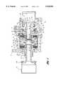
- FIG. 1is a cross-sectional view of a first embodiment of the invention wherein the limited slip differential has torque-sensitive features and speed-sensitive hydrostatic torque bias features;
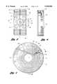
- FIG. 2is an end elevation view of the pressure rings and differential pinions in the embodiment of FIG. 1;
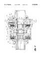
- FIG. 3is an enlarged view of the internal elements of the limited slip differential shown in FIG. 1;
- FIG. 4is a cross-sectional view taken along the plane of section line 4--4 of FIG. 3;
- FIG. 5is a side view as viewed in the direction of the axis of the differential assembly showing the ramp portions of one of the pressure rings of the assembly of FIG. 1;
- FIG. 6is a cross-sectional view taken along the plane of section line 6--6 of FIG. 5;
- FIG. 7is a cross-sectional view taken along the plane of section line 7--7 of FIG. 3;
- FIG. 8is a cross-sectional view taken along the plane of section line 8--8 of FIG. 4;
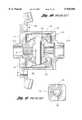
- FIG. 9is an overall cross-sectional assembly view of a second embodiment of the invention.
- FIG. 10is a cross-sectional view of a prior art torque-sensitive differential mechanism.
- FIG. 11is a cross-sectional view taken along the plane of section line 11--11 of the prior art differential mechanism of FIG. 10.
- FIG. 1shows a first embodiment of the invention wherein a torque-sensitive bias and a hydrostatic speed-sensitive bias are obtained without the presence of a piston that is actuated by the hydrostatic pressure developed by a hydrostatic pump.
- reference numeral 10designates a differential housing. It is rotatably journaled in the main housing 12 that forms a part of an axle assembly for the traction wheels of an automotive vehicle.
- Mounting flange 14is adapted to support the housing in a transmission assembly for a vehicle, the transmission assembly not being illustrated in FIG. 1.
- the housing 12acts as a differential carrier for planetary gearing illustrated generally at 16.
- the carrier housing 10has a support shaft 18, which serves as a torque input shaft.
- Shaft 18extends through a bearing opening formed in a forward wall 20 of the housing 10.
- a corresponding support shaft 22extends through a bearing opening formed in end plate 24, which is secured by threaded fasteners such as bolts 26 to the right end of the housing 12.
- the support shaft or torque input shaft 18is journaled in the bearing opening in the wall 20 by bearing 28.
- a corresponding bearing 30journals the support shaft 22 in the bearing opening in the end plate 24.
- a first torque output shaft 32is rotatably journaled in support shaft 22 by needle bearing 34. It is adapted to be connected to the inboard end of an axle half shaft by a universal joint (not shown) .
- the universal jointwould be located in a universal joint housing 36, which is journaled in the end wall 24 by bearing 38.
- a fluid seal 40isolates the interior of the housing.
- the opposite side of the differential assemblyincludes a second output shaft 42, which is journaled by a needle bearing 44 in support sleeve shaft 18 of the carrier housing 10.
- the outboard end of the shaft 42as in the case of the outboard end of the shaft 32, has a universal joint (not shown).
- the universal joint for shaft 42is located within the universal joint housing 46.
- differential side gear 48which has bevel teeth that drivably engage bevel teeth on differential pinion 50.
- Differential pinion 50also meshes with the bevel teeth of a second differential side gear 52, which is splined to the inboard end of the shaft 42.
- a first multiple disk clutchis located directly adjacent differential side gear 48, as shown at 54.
- the clutch disksare arranged in interdigital relationship. Alternate disks of the clutch pack shown at 54 are splined to carrier housing 10, as indicated at 56. The other disks of the disk pack 54 are splined as shown at 58 to differential side gear 48.
- a second multiple disk clutch pack 60is located directly adjacent side gear 52.
- clutch pack 60includes externally splined disks 64 which are connected drivably to the differential carrier housing 10. Alternately spaced disks of the disk pack 60 are internally splined, as shown at 66, to a clutch element that is secured and driven by differential side gear 52.
- a first pressure ring 68is situated adjacent the disk pack 54.
- a corresponding pressure ring 70is situated directly adjacent disk pack 60.
- Each pressure ringhas cam surfaces defined by ramps. Ramps 69 on pressure ring 68 are engaged by a radial extension 72 of the pinion 50. Similarly, cam surfaces defined by ramps are formed on pressure ring 70 as shown at 74. Ramps 74 are engaged by the extension 72 of the pinion 50.
- a second differential pinion 76also engages the differential side gears 48 and 52.
- Pinions 76 and 50are journaled on a pinion shaft, sometimes referred to as a "spider", as generally shown at 78.
- a pinion shaftsometimes referred to as a "spider"
- Either two, three or four pinionsmay be mounted on a common pinion shaft or spider, depending upon the capacity that is desired.
- FIG. 1for purposes of simplicity a pressure plate and ramp configuration for only one of the pinions, although a similar pressure plate and ramp configuration may be employed for any or all of the other pinions.
- the pressure plate 68has ramp surfaces 69 that are approximately oriented at 30 degrees relative to the vertical axis 80, as shown in FIG. 2.
- the housing 10acts on the pressure rings.
- the pressure ring rampsact on the pinions.
- the reactive torqueis in the direction of arrow 82, which causes spreading forces on the pressure rings.
- the differential mechanismis subjected to acceleration torque, as indicated by the directional arrow 83 in FIG. 2, the pinion 50 will exert an axial force on the pressure ring 68 which will energize the clutch disk pack 54.
- ramp 74which is also oriented at a angle of about 30 degrees, is engaged by the pinion 50, thereby creating an axial force that energized clutch disk pack 60.
- the ramp 86will be engaged by pinion 50, thereby applying an axial force on the pressure ring 70.
- pressure ring 68 and ramp 84The same is true for pressure ring 68 and ramp 84.
- the ramps 84 and 86are oriented at an angle that is substantially greater than the angle of ramps 69 and 74.
- the pressure ring 68is externally splined by splines 88 to the carrier housing 10.
- pressure ring 70is externally splined by splines 90 to the carrier housing 10. The pressure rings thus are held fast against angular motion relative to the carrier housing, but axial movement of the pressure rings relative to the carrier housing is permitted by the splines.
- the carrier housing 10has an end plate 92, which is secured to the open end of the differential carrier housing by suitable fasteners, such as threaded fasteners 94.
- a positive displacement Gerotor pump assembly 96is situated between the plate 92 and a plate 98 of the carrier housing 10. The fasteners 94 secure the plates 92 and 98 and the carrier housing 10 securely together.
- the pump assemblyis best seen in FIG. 7. It includes a fixed eccentric ring 100 and a first rotary pumping member 102 that is positioned eccentrically within the ring 100 relative to the axis of the differential assembly.
- An inner pump gear member 104 located within the pumping member 106is positioned concentrically with respect to the axis of the differential. It is formed with internal spline teeth, which establish a driving connection with axle half shaft 32.
- Pumping member 102is circular and has internal gear tooth spaces 106.
- Pumping member 104has external gear teeth 108 which register with the internal tooth spaces 106.
- the gear teeth 108are one fewer in number than the number of tooth spaces 106.
- the internal gear teeth and the external gear teeth of the Geroter pumpare formed with involute profiles in known manner.
- the plate 98is provided with inlet and outlet ports, seen in phantom in FIG. 4 at 110 and 112, respectively. These ports communicate with the fluid pumping chambers created by the meshing gear teeth of the pumping elements. As the pump gear 104 rotates, it drives the outer pumping member. The pumping chamber defined by the spaces between the internal and external teeth of the pumping members communicates with the outlet port during the phase of the pump rotation when the volume of the gear tooth spaces increases. Those spaces communicate with the inlet port shown at 112.
- a needle valve 114is positioned in a threaded opening in the plate 98. It includes a main body 116 which is threaded in a radial threaded opening in the plate 98. It includes also a stem 118 which registers with a flow restricting port 120 that communicates with the outlet port 110. The port 120 is in fluid communication with a cross-over passage 122, which in turn communicates with the inlet port 112. Fluid pumped by the pumping members then is transferred from the port 110 and through the flow restricting port 120 to the inlet side of the pump. This recirculation of the pumped fluid provides a hydrostatic resistance to the rotation of one pumping element relative to the other.
- the flow accommodated by the cross-over passage 122is bi-directional, the direction of flow depending on the direction of relative rotation of the pumping members 102 and 104.
- An O-ring seal 124 on the adjustable valve 114isolates the pressurized fluid within the closed fluid flow circuit.
- FIG. 8shows a cross-sectional view of the plate 98.
- the threaded radially-extending valve opening for the valve 114is indicated in FIG. 8 by reference numeral 126.
- a lubricant supply passageis shown in FIG. 1 at 128.
- a fluid fitting 130is received in the passage 128.
- Hydraulic fluid supply for the pumpis distributed to the inlet port of the pump. Communication with the inlet port is established by annular cavity 132, which in turn communicates with inlet port cavity 134 formed in the end plate 92.
- Flutter valves (check valves) 136provide one-way fluid communication between the cavity 132 and the port cavity 134. They provide communication between cavity 132 and port cavity 138 when relative rotation of the pumping members is in one direction when the relative rotation reverses. This ensures pumping operation regardless of rotational direction.
- Cavity 132communicates with the port 110, as best seen in FIG. 4.
- Port 110is in fluid communication with valve port 120 and with cross-over passage 122 extending to the port 112 and port cavity 138.
- the flutter valvesfunction in a manner similar to check valves 60 disclosed in U.S. Pat. No. 5,310,388.
- Torqueis distributed to the carrier housing 10 through torque input shaft 18, which is splined to a torque input ring gear.
- the output shaft 42which is journaled in the shaft 18, is supported by bearing 140, which in turn is supported by differential housing portions (not shown). Bearing 140 corresponds to bearing 38 for the shaft 32.
- the torque component of the differential biaswill diminish as one actual shaft overspeeds the other. Such overspeeding will cause the pumping members 102 and 104 to rotate with respect to each other. This creates a high hydrostatic pressure on the outlet side of the Gerotor pump, thereby absorbing energy and resisting the tendency of the shafts 42 or 32 to overspeed, one with respect to the other.
- the differentialthus is both speed-sensitive and torque-sensitive as a torque bias is established.
- the speed-sensitive component of the differential biascomplements the torque-sensitive bias because a decrease in torque-sensitive bias will be accompanied by an increase in speed-sensitive bias. It also provides a mechanical damping effect for the torque sensitive bias because of the hydrostatic action.
- a torque input ring gear 144delivers torque to a carrier housing 146, which encloses pressure plates 148 and 150.
- Pressure plates 148 and 150which are splined to housing 146, have cam surfaces as seen at 152 and 154 in FIG. 11. These cam surfaces engage pinion shaft 156.
- Pinions 158engage side gears 160 and 162.
- the design of FIGS. 10 and 11have friction disk clutch packs 164 and 166, which are engaged in response to axial pressure forces of the pressure rings 148 and 150.
- Each of the side gearsis internally splined to permit a driving connection with a torque output half shaft.
- the ramp angles ⁇ on both sides of the pinion shaftare about 45°.
- the torque bias on decelerationis approximately equal to the torque bias on acceleration for the prior art design illustrated in FIGS. 10 and 11.
- the angle of the rampscan be tailored to meet any particular design requirement. In the example of the embodiment of FIG. 1, as previously explained, the ramp angle on the acceleration side of the pinion 50 is about 30° and the ramp angle on the deceleration side is about 45°.
- the discharge side of the pumpis in fluid communication with a pressure chamber 170 formed in the plate 98'.
- the pressure chamberis in the form of an annular cylinder within which is situated annular piston 172.
- the chamber 170is in fluid communication with a high pressure passage corresponding to passage 122 of FIG. 4.
- the piston 172is situated directly adjacent friction disk clutch pack 54'.
- the clutch packis energized by the piston force created by the pressure in the annular chamber 170.
- the hydrostatic resistance offered by the pumping members of the gear pump 96'is complemented by the torque bias established by the clutch pack 54'.
- the total torque biasis the greater of the torque sensitive bias and the hydrostatic (speed sensitive) pressure bias, plus the pumping resistance.
- each of the elements that has a counterpart element in the embodiment of FIG. 1has been identified by similar reference numerals, although prime notations are added.
- the speed-sensitive biaswould be increased relative to the speed-sensitive bias that would be available for the embodiment of FIG. 1. If, for example, a car having a differential of the kind shown in FIG. 1 were to be in a turning maneuver from right to left and if, for some reason, the inner left wheel should leave the ground or encounter a low friction surface, a torque bias still will be maintained thereby preventing excessive spin-out of the inner left wheel. When the inner left wheel re-engages the road surface, the normal tendency for the vehicle to understeer is significantly reduced. Thus, the driver has greater control of the vehicle during such turning maneuvers.
- the hydrostatic fluid for the pumpis isolated from the fluid within the differential housing 12 or 12' by fluid seals. These are shown in FIG. 1 at 174 and 176. They are shown in FIG. 9 at 174' and 176'.
- the torque biascan be tuned by means of an orifice and an orifice valve in the piston as disclosed in U.S. Pat. No. 5,595,214. Further tuning can be effected using the threaded adjustment valve seen in FIG. 4 at 114.
- U.S. Pat. No. 5,595,214, as well as U.S. Pat. Nos. 5,536,215; 5,310,388; and 5,611,746are assigned to the assignee of the present invention and are incorporated herein by reference.
Landscapes
- Engineering & Computer Science (AREA)
- General Engineering & Computer Science (AREA)
- Mechanical Engineering (AREA)
- Physics & Mathematics (AREA)
- Fluid Mechanics (AREA)
- Retarders (AREA)
Abstract
Description
Claims (9)
Priority Applications (8)
| Application Number | Priority Date | Filing Date | Title |
|---|---|---|---|
| US09/114,505US5938556A (en) | 1998-07-13 | 1998-07-13 | Differential speed-sensitive and torque-sensitive limited slip coupling |
| BR9912420-3ABR9912420A (en) | 1998-07-13 | 1999-07-06 | Differential coupling with limited slip sensitive to speed and torque |
| EP99932257AEP1097319A1 (en) | 1998-07-13 | 1999-07-06 | Differential speed-sensitive and torque-sensitive limited slip coupling |
| AU48606/99AAU4860699A (en) | 1998-07-13 | 1999-07-06 | Differential speed-sensitive and torque-sensitive limited slip coupling |
| MXPA01000477AMXPA01000477A (en) | 1998-07-13 | 1999-07-06 | Differential speed-sensitive and torque-sensitive limited slip coupling. |
| PCT/US1999/015189WO2000003161A1 (en) | 1998-07-13 | 1999-07-06 | Differential speed-sensitive and torque-sensitive limited slip coupling |
| JP2000559361AJP4491764B2 (en) | 1998-07-13 | 1999-07-06 | Differential speed sensitive and torque sensitive limited slip coupling |
| CA002337400ACA2337400A1 (en) | 1998-07-13 | 1999-07-06 | Differential speed-sensitive and torque-sensitive limited slip coupling |
Applications Claiming Priority (1)
| Application Number | Priority Date | Filing Date | Title |
|---|---|---|---|
| US09/114,505US5938556A (en) | 1998-07-13 | 1998-07-13 | Differential speed-sensitive and torque-sensitive limited slip coupling |
Publications (1)
| Publication Number | Publication Date |
|---|---|
| US5938556Atrue US5938556A (en) | 1999-08-17 |
Family
ID=22355635
Family Applications (1)
| Application Number | Title | Priority Date | Filing Date |
|---|---|---|---|
| US09/114,505Expired - LifetimeUS5938556A (en) | 1998-07-13 | 1998-07-13 | Differential speed-sensitive and torque-sensitive limited slip coupling |
Country Status (8)
| Country | Link |
|---|---|
| US (1) | US5938556A (en) |
| EP (1) | EP1097319A1 (en) |
| JP (1) | JP4491764B2 (en) |
| AU (1) | AU4860699A (en) |
| BR (1) | BR9912420A (en) |
| CA (1) | CA2337400A1 (en) |
| MX (1) | MXPA01000477A (en) |
| WO (1) | WO2000003161A1 (en) |
Cited By (34)
| Publication number | Priority date | Publication date | Assignee | Title |
|---|---|---|---|---|
| US6155947A (en)* | 1999-05-26 | 2000-12-05 | Mclaren Automotive Group, Inc. | Speed-sensitive differential |
| US6168545B1 (en)* | 1999-05-26 | 2001-01-02 | Mclaren Automotive Group, Inc. | Limited slip differential with spring-loaded clutches |
| US6183387B1 (en)* | 1999-05-26 | 2001-02-06 | Dana Corporation | Variable pressure relief system for hydraulically actuated limited slip differentials |
| US6186258B1 (en)* | 1999-02-09 | 2001-02-13 | General Motors Corporation | Dynamic all wheel drive |
| US6315097B1 (en) | 2000-03-29 | 2001-11-13 | New Venture Gear, Inc. | Hydromechanical coupling with adaptive clutch control |
| US6440027B1 (en) | 1999-01-26 | 2002-08-27 | Steyr-Daimler-Puch Fahrzeugtechnik | Speed difference-dependent hydraulic coupling with temperature compensation |
| US6464056B1 (en) | 1999-08-06 | 2002-10-15 | Mclaren Automotive Group, Inc. | Electronically controlled hydraulic coupling |
| US6544137B2 (en) | 2001-07-18 | 2003-04-08 | Visteon Global Technologies, Inc. | Differential device |
| US6544136B2 (en) | 2001-07-18 | 2003-04-08 | Visteon Global Technologies, Inc. | Differential device |
| US6575281B2 (en) | 2001-07-18 | 2003-06-10 | Visteon Global Technologies, Inc. | Coupling device |
| US6578692B2 (en) | 2001-03-27 | 2003-06-17 | New Venture Gear, Inc. | Rear drive module for all-wheel drive vehicle |
| US6591714B2 (en) | 2001-07-18 | 2003-07-15 | Visteon Global Technologies, Inc. | Coupling device |
| US6676555B2 (en) | 2001-12-14 | 2004-01-13 | Visteon Global Technologies, Inc. | Cone friction clutch |
| US6681913B2 (en) | 2001-07-18 | 2004-01-27 | Visteon Global Technologies, Inc. | Coupling device |
| US20040024511A1 (en)* | 2000-10-11 | 2004-02-05 | Hyeongcheol Lee | Torque-biasing system |
| US6688446B2 (en) | 2001-03-27 | 2004-02-10 | New Venture Gear, Inc. | Rear drive module for all-wheel drive vehicle |
| US20040072647A1 (en)* | 2000-12-08 | 2004-04-15 | Christos Valasopoulos | Components system for engaging a standard differential |
| US20040149505A1 (en)* | 2001-04-02 | 2004-08-05 | Burns Timothy M. | Electronically-tuned hydromechanical coupling |
| US6859715B2 (en) | 2000-10-11 | 2005-02-22 | Visteon Global Technologies, Inc. | Torque-biasing system |
| WO2005078316A1 (en)* | 2004-02-11 | 2005-08-25 | Chang Sung Seok | Limited slip differential with friction using a pressure generating device |
| US20110301824A1 (en)* | 2010-06-03 | 2011-12-08 | Polaris Industries Inc. | Electronic throttle control |
| US20140288790A1 (en)* | 2011-10-17 | 2014-09-25 | Rainer Drexler | Multi-disc clutch lock having a differential housing |
| US9115785B1 (en)* | 2012-11-27 | 2015-08-25 | Radu Kramer | Compact drive mechanism with selective reverse power output |
| CN104948707A (en)* | 2015-06-30 | 2015-09-30 | 南平市建阳区汽车锻压件厂 | Differential anti-slip structure with vibration absorption structures |
| US9321451B2 (en)* | 2014-09-30 | 2016-04-26 | Ford Global Technologies, Llc | Managing ring gear torque in a hybrid electric vehicle to increase available wheel torque |
| CN108621681A (en)* | 2018-05-14 | 2018-10-09 | 冯萍 | A kind of automobile device for lowering persons based on hydraulic stem control |
| US20180319276A1 (en)* | 2017-05-04 | 2018-11-08 | Borgwarner Inc. | Tubeless lubrication delivery system for a compact transfer case |
| US11878678B2 (en) | 2016-11-18 | 2024-01-23 | Polaris Industries Inc. | Vehicle having adjustable suspension |
| US11904648B2 (en) | 2020-07-17 | 2024-02-20 | Polaris Industries Inc. | Adjustable suspensions and vehicle operation for off-road recreational vehicles |
| US11912096B2 (en) | 2017-06-09 | 2024-02-27 | Polaris Industries Inc. | Adjustable vehicle suspension system |
| US11919524B2 (en) | 2014-10-31 | 2024-03-05 | Polaris Industries Inc. | System and method for controlling a vehicle |
| US11970036B2 (en) | 2012-11-07 | 2024-04-30 | Polaris Industries Inc. | Vehicle having suspension with continuous damping control |
| US11975584B2 (en) | 2018-11-21 | 2024-05-07 | Polaris Industries Inc. | Vehicle having adjustable compression and rebound damping |
| US12397878B2 (en) | 2020-05-20 | 2025-08-26 | Polaris Industries Inc. | Systems and methods of adjustable suspensions for off-road recreational vehicles |
Citations (8)
| Publication number | Priority date | Publication date | Assignee | Title |
|---|---|---|---|---|
| US2949792A (en)* | 1959-11-09 | 1960-08-23 | Gen Motors Corp | Differential assembly |
| US3724289A (en)* | 1971-03-29 | 1973-04-03 | Caterpillar Tractor Co | Limited slip differential with clutch control means |
| US5059160A (en)* | 1988-11-02 | 1991-10-22 | Carraro S.P.A. | Self-locking differential gear |
| US5299986A (en)* | 1991-01-21 | 1994-04-05 | Carraro S.P.A. | Differential lock device |
| US5310388A (en)* | 1993-02-10 | 1994-05-10 | Asha Corporation | Vehicle drivetrain hydraulic coupling |
| US5536215A (en)* | 1993-02-10 | 1996-07-16 | Asha Corporation | Hydraulic coupling for vehicle drivetrain |
| US5595214A (en)* | 1993-02-10 | 1997-01-21 | Asha Corporation | Hydraulic coupling for vehicle drivetrain |
| US5611746A (en)* | 1995-06-28 | 1997-03-18 | Asha Corporation | Vehicle drivetrain coupling |
- 1998
- 1998-07-13USUS09/114,505patent/US5938556A/ennot_activeExpired - Lifetime
- 1999
- 1999-07-06AUAU48606/99Apatent/AU4860699A/ennot_activeAbandoned
- 1999-07-06MXMXPA01000477Apatent/MXPA01000477A/ennot_activeIP Right Cessation
- 1999-07-06JPJP2000559361Apatent/JP4491764B2/ennot_activeExpired - Fee Related
- 1999-07-06CACA002337400Apatent/CA2337400A1/ennot_activeAbandoned
- 1999-07-06WOPCT/US1999/015189patent/WO2000003161A1/ennot_activeApplication Discontinuation
- 1999-07-06EPEP99932257Apatent/EP1097319A1/ennot_activeWithdrawn
- 1999-07-06BRBR9912420-3Apatent/BR9912420A/ennot_activeApplication Discontinuation
Patent Citations (8)
| Publication number | Priority date | Publication date | Assignee | Title |
|---|---|---|---|---|
| US2949792A (en)* | 1959-11-09 | 1960-08-23 | Gen Motors Corp | Differential assembly |
| US3724289A (en)* | 1971-03-29 | 1973-04-03 | Caterpillar Tractor Co | Limited slip differential with clutch control means |
| US5059160A (en)* | 1988-11-02 | 1991-10-22 | Carraro S.P.A. | Self-locking differential gear |
| US5299986A (en)* | 1991-01-21 | 1994-04-05 | Carraro S.P.A. | Differential lock device |
| US5310388A (en)* | 1993-02-10 | 1994-05-10 | Asha Corporation | Vehicle drivetrain hydraulic coupling |
| US5536215A (en)* | 1993-02-10 | 1996-07-16 | Asha Corporation | Hydraulic coupling for vehicle drivetrain |
| US5595214A (en)* | 1993-02-10 | 1997-01-21 | Asha Corporation | Hydraulic coupling for vehicle drivetrain |
| US5611746A (en)* | 1995-06-28 | 1997-03-18 | Asha Corporation | Vehicle drivetrain coupling |
Cited By (51)
| Publication number | Priority date | Publication date | Assignee | Title |
|---|---|---|---|---|
| US6440027B1 (en) | 1999-01-26 | 2002-08-27 | Steyr-Daimler-Puch Fahrzeugtechnik | Speed difference-dependent hydraulic coupling with temperature compensation |
| US6186258B1 (en)* | 1999-02-09 | 2001-02-13 | General Motors Corporation | Dynamic all wheel drive |
| US6168545B1 (en)* | 1999-05-26 | 2001-01-02 | Mclaren Automotive Group, Inc. | Limited slip differential with spring-loaded clutches |
| US6183387B1 (en)* | 1999-05-26 | 2001-02-06 | Dana Corporation | Variable pressure relief system for hydraulically actuated limited slip differentials |
| US6155947A (en)* | 1999-05-26 | 2000-12-05 | Mclaren Automotive Group, Inc. | Speed-sensitive differential |
| US6464056B1 (en) | 1999-08-06 | 2002-10-15 | Mclaren Automotive Group, Inc. | Electronically controlled hydraulic coupling |
| US6315097B1 (en) | 2000-03-29 | 2001-11-13 | New Venture Gear, Inc. | Hydromechanical coupling with adaptive clutch control |
| US20040024511A1 (en)* | 2000-10-11 | 2004-02-05 | Hyeongcheol Lee | Torque-biasing system |
| US6882922B2 (en) | 2000-10-11 | 2005-04-19 | Visteon Global Technologies, Inc. | Torque-biasing system |
| US6859715B2 (en) | 2000-10-11 | 2005-02-22 | Visteon Global Technologies, Inc. | Torque-biasing system |
| US20040072647A1 (en)* | 2000-12-08 | 2004-04-15 | Christos Valasopoulos | Components system for engaging a standard differential |
| US6578692B2 (en) | 2001-03-27 | 2003-06-17 | New Venture Gear, Inc. | Rear drive module for all-wheel drive vehicle |
| US6688446B2 (en) | 2001-03-27 | 2004-02-10 | New Venture Gear, Inc. | Rear drive module for all-wheel drive vehicle |
| US6953411B2 (en) | 2001-04-02 | 2005-10-11 | Magna Drivetrain Of America, Inc. | Electronically-tuned hydromechanical coupling |
| US20040149505A1 (en)* | 2001-04-02 | 2004-08-05 | Burns Timothy M. | Electronically-tuned hydromechanical coupling |
| US6681913B2 (en) | 2001-07-18 | 2004-01-27 | Visteon Global Technologies, Inc. | Coupling device |
| US6591714B2 (en) | 2001-07-18 | 2003-07-15 | Visteon Global Technologies, Inc. | Coupling device |
| US6575281B2 (en) | 2001-07-18 | 2003-06-10 | Visteon Global Technologies, Inc. | Coupling device |
| US6544136B2 (en) | 2001-07-18 | 2003-04-08 | Visteon Global Technologies, Inc. | Differential device |
| US6544137B2 (en) | 2001-07-18 | 2003-04-08 | Visteon Global Technologies, Inc. | Differential device |
| US6676555B2 (en) | 2001-12-14 | 2004-01-13 | Visteon Global Technologies, Inc. | Cone friction clutch |
| CN100540950C (en)* | 2004-02-11 | 2009-09-16 | 成均馆大学校产学协力团 | Friction limited slip differential using pressure generating device |
| US7559869B2 (en) | 2004-02-11 | 2009-07-14 | Sungkyunkwan University Foundation For Corporate Collaboration | Limited slip differential with friction using a pressure generating device |
| WO2005078316A1 (en)* | 2004-02-11 | 2005-08-25 | Chang Sung Seok | Limited slip differential with friction using a pressure generating device |
| US20070161452A1 (en)* | 2004-02-11 | 2007-07-12 | Seok Chang S | Limited slip differential with friction using a pressure generating device |
| US10086698B2 (en) | 2010-06-03 | 2018-10-02 | Polaris Industries Inc. | Electronic throttle control |
| US20110301824A1 (en)* | 2010-06-03 | 2011-12-08 | Polaris Industries Inc. | Electronic throttle control |
| US10933744B2 (en) | 2010-06-03 | 2021-03-02 | Polaris Industries Inc. | Electronic throttle control |
| US9162573B2 (en) | 2010-06-03 | 2015-10-20 | Polaris Industries Inc. | Electronic throttle control |
| US9381810B2 (en)* | 2010-06-03 | 2016-07-05 | Polaris Industries Inc. | Electronic throttle control |
| US20140288790A1 (en)* | 2011-10-17 | 2014-09-25 | Rainer Drexler | Multi-disc clutch lock having a differential housing |
| EP2769123B1 (en)* | 2011-10-17 | 2020-09-09 | Drexler, Rainer | Multi-disc clutch lock having a differential housing |
| US9382991B2 (en)* | 2011-10-17 | 2016-07-05 | Rainer Drexler | Multi-disc clutch lock having a differential housing |
| US11970036B2 (en) | 2012-11-07 | 2024-04-30 | Polaris Industries Inc. | Vehicle having suspension with continuous damping control |
| US12291069B2 (en) | 2012-11-07 | 2025-05-06 | Polaris Industries Inc. | Vehicle having suspension with continuous damping control |
| US9115785B1 (en)* | 2012-11-27 | 2015-08-25 | Radu Kramer | Compact drive mechanism with selective reverse power output |
| US9321451B2 (en)* | 2014-09-30 | 2016-04-26 | Ford Global Technologies, Llc | Managing ring gear torque in a hybrid electric vehicle to increase available wheel torque |
| US12325432B2 (en) | 2014-10-31 | 2025-06-10 | Polaris Industries Inc. | System and method for controlling a vehicle |
| US11919524B2 (en) | 2014-10-31 | 2024-03-05 | Polaris Industries Inc. | System and method for controlling a vehicle |
| CN104948707A (en)* | 2015-06-30 | 2015-09-30 | 南平市建阳区汽车锻压件厂 | Differential anti-slip structure with vibration absorption structures |
| US11878678B2 (en) | 2016-11-18 | 2024-01-23 | Polaris Industries Inc. | Vehicle having adjustable suspension |
| US12337824B2 (en) | 2016-11-18 | 2025-06-24 | Polaris Industries Inc. | Vehicle having adjustable suspension |
| US20180319276A1 (en)* | 2017-05-04 | 2018-11-08 | Borgwarner Inc. | Tubeless lubrication delivery system for a compact transfer case |
| US10583734B2 (en)* | 2017-05-04 | 2020-03-10 | Borgwarner Inc. | Tubeless lubrication delivery system for a compact transfer case |
| US12330467B2 (en) | 2017-06-09 | 2025-06-17 | Polaris Industries Inc. | Adjustable vehicle suspension system |
| US11912096B2 (en) | 2017-06-09 | 2024-02-27 | Polaris Industries Inc. | Adjustable vehicle suspension system |
| CN108621681A (en)* | 2018-05-14 | 2018-10-09 | 冯萍 | A kind of automobile device for lowering persons based on hydraulic stem control |
| US11975584B2 (en) | 2018-11-21 | 2024-05-07 | Polaris Industries Inc. | Vehicle having adjustable compression and rebound damping |
| US12384214B2 (en) | 2018-11-21 | 2025-08-12 | Polaris Industries Inc. | Vehicle having adjustable compression and rebound damping |
| US12397878B2 (en) | 2020-05-20 | 2025-08-26 | Polaris Industries Inc. | Systems and methods of adjustable suspensions for off-road recreational vehicles |
| US11904648B2 (en) | 2020-07-17 | 2024-02-20 | Polaris Industries Inc. | Adjustable suspensions and vehicle operation for off-road recreational vehicles |
Also Published As
| Publication number | Publication date |
|---|---|
| BR9912420A (en) | 2001-06-05 |
| CA2337400A1 (en) | 2000-01-20 |
| JP2002520551A (en) | 2002-07-09 |
| EP1097319A1 (en) | 2001-05-09 |
| JP4491764B2 (en) | 2010-06-30 |
| AU4860699A (en) | 2000-02-01 |
| MXPA01000477A (en) | 2003-10-15 |
| WO2000003161A1 (en) | 2000-01-20 |
Similar Documents
| Publication | Publication Date | Title |
|---|---|---|
| US5938556A (en) | Differential speed-sensitive and torque-sensitive limited slip coupling | |
| US5655983A (en) | Hydromechanical system for limiting differential speed between differentially rotating members | |
| US7547265B2 (en) | Variable biasing differential | |
| US6814681B2 (en) | On-demand all-wheel drive system | |
| US6161643A (en) | System of controlling torque transfer in a motor vehicle and related method | |
| US6953411B2 (en) | Electronically-tuned hydromechanical coupling | |
| JP2007085551A6 (en) | Transfer case for four-wheel drive vehicles | |
| US6513615B2 (en) | Full-time all-wheel drive power take-off unit for motor vehicle | |
| US6168545B1 (en) | Limited slip differential with spring-loaded clutches | |
| EP1104714B1 (en) | Power transmission device for a four-wheel drive vehicle | |
| US4916973A (en) | Torque biased differential mechanism | |
| KR890001336B1 (en) | Differential with differential motion limiting mechanism | |
| JP2686082B2 (en) | Power transmission device | |
| US3442154A (en) | High traction differential gear unit for wheeled vehicles | |
| JPH07233863A (en) | Differential gear device | |
| EP1956260B1 (en) | A hydraulically operable coupling | |
| JP2779939B2 (en) | Vane clutch | |
| JP3300393B2 (en) | Driving force transmission device for four-wheel drive vehicles | |
| JPS6136537A (en) | Differential-movement restricting apparatus | |
| JPH06239154A (en) | Differential limiting type differential gear | |
| JPH0337427A (en) | Controlled differential rotation sensitive joint | |
| JPH0672631B2 (en) | Fluid fitting | |
| JPS61108014A (en) | 4-wheel drive drive coupling device |
Legal Events
| Date | Code | Title | Description |
|---|---|---|---|
| AS | Assignment | Owner name:ASHA CORPORATION, CALIFORNIA Free format text:ASSIGNMENT OF ASSIGNORS INTEREST;ASSIGNOR:LOWELL, JEFFREY;REEL/FRAME:009465/0371 Effective date:19980820 | |
| STCF | Information on status: patent grant | Free format text:PATENTED CASE | |
| AS | Assignment | Owner name:EATON CORPORATION, OHIO Free format text:ASSIGNMENT OF ASSIGNORS INTEREST;ASSIGNOR:MCLAREN PERFORMANCE TECHNOLOGY, INC.;REEL/FRAME:013484/0160 Effective date:20020723 | |
| FEPP | Fee payment procedure | Free format text:PAT HOLDER NO LONGER CLAIMS SMALL ENTITY STATUS, ENTITY STATUS SET TO UNDISCOUNTED (ORIGINAL EVENT CODE: STOL); ENTITY STATUS OF PATENT OWNER: LARGE ENTITY | |
| REFU | Refund | Free format text:REFUND - SURCHARGE, PETITION TO ACCEPT PYMT AFTER EXP, UNINTENTIONAL (ORIGINAL EVENT CODE: R2551); ENTITY STATUS OF PATENT OWNER: LARGE ENTITY | |
| FPAY | Fee payment | Year of fee payment:4 | |
| FEPP | Fee payment procedure | Free format text:ENTITY STATUS SET TO UNDISCOUNTED (ORIGINAL EVENT CODE: BIG.); ENTITY STATUS OF PATENT OWNER: LARGE ENTITY | |
| FPAY | Fee payment | Year of fee payment:8 | |
| FPAY | Fee payment | Year of fee payment:12 |