US5938389A - Metal can and method of making - Google Patents
Metal can and method of makingDownload PDFInfo
- Publication number
- US5938389A US5938389AUS08/900,564US90056497AUS5938389AUS 5938389 AUS5938389 AUS 5938389AUS 90056497 AUS90056497 AUS 90056497AUS 5938389 AUS5938389 AUS 5938389A
- Authority
- US
- United States
- Prior art keywords
- sidewall portion
- ribs
- strength
- sidewall
- metal
- Prior art date
- Legal status (The legal status is an assumption and is not a legal conclusion. Google has not performed a legal analysis and makes no representation as to the accuracy of the status listed.)
- Expired - Fee Related
Links
Images


Classifications
- B—PERFORMING OPERATIONS; TRANSPORTING
- B21—MECHANICAL METAL-WORKING WITHOUT ESSENTIALLY REMOVING MATERIAL; PUNCHING METAL
- B21D—WORKING OR PROCESSING OF SHEET METAL OR METAL TUBES, RODS OR PROFILES WITHOUT ESSENTIALLY REMOVING MATERIAL; PUNCHING METAL
- B21D51/00—Making hollow objects
- B21D51/16—Making hollow objects characterised by the use of the objects
- B21D51/26—Making hollow objects characterised by the use of the objects cans or tins; Closing same in a permanent manner
- B—PERFORMING OPERATIONS; TRANSPORTING
- B65—CONVEYING; PACKING; STORING; HANDLING THIN OR FILAMENTARY MATERIAL
- B65D—CONTAINERS FOR STORAGE OR TRANSPORT OF ARTICLES OR MATERIALS, e.g. BAGS, BARRELS, BOTTLES, BOXES, CANS, CARTONS, CRATES, DRUMS, JARS, TANKS, HOPPERS, FORWARDING CONTAINERS; ACCESSORIES, CLOSURES, OR FITTINGS THEREFOR; PACKAGING ELEMENTS; PACKAGES
- B65D1/00—Rigid or semi-rigid containers having bodies formed in one piece, e.g. by casting metallic material, by moulding plastics, by blowing vitreous material, by throwing ceramic material, by moulding pulped fibrous material or by deep-drawing operations performed on sheet material
- B65D1/12—Cans, casks, barrels, or drums
- B65D1/14—Cans, casks, barrels, or drums characterised by shape
- B65D1/16—Cans, casks, barrels, or drums characterised by shape of curved cross-section, e.g. cylindrical
- B65D1/165—Cylindrical cans
- B—PERFORMING OPERATIONS; TRANSPORTING
- B21—MECHANICAL METAL-WORKING WITHOUT ESSENTIALLY REMOVING MATERIAL; PUNCHING METAL
- B21D—WORKING OR PROCESSING OF SHEET METAL OR METAL TUBES, RODS OR PROFILES WITHOUT ESSENTIALLY REMOVING MATERIAL; PUNCHING METAL
- B21D22/00—Shaping without cutting, by stamping, spinning, or deep-drawing
- B21D22/20—Deep-drawing
- B21D22/28—Deep-drawing of cylindrical articles using consecutive dies
- B—PERFORMING OPERATIONS; TRANSPORTING
- B21—MECHANICAL METAL-WORKING WITHOUT ESSENTIALLY REMOVING MATERIAL; PUNCHING METAL
- B21D—WORKING OR PROCESSING OF SHEET METAL OR METAL TUBES, RODS OR PROFILES WITHOUT ESSENTIALLY REMOVING MATERIAL; PUNCHING METAL
- B21D51/00—Making hollow objects
- B21D51/16—Making hollow objects characterised by the use of the objects
- B21D51/26—Making hollow objects characterised by the use of the objects cans or tins; Closing same in a permanent manner
- B21D51/2646—Of particular non cylindrical shape, e.g. conical, rectangular, polygonal, bulged
- B—PERFORMING OPERATIONS; TRANSPORTING
- B65—CONVEYING; PACKING; STORING; HANDLING THIN OR FILAMENTARY MATERIAL
- B65D—CONTAINERS FOR STORAGE OR TRANSPORT OF ARTICLES OR MATERIALS, e.g. BAGS, BARRELS, BOTTLES, BOXES, CANS, CARTONS, CRATES, DRUMS, JARS, TANKS, HOPPERS, FORWARDING CONTAINERS; ACCESSORIES, CLOSURES, OR FITTINGS THEREFOR; PACKAGING ELEMENTS; PACKAGES
- B65D1/00—Rigid or semi-rigid containers having bodies formed in one piece, e.g. by casting metallic material, by moulding plastics, by blowing vitreous material, by throwing ceramic material, by moulding pulped fibrous material or by deep-drawing operations performed on sheet material
- B65D1/40—Details of walls
- B65D1/42—Reinforcing or strengthening parts or members
- B65D1/44—Corrugations
Definitions
- This inventionrelates to metal cans, such as those which are in wide use for packaging soft drinks and other beverages. More specifically, this invention relates to an improved metal can, and especially a stylized, shaped can, that provides enhanced strength characteristics at a given container weight as compared with conventional metal containers.
- German published patent application DE 23 08 420 (1974)discloses formation of a can body with either helical and longitudinal ribs by means of a standard drawing and ironing technique wherein the punch is configured to create the additional thickness of the reinforcing ribs.
- a similar inventionwas the subject of published PCT application WO83/01916.
- U.S. Pat. No. 3,610,018 to Swanson et al.discloses manufacturing circumferential reinforcement ribs into a steel can body in order to increase the buckling resistance of a steel can.
- a shaped canis typically made from a cylindrical metallic preform, which is shaped and sized quite similarly to a standard straight or cylindrical can body.
- the metallic preformis forced into the desired shape by one of a number of different known methods, most of which use mechanical or gaseous pressure, or some combination thereof.
- any deviation from a cylindrical shapecan reduce, among other things, the axial strength of the can.
- shaped canstend to be more susceptible than straight cans to outward bowing or other deformation such as when they are internally pressurized by carbonation. The extent, location and type of deformation will depend on the specific configuration of shaped can. For example, one shaped can design with which the inventors are familiar has a portion that includes broad, inwardly extending generally longitudinal depressions or grooves which tend to be pushed outwardly under pressure. The conventional thought would be that this could and must be rectified by increasing the can's wall thickness. Doing that, however, would add to the customer's projected packaging expenses, making the can design less attractive to the final customer, who is usually the soft drink manufacturer or bottler.
- a method of making a metal canincludes, according to one aspect of the invention steps of (a) forming a sidewall portion that has a plurality of circumferentially extending ribs integrated therein, the ribs providing additional hoop strength to the sidewall portion, and a plurality of substantially longitudinally extending ribs, the longitudinal and circumferential ribs thereby forming a gridwork of reinforcing cells in the sidewall portion; and (b) assembling at least one can end member to the sidewall portion to complete formation of a metal can.
- a method of making a non-cylindrical shaped metal can body that is provided with a stylized, irregular shapeincludes steps of (a) forming a substantially cylindrical sidewall portion that at least one circumferentially extending rib integrated therein, the rib providing additional strength to the sidewall portion; and (b) shaping the cylindrical sidewall portion into a non-cylindrical, stylized shape, and wherein the ribs are positioned at portions of the shaped sidewall portion that are anticipated to need increased hoop strength in order to withstand deformation under pressure, whereby the shaped sidewall portion is reinforced against deformation without increasing overall thickness of the sidewall.
- a metalcan includes a sidewall portion that has a plurality of circumferentially extending ribs and a plurality of substantially longitudinally extending ribs in the sidewall, the longitudinal and circumferential ribs forming a gridwork of reinforcing cells in the sidewall portion that will enhance the strength of the sidewall portion; and at least one can end member sealed to the sidewall portion, whereby the can has superior strength characteristics when compared to a can of like weight that does not possess such circumferentially extending ribs.
- a metal can bodyin a further aspect of the invention, includes a sidewall portion that has at least one circumferentially extending rib integrated therein, the rib providing additional hoop strength to the sidewall portion, and wherein the sidewall portion is configured in a non-cylindrical, stylized shape, and wherein the rib is positioned at a portion of the shaped sidewall portion that is anticipated to need increased hoop strength to withstand deformation under pressure.
- a metalcan includes a sidewall portion that has at least one circumferentially extending rib integrated therein, the rib providing additional hoop strength to the sidewall portion, and wherein the sidewall portion is configured in a non-cylindrical, stylized shape, and wherein the rib is positioned at a portion of the shaped sidewall portion that is anticipated to need increased hoop strength to withstand deformation under pressure; and at least one can end member sealed to the shaped sidewall portion, whereby a metal can is formed that is less likely to deform under the pressure of carbonation than a can without such reinforcing ribs.
- FIGS. 1 and 1Aare a diagrammatical view of a method of manufacturing a side wall for a can body or a shaped can preform according to a first embodiment of the invention
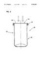
- FIG. 2is a cross sectional view taken through a reinforced can that is made according to the process depicted in FIG. 1;
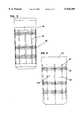
- FIG. 3is a side elevational view of a drawing and ironing punch that is made for use in a process according to a second embodiment of the invention
- FIG. 4depicts a can body or preform that is made according to the process using the drawing and ironing punch shown in FIG. 3;
- FIG. 5depicts a shaped metal can body that is made according to a preferred embodiment of the invention.
- a can body or preform 10 for a shaped canis depicted having a sidewall 12 along with a standard assembly 14 for drawing and ironing a can body, the details of which are well known in this area of technology.
- Assembly 14includes a punch body 16 and one or more rings 18, as, again, is well known in the industry.
- Can body or preform 10is preferably, although not necessarily, fabricated from aluminum.
- the can body preformis manufactured with at least one reinforced area 20, which is in the illustrated embodiment a pair of circumferentially extending ribs in the sidewall 12 of the can body or preform.
- the outer surface 24 of punch body 16includes a pair of circumferentially extending grooves 22 which allow formation of the correspondingly shaped ribs 26 during the drawing and ironing process.
- Ribs 26impart additional strength to the sidewall of can body/preform 12, which improves the vertical crush strength, the lateral crush strength, and the strength against expansion due to internal pressurization.
- a reinforced can 28may be manufactured from the sidewall of the can body/preform 12 by fastening a can end member 30 having an end panel 32 to the can body through a traditional double seam type joint.
- the process for joining the can end member 30 to the can bodyis well known in the industry.
- the punch and the drawing and ironing assembly 14 that is shown in FIG. 1may alternatively be embodied as a punch 36, shown in FIG. 3, that has, in addition to the circumferentially grooves 22, of which there are three in the embodiment of FIG. 3, a plurality of longitudinal grooves 38.
- a can body/preform 40 that is manufactured by use of the punch 36is illustrated in FIG. 4.
- can body/preform 40includes a corresponding number of circumferentially reinforcing ribs 26, and longitudinal reinforcing ribs 42.
- Ribs 42, 26interact to form a plurality of reinforcing cells 44, the combined effect of which substantially strengthen the rigidity of the sidewall of the can body/preform 40 to an extent that the strength to weight ratio of the can body/preform 40 exceeds that which was possible with a similarly shaped and weighted cylindrical can body configuration.
- This construction of the sidewall having the reinforcing cells 44in addition to increasing the strength to weight ratio, also increases the puncture resistance of the can wall body, thereby permitting additional lightweighting that would otherwise not be possible for fear of susceptibility to puncturing.
- a shaped metal can body 46is depicted which will be recognized as a design that is proprietary to a major soft drink manufacturer.
- This particular shaped can designincludes a number of inwardly extending longitudinal oriented grooves 62, which, absent reinforcement, tend to bow outwardly under pressure, thus making the design substantially unworkable unless the wall thickness of the can body is increased to an extent that would make the can body economically unattractive to the potential customer.
- this areais adequately reinforced without substantially increasing the weight of the can body. This is achieved by strategically placing reinforced areas 48, 50, 52 at portions of the shaped sidewall that are anticipated to need increased hoop strength in order not to deform under pressure.
- Reinforced areas 48, 50, 52are, in fact, the areas which correspond to the circumferential ribs 26 that are formed according to either the embodiment of the invention that is depicted in FIG. 1 or that which is depicted in FIG. 4. Rib 26 translate, after expansion of the can body into the shaped metal can body 46, into ribs 54, 56, 58, respectively.
- the longitudinal reinforcing ribs 42 that are illustrated in the embodiment 40may also be used to reinforce the shaped metal 46, and appear as longitudinal ribs 62 that are shaped and placed strategically at areas of potential weakness of the can body 46.
- the circumferential ribs 54, 56, 58 and the longitudinal ribs 60together define a number of reinforcement cells 64, which, as in the case of the preform/can body 40 in the embodiment of FIG. 4, substantially increase the strength of the shaped metal can body 46.
- the shaped metal can body 46may be assembly into a reinforce can in a method that identical to that depicted in FIG. 2.
- the inwardly protruding ribs described aboveadd strength, it is now possible to reduce the amount of metal in the sidewall.
- the inwardly protruding ribswill preferably rise above thin areas of the sidewall that are substantially wider than the ribs themselves.
- ribsmay be selectively placed to enhance the strength of the can in the areas of greatest stress.
- the thickness of the reinforcing ribs that are necessary to achieve the benefits described hereinabovewill depend on the specific shape and application of the can body itself, as well as the can's wall thickness. As an example, however, for a can having the shape shown in FIG. 5, it is preferable to have a baseline wall thickness of about 0.0041 inches, and for the vertical and circumferential reinforcing ribs to add about another 0.001 to 0.002 inches of wall thickness at the locations that are intended to be reinforced. This results in a total sidewall thickness of about 0.005 to 0.006 inches at the location of the reinforcing ribs.
Landscapes
- Engineering & Computer Science (AREA)
- Mechanical Engineering (AREA)
- Ceramic Engineering (AREA)
- Rigid Containers With Two Or More Constituent Elements (AREA)
- Containers Having Bodies Formed In One Piece (AREA)
- Forms Removed On Construction Sites Or Auxiliary Members Thereof (AREA)
- Injection Moulding Of Plastics Or The Like (AREA)
- Powder Metallurgy (AREA)
Abstract
Description
Claims (19)
Priority Applications (1)
| Application Number | Priority Date | Filing Date | Title |
|---|---|---|---|
| US08/900,564US5938389A (en) | 1996-08-02 | 1997-07-25 | Metal can and method of making |
Applications Claiming Priority (2)
| Application Number | Priority Date | Filing Date | Title |
|---|---|---|---|
| US2303996P | 1996-08-02 | 1996-08-02 | |
| US08/900,564US5938389A (en) | 1996-08-02 | 1997-07-25 | Metal can and method of making |
Publications (1)
| Publication Number | Publication Date |
|---|---|
| US5938389Atrue US5938389A (en) | 1999-08-17 |
Family
ID=21812770
Family Applications (1)
| Application Number | Title | Priority Date | Filing Date |
|---|---|---|---|
| US08/900,564Expired - Fee RelatedUS5938389A (en) | 1996-08-02 | 1997-07-25 | Metal can and method of making |
Country Status (14)
| Country | Link |
|---|---|
| US (1) | US5938389A (en) |
| EP (1) | EP0928229B1 (en) |
| KR (1) | KR20000029758A (en) |
| CN (1) | CN1227514A (en) |
| AR (1) | AR008277A1 (en) |
| AU (1) | AU721226B2 (en) |
| BR (1) | BR9710789A (en) |
| CO (1) | CO4770866A1 (en) |
| DE (1) | DE69706429T2 (en) |
| ID (1) | ID17112A (en) |
| PL (1) | PL331415A1 (en) |
| TR (1) | TR199900207T2 (en) |
| WO (1) | WO1998005445A1 (en) |
| ZA (1) | ZA976711B (en) |
Cited By (33)
| Publication number | Priority date | Publication date | Assignee | Title |
|---|---|---|---|---|
| USD435454S (en)* | 1999-01-14 | 2000-12-26 | Heineken Brouwerijen, B.V. | Beverage can |
| WO2001096209A1 (en)* | 2000-06-16 | 2001-12-20 | Corus Staal Bv | Metal can being a pressure tight metal packaging |
| USD455961S1 (en) | 2000-02-28 | 2002-04-23 | Coors Brewing Company | Beverage can |
| US6374657B1 (en) | 2000-10-30 | 2002-04-23 | Crown Cork & Seal Technologies Corporation | Method of making bump-up can bottom |
| USD490317S1 (en) | 2003-05-27 | 2004-05-25 | Chin-Tien Chang | Beverage can |
| USD512315S1 (en)* | 2004-07-08 | 2005-12-06 | Glud & Marstrand A/S | Beverage can |
| USD514937S1 (en)* | 2004-02-20 | 2006-02-14 | Chin-Tien Chang | Beverage can |
| USD524160S1 (en)* | 2005-03-02 | 2006-07-04 | Daiwa Can Company | Can |
| USD537736S1 (en) | 2005-12-29 | 2007-03-06 | Crown Packaging Technology, Inc. | Can |
| US20070241029A1 (en)* | 2004-06-01 | 2007-10-18 | Kosmyna Michael J | Antistatic paint cup |
| USD555514S1 (en) | 2006-01-06 | 2007-11-20 | Crown Packaging Technology, Inc. | Metal can |
| US20070266758A1 (en)* | 2006-05-16 | 2007-11-22 | Myers Gary L | Manufacturing Process to Produce a Necked Container |
| US20070295051A1 (en)* | 2006-06-26 | 2007-12-27 | Myers Gary L | Expanding die and method of shaping containers |
| US20080217823A1 (en)* | 2007-03-07 | 2008-09-11 | Ball Corporation | Mold construction for a process and apparatus for manufacturing shaped containers |
| USD584615S1 (en) | 2006-08-10 | 2009-01-13 | Thomas Henley Maxwell-Wood | Aerosol dispenser |
| US7665672B2 (en) | 2004-01-16 | 2010-02-23 | Illinois Tool Works Inc. | Antistatic paint cup |
| US7744011B2 (en) | 2004-01-16 | 2010-06-29 | Illinois Tool Works Inc. | Antistatic paint cup |
| US7757972B2 (en) | 2004-06-03 | 2010-07-20 | Illinois Tool Works Inc. | Conversion adapter for a fluid supply assembly |
| WO2010091965A1 (en) | 2009-02-13 | 2010-08-19 | Alfred Kärcher Gmbh & Co. Kg | Motor pump unit |
| US7874323B2 (en) | 2004-06-10 | 2011-01-25 | Illinois Tool Works, Inc. | Fluid supply assembly |
| WO2011027801A1 (en)* | 2009-09-07 | 2011-03-10 | Suntory Holdings Limited | Grooved metal can body and metal can |
| US8147216B2 (en) | 2007-02-21 | 2012-04-03 | Alfred Kaercher Gmbh & Co., Kg | Motor-pump unit |
| US8196770B2 (en) | 2004-01-16 | 2012-06-12 | Illinois Tool Works Inc. | Fluid supply assembly |
| US8341995B2 (en) | 2010-04-16 | 2013-01-01 | Alfons Haar, Inc. | Method for making can bodies having axial ribs and step shoulder bottoms |
| US20130306659A1 (en)* | 2012-05-15 | 2013-11-21 | Silgan Containers Llc | Strengthened food container and method |
| US8727748B2 (en) | 2008-11-14 | 2014-05-20 | Alfred Kaercher Gmbh & Co. Kg | High-pressure cleaning device |
| US8734129B2 (en) | 2009-02-13 | 2014-05-27 | Alfred Kaercher Gmbh & Co. Kg | Motor pump unit |
| US8920138B2 (en) | 2009-02-13 | 2014-12-30 | Alfred Kaercher Gmbh & Co. Kg | Motor pump unit |
| US8978922B2 (en) | 2012-05-15 | 2015-03-17 | Silgan Containers Llc | Strengthened food container and method |
| US9327338B2 (en) | 2012-12-20 | 2016-05-03 | Alcoa Inc. | Knockout for use while necking a metal container, die system for necking a metal container and method of necking a metal container |
| US9707615B2 (en) | 2010-08-20 | 2017-07-18 | Alcoa Usa Corp. | Shaped metal container and method for making same |
| USD864761S1 (en)* | 2012-12-21 | 2019-10-29 | Silgan Containers Llc | Container |
| US20230286006A1 (en)* | 2022-03-09 | 2023-09-14 | Ningbo Xinchen Intelligent Appliance Co., Ltd. | Spray gun |
Families Citing this family (7)
| Publication number | Priority date | Publication date | Assignee | Title |
|---|---|---|---|---|
| BR0003728B1 (en)* | 2000-06-20 | 2009-08-11 | manufacturing process of polygonal section tin and polygonal section tin. | |
| US7555927B2 (en)* | 2004-10-20 | 2009-07-07 | Universal Can Corporation | Bottle-shaped can manufacturing method and bottle-shaped can |
| EP2067543A1 (en)* | 2007-12-06 | 2009-06-10 | Crown Packaging Technology, Inc | Bodymaker |
| CN101695788B (en)* | 2009-10-30 | 2011-08-10 | 天津振汉机械装备有限公司 | Process for assembling and spot welding of circular seams of tank body of container |
| CN102745382A (en)* | 2012-06-26 | 2012-10-24 | 昇兴集团股份有限公司 | Metal tank |
| CN106224543A (en)* | 2016-09-30 | 2016-12-14 | 中车齐齐哈尔车辆有限公司 | A kind of tank container and tank body thereof |
| CN111770885B (en)* | 2017-12-28 | 2022-07-22 | 大和制罐株式会社 | Can body for aerosol having concave-convex processing portion in main body and method for producing the same |
Citations (73)
| Publication number | Priority date | Publication date | Assignee | Title |
|---|---|---|---|---|
| US840091A (en)* | 1905-02-28 | 1907-01-01 | Eberhard Schumacher | Means for making hollow metal articles. |
| GB216704A (en)* | 1923-06-19 | 1924-06-05 | Pietro Gessi | Improvements in apparatus for expanding deformed fire-boxes or fire-tubes of steam boilers |
| US2083943A (en)* | 1935-03-19 | 1937-06-15 | Clifford Mfg Co | Method of producing bellows units |
| DE830773C (en)* | 1950-03-04 | 1952-02-07 | Bernhard Kieruy | Tube for pasty substances |
| US2748464A (en)* | 1949-09-01 | 1956-06-05 | American Radiator & Standard | Method of cold forming steel pressure cylinders |
| DE1031257B (en)* | 1953-09-03 | 1958-06-04 | Perrot Regnerbau G M B H | Device for the production of socket pipes from smooth, thin-walled, welded sheet metal pipes |
| US2980993A (en)* | 1956-08-10 | 1961-04-25 | Lyon George Albert | Method of and apparatus for forming flanged casing bottom |
| US3029667A (en)* | 1955-08-31 | 1962-04-17 | Lodge & Shipley Co | Metal working |
| US3040684A (en)* | 1955-07-18 | 1962-06-26 | Hillgren Mfg Co | Apparatus for drawing door knobs |
| CH388887A (en)* | 1962-02-28 | 1965-03-15 | Gerzat Metallurg | Process for shaping a one-piece convex hollow body, device for implementing this process, and one-piece hollow body obtained according to this process |
| US3224239A (en)* | 1962-08-17 | 1965-12-21 | Continental Can Co | Pneumatic reshaping of cans |
| US3335590A (en)* | 1964-08-07 | 1967-08-15 | Boeing Co | Accurate control system for axial load bulge forming |
| US3461699A (en)* | 1967-05-23 | 1969-08-19 | Continental Can Co | Method and apparatus for reforming containers |
| DE1925014A1 (en)* | 1969-05-16 | 1970-11-19 | Eisner Dipl Ing Joachim H | Corrosion resistant titanium coating |
| US3610018A (en)* | 1969-01-31 | 1971-10-05 | Nat Steel Corp | Reinforced wall-ironed container and manufacture |
| GB1279421A (en)* | 1968-07-04 | 1972-06-28 | Pierre Cuq | Process and apparatus for transforming a cylindrical cupped blank into a hollow metallic part |
| DE2131811A1 (en)* | 1971-06-23 | 1972-12-28 | Siemens Elektrogeraete Gmbh | Device for deep drawing tubular workpieces |
| GB1309695A (en)* | 1969-03-18 | 1973-03-14 | Scal Gp Condit Aluminium | Apparatus for tapering flexible metal tubes |
| US3757555A (en)* | 1972-01-14 | 1973-09-11 | Vermont Marble Co | Can body expanding and flanging apparatus |
| US3759203A (en)* | 1970-12-30 | 1973-09-18 | Continental Can Co | Container shaping apparatus |
| US3831416A (en)* | 1973-01-04 | 1974-08-27 | United Can Co | Necking die assembly with internal rollers |
| DE2308420A1 (en)* | 1973-02-21 | 1974-10-10 | Schmalbach Lubeca | ONE ENDED METAL CONTAINER |
| US3896648A (en)* | 1973-10-02 | 1975-07-29 | Alter Licensing Ets | Blow molding process for container of superplastic alloy |
| US3911707A (en)* | 1974-10-08 | 1975-10-14 | Anatoly Petrovich Minakov | Finishing tool |
| US4055064A (en)* | 1976-01-08 | 1977-10-25 | Schow Virgle L | Muffler and tail pipe expander and cleaner |
| GB2003416A (en)* | 1977-08-29 | 1979-03-14 | Hinterkopf Kg | Apparatus for the conical expansion of tubes |
| US4289007A (en)* | 1979-12-05 | 1981-09-15 | Dyneer Corporation | Apparatus for hydraulically forming sheet metal pulleys |
| JPS5744426A (en)* | 1980-08-28 | 1982-03-12 | Nippon Alum Mfg Co Ltd:The | Automatizing apparatus for bulging |
| WO1983001916A1 (en)* | 1981-11-28 | 1983-06-09 | Price, Frank | Wall-ironed cans |
| US4414834A (en)* | 1981-02-05 | 1983-11-15 | Carrier Corporation | Method for expanding tubular blanks |
| GB2120148A (en)* | 1981-11-28 | 1983-11-30 | Mardon Illingworth | Wall-ironed cans |
| JPS58213946A (en)* | 1983-05-09 | 1983-12-13 | 神鋼アルフレツシユ株式会社 | Remodeled building |
| GB2123329A (en)* | 1982-02-02 | 1984-02-01 | Fiz Tech I Akad Nauk | Device for sizing tubes |
| DE3337382A1 (en)* | 1983-10-14 | 1985-04-25 | Hoesch Ag, 4600 Dortmund | Device for the internal treatment of pipes |
| JPS61255725A (en)* | 1985-05-10 | 1986-11-13 | Nippon Benkan Kogyo Kk | Elbow production and device for forming multiple bent pipe for production |
| JPS62199232A (en)* | 1986-02-26 | 1987-09-02 | Kobe Steel Ltd | Hydraulic bulge working apparatus |
| JPS6352721A (en)* | 1986-08-22 | 1988-03-05 | Hokkai Can Co Ltd | Manufacture of can shell |
| DE3716176A1 (en)* | 1987-05-14 | 1988-09-08 | Praezisions Werkzeuge Ag | Method and device for reshaping hollow bodies, and use of the method or the device and can body |
| JPS642733A (en)* | 1987-06-24 | 1989-01-06 | Hirotoshi Yamaguchi | Production of flexible tube |
| US4827747A (en)* | 1986-05-21 | 1989-05-09 | Hitachi, Ltd. | Method for producing a bellows with oval cross section and apparatus for carrying out the method |
| GB2224965A (en)* | 1988-08-31 | 1990-05-23 | Metal Box Plc | Methods and apparatus for reshaping hollow members |
| SU1570820A1 (en)* | 1988-05-12 | 1990-06-15 | Киевский Политехнический Институт Им.50-Летия Великой Октябрьской Социалистической Революции | Method of producing hollow parts |
| US4947667A (en)* | 1990-01-30 | 1990-08-14 | Aluminum Company Of America | Method and apparatus for reforming a container |
| US5040682A (en)* | 1988-11-14 | 1991-08-20 | Berwick Container Corp. | Container reconfiguring system |
| US5058408A (en)* | 1990-01-30 | 1991-10-22 | Aluminum Company Of America | Method for partially annealing the sidewall of a container |
| FR2667521A2 (en)* | 1986-08-05 | 1992-04-10 | Gallay Sa | Method of manufacturing a drum (barrel) body provided with rolling rims (rings), and drum body thus produced |
| WO1992013653A1 (en)* | 1991-02-01 | 1992-08-20 | Hde Metallwerk Gmbh | Process for the hydrostatic shaping of hollow bodies of cold-workable metal and device for implementing it |
| SU1755992A1 (en)* | 1989-12-08 | 1992-08-23 | Киевский Политехнический Институт Им.50-Летия Великой Октябрьской Социалистической Революции | Apparatus for hudraulically shaping hollow articles with branches |
| GB2257073A (en)* | 1991-07-04 | 1993-01-06 | Cmb Foodcan Plc | Apparatus and method for reshaping containers |
| US5187962A (en)* | 1991-07-04 | 1993-02-23 | Cmb Foodcan Plc | Apparatus and method for reshaping containers |
| EP0543695A1 (en)* | 1991-11-19 | 1993-05-26 | Carnaudmetalbox | Method and installation for forming the body of a metallic can |
| US5214958A (en)* | 1991-02-18 | 1993-06-01 | Mitsubishi Denki Kabushiki Kaisha | Misfiring detecting apparatus for an internal combustion device |
| GB2266290A (en)* | 1992-04-25 | 1993-10-27 | Metal Box Plc | Can body with flexible panels |
| US5261558A (en)* | 1990-12-21 | 1993-11-16 | Carnaudmetalbox Plc | Can bodies |
| US5261261A (en)* | 1990-12-21 | 1993-11-16 | Carnaudmetalbox Plc | Method and apparatus for forming a fluted can body |
| JPH067967A (en)* | 1992-05-29 | 1994-01-18 | Sumitomo Metal Ind Ltd | Diffusion bonding method for high alloy steel oil country tubular goods |
| WO1994010481A1 (en)* | 1992-10-28 | 1994-05-11 | Lvmh Recherche | Device for applying a viscous fluid by the translation of a part due to rotation of a rod passing through said part |
| JPH06139461A (en)* | 1992-10-23 | 1994-05-20 | Tokyo Electric Co Ltd | Product sales data processor |
| US5326250A (en)* | 1991-09-24 | 1994-07-05 | Sidel | Opening and closing mechanism for portfolio blowing and blowing-stretching mold |
| US5334007A (en)* | 1990-02-13 | 1994-08-02 | Sidel | Equipment for the manufacture of polyethylene terephthalate containers |
| DE9411461U1 (en)* | 1994-01-21 | 1994-09-15 | Alcan Deutschland GmbH, 37075 Göttingen | Device for the high pressure molding of wheel rims |
| JPH0724416A (en)* | 1993-07-12 | 1995-01-27 | Olympus Optical Co Ltd | Ultrasonic vibrator |
| JPH0727797A (en)* | 1993-07-08 | 1995-01-31 | Advantest Corp | Automatic correction circuit of tracking error of spectrum analyzer |
| JPH0732536A (en)* | 1993-07-21 | 1995-02-03 | Mitsui Toatsu Chem Inc | Matte reflective film |
| JPH0748958A (en)* | 1993-06-03 | 1995-02-21 | Toshiaki Yamaoka | Gravestone |
| USD356501S (en) | 1992-05-26 | 1995-03-21 | The Coca-Cola Company | Can body |
| WO1995008410A2 (en)* | 1993-09-21 | 1995-03-30 | Carnaudmetalbox Plc | Improvements in and relating to the shaping of articles |
| JPH07124656A (en)* | 1993-10-28 | 1995-05-16 | Mitsubishi Materials Corp | Di working device for can drum of two piece can |
| WO1995015227A1 (en)* | 1993-12-04 | 1995-06-08 | Carnaudmetalbox Plc | Containers |
| JPH07165224A (en)* | 1993-12-13 | 1995-06-27 | Denki Kagaku Kogyo Kk | Synthetic resin container |
| JPH0971981A (en)* | 1995-09-07 | 1997-03-18 | Sekisui House Ltd | Fixed structure at the bottom of a vertical rainwater storage tank |
| WO1997012706A1 (en)* | 1995-10-02 | 1997-04-10 | Crown Cork & Seal Technologies Corporation | Systems and methods for making decorative shaped metal cans |
| US5622070A (en)* | 1995-06-05 | 1997-04-22 | Redicon Corporation | Method of forming a contoured container |
- 1997
- 1997-07-25USUS08/900,564patent/US5938389A/ennot_activeExpired - Fee Related
- 1997-07-28ZAZA9706711Apatent/ZA976711B/enunknown
- 1997-07-29TRTR1999/00207Tpatent/TR199900207T2/enunknown
- 1997-07-29KRKR1019997000871Apatent/KR20000029758A/ennot_activeWithdrawn
- 1997-07-29BRBR9710789Apatent/BR9710789A/ennot_activeApplication Discontinuation
- 1997-07-29PLPL97331415Apatent/PL331415A1/enunknown
- 1997-07-29CNCN97196994Apatent/CN1227514A/enactivePending
- 1997-07-29WOPCT/US1997/013401patent/WO1998005445A1/ennot_activeApplication Discontinuation
- 1997-07-29EPEP97937064Apatent/EP0928229B1/ennot_activeExpired - Lifetime
- 1997-07-29DEDE69706429Tpatent/DE69706429T2/ennot_activeExpired - Fee Related
- 1997-07-29COCO97043357Apatent/CO4770866A1/enunknown
- 1997-07-29AUAU39668/97Apatent/AU721226B2/ennot_activeCeased
- 1997-07-31IDIDP972678Apatent/ID17112A/enunknown
- 1997-08-01ARARP970103522Apatent/AR008277A1/enunknown
Patent Citations (78)
| Publication number | Priority date | Publication date | Assignee | Title |
|---|---|---|---|---|
| US840091A (en)* | 1905-02-28 | 1907-01-01 | Eberhard Schumacher | Means for making hollow metal articles. |
| GB216704A (en)* | 1923-06-19 | 1924-06-05 | Pietro Gessi | Improvements in apparatus for expanding deformed fire-boxes or fire-tubes of steam boilers |
| US2083943A (en)* | 1935-03-19 | 1937-06-15 | Clifford Mfg Co | Method of producing bellows units |
| US2748464A (en)* | 1949-09-01 | 1956-06-05 | American Radiator & Standard | Method of cold forming steel pressure cylinders |
| DE830773C (en)* | 1950-03-04 | 1952-02-07 | Bernhard Kieruy | Tube for pasty substances |
| DE1031257B (en)* | 1953-09-03 | 1958-06-04 | Perrot Regnerbau G M B H | Device for the production of socket pipes from smooth, thin-walled, welded sheet metal pipes |
| US3040684A (en)* | 1955-07-18 | 1962-06-26 | Hillgren Mfg Co | Apparatus for drawing door knobs |
| US3029667A (en)* | 1955-08-31 | 1962-04-17 | Lodge & Shipley Co | Metal working |
| US2980993A (en)* | 1956-08-10 | 1961-04-25 | Lyon George Albert | Method of and apparatus for forming flanged casing bottom |
| CH388887A (en)* | 1962-02-28 | 1965-03-15 | Gerzat Metallurg | Process for shaping a one-piece convex hollow body, device for implementing this process, and one-piece hollow body obtained according to this process |
| US3224239A (en)* | 1962-08-17 | 1965-12-21 | Continental Can Co | Pneumatic reshaping of cans |
| US3335590A (en)* | 1964-08-07 | 1967-08-15 | Boeing Co | Accurate control system for axial load bulge forming |
| US3461699A (en)* | 1967-05-23 | 1969-08-19 | Continental Can Co | Method and apparatus for reforming containers |
| GB1279421A (en)* | 1968-07-04 | 1972-06-28 | Pierre Cuq | Process and apparatus for transforming a cylindrical cupped blank into a hollow metallic part |
| US3610018A (en)* | 1969-01-31 | 1971-10-05 | Nat Steel Corp | Reinforced wall-ironed container and manufacture |
| GB1309695A (en)* | 1969-03-18 | 1973-03-14 | Scal Gp Condit Aluminium | Apparatus for tapering flexible metal tubes |
| DE1925014A1 (en)* | 1969-05-16 | 1970-11-19 | Eisner Dipl Ing Joachim H | Corrosion resistant titanium coating |
| US3759203A (en)* | 1970-12-30 | 1973-09-18 | Continental Can Co | Container shaping apparatus |
| DE2131811A1 (en)* | 1971-06-23 | 1972-12-28 | Siemens Elektrogeraete Gmbh | Device for deep drawing tubular workpieces |
| US3757555A (en)* | 1972-01-14 | 1973-09-11 | Vermont Marble Co | Can body expanding and flanging apparatus |
| US3831416A (en)* | 1973-01-04 | 1974-08-27 | United Can Co | Necking die assembly with internal rollers |
| DE2308420A1 (en)* | 1973-02-21 | 1974-10-10 | Schmalbach Lubeca | ONE ENDED METAL CONTAINER |
| US3896648A (en)* | 1973-10-02 | 1975-07-29 | Alter Licensing Ets | Blow molding process for container of superplastic alloy |
| US3911707A (en)* | 1974-10-08 | 1975-10-14 | Anatoly Petrovich Minakov | Finishing tool |
| US4055064A (en)* | 1976-01-08 | 1977-10-25 | Schow Virgle L | Muffler and tail pipe expander and cleaner |
| GB2003416A (en)* | 1977-08-29 | 1979-03-14 | Hinterkopf Kg | Apparatus for the conical expansion of tubes |
| US4289007A (en)* | 1979-12-05 | 1981-09-15 | Dyneer Corporation | Apparatus for hydraulically forming sheet metal pulleys |
| JPS5744426A (en)* | 1980-08-28 | 1982-03-12 | Nippon Alum Mfg Co Ltd:The | Automatizing apparatus for bulging |
| US4414834A (en)* | 1981-02-05 | 1983-11-15 | Carrier Corporation | Method for expanding tubular blanks |
| WO1983001916A1 (en)* | 1981-11-28 | 1983-06-09 | Price, Frank | Wall-ironed cans |
| GB2120148A (en)* | 1981-11-28 | 1983-11-30 | Mardon Illingworth | Wall-ironed cans |
| GB2123329A (en)* | 1982-02-02 | 1984-02-01 | Fiz Tech I Akad Nauk | Device for sizing tubes |
| JPS58213946A (en)* | 1983-05-09 | 1983-12-13 | 神鋼アルフレツシユ株式会社 | Remodeled building |
| DE3337382A1 (en)* | 1983-10-14 | 1985-04-25 | Hoesch Ag, 4600 Dortmund | Device for the internal treatment of pipes |
| JPS61255725A (en)* | 1985-05-10 | 1986-11-13 | Nippon Benkan Kogyo Kk | Elbow production and device for forming multiple bent pipe for production |
| JPS62199232A (en)* | 1986-02-26 | 1987-09-02 | Kobe Steel Ltd | Hydraulic bulge working apparatus |
| US4827747A (en)* | 1986-05-21 | 1989-05-09 | Hitachi, Ltd. | Method for producing a bellows with oval cross section and apparatus for carrying out the method |
| FR2667521A2 (en)* | 1986-08-05 | 1992-04-10 | Gallay Sa | Method of manufacturing a drum (barrel) body provided with rolling rims (rings), and drum body thus produced |
| JPS6352721A (en)* | 1986-08-22 | 1988-03-05 | Hokkai Can Co Ltd | Manufacture of can shell |
| DE3716176A1 (en)* | 1987-05-14 | 1988-09-08 | Praezisions Werkzeuge Ag | Method and device for reshaping hollow bodies, and use of the method or the device and can body |
| JPS642733A (en)* | 1987-06-24 | 1989-01-06 | Hirotoshi Yamaguchi | Production of flexible tube |
| SU1570820A1 (en)* | 1988-05-12 | 1990-06-15 | Киевский Политехнический Институт Им.50-Летия Великой Октябрьской Социалистической Революции | Method of producing hollow parts |
| GB2224965A (en)* | 1988-08-31 | 1990-05-23 | Metal Box Plc | Methods and apparatus for reshaping hollow members |
| US5040682A (en)* | 1988-11-14 | 1991-08-20 | Berwick Container Corp. | Container reconfiguring system |
| SU1755992A1 (en)* | 1989-12-08 | 1992-08-23 | Киевский Политехнический Институт Им.50-Летия Великой Октябрьской Социалистической Революции | Apparatus for hudraulically shaping hollow articles with branches |
| US4947667A (en)* | 1990-01-30 | 1990-08-14 | Aluminum Company Of America | Method and apparatus for reforming a container |
| US5058408A (en)* | 1990-01-30 | 1991-10-22 | Aluminum Company Of America | Method for partially annealing the sidewall of a container |
| US5342558A (en)* | 1990-02-13 | 1994-08-30 | Sidel | Blow molding process for the manufacture of polyethylene terephthalate containers |
| US5338181A (en)* | 1990-02-13 | 1994-08-16 | Sidel | Equipment for the manufacture of polyethylene terephthalate containers |
| US5334007A (en)* | 1990-02-13 | 1994-08-02 | Sidel | Equipment for the manufacture of polyethylene terephthalate containers |
| US5261261A (en)* | 1990-12-21 | 1993-11-16 | Carnaudmetalbox Plc | Method and apparatus for forming a fluted can body |
| US5261558A (en)* | 1990-12-21 | 1993-11-16 | Carnaudmetalbox Plc | Can bodies |
| WO1992013653A1 (en)* | 1991-02-01 | 1992-08-20 | Hde Metallwerk Gmbh | Process for the hydrostatic shaping of hollow bodies of cold-workable metal and device for implementing it |
| US5214958A (en)* | 1991-02-18 | 1993-06-01 | Mitsubishi Denki Kabushiki Kaisha | Misfiring detecting apparatus for an internal combustion device |
| US5187962A (en)* | 1991-07-04 | 1993-02-23 | Cmb Foodcan Plc | Apparatus and method for reshaping containers |
| EP0521637A1 (en)* | 1991-07-04 | 1993-01-07 | CarnaudMetalbox plc | Apparatus and method for reshaping containers |
| GB2257073A (en)* | 1991-07-04 | 1993-01-06 | Cmb Foodcan Plc | Apparatus and method for reshaping containers |
| US5326250A (en)* | 1991-09-24 | 1994-07-05 | Sidel | Opening and closing mechanism for portfolio blowing and blowing-stretching mold |
| EP0543695A1 (en)* | 1991-11-19 | 1993-05-26 | Carnaudmetalbox | Method and installation for forming the body of a metallic can |
| GB2266290A (en)* | 1992-04-25 | 1993-10-27 | Metal Box Plc | Can body with flexible panels |
| USD356501S (en) | 1992-05-26 | 1995-03-21 | The Coca-Cola Company | Can body |
| JPH067967A (en)* | 1992-05-29 | 1994-01-18 | Sumitomo Metal Ind Ltd | Diffusion bonding method for high alloy steel oil country tubular goods |
| JPH06139461A (en)* | 1992-10-23 | 1994-05-20 | Tokyo Electric Co Ltd | Product sales data processor |
| WO1994010481A1 (en)* | 1992-10-28 | 1994-05-11 | Lvmh Recherche | Device for applying a viscous fluid by the translation of a part due to rotation of a rod passing through said part |
| JPH0748958A (en)* | 1993-06-03 | 1995-02-21 | Toshiaki Yamaoka | Gravestone |
| JPH0727797A (en)* | 1993-07-08 | 1995-01-31 | Advantest Corp | Automatic correction circuit of tracking error of spectrum analyzer |
| JPH0724416A (en)* | 1993-07-12 | 1995-01-27 | Olympus Optical Co Ltd | Ultrasonic vibrator |
| JPH0732536A (en)* | 1993-07-21 | 1995-02-03 | Mitsui Toatsu Chem Inc | Matte reflective film |
| WO1995008410A2 (en)* | 1993-09-21 | 1995-03-30 | Carnaudmetalbox Plc | Improvements in and relating to the shaping of articles |
| JPH07124656A (en)* | 1993-10-28 | 1995-05-16 | Mitsubishi Materials Corp | Di working device for can drum of two piece can |
| WO1995015227A1 (en)* | 1993-12-04 | 1995-06-08 | Carnaudmetalbox Plc | Containers |
| JPH07165224A (en)* | 1993-12-13 | 1995-06-27 | Denki Kagaku Kogyo Kk | Synthetic resin container |
| DE9411461U1 (en)* | 1994-01-21 | 1994-09-15 | Alcan Deutschland GmbH, 37075 Göttingen | Device for the high pressure molding of wheel rims |
| US5622070A (en)* | 1995-06-05 | 1997-04-22 | Redicon Corporation | Method of forming a contoured container |
| JPH0971981A (en)* | 1995-09-07 | 1997-03-18 | Sekisui House Ltd | Fixed structure at the bottom of a vertical rainwater storage tank |
| WO1997012706A1 (en)* | 1995-10-02 | 1997-04-10 | Crown Cork & Seal Technologies Corporation | Systems and methods for making decorative shaped metal cans |
| WO1997012704A1 (en)* | 1995-10-02 | 1997-04-10 | Crown Cork & Seal Technologies Corporation | Systems and methods for making decorative shaped metal cans |
| WO1997012705A1 (en)* | 1995-10-02 | 1997-04-10 | Crown Cork & Seal Technologies Corporation | Systems and methods for making decorative shaped metal cans |
Non-Patent Citations (1)
| Title |
|---|
| Frederic Swing Crispen, C.E. Dictionary of Technical Terms Bruce Publishing p. 16 (1946).* |
Cited By (53)
| Publication number | Priority date | Publication date | Assignee | Title |
|---|---|---|---|---|
| USD435454S (en)* | 1999-01-14 | 2000-12-26 | Heineken Brouwerijen, B.V. | Beverage can |
| USD455961S1 (en) | 2000-02-28 | 2002-04-23 | Coors Brewing Company | Beverage can |
| USD464264S1 (en) | 2000-02-28 | 2002-10-15 | Coors Brewing Company | Beverage can |
| AU769793B2 (en)* | 2000-06-16 | 2004-02-05 | Corus Staal B.V. | Metal can being a pressure tight metal packaging |
| WO2001096209A1 (en)* | 2000-06-16 | 2001-12-20 | Corus Staal Bv | Metal can being a pressure tight metal packaging |
| US20040040970A1 (en)* | 2000-06-16 | 2004-03-04 | Weijers Cornelis Martinus Joseph | Metal can being a pressure tight metal packaging |
| US6374657B1 (en) | 2000-10-30 | 2002-04-23 | Crown Cork & Seal Technologies Corporation | Method of making bump-up can bottom |
| WO2002036284A3 (en)* | 2000-10-30 | 2002-09-06 | Crown Cork & Seal Tech Corp | Method of making a can having a recessed base |
| USD490317S1 (en) | 2003-05-27 | 2004-05-25 | Chin-Tien Chang | Beverage can |
| US7744011B2 (en) | 2004-01-16 | 2010-06-29 | Illinois Tool Works Inc. | Antistatic paint cup |
| US7665672B2 (en) | 2004-01-16 | 2010-02-23 | Illinois Tool Works Inc. | Antistatic paint cup |
| US7753289B2 (en) | 2004-01-16 | 2010-07-13 | Illinois Tool Works Inc. | Antistatic paint cup |
| US8196770B2 (en) | 2004-01-16 | 2012-06-12 | Illinois Tool Works Inc. | Fluid supply assembly |
| USD514937S1 (en)* | 2004-02-20 | 2006-02-14 | Chin-Tien Chang | Beverage can |
| US20070241029A1 (en)* | 2004-06-01 | 2007-10-18 | Kosmyna Michael J | Antistatic paint cup |
| US7766250B2 (en) | 2004-06-01 | 2010-08-03 | Illinois Tool Works Inc. | Antistatic paint cup |
| US7757972B2 (en) | 2004-06-03 | 2010-07-20 | Illinois Tool Works Inc. | Conversion adapter for a fluid supply assembly |
| US7874323B2 (en) | 2004-06-10 | 2011-01-25 | Illinois Tool Works, Inc. | Fluid supply assembly |
| USD512315S1 (en)* | 2004-07-08 | 2005-12-06 | Glud & Marstrand A/S | Beverage can |
| USD524160S1 (en)* | 2005-03-02 | 2006-07-04 | Daiwa Can Company | Can |
| USD537736S1 (en) | 2005-12-29 | 2007-03-06 | Crown Packaging Technology, Inc. | Can |
| USD555514S1 (en) | 2006-01-06 | 2007-11-20 | Crown Packaging Technology, Inc. | Metal can |
| US20100199741A1 (en)* | 2006-05-16 | 2010-08-12 | Alcoa Inc. | Manufacturing process to produce a necked container |
| US7726165B2 (en) | 2006-05-16 | 2010-06-01 | Alcoa Inc. | Manufacturing process to produce a necked container |
| US8322183B2 (en) | 2006-05-16 | 2012-12-04 | Alcoa Inc. | Manufacturing process to produce a necked container |
| US20070266758A1 (en)* | 2006-05-16 | 2007-11-22 | Myers Gary L | Manufacturing Process to Produce a Necked Container |
| US20080022746A1 (en)* | 2006-06-26 | 2008-01-31 | Myers Gary L | Method of Manufacturing Containers |
| US20070295051A1 (en)* | 2006-06-26 | 2007-12-27 | Myers Gary L | Expanding die and method of shaping containers |
| US8555692B2 (en) | 2006-06-26 | 2013-10-15 | Alcoa Inc. | Expanding die and method of shaping containers |
| US7934410B2 (en) | 2006-06-26 | 2011-05-03 | Alcoa Inc. | Expanding die and method of shaping containers |
| US7954354B2 (en) | 2006-06-26 | 2011-06-07 | Alcoa Inc. | Method of manufacturing containers |
| US20110167889A1 (en)* | 2006-06-26 | 2011-07-14 | Alcoa Inc. | Expanding die and method of shaping containers |
| USD584615S1 (en) | 2006-08-10 | 2009-01-13 | Thomas Henley Maxwell-Wood | Aerosol dispenser |
| US8147216B2 (en) | 2007-02-21 | 2012-04-03 | Alfred Kaercher Gmbh & Co., Kg | Motor-pump unit |
| US7568369B2 (en) | 2007-03-07 | 2009-08-04 | Ball Corporation | Mold construction for a process and apparatus for manufacturing shaped containers |
| US20080217823A1 (en)* | 2007-03-07 | 2008-09-11 | Ball Corporation | Mold construction for a process and apparatus for manufacturing shaped containers |
| US8727748B2 (en) | 2008-11-14 | 2014-05-20 | Alfred Kaercher Gmbh & Co. Kg | High-pressure cleaning device |
| US9046087B2 (en) | 2009-02-13 | 2015-06-02 | Alfred Kaercher Gmbh & Co. Kg | Motor pump unit |
| US8734129B2 (en) | 2009-02-13 | 2014-05-27 | Alfred Kaercher Gmbh & Co. Kg | Motor pump unit |
| US8920138B2 (en) | 2009-02-13 | 2014-12-30 | Alfred Kaercher Gmbh & Co. Kg | Motor pump unit |
| WO2010091965A1 (en) | 2009-02-13 | 2010-08-19 | Alfred Kärcher Gmbh & Co. Kg | Motor pump unit |
| WO2011027801A1 (en)* | 2009-09-07 | 2011-03-10 | Suntory Holdings Limited | Grooved metal can body and metal can |
| TWI408081B (en)* | 2009-09-07 | 2013-09-11 | Suntory Holdings Ltd | Metal cans and metal cans |
| US8341995B2 (en) | 2010-04-16 | 2013-01-01 | Alfons Haar, Inc. | Method for making can bodies having axial ribs and step shoulder bottoms |
| US9707615B2 (en) | 2010-08-20 | 2017-07-18 | Alcoa Usa Corp. | Shaped metal container and method for making same |
| US10464707B2 (en) | 2010-08-20 | 2019-11-05 | Alcoa Usa Corp. | Shaped metal container and method for making same |
| US8978922B2 (en) | 2012-05-15 | 2015-03-17 | Silgan Containers Llc | Strengthened food container and method |
| US9382034B2 (en)* | 2012-05-15 | 2016-07-05 | Silgan Containers Llc | Strengthened food container and method |
| US20130306659A1 (en)* | 2012-05-15 | 2013-11-21 | Silgan Containers Llc | Strengthened food container and method |
| US9327338B2 (en) | 2012-12-20 | 2016-05-03 | Alcoa Inc. | Knockout for use while necking a metal container, die system for necking a metal container and method of necking a metal container |
| USD864761S1 (en)* | 2012-12-21 | 2019-10-29 | Silgan Containers Llc | Container |
| US20230286006A1 (en)* | 2022-03-09 | 2023-09-14 | Ningbo Xinchen Intelligent Appliance Co., Ltd. | Spray gun |
| US12390825B2 (en)* | 2022-03-09 | 2025-08-19 | Ningbo Xinchen Intelligent Appliance Co., Ltd. | Spray gun |
Also Published As
| Publication number | Publication date |
|---|---|
| EP0928229A1 (en) | 1999-07-14 |
| AU721226B2 (en) | 2000-06-29 |
| BR9710789A (en) | 1999-08-17 |
| PL331415A1 (en) | 1999-07-19 |
| AR008277A1 (en) | 1999-12-29 |
| CN1227514A (en) | 1999-09-01 |
| AU3966897A (en) | 1998-02-25 |
| CO4770866A1 (en) | 1999-04-30 |
| TR199900207T2 (en) | 1999-04-21 |
| DE69706429T2 (en) | 2002-04-11 |
| EP0928229B1 (en) | 2001-08-29 |
| ID17112A (en) | 1997-12-04 |
| DE69706429D1 (en) | 2001-10-04 |
| WO1998005445A1 (en) | 1998-02-12 |
| ZA976711B (en) | 1998-02-10 |
| KR20000029758A (en) | 2000-05-25 |
Similar Documents
| Publication | Publication Date | Title |
|---|---|---|
| US5938389A (en) | Metal can and method of making | |
| US5355710A (en) | Method and apparatus for necking a metal container and resultant container | |
| AU2004278366B2 (en) | Can shell and double-seamed can end | |
| US10654614B2 (en) | Can shell and double-seamed can end closure | |
| US5261558A (en) | Can bodies | |
| US5778723A (en) | Method and apparatus for necking a metal container and resultant container | |
| US4525401A (en) | Plastic container with internal rib reinforced bottom | |
| US5557961A (en) | Hydroformed structural member with varied wall thickness | |
| US6220475B1 (en) | Expanded cans | |
| US5421480A (en) | Thin-walled can having a displaceable bottom | |
| US5622070A (en) | Method of forming a contoured container | |
| US3417898A (en) | Dual wall can end | |
| JP7594071B2 (en) | Shell with expandable rivet button and tooling therefor | |
| US5724848A (en) | System and process for necking containers | |
| US20190061995A1 (en) | Pressure can end compatible with standard can seamer | |
| US5645189A (en) | Container end having annular panel with non-uniform radius of curvature | |
| IL174487A (en) | Can shell and double seamed can end | |
| CA2057755C (en) | Can bodies | |
| CA2261223A1 (en) | Improved metal can and method of making | |
| US5137171A (en) | Collapsed body bead for improved sidewall integrity of metal can packages | |
| US5501362A (en) | Can bottom with inside or outside surfaces secured together by circular weld or bond | |
| US10518926B2 (en) | Reverse pressure can end | |
| MXPA99001144A (en) | Improved metal can and method of making | |
| CA2252504A1 (en) | System and process for necking containers | |
| CN113993640A (en) | Reverse pressure tank end |
Legal Events
| Date | Code | Title | Description |
|---|---|---|---|
| AS | Assignment | Owner name:CROWN CORK & SEAL TECHNOLOGIES CORPORATION, ILLINO Free format text:ASSIGNMENT OF ASSIGNORS INTEREST;ASSIGNOR:NAYAR, SUDESH KUMAR;REEL/FRAME:008968/0697 Effective date:19971021 Owner name:CROWN CORK & SEAL TECHNOLOGIES CORPORATION, ILLINO Free format text:ASSIGNMENT OF ASSIGNORS INTEREST;ASSIGNOR:HANNA, NASR HABIB;REEL/FRAME:008968/0699 Effective date:19971020 Owner name:CROWN CORK & SEAL TECHNOLOGIES CORPORATION, ILLINO Free format text:ASSIGNMENT OF ASSIGNORS INTEREST;ASSIGNOR:SHORE, ZEEV W.;REEL/FRAME:008968/0732 Effective date:19971012 | |
| AS | Assignment | Owner name:CHASE MANHATTAN BANK, AS COLLATERAL AGENT, THE, NEW YORK Free format text:SECURITY INTEREST;ASSIGNOR:CROWN CORK & SEAL TECHNOLOGIES CORPORATION;REEL/FRAME:011667/0001 Effective date:20010302 Owner name:CHASE MANHATTAN BANK, AS COLLATERAL AGENT, THE, NE Free format text:SECURITY INTEREST;ASSIGNOR:CROWN CORK & SEAL TECHNOLOGIES CORPORATION;REEL/FRAME:011667/0001 Effective date:20010302 | |
| CC | Certificate of correction | ||
| FEPP | Fee payment procedure | Free format text:PAYOR NUMBER ASSIGNED (ORIGINAL EVENT CODE: ASPN); ENTITY STATUS OF PATENT OWNER: LARGE ENTITY | |
| FPAY | Fee payment | Year of fee payment:4 | |
| AS | Assignment | Owner name:CROWN CORK & SEAL TECHNOLOGIES, ILLINOIS Free format text:RELEASE OF SECURITY INTEREST;ASSIGNOR:JPMORGAN CHASE BANK;REEL/FRAME:013798/0522 Effective date:20030226 | |
| AS | Assignment | Owner name:CITICORP NORTH AMERICA, INC., AS COLLATERAL AGENT, Free format text:SECURITY INTEREST;ASSIGNOR:CROWN CORK & SEAL TECHNOLOGIES CORPORATION;REEL/FRAME:013791/0846 Effective date:20030226 | |
| AS | Assignment | Owner name:CITICORP NORTH AMERICA, INC., NEW YORK Free format text:SECURITY AGREEMENT;ASSIGNOR:CROWN TECHNOLOGIES PACKAGING CORPORATION;REEL/FRAME:016283/0612 Effective date:20040901 | |
| AS | Assignment | Owner name:DEUTSCHE BANK AG NEW YORK BRANCH, AS AGENT, NEW JE Free format text:SECOND AMENDED & RESTATED PATENT SECURITY AGREEMEN;ASSIGNOR:CROWN PACKAGING TECHNOLOGY, INC.;REEL/FRAME:017097/0001 Effective date:20051118 | |
| REMI | Maintenance fee reminder mailed | ||
| LAPS | Lapse for failure to pay maintenance fees | ||
| STCH | Information on status: patent discontinuation | Free format text:PATENT EXPIRED DUE TO NONPAYMENT OF MAINTENANCE FEES UNDER 37 CFR 1.362 | |
| FP | Lapsed due to failure to pay maintenance fee | Effective date:20070817 | |
| AS | Assignment | Owner name:CROWN PACKAGING TECHNOLOGY, INC., ILLINOIS Free format text:RELEASE OF SECURITY INTEREST;ASSIGNOR:DEUTSCHE BANK AG NEW YORK BRANCH;REEL/FRAME:032389/0380 Effective date:20131219 |