US5938117A - Methods and apparatus for dispensing liquids as an atomized spray - Google Patents
Methods and apparatus for dispensing liquids as an atomized sprayDownload PDFInfo
- Publication number
- US5938117A US5938117AUS08/417,311US41731195AUS5938117AUS 5938117 AUS5938117 AUS 5938117AUS 41731195 AUS41731195 AUS 41731195AUS 5938117 AUS5938117 AUS 5938117A
- Authority
- US
- United States
- Prior art keywords
- liquid
- rear surface
- supply container
- vibratable member
- fluid
- Prior art date
- Legal status (The legal status is an assumption and is not a legal conclusion. Google has not performed a legal analysis and makes no representation as to the accuracy of the status listed.)
- Expired - Lifetime
Links
Images


Classifications
- B—PERFORMING OPERATIONS; TRANSPORTING
- B05—SPRAYING OR ATOMISING IN GENERAL; APPLYING FLUENT MATERIALS TO SURFACES, IN GENERAL
- B05B—SPRAYING APPARATUS; ATOMISING APPARATUS; NOZZLES
- B05B12/00—Arrangements for controlling delivery; Arrangements for controlling the spray area
- B05B12/08—Arrangements for controlling delivery; Arrangements for controlling the spray area responsive to condition of liquid or other fluent material to be discharged, of ambient medium or of target ; responsive to condition of spray devices or of supply means, e.g. pipes, pumps or their drive means
- A—HUMAN NECESSITIES
- A61—MEDICAL OR VETERINARY SCIENCE; HYGIENE
- A61M—DEVICES FOR INTRODUCING MEDIA INTO, OR ONTO, THE BODY; DEVICES FOR TRANSDUCING BODY MEDIA OR FOR TAKING MEDIA FROM THE BODY; DEVICES FOR PRODUCING OR ENDING SLEEP OR STUPOR
- A61M11/00—Sprayers or atomisers specially adapted for therapeutic purposes
- A61M11/005—Sprayers or atomisers specially adapted for therapeutic purposes using ultrasonics
- A—HUMAN NECESSITIES
- A61—MEDICAL OR VETERINARY SCIENCE; HYGIENE
- A61M—DEVICES FOR INTRODUCING MEDIA INTO, OR ONTO, THE BODY; DEVICES FOR TRANSDUCING BODY MEDIA OR FOR TAKING MEDIA FROM THE BODY; DEVICES FOR PRODUCING OR ENDING SLEEP OR STUPOR
- A61M11/00—Sprayers or atomisers specially adapted for therapeutic purposes
- A61M11/006—Sprayers or atomisers specially adapted for therapeutic purposes operated by applying mechanical pressure to the liquid to be sprayed or atomised
- A—HUMAN NECESSITIES
- A61—MEDICAL OR VETERINARY SCIENCE; HYGIENE
- A61M—DEVICES FOR INTRODUCING MEDIA INTO, OR ONTO, THE BODY; DEVICES FOR TRANSDUCING BODY MEDIA OR FOR TAKING MEDIA FROM THE BODY; DEVICES FOR PRODUCING OR ENDING SLEEP OR STUPOR
- A61M15/00—Inhalators
- A61M15/0065—Inhalators with dosage or measuring devices
- A61M15/0068—Indicating or counting the number of dispensed doses or of remaining doses
- A61M15/0081—Locking means
- A—HUMAN NECESSITIES
- A61—MEDICAL OR VETERINARY SCIENCE; HYGIENE
- A61M—DEVICES FOR INTRODUCING MEDIA INTO, OR ONTO, THE BODY; DEVICES FOR TRANSDUCING BODY MEDIA OR FOR TAKING MEDIA FROM THE BODY; DEVICES FOR PRODUCING OR ENDING SLEEP OR STUPOR
- A61M15/00—Inhalators
- A61M15/0085—Inhalators using ultrasonics
- A—HUMAN NECESSITIES
- A61—MEDICAL OR VETERINARY SCIENCE; HYGIENE
- A61M—DEVICES FOR INTRODUCING MEDIA INTO, OR ONTO, THE BODY; DEVICES FOR TRANSDUCING BODY MEDIA OR FOR TAKING MEDIA FROM THE BODY; DEVICES FOR PRODUCING OR ENDING SLEEP OR STUPOR
- A61M15/00—Inhalators
- A61M15/02—Inhalators with activated or ionised fluids, e.g. electrohydrodynamic [EHD] or electrostatic devices; Ozone-inhalators with radioactive tagged particles
- A61M15/025—Bubble jet droplet ejection devices
- B—PERFORMING OPERATIONS; TRANSPORTING
- B05—SPRAYING OR ATOMISING IN GENERAL; APPLYING FLUENT MATERIALS TO SURFACES, IN GENERAL
- B05B—SPRAYING APPARATUS; ATOMISING APPARATUS; NOZZLES
- B05B17/00—Apparatus for spraying or atomising liquids or other fluent materials, not covered by the preceding groups
- B05B17/04—Apparatus for spraying or atomising liquids or other fluent materials, not covered by the preceding groups operating with special methods
- B05B17/06—Apparatus for spraying or atomising liquids or other fluent materials, not covered by the preceding groups operating with special methods using ultrasonic or other kinds of vibrations
- B05B17/0607—Apparatus for spraying or atomising liquids or other fluent materials, not covered by the preceding groups operating with special methods using ultrasonic or other kinds of vibrations generated by electrical means, e.g. piezoelectric transducers
- B05B17/0638—Apparatus for spraying or atomising liquids or other fluent materials, not covered by the preceding groups operating with special methods using ultrasonic or other kinds of vibrations generated by electrical means, e.g. piezoelectric transducers spray being produced by discharging the liquid or other fluent material through a plate comprising a plurality of orifices
- B05B17/0646—Vibrating plates, i.e. plates being directly subjected to the vibrations, e.g. having a piezoelectric transducer attached thereto
- B—PERFORMING OPERATIONS; TRANSPORTING
- B05—SPRAYING OR ATOMISING IN GENERAL; APPLYING FLUENT MATERIALS TO SURFACES, IN GENERAL
- B05B—SPRAYING APPARATUS; ATOMISING APPARATUS; NOZZLES
- B05B17/00—Apparatus for spraying or atomising liquids or other fluent materials, not covered by the preceding groups
- B05B17/04—Apparatus for spraying or atomising liquids or other fluent materials, not covered by the preceding groups operating with special methods
- B05B17/06—Apparatus for spraying or atomising liquids or other fluent materials, not covered by the preceding groups operating with special methods using ultrasonic or other kinds of vibrations
- B05B17/0607—Apparatus for spraying or atomising liquids or other fluent materials, not covered by the preceding groups operating with special methods using ultrasonic or other kinds of vibrations generated by electrical means, e.g. piezoelectric transducers
- B05B17/0653—Details
- B05B17/0676—Feeding means
- B05B17/0684—Wicks or the like
- B—PERFORMING OPERATIONS; TRANSPORTING
- B41—PRINTING; LINING MACHINES; TYPEWRITERS; STAMPS
- B41J—TYPEWRITERS; SELECTIVE PRINTING MECHANISMS, i.e. MECHANISMS PRINTING OTHERWISE THAN FROM A FORME; CORRECTION OF TYPOGRAPHICAL ERRORS
- B41J2/00—Typewriters or selective printing mechanisms characterised by the printing or marking process for which they are designed
- B41J2/005—Typewriters or selective printing mechanisms characterised by the printing or marking process for which they are designed characterised by bringing liquid or particles selectively into contact with a printing material
- B41J2/01—Ink jet
- B41J2/015—Ink jet characterised by the jet generation process
- B41J2/02—Ink jet characterised by the jet generation process generating a continuous ink jet
- B41J2/025—Ink jet characterised by the jet generation process generating a continuous ink jet by vibration
- B—PERFORMING OPERATIONS; TRANSPORTING
- B41—PRINTING; LINING MACHINES; TYPEWRITERS; STAMPS
- B41J—TYPEWRITERS; SELECTIVE PRINTING MECHANISMS, i.e. MECHANISMS PRINTING OTHERWISE THAN FROM A FORME; CORRECTION OF TYPOGRAPHICAL ERRORS
- B41J2/00—Typewriters or selective printing mechanisms characterised by the printing or marking process for which they are designed
- B41J2/005—Typewriters or selective printing mechanisms characterised by the printing or marking process for which they are designed characterised by bringing liquid or particles selectively into contact with a printing material
- B41J2/01—Ink jet
- B41J2/015—Ink jet characterised by the jet generation process
- B41J2/04—Ink jet characterised by the jet generation process generating single droplets or particles on demand
- A—HUMAN NECESSITIES
- A61—MEDICAL OR VETERINARY SCIENCE; HYGIENE
- A61M—DEVICES FOR INTRODUCING MEDIA INTO, OR ONTO, THE BODY; DEVICES FOR TRANSDUCING BODY MEDIA OR FOR TAKING MEDIA FROM THE BODY; DEVICES FOR PRODUCING OR ENDING SLEEP OR STUPOR
- A61M16/00—Devices for influencing the respiratory system of patients by gas treatment, e.g. ventilators; Tracheal tubes
- A61M16/0003—Accessories therefor, e.g. sensors, vibrators, negative pressure
- A61M2016/003—Accessories therefor, e.g. sensors, vibrators, negative pressure with a flowmeter
- A61M2016/0033—Accessories therefor, e.g. sensors, vibrators, negative pressure with a flowmeter electrical
- A61M2016/0039—Accessories therefor, e.g. sensors, vibrators, negative pressure with a flowmeter electrical in the inspiratory circuit
- A—HUMAN NECESSITIES
- A61—MEDICAL OR VETERINARY SCIENCE; HYGIENE
- A61M—DEVICES FOR INTRODUCING MEDIA INTO, OR ONTO, THE BODY; DEVICES FOR TRANSDUCING BODY MEDIA OR FOR TAKING MEDIA FROM THE BODY; DEVICES FOR PRODUCING OR ENDING SLEEP OR STUPOR
- A61M2205/00—General characteristics of the apparatus
- A61M2205/33—Controlling, regulating or measuring
- A61M2205/3306—Optical measuring means
- A—HUMAN NECESSITIES
- A61—MEDICAL OR VETERINARY SCIENCE; HYGIENE
- A61M—DEVICES FOR INTRODUCING MEDIA INTO, OR ONTO, THE BODY; DEVICES FOR TRANSDUCING BODY MEDIA OR FOR TAKING MEDIA FROM THE BODY; DEVICES FOR PRODUCING OR ENDING SLEEP OR STUPOR
- A61M2205/00—General characteristics of the apparatus
- A61M2205/33—Controlling, regulating or measuring
- A61M2205/3379—Masses, volumes, levels of fluids in reservoirs, flow rates
- A61M2205/3382—Upper level detectors
- A—HUMAN NECESSITIES
- A61—MEDICAL OR VETERINARY SCIENCE; HYGIENE
- A61M—DEVICES FOR INTRODUCING MEDIA INTO, OR ONTO, THE BODY; DEVICES FOR TRANSDUCING BODY MEDIA OR FOR TAKING MEDIA FROM THE BODY; DEVICES FOR PRODUCING OR ENDING SLEEP OR STUPOR
- A61M2205/00—General characteristics of the apparatus
- A61M2205/33—Controlling, regulating or measuring
- A61M2205/3379—Masses, volumes, levels of fluids in reservoirs, flow rates
- A61M2205/3386—Low level detectors
- A—HUMAN NECESSITIES
- A61—MEDICAL OR VETERINARY SCIENCE; HYGIENE
- A61M—DEVICES FOR INTRODUCING MEDIA INTO, OR ONTO, THE BODY; DEVICES FOR TRANSDUCING BODY MEDIA OR FOR TAKING MEDIA FROM THE BODY; DEVICES FOR PRODUCING OR ENDING SLEEP OR STUPOR
- A61M2205/00—General characteristics of the apparatus
- A61M2205/33—Controlling, regulating or measuring
- A61M2205/3379—Masses, volumes, levels of fluids in reservoirs, flow rates
- A61M2205/3389—Continuous level detection
- A—HUMAN NECESSITIES
- A61—MEDICAL OR VETERINARY SCIENCE; HYGIENE
- A61M—DEVICES FOR INTRODUCING MEDIA INTO, OR ONTO, THE BODY; DEVICES FOR TRANSDUCING BODY MEDIA OR FOR TAKING MEDIA FROM THE BODY; DEVICES FOR PRODUCING OR ENDING SLEEP OR STUPOR
- A61M2205/00—General characteristics of the apparatus
- A61M2205/82—Internal energy supply devices
- A61M2205/8206—Internal energy supply devices battery-operated
- B—PERFORMING OPERATIONS; TRANSPORTING
- B41—PRINTING; LINING MACHINES; TYPEWRITERS; STAMPS
- B41J—TYPEWRITERS; SELECTIVE PRINTING MECHANISMS, i.e. MECHANISMS PRINTING OTHERWISE THAN FROM A FORME; CORRECTION OF TYPOGRAPHICAL ERRORS
- B41J2202/00—Embodiments of or processes related to ink-jet or thermal heads
- B41J2202/01—Embodiments of or processes related to ink-jet heads
- B41J2202/15—Moving nozzle or nozzle plate
Definitions
- the second typeutilizes a housing defining an enclosed chamber.
- the housingincludes a perforated membrane or a pinhole membrane as the front wall of the chamber.
- the apparatusfurther includes a means to vibrate the membrane or a side wall of the chamber, typically by a piezoelectric element affixed to the front face of the chamber.
- the piezoelectric elementoscillates the fluid in the chamber.
- pressure wavesare generated in the chamber, forcing fluid through the open pinholes.
- All the devices of the second typerequire fluid to be kept inside the chamber next to the discharge opening. When volatile fluids are used, problems arise. The volatile fluids escape through the discharge opening. Hence, liquid may undesirably outflow from the opening. The discharge opening will clog, restricting or stopping further discharge.
- the supply containeris preferably oriented in a position that facilitates the flow of liquid from the container and to the rear surface.
- the air ventis distanced from the supply container at a distance sufficient to allow the liquid to be delivered to the rear surface at a rate that is substantially equal to the rate of liquid dispensed from the hole.
- the inventionfurther provides a method for dispensing liquid droplets as an atomized spray, with the liquid being delivered from a supply container.
- liquidis delivered from the supply container and to the rear surface of a vibratable member in an amount sufficient to cover a hole in the member with liquid.
- the liquidis held in the hole by surface tension.
- the vibratable memberis then vibrated to dispense at least a portion of the liquid through the hole, with the liquid being dispensed from a front surface of the member.
- Additional liquidis delivered from the supply container and to the rear surface in volumes that are held in surface tension contact to the rear surface of the vibratable member, i.e.
- the entire volume of liquid that is delivered to the rear surfaceis held to the rear surface by surface tension forces so that the delivered liquid will remain attached to the rear surface until ejected.
- the liquidis delivered to the rear surface at a rate that is substantially equal to the rate of the liquid being dispensed from the front surface.
- the rate of liquid dispensed from the vibratable membercan widely vary depending on the number of apertures and the size of each aperture.
- the liquidis an insecticide which is dispensed at a rate in the range of approximately 0.1 cm 3 to 10 cm 3 per hour, and more preferably at about 0.5 cm 3 to 2 cm 3 per hour.
- the insecticideis ejected from the front surface in droplets having a mean size in the range from 1 ⁇ m to 15 ⁇ m, and more preferably at about 3 ⁇ m to 10 ⁇ m.
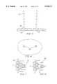
- FIG. 15provides an enlarged cross-sectional side view of the supply container 74 including an integrally-formed discharge nozzle 76 attached at a side wall of the container 74.
- the nozzleincludes a rear surface 77 in fluid communication with fluid inside the supply container 74 and a front surface 79 positioned in close proximity to the vibrating free surface 37.
Landscapes
- Health & Medical Sciences (AREA)
- Engineering & Computer Science (AREA)
- Life Sciences & Earth Sciences (AREA)
- General Health & Medical Sciences (AREA)
- Veterinary Medicine (AREA)
- Hematology (AREA)
- Biomedical Technology (AREA)
- Animal Behavior & Ethology (AREA)
- Anesthesiology (AREA)
- Public Health (AREA)
- Heart & Thoracic Surgery (AREA)
- Bioinformatics & Cheminformatics (AREA)
- Pulmonology (AREA)
- Biophysics (AREA)
- Mechanical Engineering (AREA)
- Special Spraying Apparatus (AREA)
- Nozzles (AREA)
Abstract
Description
Claims (31)
Priority Applications (21)
| Application Number | Priority Date | Filing Date | Title |
|---|---|---|---|
| US08/417,311US5938117A (en) | 1991-04-24 | 1995-04-05 | Methods and apparatus for dispensing liquids as an atomized spray |
| DE69633122TDE69633122T2 (en) | 1995-04-05 | 1996-04-03 | METHOD AND DEVICE FOR DELIVERING LIQUIDS AS ATOMIZED SPRAY |
| AU54421/96AAU5442196A (en) | 1995-04-05 | 1996-04-03 | Methods and apparatus for dispensing liquids as an atomized spray |
| EP96911579AEP0822865B1 (en) | 1995-04-05 | 1996-04-03 | Methods and apparatus for dispensing liquids as an atomized spray |
| PCT/US1996/004646WO1996031289A1 (en) | 1993-12-07 | 1996-04-03 | Methods and apparatus for dispensing liquids as an atomized spray |
| US09/149,426US6205999B1 (en) | 1995-04-05 | 1998-09-08 | Methods and apparatus for storing chemical compounds in a portable inhaler |
| US09/313,914US6755189B2 (en) | 1995-04-05 | 1999-05-18 | Methods and apparatus for storing chemical compounds in a portable inhaler |
| US09/318,552US6540153B1 (en) | 1991-04-24 | 1999-05-27 | Methods and apparatus for dispensing liquids as an atomized spray |
| US09/483,096US6427682B1 (en) | 1995-04-05 | 2000-01-14 | Methods and apparatus for aerosolizing a substance |
| US09/574,168US6467476B1 (en) | 1995-04-05 | 2000-05-18 | Liquid dispensing apparatus and methods |
| US09/678,410US6540154B1 (en) | 1991-04-24 | 2000-10-02 | Systems and methods for controlling fluid feed to an aerosol generator |
| US09/812,988US6782886B2 (en) | 1995-04-05 | 2001-03-20 | Metering pumps for an aerosolizer |
| US09/970,335US20020121274A1 (en) | 1995-04-05 | 2001-10-02 | Laminated electroformed aperture plate |
| US10/201,341US6814071B2 (en) | 1995-04-05 | 2002-07-22 | Methods and apparatus for aerosolizing a substance |
| US10/222,178US6640804B2 (en) | 1995-04-05 | 2002-08-15 | Liquid dispensing apparatus and methods |
| US10/394,510US6921020B2 (en) | 1991-04-24 | 2003-03-21 | Method and apparatus for dispensing liquids as an atomized spray |
| US10/394,512US7040549B2 (en) | 1991-04-24 | 2003-03-21 | Systems and methods for controlling fluid feed to an aerosol generator |
| US10/655,642US7174888B2 (en) | 1995-04-05 | 2003-09-05 | Liquid dispensing apparatus and methods |
| US11/147,982US7083112B2 (en) | 1991-04-24 | 2005-06-06 | Method and apparatus for dispensing liquids as an atomized spray |
| US11/418,841US7628339B2 (en) | 1991-04-24 | 2006-05-05 | Systems and methods for controlling fluid feed to an aerosol generator |
| US11/674,089US8561604B2 (en) | 1995-04-05 | 2007-02-12 | Liquid dispensing apparatus and methods |
Applications Claiming Priority (4)
| Application Number | Priority Date | Filing Date | Title |
|---|---|---|---|
| US07/691,584US5164740A (en) | 1991-04-24 | 1991-04-24 | High frequency printing mechanism |
| US72677791A | 1991-07-08 | 1991-07-08 | |
| US08/163,850US6629646B1 (en) | 1991-04-24 | 1993-12-07 | Droplet ejector with oscillating tapered aperture |
| US08/417,311US5938117A (en) | 1991-04-24 | 1995-04-05 | Methods and apparatus for dispensing liquids as an atomized spray |
Related Parent Applications (2)
| Application Number | Title | Priority Date | Filing Date |
|---|---|---|---|
| US08/163,850Continuation-In-PartUS6629646B1 (en) | 1991-04-24 | 1993-12-07 | Droplet ejector with oscillating tapered aperture |
| US08/521,641Continuation-In-PartUS5586550A (en) | 1995-04-05 | 1995-08-31 | Apparatus and methods for the delivery of therapeutic liquids to the respiratory system |
Related Child Applications (11)
| Application Number | Title | Priority Date | Filing Date |
|---|---|---|---|
| US08/604,313ContinuationUS5758637A (en) | 1995-04-05 | 1996-02-21 | Liquid dispensing apparatus and methods |
| US08/604,313Continuation-In-PartUS5758637A (en) | 1995-04-05 | 1996-02-21 | Liquid dispensing apparatus and methods |
| US09/095,737ContinuationUS6014970A (en) | 1995-04-05 | 1998-06-11 | Methods and apparatus for storing chemical compounds in a portable inhaler |
| US09/095,737Continuation-In-PartUS6014970A (en) | 1995-04-05 | 1998-06-11 | Methods and apparatus for storing chemical compounds in a portable inhaler |
| US09/149,426Continuation-In-PartUS6205999B1 (en) | 1995-04-05 | 1998-09-08 | Methods and apparatus for storing chemical compounds in a portable inhaler |
| US09/149,426ContinuationUS6205999B1 (en) | 1995-04-05 | 1998-09-08 | Methods and apparatus for storing chemical compounds in a portable inhaler |
| US09/318,552ContinuationUS6540153B1 (en) | 1991-04-24 | 1999-05-27 | Methods and apparatus for dispensing liquids as an atomized spray |
| US09/318,552Continuation-In-PartUS6540153B1 (en) | 1991-04-24 | 1999-05-27 | Methods and apparatus for dispensing liquids as an atomized spray |
| US09/574,168ContinuationUS6467476B1 (en) | 1995-04-05 | 2000-05-18 | Liquid dispensing apparatus and methods |
| US10/394,510Continuation-In-PartUS6921020B2 (en) | 1991-04-24 | 2003-03-21 | Method and apparatus for dispensing liquids as an atomized spray |
| US10/655,642Continuation-In-PartUS7174888B2 (en) | 1995-04-05 | 2003-09-05 | Liquid dispensing apparatus and methods |
Publications (1)
| Publication Number | Publication Date |
|---|---|
| US5938117Atrue US5938117A (en) | 1999-08-17 |
Family
ID=23653446
Family Applications (4)
| Application Number | Title | Priority Date | Filing Date |
|---|---|---|---|
| US08/417,311Expired - LifetimeUS5938117A (en) | 1991-04-24 | 1995-04-05 | Methods and apparatus for dispensing liquids as an atomized spray |
| US09/318,552Expired - Fee RelatedUS6540153B1 (en) | 1991-04-24 | 1999-05-27 | Methods and apparatus for dispensing liquids as an atomized spray |
| US10/394,510Expired - Fee RelatedUS6921020B2 (en) | 1991-04-24 | 2003-03-21 | Method and apparatus for dispensing liquids as an atomized spray |
| US11/147,982Expired - Fee RelatedUS7083112B2 (en) | 1991-04-24 | 2005-06-06 | Method and apparatus for dispensing liquids as an atomized spray |
Family Applications After (3)
| Application Number | Title | Priority Date | Filing Date |
|---|---|---|---|
| US09/318,552Expired - Fee RelatedUS6540153B1 (en) | 1991-04-24 | 1999-05-27 | Methods and apparatus for dispensing liquids as an atomized spray |
| US10/394,510Expired - Fee RelatedUS6921020B2 (en) | 1991-04-24 | 2003-03-21 | Method and apparatus for dispensing liquids as an atomized spray |
| US11/147,982Expired - Fee RelatedUS7083112B2 (en) | 1991-04-24 | 2005-06-06 | Method and apparatus for dispensing liquids as an atomized spray |
Country Status (5)
| Country | Link |
|---|---|
| US (4) | US5938117A (en) |
| EP (1) | EP0822865B1 (en) |
| AU (1) | AU5442196A (en) |
| DE (1) | DE69633122T2 (en) |
| WO (1) | WO1996031289A1 (en) |
Cited By (178)
| Publication number | Priority date | Publication date | Assignee | Title |
|---|---|---|---|---|
| WO1999063946A3 (en)* | 1998-06-11 | 2000-02-03 | Aerogen Inc | Improved methods and apparatus for storing chemical compounds in a portable inhaler |
| US6293474B1 (en) | 1999-03-08 | 2001-09-25 | S. C. Johnson & Son, Inc. | Delivery system for dispensing volatiles |
| US6296196B1 (en) | 1999-03-05 | 2001-10-02 | S. C. Johnson & Son, Inc. | Control system for atomizing liquids with a piezoelectric vibrator |
| WO2001085244A1 (en) | 2000-05-05 | 2001-11-15 | Aerogen (Ireland) Limited | Apparatus and methods for the delivery of medicaments to the respiratory system |
| US6341732B1 (en)* | 2000-06-19 | 2002-01-29 | S. C. Johnson & Son, Inc. | Method and apparatus for maintaining control of liquid flow in a vibratory atomizing device |
| WO2002009888A1 (en) | 2000-07-31 | 2002-02-07 | S.C. Johnson & Son, Inc. | Method and apparatus for dispensing liquids in aerosolized form with minimum spillage |
| US6379633B1 (en)* | 2000-02-04 | 2002-04-30 | Holographic Engineering Llc | Super-charged ozoneated fog for surface sterilization |
| US6378780B1 (en) | 1999-02-09 | 2002-04-30 | S. C. Johnson & Son, Inc. | Delivery system for dispensing volatiles |
| US6382522B2 (en) | 1999-03-08 | 2002-05-07 | S. C. Johnson & Son, Inc. | Attachment method for piezoelectric elements |
| WO2002036269A1 (en) | 2000-10-30 | 2002-05-10 | Instrumentarium Corporation | Device and method for detecting and controlling liquid supply to an apparatus discharging liquid |
| EP1219314A1 (en) | 2000-12-29 | 2002-07-03 | Instrumentarium Corporation | Liquid discharge apparatus having magnetic valve |
| EP1219313A1 (en) | 2000-12-29 | 2002-07-03 | Instrumentarium Corporation | Liquid discharging apparatus and magneto-shape-memory type valve |
| US20020104895A1 (en)* | 2001-02-07 | 2002-08-08 | Firmin Garcia | Fluid product dispenser |
| US20020121274A1 (en)* | 1995-04-05 | 2002-09-05 | Aerogen, Inc. | Laminated electroformed aperture plate |
| WO2002074374A1 (en) | 2001-03-20 | 2002-09-26 | Aerogen, Inc. | Fluid filled ampoules and methods for their use in aerosolizers |
| US6467476B1 (en) | 1995-04-05 | 2002-10-22 | Aerogen, Inc. | Liquid dispensing apparatus and methods |
| WO2002087773A1 (en)* | 2001-05-02 | 2002-11-07 | Aerogen, Inc. | Insert molded aerosol generator and methods |
| US6482863B2 (en) | 2000-12-15 | 2002-11-19 | S. C. Johnson & Son, Inc. | Insect repellant formulation deliverable by piezoelectric device |
| WO2002097270A1 (en)* | 2001-05-25 | 2002-12-05 | The Technology Partnership Plc | Micropump |
| US6508411B1 (en)* | 1999-03-31 | 2003-01-21 | Ngk Insulators, Ltd. | Method of driving liquid-drop spraying device |
| US6540153B1 (en) | 1991-04-24 | 2003-04-01 | Aerogen, Inc. | Methods and apparatus for dispensing liquids as an atomized spray |
| US6540154B1 (en)* | 1991-04-24 | 2003-04-01 | Aerogen, Inc. | Systems and methods for controlling fluid feed to an aerosol generator |
| US6543443B1 (en) | 2000-07-12 | 2003-04-08 | Aerogen, Inc. | Methods and devices for nebulizing fluids |
| US6546927B2 (en) | 2001-03-13 | 2003-04-15 | Aerogen, Inc. | Methods and apparatus for controlling piezoelectric vibration |
| US6550691B2 (en)* | 2001-05-22 | 2003-04-22 | Steve Pence | Reagent dispenser head |
| US6550472B2 (en) | 2001-03-16 | 2003-04-22 | Aerogen, Inc. | Devices and methods for nebulizing fluids using flow directors |
| WO2003059424A1 (en) | 2002-01-15 | 2003-07-24 | Aerogen, Inc. | Methods and systems for operating an aerosol generator |
| US20030192959A1 (en)* | 2002-03-05 | 2003-10-16 | Microflow Engineering Sa | Method and system for ambient air scenting and disinfecting based on flexible, autonomous liquid atomizer cartridges and an intelligent networking thereof |
| US20030235536A1 (en)* | 2002-03-15 | 2003-12-25 | The Brigham And Women's Hospital, Inc. | Central airway administration for systemic delivery of therapeutics |
| US6685302B2 (en) | 2001-10-31 | 2004-02-03 | Hewlett-Packard Development Company, L.P. | Flextensional transducer and method of forming a flextensional transducer |
| US6702196B2 (en) | 1999-03-31 | 2004-03-09 | Ngk Insulators, Ltd. | Circuit for driving liquid drop spraying apparatus |
| US20040050947A1 (en)* | 2002-05-20 | 2004-03-18 | Aerogen, Inc. | Apparatus for providing aerosol for medical treatment and methods |
| US20040063912A1 (en)* | 2002-03-15 | 2004-04-01 | The Brigham And Women's Hospital, Inc. | Central airway administration for systemic delivery of therapeutics |
| US6732944B2 (en) | 2001-05-02 | 2004-05-11 | Aerogen, Inc. | Base isolated nebulizing device and methods |
| US20040140374A1 (en)* | 2002-12-30 | 2004-07-22 | Nektar Therapeutics | Prefilming atomizer |
| US6782886B2 (en) | 1995-04-05 | 2004-08-31 | Aerogen, Inc. | Metering pumps for an aerosolizer |
| US6802460B2 (en) | 2002-03-05 | 2004-10-12 | Microflow Engineering Sa | Method and system for ambient air scenting and disinfecting based on flexible, autonomous liquid atomizer cartridges and an intelligent networking thereof |
| US20040200907A1 (en)* | 2003-04-14 | 2004-10-14 | Martens Edward J. | Atomizer wicking system |
| US6948491B2 (en) | 2001-03-20 | 2005-09-27 | Aerogen, Inc. | Convertible fluid feed system with comformable reservoir and methods |
| US20050263149A1 (en)* | 2002-09-19 | 2005-12-01 | Noymer Peter D | Aerosol drug delivery system employing formulation pre-heating |
| US20050263608A1 (en)* | 1991-04-24 | 2005-12-01 | Aerogen, Inc. | Droplet ejector with oscillating tapered aperture |
| US20060097068A1 (en)* | 2002-08-02 | 2006-05-11 | Markus Urich | Fluid droplet production apparatus and method |
| US7090830B2 (en) | 2001-05-24 | 2006-08-15 | Alexza Pharmaceuticals, Inc. | Drug condensation aerosols and kits |
| US20060198941A1 (en)* | 2005-03-04 | 2006-09-07 | Niall Behan | Method of coating a medical appliance utilizing a vibrating mesh nebulizer, a system for coating a medical appliance, and a medical appliance produced by the method |
| US20060198942A1 (en)* | 2005-03-04 | 2006-09-07 | O'connor Timothy | System and method for coating a medical appliance utilizing a vibrating mesh nebulizer |
| US20060198940A1 (en)* | 2005-03-04 | 2006-09-07 | Mcmorrow David | Method of producing particles utilizing a vibrating mesh nebulizer for coating a medical appliance, a system for producing particles, and a medical appliance |
| WO2006102345A2 (en) | 2005-03-24 | 2006-09-28 | Aerogen, Inc. | Methods and systems for operating an aerosol generator |
| US20060238757A1 (en)* | 2005-02-09 | 2006-10-26 | Silcott David B | Method and system for detecting, classifying and identifying particles |
| WO2007030162A2 (en) | 2005-05-18 | 2007-03-15 | Nektar Therapeutics | Valves, devices, and methods for endobronchial therapy |
| US7201167B2 (en) | 2004-04-20 | 2007-04-10 | Aerogen, Inc. | Method and composition for the treatment of lung surfactant deficiency or dysfunction |
| US20070209659A1 (en)* | 1995-04-05 | 2007-09-13 | Aerogen, Inc. | Liquid dispensing apparatus and methods |
| US7290541B2 (en) | 2004-04-20 | 2007-11-06 | Aerogen, Inc. | Aerosol delivery apparatus and method for pressure-assisted breathing systems |
| US20080001129A1 (en)* | 2006-07-01 | 2008-01-03 | Lloyd Weaver | Mass impact claw bar |
| US7360536B2 (en) | 2002-01-07 | 2008-04-22 | Aerogen, Inc. | Devices and methods for nebulizing fluids for inhalation |
| US20080135643A1 (en)* | 2006-12-08 | 2008-06-12 | Kimberly-Clark Worldwide, Inc. | Pulsating spray dispensers |
| US7389943B2 (en) | 2004-06-30 | 2008-06-24 | S.C. Johnson & Son, Inc. | Electromechanical apparatus for dispensing volatile substances with single dispensing mechanism and cartridge for holding multiple receptacles |
| US20080216828A1 (en)* | 2007-03-09 | 2008-09-11 | Alexza Pharmaceuticals, Inc. | Heating unit for use in a drug delivery device |
| WO2008117265A1 (en) | 2007-03-28 | 2008-10-02 | Stamford Devices Limited | Humidification in breathing circuits |
| US7458374B2 (en) | 2002-05-13 | 2008-12-02 | Alexza Pharmaceuticals, Inc. | Method and apparatus for vaporizing a compound |
| US7469844B2 (en) | 2002-11-08 | 2008-12-30 | S.C. Johnson & Son, Inc. | Diffusion device and method of diffusing |
| US20090044787A1 (en)* | 2007-08-15 | 2009-02-19 | Adams Georg B L | Efficient Reduced-Emissions Carburetor |
| US20090044786A1 (en)* | 2007-08-15 | 2009-02-19 | Adams Georg B L | Efficient Reduced-Emissions Carburetor |
| US7537009B2 (en) | 2001-06-05 | 2009-05-26 | Alexza Pharmaceuticals, Inc. | Method of forming an aerosol for inhalation delivery |
| US7540286B2 (en) | 2004-06-03 | 2009-06-02 | Alexza Pharmaceuticals, Inc. | Multiple dose condensation aerosol devices and methods of forming condensation aerosols |
| US7581540B2 (en) | 2004-08-12 | 2009-09-01 | Alexza Pharmaceuticals, Inc. | Aerosol drug delivery device incorporating percussively activated heat packages |
| US7585493B2 (en) | 2001-05-24 | 2009-09-08 | Alexza Pharmaceuticals, Inc. | Thin-film drug delivery article and method of use |
| WO2009111612A1 (en)* | 2008-03-07 | 2009-09-11 | Novartis Ag | Aerosolization device |
| WO2009118718A1 (en)* | 2008-03-28 | 2009-10-01 | Stamford Devices Limited | Ηumidification in breathin circuits |
| US20090241948A1 (en)* | 2007-03-28 | 2009-10-01 | Dermot Joseph Clancy | Humidification in breathing circuits |
| US7600511B2 (en)* | 2001-11-01 | 2009-10-13 | Novartis Pharma Ag | Apparatus and methods for delivery of medicament to a respiratory system |
| US7622073B2 (en) | 2005-04-12 | 2009-11-24 | S.C. Johnson & Son, Inc. | Apparatus for and method of dispensing active materials |
| US7628339B2 (en) | 1991-04-24 | 2009-12-08 | Novartis Pharma Ag | Systems and methods for controlling fluid feed to an aerosol generator |
| US7645442B2 (en) | 2001-05-24 | 2010-01-12 | Alexza Pharmaceuticals, Inc. | Rapid-heating drug delivery article and method of use |
| US7677467B2 (en) | 2002-01-07 | 2010-03-16 | Novartis Pharma Ag | Methods and devices for aerosolizing medicament |
| US20100126502A1 (en)* | 2005-08-23 | 2010-05-27 | Aerogen, Inc. | Self-sealing t-piece and valved t-piece |
| DE102009010565B3 (en)* | 2009-02-18 | 2010-09-02 | Ing. Erich Pfeiffer Gmbh | discharge |
| US20100282247A1 (en)* | 2007-09-25 | 2010-11-11 | Novartis Ag | Treatment of pulmonary disorders with aerosolized medicaments such as vancomycin |
| WO2011009131A1 (en) | 2009-07-17 | 2011-01-20 | Nektar Therapeutics | Negatively biased sealed nebulizers systems and methods |
| US7883031B2 (en) | 2003-05-20 | 2011-02-08 | James F. Collins, Jr. | Ophthalmic drug delivery system |
| WO2011018777A1 (en) | 2009-08-10 | 2011-02-17 | Aerosurgical Limited | An insufflation system |
| US7909033B2 (en) | 2006-05-03 | 2011-03-22 | Comedica Incorporated | Breathing treatment apparatus |
| US7913688B2 (en) | 2002-11-27 | 2011-03-29 | Alexza Pharmaceuticals, Inc. | Inhalation device for producing a drug aerosol |
| US20110108025A1 (en)* | 2008-04-04 | 2011-05-12 | Nektar Therapeutics | Aerosolization device |
| WO2011058477A1 (en) | 2009-11-11 | 2011-05-19 | Koninklijke Philips Electronics N.V. | Drug delivery apparatus and method |
| US7946291B2 (en) | 2004-04-20 | 2011-05-24 | Novartis Ag | Ventilation systems and methods employing aerosol generators |
| US20110168170A1 (en)* | 2010-01-12 | 2011-07-14 | Dance Pharmaceuticals, Inc. | Preservative free insulin formulations and systems and methods for aerosolizing |
| US20110171312A1 (en)* | 2008-09-19 | 2011-07-14 | Nektar Therapeutics | Modified therapeutic peptides, methods of their preparation and use |
| US20110168172A1 (en)* | 2010-01-12 | 2011-07-14 | Dance Pharmaceuticals, Inc. | Preservative-free single dose inhaler systems |
| US7981401B2 (en) | 2002-11-26 | 2011-07-19 | Alexza Pharmaceuticals, Inc. | Diuretic aerosols and methods of making and using them |
| WO2011098552A2 (en) | 2010-02-11 | 2011-08-18 | Ablynx Nv | Methods and compositions for the preparation of aerosols |
| US8012136B2 (en) | 2003-05-20 | 2011-09-06 | Optimyst Systems, Inc. | Ophthalmic fluid delivery device and method of operation |
| EP2371409A1 (en) | 2010-03-31 | 2011-10-05 | AeroSurgical Limited | Insufflation of body cavities |
| US8051854B2 (en) | 2006-09-15 | 2011-11-08 | Comedica Incorporated | Continuous high-frequency oscillation breathing treatment apparatus |
| EP2457609A1 (en)* | 2010-11-24 | 2012-05-30 | PARI Pharma GmbH | Aerosol generator |
| US8235037B2 (en) | 2001-05-24 | 2012-08-07 | Alexza Pharmaceuticals, Inc. | Drug condensation aerosols and kits |
| US8267081B2 (en) | 2009-02-20 | 2012-09-18 | Baxter International Inc. | Inhaled anesthetic agent therapy and delivery system |
| US8336545B2 (en) | 2000-05-05 | 2012-12-25 | Novartis Pharma Ag | Methods and systems for operating an aerosol generator |
| US8348177B2 (en) | 2008-06-17 | 2013-01-08 | Davicon Corporation | Liquid dispensing apparatus using a passive liquid metering method |
| US8387612B2 (en) | 2003-05-21 | 2013-03-05 | Alexza Pharmaceuticals, Inc. | Self-contained heating unit and drug-supply unit employing same |
| US8398001B2 (en) | 1999-09-09 | 2013-03-19 | Novartis Ag | Aperture plate and methods for its construction and use |
| US20130074832A1 (en)* | 2005-02-11 | 2013-03-28 | Pari Pharma Gmbh | Aerosol generating means for inhalation therapy devices |
| US8551036B2 (en) | 2009-08-10 | 2013-10-08 | Aerosurgical Limited | Insufflation system |
| WO2013158353A1 (en) | 2012-04-16 | 2013-10-24 | Dance Pharmaceuticals, Inc. | Methods and systems for supplying aerosolization devices with liquid medicaments |
| US8574630B2 (en) | 2010-09-22 | 2013-11-05 | Map Pharmaceuticals, Inc. | Corticosteroid particles and method of production |
| US8616195B2 (en) | 2003-07-18 | 2013-12-31 | Novartis Ag | Nebuliser for the production of aerosolized medication |
| US8684980B2 (en) | 2010-07-15 | 2014-04-01 | Corinthian Ophthalmic, Inc. | Drop generating device |
| US8733935B2 (en) | 2010-07-15 | 2014-05-27 | Corinthian Ophthalmic, Inc. | Method and system for performing remote treatment and monitoring |
| US8967493B2 (en) | 2010-06-15 | 2015-03-03 | Aptar Radolfzell Gmbh | Atomizing device |
| US9050434B2 (en) | 2007-05-18 | 2015-06-09 | Comedica Incorporated | Lung therapy device |
| US9068566B2 (en) | 2011-01-21 | 2015-06-30 | Biodot, Inc. | Piezoelectric dispenser with a longitudinal transducer and replaceable capillary tube |
| US9087145B2 (en) | 2010-07-15 | 2015-07-21 | Eyenovia, Inc. | Ophthalmic drug delivery |
| US9108211B2 (en) | 2005-05-25 | 2015-08-18 | Nektar Therapeutics | Vibration systems and methods |
| US9151425B2 (en) | 2009-11-02 | 2015-10-06 | Comedica Incorporated | Multiple conduit connector apparatus and method |
| US9272101B2 (en) | 2010-01-19 | 2016-03-01 | Nektar Therapeutics | Identifying dry nebulizer elements |
| US9393336B2 (en) | 2011-07-08 | 2016-07-19 | S. C. Johnson & Son, Inc. | Insert for dispensing a compressed gas product, system with such an insert, and method of dispensing a compressed gas product |
| CN105828957A (en)* | 2013-12-19 | 2016-08-03 | 皇家飞利浦有限公司 | An assembly for use in a liquid droplet apparatus |
| US20160258430A1 (en)* | 2013-10-24 | 2016-09-08 | Universite Sciences Technologies Lille | Method for generating a flow of fluid |
| US9545488B2 (en) | 2010-01-12 | 2017-01-17 | Dance Biopharm Inc. | Preservative-free single dose inhaler systems |
| US9572950B2 (en) | 2008-09-26 | 2017-02-21 | Stamford Devices Limited | Supplemental oxygen delivery system |
| US9572596B2 (en) | 2011-06-30 | 2017-02-21 | Covidien Lp | Applicators for controlled in situ delivery of therapeutic compositions and implants, methods of fabrication and use |
| US9642980B2 (en) | 2013-03-15 | 2017-05-09 | Trudell Medical International | Ventilator circuit, adapter for use in ventilator circuit and methods for the use thereof |
| US9682153B2 (en) | 2008-09-19 | 2017-06-20 | Nektar Therapeutics | Polymer conjugates of therapeutic peptides |
| WO2017127420A1 (en) | 2016-01-19 | 2017-07-27 | Nektar Therapeutics | Sealed liquid reservoir for a nebulizer |
| US9795752B2 (en) | 2012-12-03 | 2017-10-24 | Mhs Care-Innovation, Llc | Combination respiratory therapy device, system, and method |
| WO2017191108A1 (en) | 2016-05-02 | 2017-11-09 | Ablynx Nv | Treatment of rsv infection |
| WO2017192771A1 (en)* | 2016-05-03 | 2017-11-09 | Pneuma Respiratory, Inc. | Methods for generating and delivering droplets to the pulmonary system using a droplet delivery device |
| US9962507B2 (en) | 2016-05-03 | 2018-05-08 | Pneuma Respiratory, Inc. | Droplet delivery device for delivery of fluids to the pulmonary system and methods of use |
| WO2018099968A1 (en) | 2016-11-29 | 2018-06-07 | Ablynx N.V. | Treatment of infection by respiratory syncytial virus (rsv) |
| US10154923B2 (en) | 2010-07-15 | 2018-12-18 | Eyenovia, Inc. | Drop generating device |
| US10307550B2 (en) | 2014-06-09 | 2019-06-04 | Dance Biopharm Inc. | Liquid drug cartridges and associated dispenser |
| US10471222B2 (en) | 2014-07-01 | 2019-11-12 | Dance Biopharm Inc. | Aerosolization system with flow restrictor and feedback device |
| US10525214B2 (en) | 2010-01-12 | 2020-01-07 | Dance Biopharm Inc. | Preservative-free single dose inhaler system |
| US10569033B2 (en) | 2013-04-16 | 2020-02-25 | Dance Biopharm Inc. | Liquid dispensing and methods for dispensing liquids |
| US10583038B2 (en) | 2015-04-10 | 2020-03-10 | Kedalion Therapeutics | Piezoelectric dispenser with replaceable ampoule |
| US10624781B2 (en) | 2015-01-12 | 2020-04-21 | Kedalion Therapeutics, Inc. | Micro-droplet delivery device and methods |
| US10639194B2 (en) | 2011-12-12 | 2020-05-05 | Eyenovia, Inc. | High modulus polymeric ejector mechanism, ejector device, and methods of use |
| US10842951B2 (en) | 2010-01-12 | 2020-11-24 | Aerami Therapeutics, Inc. | Liquid insulin formulations and methods relating thereto |
| US10857313B2 (en) | 2014-07-01 | 2020-12-08 | Aerami Therapeutics, Inc. | Liquid nebulization systems and methods |
| US10888454B2 (en) | 2017-01-20 | 2021-01-12 | Kedalion Therapeutics, Inc. | Piezoelectric fluid dispenser |
| US10888117B2 (en) | 2018-10-18 | 2021-01-12 | Respira Technologies, Inc. | Apparatus for producing an aerosol for inhalation by a person |
| US10905837B2 (en) | 2015-04-02 | 2021-02-02 | Hill-Rom Services Pte. Ltd. | Respiratory therapy cycle control and feedback |
| WO2021023522A1 (en) | 2019-08-02 | 2021-02-11 | Stamford Devices Limited | Buccal administration of aerosol |
| WO2021023596A1 (en) | 2019-08-02 | 2021-02-11 | Stamford Devices Limited | Control of nebuliser output |
| US20210131684A1 (en)* | 2013-07-19 | 2021-05-06 | Ademco Inc. | Humidifier system |
| US11096990B2 (en) | 2015-02-25 | 2021-08-24 | Aerami Therapeutics, Inc. | Liquid insulin formulations and methods relating thereto |
| US11273271B2 (en) | 2014-07-01 | 2022-03-15 | Aerami Therapeutics, Inc. | Aerosolization system with flow restrictor and feedback device |
| US11278448B2 (en) | 2017-12-08 | 2022-03-22 | Kedalion Therapeutics, Inc. | Fluid delivery alignment system |
| US11285274B2 (en) | 2016-05-03 | 2022-03-29 | Pneuma Respiratory, Inc. | Methods for the systemic delivery of therapeutic agents to the pulmonary system using a droplet delivery device |
| US11285285B2 (en) | 2016-05-03 | 2022-03-29 | Pneuma Respiratory, Inc. | Systems and methods comprising a droplet delivery device and a breathing assist device for therapeutic treatment |
| US11285284B2 (en) | 2016-05-03 | 2022-03-29 | Pneuma Respiratory, Inc. | Methods for treatment of pulmonary lung diseases with improved therapeutic efficacy and improved dose efficiency |
| US20220226587A1 (en)* | 2019-05-09 | 2022-07-21 | Pneuma Respiratory, Inc. | Ultrasonic breath actuated respiratory droplet delivery device and methods of use |
| US11433212B1 (en) | 2021-10-07 | 2022-09-06 | Health Micro Devices Corporation | Self-contained face mask system with automatic droplet dispenser for humidification |
| US20220296823A1 (en)* | 2019-06-27 | 2022-09-22 | Pneuma Respiratory, Inc. | Delivery of small droplets to the respiratory system via electronic breath actuated droplet delivery device |
| US11458267B2 (en) | 2017-10-17 | 2022-10-04 | Pneuma Respiratory, Inc. | Nasal drug delivery apparatus and methods of use |
| US11517685B2 (en) | 2019-01-18 | 2022-12-06 | Qnovia, Inc. | Electronic device for producing an aerosol for inhalation by a person |
| US11529476B2 (en) | 2017-05-19 | 2022-12-20 | Pneuma Respiratory, Inc. | Dry powder delivery device and methods of use |
| US11679028B2 (en) | 2019-03-06 | 2023-06-20 | Novartis Ag | Multi-dose ocular fluid delivery system |
| US11690963B2 (en) | 2018-08-22 | 2023-07-04 | Qnovia, Inc. | Electronic device for producing an aerosol for inhalation by a person |
| US11738158B2 (en) | 2017-10-04 | 2023-08-29 | Pneuma Respiratory, Inc. | Electronic breath actuated in-line droplet delivery device and methods of use |
| US11771852B2 (en) | 2017-11-08 | 2023-10-03 | Pneuma Respiratory, Inc. | Electronic breath actuated in-line droplet delivery device with small volume ampoule and methods of use |
| US11793945B2 (en) | 2021-06-22 | 2023-10-24 | Pneuma Respiratory, Inc. | Droplet delivery device with push ejection |
| US11925577B2 (en) | 2020-04-17 | 2024-03-12 | Bausch + Lomb Ireland Limted | Hydrodynamically actuated preservative free dispensing system |
| US11938057B2 (en) | 2020-04-17 | 2024-03-26 | Bausch + Lomb Ireland Limited | Hydrodynamically actuated preservative free dispensing system |
| US11938056B2 (en) | 2017-06-10 | 2024-03-26 | Eyenovia, Inc. | Methods and devices for handling a fluid and delivering the fluid to the eye |
| US12070554B2 (en) | 2019-11-11 | 2024-08-27 | Hill-Rom Services Pte. Ltd. | Pneumatic connector apparatus and method |
| US12080401B2 (en) | 2012-12-03 | 2024-09-03 | Metrohealth Ventures Llc | Combination respiratory therapy device, system and method |
| US12090087B2 (en) | 2020-04-17 | 2024-09-17 | Bausch + Lomb Ireland Limited | Hydrodynamically actuated preservative free dispensing system having a collapsible liquid reservoir |
| US12097145B2 (en) | 2019-03-06 | 2024-09-24 | Bausch + Lomb Ireland Limited | Vented multi-dose ocular fluid delivery system |
| US12156547B2 (en) | 2018-08-22 | 2024-12-03 | Qnovia, Inc. | Electronic device for producing an aerosol for inhalation by a person |
| US12161585B2 (en) | 2019-12-11 | 2024-12-10 | Eyenovia, Inc. | Systems and devices for delivering fluids to the eye and methods of use |
| US12161795B2 (en) | 2022-07-18 | 2024-12-10 | Pneuma Respiratory, Inc. | Small step size and high resolution aerosol generation system and method |
| US12171932B2 (en) | 2017-08-02 | 2024-12-24 | Medline Industries, Lp | Medical nebulizer for fast drug delivery |
| US12186234B2 (en) | 2018-04-12 | 2025-01-07 | Bausch + Lomb Ireland Limited | Topical ocular delivery methods and devices for use in the same |
| US12214119B2 (en) | 2018-02-02 | 2025-02-04 | Alexza Pharmaceuticals, Inc. | Electrical condensation aerosol device |
| US12279650B2 (en) | 2022-04-22 | 2025-04-22 | Qnovia, Inc. | Electronic devices for aerosolizing and inhaling liquid having an enclosed interior air passageway with diaphragm and pressure sensor |
| US12290472B2 (en) | 2020-04-17 | 2025-05-06 | Bausch + Lomb Ireland Limited | Hydrodynamically actuated preservative free dispensing system |
| US12295881B2 (en) | 2018-07-03 | 2025-05-13 | Bausch + Lomb Ireland Limited | Topical ocular delivery devices and methods for using the same |
| US12350194B1 (en) | 2018-04-12 | 2025-07-08 | Bausch + Lomb Ireland Limited | Topical ocular delivery of fluids with controlled mass dosing and wireless communication |
Families Citing this family (63)
| Publication number | Priority date | Publication date | Assignee | Title |
|---|---|---|---|---|
| HUP9800508A1 (en) | 1998-03-09 | 2000-02-28 | György Hegedűs | Device for vibratory dispensing of liquid |
| GB2335628B (en)* | 1998-03-19 | 2001-09-05 | The Technology Partnership Plc | Droplet generator and method of operating a droplet generator |
| GB9827262D0 (en)* | 1998-12-10 | 1999-02-03 | The Technology Parternership Plc | Switchable spray generator and method of operation |
| GB9916532D0 (en) | 1999-07-14 | 1999-09-15 | Videojet Systems Int | A droplet generator for a continuous stream ink jet print head |
| US6450419B1 (en)* | 2000-10-27 | 2002-09-17 | S.C. Johnson & Son, Inc. | Self contained liquid atomizer assembly |
| US20030116641A1 (en)* | 2001-10-02 | 2003-06-26 | Ngk Insulators, Ltd. | Liquid injection apparatus |
| US20070044792A1 (en)* | 2005-08-30 | 2007-03-01 | Aerogen, Inc. | Aerosol generators with enhanced corrosion resistance |
| US7095019B1 (en) | 2003-05-30 | 2006-08-22 | Chem-Space Associates, Inc. | Remote reagent chemical ionization source |
| US7195179B2 (en)* | 2003-06-01 | 2007-03-27 | Piezo Technologies | Piezoelectric mist generation device |
| US20050127206A1 (en)* | 2003-12-10 | 2005-06-16 | Xerox Corporation | Device and system for dispensing fluids into the atmosphere |
| ATE510566T1 (en)* | 2004-01-26 | 2011-06-15 | Ep Systems Sa | LIQUID ATOMIZATION SYSTEM |
| US7824627B2 (en) | 2004-02-03 | 2010-11-02 | S.C. Johnson & Son, Inc. | Active material and light emitting device |
| WO2005074999A1 (en) | 2004-02-03 | 2005-08-18 | S.C. Johnson & Son, Inc. | Device providing coordinated emission of light and volatile active |
| GB2412869A (en)* | 2004-04-07 | 2005-10-12 | Reckitt Benckiser | Electronic drive system for a droplet spray generation device |
| US20070210183A1 (en)* | 2004-04-20 | 2007-09-13 | Xerox Corporation | Environmental system including a micromechanical dispensing device |
| EP1740242A4 (en)* | 2004-04-20 | 2009-12-23 | Aerogen Inc | Aerosol delivery apparatus, methods and compositions for pressure-assisted breathing systems |
| EP1604701B1 (en)* | 2004-06-09 | 2010-12-15 | Microflow Engineering SA | Improved modular liquid spray system |
| DE102004049574A1 (en)* | 2004-10-12 | 2006-04-20 | Doris Dr. Barnikol-Keuten | Drugs and System for Percutaneous Drug Delivery |
| FR2877241B1 (en)* | 2004-10-29 | 2007-08-24 | Osmooze Sa | NEBULATOR COMPRISING MEANS FOR PRESSURIZING A NEBULIZING LIQUID |
| TWI268179B (en)* | 2005-04-12 | 2006-12-11 | Ind Tech Res Inst | Improved structure of atomizing nozzle the plate can be vibrated by the vibrator element to compress the fluid, so that the fluid is jet from the perforations in form of tiny particle |
| US7138626B1 (en) | 2005-05-05 | 2006-11-21 | Eai Corporation | Method and device for non-contact sampling and detection |
| US7568401B1 (en) | 2005-06-20 | 2009-08-04 | Science Applications International Corporation | Sample tube holder |
| TWI285443B (en)* | 2005-09-13 | 2007-08-11 | Sondlin Technology Corp | Filtrated LED mosquito lamp with mosquito bait |
| US7576322B2 (en)* | 2005-11-08 | 2009-08-18 | Science Applications International Corporation | Non-contact detector system with plasma ion source |
| TWI279256B (en)* | 2005-12-13 | 2007-04-21 | Ind Tech Res Inst | A compact spray cooling module |
| US20080110453A1 (en)* | 2006-11-15 | 2008-05-15 | Delphi Technologies Inc. | Nebulizer and methods for controlling the nebulizer |
| US20080110452A1 (en)* | 2006-11-15 | 2008-05-15 | Delphi Technologies Inc. | Nebulizer and method for controlling an amount of liquid that is atomized by the nebulizer |
| US20080156320A1 (en)* | 2007-01-03 | 2008-07-03 | Thomas Low | Ultrasonic nebulizer and method for atomizing liquid |
| US20080197213A1 (en)* | 2007-02-20 | 2008-08-21 | Flashinski Stanley J | Active material diffuser and method of providing and using same |
| US20090235925A1 (en)* | 2007-03-28 | 2009-09-24 | John Sylvester Power | Aerosolisation system |
| US20090240192A1 (en)* | 2007-03-28 | 2009-09-24 | John Sylvester Power | Insufflation of body cavities |
| US7926467B2 (en)* | 2007-04-30 | 2011-04-19 | Caterpillar Inc. | Droplet generator for engine system |
| US8123396B1 (en) | 2007-05-16 | 2012-02-28 | Science Applications International Corporation | Method and means for precision mixing |
| US8296993B2 (en) | 2007-11-16 | 2012-10-30 | Monster Mosquito Systems, Llc | Ultrasonic humidifier for repelling insects |
| US7712249B1 (en) | 2007-11-16 | 2010-05-11 | Monster Mosquito Systems, Llc | Ultrasonic humidifier for repelling insects |
| US8008617B1 (en) | 2007-12-28 | 2011-08-30 | Science Applications International Corporation | Ion transfer device |
| US20090212133A1 (en)* | 2008-01-25 | 2009-08-27 | Collins Jr James F | Ophthalmic fluid delivery device and method of operation |
| WO2009118717A1 (en)* | 2008-03-28 | 2009-10-01 | Stamford Devices Limited | Insufflation of body cavities |
| US7891580B2 (en)* | 2008-04-30 | 2011-02-22 | S.C. Johnson & Son, Inc. | High volume atomizer for common consumer spray products |
| US7815798B2 (en)* | 2008-07-10 | 2010-10-19 | Agilent Technologies, Inc. | Discrete drop dispensing device and method of use |
| US8071957B1 (en) | 2009-03-10 | 2011-12-06 | Science Applications International Corporation | Soft chemical ionization source |
| US8465263B2 (en)* | 2009-06-22 | 2013-06-18 | Wagner Spray Tech Corporation | Dynamic control of an electric drive |
| US20110100360A1 (en)* | 2009-11-02 | 2011-05-05 | Joseph Dee Faram | Composite lung therapy device and method |
| US8627845B2 (en)* | 2010-02-26 | 2014-01-14 | Auto-Mark, Inc. | Directional conduit guide support |
| JP2011177407A (en)* | 2010-03-03 | 2011-09-15 | Seiko Epson Corp | Fluid injection device |
| AU2013245946A1 (en) | 2012-04-10 | 2014-11-27 | Eyenovia, Inc. | Spray ejector mechanisms and devices providing charge isolation and controllable droplet charge, and low dosage volume opthalmic administration |
| CN109011046B (en) | 2012-04-20 | 2021-10-01 | 艾诺维亚股份有限公司 | Device for delivering a fluid to a target |
| EA201492094A1 (en) | 2012-05-15 | 2015-04-30 | Айновиа, Инк. | EJECTOR DEVICES, METHODS, PATTERNS AND SCHEMES FOR THEM |
| US9452271B2 (en) | 2013-05-29 | 2016-09-27 | General Electric Company | Nebulizer systems and methods |
| AU2014316769B2 (en)* | 2013-09-09 | 2018-12-06 | Omnimist, Ltd. | Atomizing spray apparatus |
| CN103721329B (en)* | 2013-12-12 | 2015-11-11 | 科迈(常州)电子有限公司 | Humidification oxygen inhalation device |
| CA2977519A1 (en) | 2015-02-27 | 2016-09-01 | Board Of Regents, The University Of Texas System | Nebulized cav-1 polypeptide therapeutics and uses thereof |
| WO2017041130A1 (en)* | 2015-09-07 | 2017-03-16 | Monash University | Device and method for droplet ejection |
| US12042809B2 (en)* | 2015-11-02 | 2024-07-23 | Altria Client Services Llc | Aerosol-generating system comprising a vibratable element |
| FR3043576B1 (en)* | 2015-11-18 | 2020-09-18 | Areco Finances Et Tech Arfitec | MINIATURIZED SPRAYING DEVICE WITH PIEZOELECTRIC TRANSDUCER |
| DE102018220405A1 (en)* | 2017-12-06 | 2019-06-06 | Robert Bosch Gmbh | Media applicator |
| BR112021004404A2 (en) | 2018-09-10 | 2021-08-03 | Lung Therapeutics, Inc. | fragments of modified peptides of the cav-1 protein and their use in the treatment of fibrosis |
| US20220160814A1 (en) | 2019-03-11 | 2022-05-26 | Lung Therapeutics, Inc. | Compositions and methods for protecting type 2 alveolar epithelial cells (aec2) |
| US20230331673A1 (en) | 2020-06-27 | 2023-10-19 | Crescenta Biosciences | Composition of compounds that modulate cell metabolism and methods of use |
| WO2022229403A1 (en)* | 2021-04-30 | 2022-11-03 | Jt International Sa | Liquid jet inhalation device |
| US12138243B2 (en) | 2021-12-31 | 2024-11-12 | Crescenta Biosciences | Antiviral use of FABP4 modulating compounds |
| US20230364633A1 (en)* | 2022-05-12 | 2023-11-16 | GM Global Technology Operations LLC | Acoustic softening of non-newtonian material |
| PL243802B1 (en)* | 2023-01-16 | 2023-10-16 | Lubelska Polt | System for regulated dosing of fragrances into the air |
Citations (91)
| Publication number | Priority date | Publication date | Assignee | Title |
|---|---|---|---|---|
| US2101304A (en)* | 1936-06-05 | 1937-12-07 | Sheaffer W A Pen Co | Fountain pen |
| US2158615A (en)* | 1937-07-26 | 1939-05-16 | Sheaffer W A Pen Co | Fountain pen |
| US2187528A (en)* | 1937-06-07 | 1940-01-16 | Russell T Wing | Fountain pen |
| US2223541A (en)* | 1939-01-06 | 1940-12-03 | Parker Pen Co | Fountain pen |
| US2283333A (en)* | 1941-05-22 | 1942-05-19 | Sheaffer W A Pen Co | Fountain pen |
| US2292381A (en)* | 1940-12-24 | 1942-08-11 | Esterbrook Steel Pen Mfg Co | Fountain pen feed |
| US2360297A (en)* | 1944-04-10 | 1944-10-10 | Russell T Wing | Fountain pen |
| US2375770A (en)* | 1943-11-19 | 1945-05-15 | Arthur O Dahiberg | Fountain pen |
| US2404063A (en)* | 1944-04-27 | 1946-07-16 | Parker Pen Co | Fountain pen |
| US2430023A (en)* | 1944-01-27 | 1947-11-04 | Esterbrook Pen Co | Writing implement |
| US2474996A (en)* | 1945-10-12 | 1949-07-05 | Sheaffer W A Pen Co | Fountain pen |
| US2512004A (en)* | 1945-03-05 | 1950-06-20 | Russell T Wing | Fountain pen |
| US2521657A (en)* | 1944-07-07 | 1950-09-05 | Scripto Inc | Fountain pen |
| US2681041A (en)* | 1946-06-08 | 1954-06-15 | Parker Pen Co | Fountain pen |
| US2779623A (en)* | 1954-09-10 | 1957-01-29 | Bernard J Eisenkraft | Electromechanical atomizer |
| US2935970A (en)* | 1955-03-23 | 1960-05-10 | Sapphire Products Inc | Fountain pen ink reservoir |
| GB973458A (en)* | 1962-10-16 | 1964-10-28 | Exxon Research Engineering Co | Improvements in or relating to methods and apparatus for atomising liquids |
| US3411854A (en)* | 1965-04-30 | 1968-11-19 | Montblanc Simplo Gmbh | Ink conductor for fountain pens |
| US3558052A (en)* | 1968-10-31 | 1971-01-26 | F I N D Inc | Method and apparatus for spraying electrostatic dry powder |
| US3738574A (en)* | 1971-06-15 | 1973-06-12 | Siemens Ag | Apparatus for atomizing fluids with a piezoelectrically stimulated oscillator system |
| US3790079A (en)* | 1972-06-05 | 1974-02-05 | Rnb Ass Inc | Method and apparatus for generating monodisperse aerosol |
| US3804329A (en)* | 1973-07-27 | 1974-04-16 | J Martner | Ultrasonic generator and atomizer apparatus and method |
| US3812854A (en)* | 1972-10-20 | 1974-05-28 | A Michaels | Ultrasonic nebulizer |
| US3950760A (en)* | 1973-12-12 | 1976-04-13 | U.S. Philips Corporation | Device for writing with liquid ink |
| US3958249A (en)* | 1974-12-18 | 1976-05-18 | International Business Machines Corporation | Ink jet drop generator |
| US3983740A (en)* | 1971-12-07 | 1976-10-05 | Societe Grenobloise D'etudes Et D'applications Hydrauliques (Sogreah) | Method and apparatus for forming a stream of identical drops at very high speed |
| GB1454597A (en)* | 1973-05-07 | 1976-11-03 | Voest Ag | Method of prilling and device for carrying out the method |
| US4005435A (en)* | 1975-05-15 | 1977-01-25 | Burroughs Corporation | Liquid jet droplet generator |
| US4159803A (en)* | 1977-03-31 | 1979-07-03 | MistO2 Gen Equipment Company | Chamber for ultrasonic aerosol generation |
| US4240081A (en)* | 1978-10-13 | 1980-12-16 | Dennison Manufacturing Company | Ink jet printing |
| US4261512A (en)* | 1979-02-24 | 1981-04-14 | Boehringer Ingelheim Gmbh | Inhalation aerosol spray device |
| US4294407A (en)* | 1978-12-19 | 1981-10-13 | Bosch-Siemens Hausgerate Gmbh | Atomizer for fluids, preferably an inhalation device |
| GB2073616A (en)* | 1980-04-12 | 1981-10-21 | Leybold Heraeus Gmbh & Co Kg | Apparatus for atomising liquids |
| US4300546A (en)* | 1978-11-15 | 1981-11-17 | Carl Heyer Gmbh Inhalationstechnik | Hand-held atomizer especially for dispensing inhalation-administered medicaments |
| JPS5723852A (en)* | 1980-07-18 | 1982-02-08 | Shimadzu Corp | Electrophoretic measuring device |
| EP0049636A1 (en)* | 1980-10-06 | 1982-04-14 | Matsushita Electric Industrial Co., Ltd. | Electric liquid atomizing apparatus |
| US4334531A (en)* | 1979-06-19 | 1982-06-15 | Bosch-Siemens Hausgerate Gmbh | Inhalator |
| US4336544A (en)* | 1980-08-18 | 1982-06-22 | Hewlett-Packard Company | Method and apparatus for drop-on-demand ink jet printing |
| JPS57105608A (en)* | 1980-12-22 | 1982-07-01 | Matsushita Electric Ind Co Ltd | Atomizer |
| US4338576A (en)* | 1978-07-26 | 1982-07-06 | Tdk Electronics Co., Ltd. | Ultrasonic atomizer unit utilizing shielded and grounded elements |
| US4368476A (en)* | 1979-12-19 | 1983-01-11 | Canon Kabushiki Kaisha | Ink jet recording head |
| JPS5861857A (en)* | 1981-10-09 | 1983-04-13 | Matsushita Electric Works Ltd | Liquid atomizer |
| US4389071A (en)* | 1980-12-12 | 1983-06-21 | Hydronautics, Inc. | Enhancing liquid jet erosion |
| JPS58139757A (en)* | 1982-02-16 | 1983-08-19 | Matsushita Electric Ind Co Ltd | Atomizer |
| US4408719A (en)* | 1981-06-17 | 1983-10-11 | Last Anthony J | Sonic liquid atomizer |
| US4431136A (en)* | 1980-03-17 | 1984-02-14 | Kraftwerk Union Aktiengesellschaft | Slit nozzle and fast-acting shutoff valve |
| EP0103161A2 (en)* | 1982-08-11 | 1984-03-21 | Linde Aktiengesellschaft | Process for simultaneously filling a plurality of acetylene-filled bottles with a solvent |
| US4474251A (en)* | 1980-12-12 | 1984-10-02 | Hydronautics, Incorporated | Enhancing liquid jet erosion |
| US4474326A (en)* | 1981-11-24 | 1984-10-02 | Tdk Electronics Co., Ltd. | Ultrasonic atomizing device |
| US4475113A (en)* | 1981-06-18 | 1984-10-02 | International Business Machines | Drop-on-demand method and apparatus using converging nozzles and high viscosity fluids |
| JPS604714A (en)* | 1983-06-23 | 1985-01-11 | Matsushita Electric Ind Co Ltd | atomization device |
| EP0134847A1 (en)* | 1983-08-02 | 1985-03-27 | Trutek Research Inc. | Inhalation valve |
| US4530464A (en)* | 1982-07-14 | 1985-07-23 | Matsushita Electric Industrial Co., Ltd. | Ultrasonic liquid ejecting unit and method for making same |
| US4533082A (en)* | 1981-10-15 | 1985-08-06 | Matsushita Electric Industrial Company, Limited | Piezoelectric oscillated nozzle |
| US4539575A (en)* | 1983-06-06 | 1985-09-03 | Siemens Aktiengesellschaft | Recorder operating with liquid drops and comprising elongates piezoelectric transducers rigidly connected at both ends with a jet orifice plate |
| US4544933A (en)* | 1983-09-20 | 1985-10-01 | Siemens Aktiengesellschaft | Apparatus and method for ink droplet ejection for a printer |
| US4546361A (en)* | 1982-10-26 | 1985-10-08 | Ing. C. Olivetti & C., S.P.A. | Ink jet printing method and device |
| US4550325A (en)* | 1984-12-26 | 1985-10-29 | Polaroid Corporation | Drop dispensing device |
| JPS618357A (en)* | 1984-06-22 | 1986-01-16 | Toshiba Corp | dot printer |
| US4591883A (en)* | 1982-03-31 | 1986-05-27 | Ricoh Company, Ltd. | Ink-jet printer head |
| US4593291A (en)* | 1984-04-16 | 1986-06-03 | Exxon Research And Engineering Co. | Method for operating an ink jet device to obtain high resolution printing |
| US4605167A (en)* | 1982-01-18 | 1986-08-12 | Matsushita Electric Industrial Company, Limited | Ultrasonic liquid ejecting apparatus |
| JPS61215059A (en)* | 1985-03-22 | 1986-09-24 | Toshiba Corp | Ink jet recording apparatus |
| US4620201A (en)* | 1985-01-14 | 1986-10-28 | Siemens Aktiengesellschaft | Magnetic driver ink jet |
| US4628890A (en)* | 1984-08-31 | 1986-12-16 | Freeman Winifer W | Fuel atomizer |
| US4632311A (en)* | 1982-12-20 | 1986-12-30 | Matsushita Electric Industrial Co., Ltd. | Atomizing apparatus employing a capacitive piezoelectric transducer |
| GB2177623A (en)* | 1985-07-11 | 1987-01-28 | Bosch Gmbh Robert | Ultrasonic atomiser |
| US4659014A (en)* | 1985-09-05 | 1987-04-21 | Delavan Corporation | Ultrasonic spray nozzle and method |
| US4702418A (en)* | 1985-09-09 | 1987-10-27 | Piezo Electric Products, Inc. | Aerosol dispenser |
| US4753579A (en)* | 1986-01-22 | 1988-06-28 | Piezo Electric Products, Inc. | Ultrasonic resonant device |
| US4790479A (en)* | 1984-09-07 | 1988-12-13 | Omron Tateisi Electronics Co. | Oscillating construction for an ultrasonic atomizer inhaler |
| US4793339A (en)* | 1984-08-29 | 1988-12-27 | Omron Tateisi Electronics Co. | Ultrasonic atomizer and storage bottle and nozzle therefor |
| US4796807A (en)* | 1987-03-17 | 1989-01-10 | Lechler Gmbh & C. Kg | Ultrasonic atomizer for liquids |
| US4799622A (en)* | 1986-08-05 | 1989-01-24 | Tao Nenryo Kogyo Kabushiki Kaisha | Ultrasonic atomizing apparatus |
| US4828886A (en)* | 1986-11-05 | 1989-05-09 | U.S. Philips Corporation | Method of applying small drop-shaped quantities of melted solder from a nozzle to surfaces to be wetted and device for carrying out the method |
| US4850534A (en)* | 1987-05-30 | 1989-07-25 | Tdk Corporation | Ultrasonic wave nebulizer |
| US4865006A (en)* | 1987-03-20 | 1989-09-12 | Hitachi, Ltd. | Liquid atomizer |
| US4888516A (en)* | 1987-07-22 | 1989-12-19 | Siemens Aktiengesellschaft | Piezoelectrically excitable resonance system |
| JPH02135169A (en)* | 1988-11-15 | 1990-05-24 | Matsushita Electric Works Ltd | Ultrasonic atomizer |
| JPH02189161A (en)* | 1989-01-14 | 1990-07-25 | Matsushita Electric Works Ltd | Ultrasonic type spray device |
| US5021701A (en)* | 1988-10-20 | 1991-06-04 | Tdk Corporation | Piezoelectric vibrator mounting system for a nebulizer |
| GB2240494A (en)* | 1989-12-12 | 1991-08-07 | Bespak Plc | Atomised spray dispenser |
| US5063396A (en)* | 1989-03-14 | 1991-11-05 | Seiko Epson Corporation | Droplets jetting device |
| WO1992011050A1 (en)* | 1990-12-17 | 1992-07-09 | Minnesota Mining And Manufacturing Company | Inhaler |
| US5164740A (en)* | 1991-04-24 | 1992-11-17 | Yehuda Ivri | High frequency printing mechanism |
| WO1993001404A1 (en)* | 1991-07-08 | 1993-01-21 | Yehuda Ivri | Ultrasonic fluid ejector |
| US5198157A (en)* | 1990-08-20 | 1993-03-30 | Dynamad S. A. R. L. | Ultrasonic device for the continuous production of particles |
| US5297734A (en)* | 1990-10-11 | 1994-03-29 | Toda Koji | Ultrasonic vibrating device |
| US5299739A (en)* | 1991-05-27 | 1994-04-05 | Tdk Corporation | Ultrasonic wave nebulizer |
| GB2272389A (en)* | 1992-11-04 | 1994-05-18 | Bespak Plc | Dispensing apparatus |
| US5518179A (en)* | 1991-12-04 | 1996-05-21 | The Technology Partnership Limited | Fluid droplets production apparatus and method |
Family Cites Families (8)
| Publication number | Priority date | Publication date | Assignee | Title |
|---|---|---|---|---|
| JPS607721A (en) | 1983-06-28 | 1985-01-16 | Toshiba Corp | Manufacture of compound semiconductor device |
| US5129579A (en)* | 1990-10-25 | 1992-07-14 | Sun Microsystems, Inc. | Vacuum attachment for electronic flux nozzle |
| US5938117A (en) | 1991-04-24 | 1999-08-17 | Aerogen, Inc. | Methods and apparatus for dispensing liquids as an atomized spray |
| US6629646B1 (en) | 1991-04-24 | 2003-10-07 | Aerogen, Inc. | Droplet ejector with oscillating tapered aperture |
| FR2692569B1 (en) | 1992-06-18 | 1996-08-30 | Valois | METHOD AND DEVICE FOR FILLING A FLUID SUBSTANCE METER DISPENSER. |
| JPH067721A (en) | 1992-06-26 | 1994-01-18 | Koji Toda | Ultrasonic spraying apparatus |
| GB9418870D0 (en) | 1994-09-19 | 1994-11-09 | Minnesota Mining & Mfg | Aerosol dispenser comprising contents indicator |
| FR2743313B1 (en)* | 1996-01-04 | 1998-02-06 | Imra Europe Sa | HIGH-YIELD SPRAYING DEVICE, ESPECIALLY MICRO-DROPLET WATER |
- 1995
- 1995-04-05USUS08/417,311patent/US5938117A/ennot_activeExpired - Lifetime
- 1996
- 1996-04-03DEDE69633122Tpatent/DE69633122T2/ennot_activeExpired - Lifetime
- 1996-04-03EPEP96911579Apatent/EP0822865B1/ennot_activeExpired - Lifetime
- 1996-04-03AUAU54421/96Apatent/AU5442196A/ennot_activeAbandoned
- 1996-04-03WOPCT/US1996/004646patent/WO1996031289A1/enactiveIP Right Grant
- 1999
- 1999-05-27USUS09/318,552patent/US6540153B1/ennot_activeExpired - Fee Related
- 2003
- 2003-03-21USUS10/394,510patent/US6921020B2/ennot_activeExpired - Fee Related
- 2005
- 2005-06-06USUS11/147,982patent/US7083112B2/ennot_activeExpired - Fee Related
Patent Citations (97)
| Publication number | Priority date | Publication date | Assignee | Title |
|---|---|---|---|---|
| US2101304A (en)* | 1936-06-05 | 1937-12-07 | Sheaffer W A Pen Co | Fountain pen |
| US2187528A (en)* | 1937-06-07 | 1940-01-16 | Russell T Wing | Fountain pen |
| US2158615A (en)* | 1937-07-26 | 1939-05-16 | Sheaffer W A Pen Co | Fountain pen |
| US2223541A (en)* | 1939-01-06 | 1940-12-03 | Parker Pen Co | Fountain pen |
| US2292381A (en)* | 1940-12-24 | 1942-08-11 | Esterbrook Steel Pen Mfg Co | Fountain pen feed |
| US2283333A (en)* | 1941-05-22 | 1942-05-19 | Sheaffer W A Pen Co | Fountain pen |
| US2375770A (en)* | 1943-11-19 | 1945-05-15 | Arthur O Dahiberg | Fountain pen |
| US2430023A (en)* | 1944-01-27 | 1947-11-04 | Esterbrook Pen Co | Writing implement |
| US2360297A (en)* | 1944-04-10 | 1944-10-10 | Russell T Wing | Fountain pen |
| US2404063A (en)* | 1944-04-27 | 1946-07-16 | Parker Pen Co | Fountain pen |
| US2521657A (en)* | 1944-07-07 | 1950-09-05 | Scripto Inc | Fountain pen |
| US2512004A (en)* | 1945-03-05 | 1950-06-20 | Russell T Wing | Fountain pen |
| US2474996A (en)* | 1945-10-12 | 1949-07-05 | Sheaffer W A Pen Co | Fountain pen |
| US2681041A (en)* | 1946-06-08 | 1954-06-15 | Parker Pen Co | Fountain pen |
| US2779623A (en)* | 1954-09-10 | 1957-01-29 | Bernard J Eisenkraft | Electromechanical atomizer |
| US2935970A (en)* | 1955-03-23 | 1960-05-10 | Sapphire Products Inc | Fountain pen ink reservoir |
| GB973458A (en)* | 1962-10-16 | 1964-10-28 | Exxon Research Engineering Co | Improvements in or relating to methods and apparatus for atomising liquids |
| US3411854A (en)* | 1965-04-30 | 1968-11-19 | Montblanc Simplo Gmbh | Ink conductor for fountain pens |
| US3558052A (en)* | 1968-10-31 | 1971-01-26 | F I N D Inc | Method and apparatus for spraying electrostatic dry powder |
| US3738574A (en)* | 1971-06-15 | 1973-06-12 | Siemens Ag | Apparatus for atomizing fluids with a piezoelectrically stimulated oscillator system |
| US3983740A (en)* | 1971-12-07 | 1976-10-05 | Societe Grenobloise D'etudes Et D'applications Hydrauliques (Sogreah) | Method and apparatus for forming a stream of identical drops at very high speed |
| US3790079A (en)* | 1972-06-05 | 1974-02-05 | Rnb Ass Inc | Method and apparatus for generating monodisperse aerosol |
| US3812854A (en)* | 1972-10-20 | 1974-05-28 | A Michaels | Ultrasonic nebulizer |
| GB1454597A (en)* | 1973-05-07 | 1976-11-03 | Voest Ag | Method of prilling and device for carrying out the method |
| US3804329A (en)* | 1973-07-27 | 1974-04-16 | J Martner | Ultrasonic generator and atomizer apparatus and method |
| US3950760A (en)* | 1973-12-12 | 1976-04-13 | U.S. Philips Corporation | Device for writing with liquid ink |
| US3958249A (en)* | 1974-12-18 | 1976-05-18 | International Business Machines Corporation | Ink jet drop generator |
| US4005435A (en)* | 1975-05-15 | 1977-01-25 | Burroughs Corporation | Liquid jet droplet generator |
| US4159803A (en)* | 1977-03-31 | 1979-07-03 | MistO2 Gen Equipment Company | Chamber for ultrasonic aerosol generation |
| US4338576A (en)* | 1978-07-26 | 1982-07-06 | Tdk Electronics Co., Ltd. | Ultrasonic atomizer unit utilizing shielded and grounded elements |
| US4240081A (en)* | 1978-10-13 | 1980-12-16 | Dennison Manufacturing Company | Ink jet printing |
| US4300546A (en)* | 1978-11-15 | 1981-11-17 | Carl Heyer Gmbh Inhalationstechnik | Hand-held atomizer especially for dispensing inhalation-administered medicaments |
| US4294407A (en)* | 1978-12-19 | 1981-10-13 | Bosch-Siemens Hausgerate Gmbh | Atomizer for fluids, preferably an inhalation device |
| US4261512A (en)* | 1979-02-24 | 1981-04-14 | Boehringer Ingelheim Gmbh | Inhalation aerosol spray device |
| US4334531A (en)* | 1979-06-19 | 1982-06-15 | Bosch-Siemens Hausgerate Gmbh | Inhalator |
| US4368476A (en)* | 1979-12-19 | 1983-01-11 | Canon Kabushiki Kaisha | Ink jet recording head |
| US4431136A (en)* | 1980-03-17 | 1984-02-14 | Kraftwerk Union Aktiengesellschaft | Slit nozzle and fast-acting shutoff valve |
| GB2073616A (en)* | 1980-04-12 | 1981-10-21 | Leybold Heraeus Gmbh & Co Kg | Apparatus for atomising liquids |
| JPS5723852A (en)* | 1980-07-18 | 1982-02-08 | Shimadzu Corp | Electrophoretic measuring device |
| US4336544A (en)* | 1980-08-18 | 1982-06-22 | Hewlett-Packard Company | Method and apparatus for drop-on-demand ink jet printing |
| EP0049636A1 (en)* | 1980-10-06 | 1982-04-14 | Matsushita Electric Industrial Co., Ltd. | Electric liquid atomizing apparatus |
| US4465234A (en)* | 1980-10-06 | 1984-08-14 | Matsushita Electric Industrial Co., Ltd. | Liquid atomizer including vibrator |
| US4474251A (en)* | 1980-12-12 | 1984-10-02 | Hydronautics, Incorporated | Enhancing liquid jet erosion |
| US4389071A (en)* | 1980-12-12 | 1983-06-21 | Hydronautics, Inc. | Enhancing liquid jet erosion |
| US4681264A (en)* | 1980-12-12 | 1987-07-21 | Hydronautics, Incorporated | Enhancing liquid jet erosion |
| JPS57105608A (en)* | 1980-12-22 | 1982-07-01 | Matsushita Electric Ind Co Ltd | Atomizer |
| US4408719A (en)* | 1981-06-17 | 1983-10-11 | Last Anthony J | Sonic liquid atomizer |
| US4475113A (en)* | 1981-06-18 | 1984-10-02 | International Business Machines | Drop-on-demand method and apparatus using converging nozzles and high viscosity fluids |
| US4479609A (en)* | 1981-10-09 | 1984-10-30 | Matsushita Electric Works, Ltd. | Liquid sprayer |
| JPS5861857A (en)* | 1981-10-09 | 1983-04-13 | Matsushita Electric Works Ltd | Liquid atomizer |
| US4533082A (en)* | 1981-10-15 | 1985-08-06 | Matsushita Electric Industrial Company, Limited | Piezoelectric oscillated nozzle |
| US4474326A (en)* | 1981-11-24 | 1984-10-02 | Tdk Electronics Co., Ltd. | Ultrasonic atomizing device |
| US4605167A (en)* | 1982-01-18 | 1986-08-12 | Matsushita Electric Industrial Company, Limited | Ultrasonic liquid ejecting apparatus |
| JPS58139757A (en)* | 1982-02-16 | 1983-08-19 | Matsushita Electric Ind Co Ltd | Atomizer |
| US4591883A (en)* | 1982-03-31 | 1986-05-27 | Ricoh Company, Ltd. | Ink-jet printer head |
| US4530464A (en)* | 1982-07-14 | 1985-07-23 | Matsushita Electric Industrial Co., Ltd. | Ultrasonic liquid ejecting unit and method for making same |
| EP0103161A2 (en)* | 1982-08-11 | 1984-03-21 | Linde Aktiengesellschaft | Process for simultaneously filling a plurality of acetylene-filled bottles with a solvent |
| US4546361A (en)* | 1982-10-26 | 1985-10-08 | Ing. C. Olivetti & C., S.P.A. | Ink jet printing method and device |
| US4632311A (en)* | 1982-12-20 | 1986-12-30 | Matsushita Electric Industrial Co., Ltd. | Atomizing apparatus employing a capacitive piezoelectric transducer |
| US4539575A (en)* | 1983-06-06 | 1985-09-03 | Siemens Aktiengesellschaft | Recorder operating with liquid drops and comprising elongates piezoelectric transducers rigidly connected at both ends with a jet orifice plate |
| JPS604714A (en)* | 1983-06-23 | 1985-01-11 | Matsushita Electric Ind Co Ltd | atomization device |
| EP0134847A1 (en)* | 1983-08-02 | 1985-03-27 | Trutek Research Inc. | Inhalation valve |
| US4544933A (en)* | 1983-09-20 | 1985-10-01 | Siemens Aktiengesellschaft | Apparatus and method for ink droplet ejection for a printer |
| US4593291A (en)* | 1984-04-16 | 1986-06-03 | Exxon Research And Engineering Co. | Method for operating an ink jet device to obtain high resolution printing |
| JPS618357A (en)* | 1984-06-22 | 1986-01-16 | Toshiba Corp | dot printer |
| US4793339A (en)* | 1984-08-29 | 1988-12-27 | Omron Tateisi Electronics Co. | Ultrasonic atomizer and storage bottle and nozzle therefor |
| US4628890A (en)* | 1984-08-31 | 1986-12-16 | Freeman Winifer W | Fuel atomizer |
| US4790479A (en)* | 1984-09-07 | 1988-12-13 | Omron Tateisi Electronics Co. | Oscillating construction for an ultrasonic atomizer inhaler |
| US4550325A (en)* | 1984-12-26 | 1985-10-29 | Polaroid Corporation | Drop dispensing device |
| US4620201A (en)* | 1985-01-14 | 1986-10-28 | Siemens Aktiengesellschaft | Magnetic driver ink jet |
| JPS61215059A (en)* | 1985-03-22 | 1986-09-24 | Toshiba Corp | Ink jet recording apparatus |
| GB2177623A (en)* | 1985-07-11 | 1987-01-28 | Bosch Gmbh Robert | Ultrasonic atomiser |
| US4659014A (en)* | 1985-09-05 | 1987-04-21 | Delavan Corporation | Ultrasonic spray nozzle and method |
| US4702418A (en)* | 1985-09-09 | 1987-10-27 | Piezo Electric Products, Inc. | Aerosol dispenser |
| US4753579A (en)* | 1986-01-22 | 1988-06-28 | Piezo Electric Products, Inc. | Ultrasonic resonant device |
| US4799622A (en)* | 1986-08-05 | 1989-01-24 | Tao Nenryo Kogyo Kabushiki Kaisha | Ultrasonic atomizing apparatus |
| US4828886A (en)* | 1986-11-05 | 1989-05-09 | U.S. Philips Corporation | Method of applying small drop-shaped quantities of melted solder from a nozzle to surfaces to be wetted and device for carrying out the method |
| US4796807A (en)* | 1987-03-17 | 1989-01-10 | Lechler Gmbh & C. Kg | Ultrasonic atomizer for liquids |
| US4865006A (en)* | 1987-03-20 | 1989-09-12 | Hitachi, Ltd. | Liquid atomizer |
| US4850534A (en)* | 1987-05-30 | 1989-07-25 | Tdk Corporation | Ultrasonic wave nebulizer |
| US4888516A (en)* | 1987-07-22 | 1989-12-19 | Siemens Aktiengesellschaft | Piezoelectrically excitable resonance system |
| US5021701A (en)* | 1988-10-20 | 1991-06-04 | Tdk Corporation | Piezoelectric vibrator mounting system for a nebulizer |
| JPH02135169A (en)* | 1988-11-15 | 1990-05-24 | Matsushita Electric Works Ltd | Ultrasonic atomizer |
| JPH02189161A (en)* | 1989-01-14 | 1990-07-25 | Matsushita Electric Works Ltd | Ultrasonic type spray device |
| US5063396A (en)* | 1989-03-14 | 1991-11-05 | Seiko Epson Corporation | Droplets jetting device |
| GB2240494A (en)* | 1989-12-12 | 1991-08-07 | Bespak Plc | Atomised spray dispenser |
| US5152456A (en)* | 1989-12-12 | 1992-10-06 | Bespak, Plc | Dispensing apparatus having a perforate outlet member and a vibrating device |
| EP0542723A2 (en)* | 1989-12-12 | 1993-05-19 | Bespak plc | Dispensing apparatus |
| US5261601A (en)* | 1989-12-12 | 1993-11-16 | Bespak Plc | Liquid dispensing apparatus having a vibrating perforate membrane |
| US5198157A (en)* | 1990-08-20 | 1993-03-30 | Dynamad S. A. R. L. | Ultrasonic device for the continuous production of particles |
| US5297734A (en)* | 1990-10-11 | 1994-03-29 | Toda Koji | Ultrasonic vibrating device |
| WO1992011050A1 (en)* | 1990-12-17 | 1992-07-09 | Minnesota Mining And Manufacturing Company | Inhaler |
| US5164740A (en)* | 1991-04-24 | 1992-11-17 | Yehuda Ivri | High frequency printing mechanism |
| US5299739A (en)* | 1991-05-27 | 1994-04-05 | Tdk Corporation | Ultrasonic wave nebulizer |
| WO1993001404A1 (en)* | 1991-07-08 | 1993-01-21 | Yehuda Ivri | Ultrasonic fluid ejector |
| US5518179A (en)* | 1991-12-04 | 1996-05-21 | The Technology Partnership Limited | Fluid droplets production apparatus and method |
| GB2272389A (en)* | 1992-11-04 | 1994-05-18 | Bespak Plc | Dispensing apparatus |
Non-Patent Citations (20)
| Title |
|---|
| Allen, T. Particle Size Measurement. Chapman and Hall pp. 167 169 (1981).* |
| Allen, T. Particle Size Measurement. Chapman and Hall pp. 167-169 (1981). |
| Ashgriz, N., et al. Development of a Controlled Spray Generator. Rev. Sci. Instrum. 58(7):1291 (1987).* |
| Berglund, R.N., et al. Generation of Monodisperse Aerosol Standards. Environ. Sci. Technology 7:2:147 (1973).* |
| Gaiser Tool Company catalog, pp. 26, 29 30 (19 ).* |
| Gaiser Tool Company catalog, pp. 26, 29-30 (19 ). |
| Hikayama, H., et al. Ultrasonic Atomizer with Pump Function. Tech. Rpt. IEICE Japan US88 74:25 (1988).* |
| Hikayama, H., et al. Ultrasonic Atomizer with Pump Function. Tech. Rpt. IEICE Japan US88-74:25 (1988). |
| J. Acoustical Soc. Japan 44:2:116 (1988).* |
| J. Acoustical Soc. Japan 44:6:425 (1988).* |
| Maehara, N., et al. Influence of the Vibrating System of a Multipinhole plate Ultrasonic Nebulizer on Its Performance. Review of Scientific Instruments, 57 (11), Nov. 1986, pp. 2870 2876.* |
| Maehara, N., et al. Influence of the Vibrating System of a Multipinhole-plate Ultrasonic Nebulizer on Its Performance. Review of Scientific Instruments, 57 (11), Nov. 1986, pp. 2870-2876. |
| Maehara, N., et al. Optimum Design Procedure for Multi Pinhole Plate Ultrasonic Atomizer. Japanese Journal of Applied Physics, 26:215 (1987).* |
| Maehara, N., et al. Optimum Design Procedure for Multi-Pinhole-Plate Ultrasonic Atomizer. Japanese Journal of Applied Physics, 26:215 (1987). |
| Nogi, T., et al. Mixture Formation of Fuel Injection System in Gasoline Engine. Nippon Kikai Gakkai Zenkoku Taikai Koenkai Koen Ronbunshu 69:660 (1991).* |
| Siemens AG, 1989, "Ink-Jet Printing: The Present State of the Art," by Wolfgang R. Wehl. |
| Siemens AG, 1989, Ink Jet Printing: The Present State of the Art, by Wolfgang R. Wehl.* |
| TSI Incorporated product catalog. Vibrating Orifice Aerosol Generator (1989).* |
| Ueha, S., et al. Mechanism of Ultrasonic Atomization Using a Multi Pinhole Plate. J. Acoust. Soc. Jpn. (E)6,1:21 (1985).* |
| Ueha, S., et al. Mechanism of Ultrasonic Atomization Using a Multi-Pinhole Plate. J. Acoust. Soc. Jpn. (E)6,1:21 (1985). |
Cited By (317)
| Publication number | Priority date | Publication date | Assignee | Title |
|---|---|---|---|---|
| US20070075161A1 (en)* | 1991-04-24 | 2007-04-05 | Aerogen, Inc. | Droplet Ejector With Oscillating Tapered Aperture |
| US6540153B1 (en) | 1991-04-24 | 2003-04-01 | Aerogen, Inc. | Methods and apparatus for dispensing liquids as an atomized spray |
| US20050263608A1 (en)* | 1991-04-24 | 2005-12-01 | Aerogen, Inc. | Droplet ejector with oscillating tapered aperture |
| US20050279851A1 (en)* | 1991-04-24 | 2005-12-22 | Aerogen, Inc. | Method and apparatus for dispensing liquids as an atomized spray |
| US7628339B2 (en) | 1991-04-24 | 2009-12-08 | Novartis Pharma Ag | Systems and methods for controlling fluid feed to an aerosol generator |
| US7040549B2 (en) | 1991-04-24 | 2006-05-09 | Aerogen, Inc. | Systems and methods for controlling fluid feed to an aerosol generator |
| US6540154B1 (en)* | 1991-04-24 | 2003-04-01 | Aerogen, Inc. | Systems and methods for controlling fluid feed to an aerosol generator |
| US7083112B2 (en) | 1991-04-24 | 2006-08-01 | Aerogen, Inc. | Method and apparatus for dispensing liquids as an atomized spray |
| US7108197B2 (en)* | 1991-04-24 | 2006-09-19 | Aerogen, Inc. | Droplet ejector with oscillating tapered aperture |
| US8561604B2 (en) | 1995-04-05 | 2013-10-22 | Novartis Ag | Liquid dispensing apparatus and methods |
| US6640804B2 (en) | 1995-04-05 | 2003-11-04 | Aerogen, Inc. | Liquid dispensing apparatus and methods |
| US20070209659A1 (en)* | 1995-04-05 | 2007-09-13 | Aerogen, Inc. | Liquid dispensing apparatus and methods |
| US6205999B1 (en)* | 1995-04-05 | 2001-03-27 | Aerogen, Inc. | Methods and apparatus for storing chemical compounds in a portable inhaler |
| US7174888B2 (en) | 1995-04-05 | 2007-02-13 | Aerogen, Inc. | Liquid dispensing apparatus and methods |
| US20020121274A1 (en)* | 1995-04-05 | 2002-09-05 | Aerogen, Inc. | Laminated electroformed aperture plate |
| US6467476B1 (en) | 1995-04-05 | 2002-10-22 | Aerogen, Inc. | Liquid dispensing apparatus and methods |
| US6782886B2 (en) | 1995-04-05 | 2004-08-31 | Aerogen, Inc. | Metering pumps for an aerosolizer |
| US6755189B2 (en) | 1995-04-05 | 2004-06-29 | Aerogen, Inc. | Methods and apparatus for storing chemical compounds in a portable inhaler |
| WO1999063946A3 (en)* | 1998-06-11 | 2000-02-03 | Aerogen Inc | Improved methods and apparatus for storing chemical compounds in a portable inhaler |
| US8578931B2 (en) | 1998-06-11 | 2013-11-12 | Novartis Ag | Methods and apparatus for storing chemical compounds in a portable inhaler |
| US6378780B1 (en) | 1999-02-09 | 2002-04-30 | S. C. Johnson & Son, Inc. | Delivery system for dispensing volatiles |
| US6296196B1 (en) | 1999-03-05 | 2001-10-02 | S. C. Johnson & Son, Inc. | Control system for atomizing liquids with a piezoelectric vibrator |
| US6293474B1 (en) | 1999-03-08 | 2001-09-25 | S. C. Johnson & Son, Inc. | Delivery system for dispensing volatiles |
| US6382522B2 (en) | 1999-03-08 | 2002-05-07 | S. C. Johnson & Son, Inc. | Attachment method for piezoelectric elements |
| US6508411B1 (en)* | 1999-03-31 | 2003-01-21 | Ngk Insulators, Ltd. | Method of driving liquid-drop spraying device |
| US6702196B2 (en) | 1999-03-31 | 2004-03-09 | Ngk Insulators, Ltd. | Circuit for driving liquid drop spraying apparatus |
| US8398001B2 (en) | 1999-09-09 | 2013-03-19 | Novartis Ag | Aperture plate and methods for its construction and use |
| US6537494B2 (en)* | 2000-02-04 | 2003-03-25 | Holographic Engineering Llc | Super-charged ozoneated fog for surface sterilization |
| US6379633B1 (en)* | 2000-02-04 | 2002-04-30 | Holographic Engineering Llc | Super-charged ozoneated fog for surface sterilization |
| US6615824B2 (en) | 2000-05-05 | 2003-09-09 | Aerogen, Inc. | Apparatus and methods for the delivery of medicaments to the respiratory system |
| US7331339B2 (en) | 2000-05-05 | 2008-02-19 | Aerogen, Inc. | Methods and systems for operating an aerosol generator |
| US20030140921A1 (en)* | 2000-05-05 | 2003-07-31 | Aerogen, Inc. | Methods and systems for operating an aerosol generator |
| US7971588B2 (en) | 2000-05-05 | 2011-07-05 | Novartis Ag | Methods and systems for operating an aerosol generator |
| US7748377B2 (en) | 2000-05-05 | 2010-07-06 | Novartis Ag | Methods and systems for operating an aerosol generator |
| WO2001085244A1 (en) | 2000-05-05 | 2001-11-15 | Aerogen (Ireland) Limited | Apparatus and methods for the delivery of medicaments to the respiratory system |
| US8336545B2 (en) | 2000-05-05 | 2012-12-25 | Novartis Pharma Ag | Methods and systems for operating an aerosol generator |
| US6968840B2 (en) | 2000-05-05 | 2005-11-29 | Aerogen, Inc. | Methods and systems for operating an aerosol generator |
| US7322349B2 (en) | 2000-05-05 | 2008-01-29 | Aerogen, Inc. | Apparatus and methods for the delivery of medicaments to the respiratory system |
| AU2001268438B2 (en)* | 2000-06-19 | 2004-12-02 | S.C. Johnson & Son, Inc. | Method and apparatus for maintaining control of liquid flow in a vibratory atomizing device |
| US6341732B1 (en)* | 2000-06-19 | 2002-01-29 | S. C. Johnson & Son, Inc. | Method and apparatus for maintaining control of liquid flow in a vibratory atomizing device |
| US6543443B1 (en) | 2000-07-12 | 2003-04-08 | Aerogen, Inc. | Methods and devices for nebulizing fluids |
| WO2002009888A1 (en) | 2000-07-31 | 2002-02-07 | S.C. Johnson & Son, Inc. | Method and apparatus for dispensing liquids in aerosolized form with minimum spillage |
| US6386462B1 (en) | 2000-07-31 | 2002-05-14 | S. C. Johnson & Son, Inc. | Method and apparatus for dispensing liquids in aerosolized form with minimum spillage |
| WO2002036269A1 (en) | 2000-10-30 | 2002-05-10 | Instrumentarium Corporation | Device and method for detecting and controlling liquid supply to an apparatus discharging liquid |
| US6769626B1 (en) | 2000-10-30 | 2004-08-03 | Instrumentarium Corp. | Device and method for detecting and controlling liquid supply to an apparatus discharging liquids |
| US6482863B2 (en) | 2000-12-15 | 2002-11-19 | S. C. Johnson & Son, Inc. | Insect repellant formulation deliverable by piezoelectric device |
| EP1219314A1 (en) | 2000-12-29 | 2002-07-03 | Instrumentarium Corporation | Liquid discharge apparatus having magnetic valve |
| EP1219313A1 (en) | 2000-12-29 | 2002-07-03 | Instrumentarium Corporation | Liquid discharging apparatus and magneto-shape-memory type valve |
| US6805301B2 (en)* | 2001-02-07 | 2004-10-19 | Valois S.A. | Fluid product dispenser |
| US20020104895A1 (en)* | 2001-02-07 | 2002-08-08 | Firmin Garcia | Fluid product dispenser |
| US6546927B2 (en) | 2001-03-13 | 2003-04-15 | Aerogen, Inc. | Methods and apparatus for controlling piezoelectric vibration |
| US6550472B2 (en) | 2001-03-16 | 2003-04-22 | Aerogen, Inc. | Devices and methods for nebulizing fluids using flow directors |
| US6948491B2 (en) | 2001-03-20 | 2005-09-27 | Aerogen, Inc. | Convertible fluid feed system with comformable reservoir and methods |
| US7032590B2 (en) | 2001-03-20 | 2006-04-25 | Aerogen, Inc. | Fluid filled ampoules and methods for their use in aerosolizers |
| US8196573B2 (en) | 2001-03-20 | 2012-06-12 | Novartis Ag | Methods and systems for operating an aerosol generator |
| US20060169279A1 (en)* | 2001-03-20 | 2006-08-03 | Aerogen, Inc. | Fluid filled ampoules and methods for their use in aerosolizers |
| US7100600B2 (en) | 2001-03-20 | 2006-09-05 | Aerogen, Inc. | Fluid filled ampoules and methods for their use in aerosolizers |
| WO2002074374A1 (en) | 2001-03-20 | 2002-09-26 | Aerogen, Inc. | Fluid filled ampoules and methods for their use in aerosolizers |
| US7195011B2 (en) | 2001-03-20 | 2007-03-27 | Aerogen, Inc. | Convertible fluid feed system with comformable reservoir and methods |
| US6732944B2 (en) | 2001-05-02 | 2004-05-11 | Aerogen, Inc. | Base isolated nebulizing device and methods |
| US6554201B2 (en) | 2001-05-02 | 2003-04-29 | Aerogen, Inc. | Insert molded aerosol generator and methods |
| DE20222021U1 (en) | 2001-05-02 | 2011-08-02 | Novartis Ag | Basic insulated atomizer |
| US6978941B2 (en) | 2001-05-02 | 2005-12-27 | Aerogen, Inc. | Base isolated nebulizing device and methods |
| WO2002087773A1 (en)* | 2001-05-02 | 2002-11-07 | Aerogen, Inc. | Insert molded aerosol generator and methods |
| EP2436450A2 (en) | 2001-05-02 | 2012-04-04 | Novartis AG | Base isolated nebulizing device and methods |
| US7104463B2 (en) | 2001-05-02 | 2006-09-12 | Aerogen, Inc. | Base isolated nebulizing device and methods |
| US6550691B2 (en)* | 2001-05-22 | 2003-04-22 | Steve Pence | Reagent dispenser head |
| US7090830B2 (en) | 2001-05-24 | 2006-08-15 | Alexza Pharmaceuticals, Inc. | Drug condensation aerosols and kits |
| US8235037B2 (en) | 2001-05-24 | 2012-08-07 | Alexza Pharmaceuticals, Inc. | Drug condensation aerosols and kits |
| US10350157B2 (en) | 2001-05-24 | 2019-07-16 | Alexza Pharmaceuticals, Inc. | Drug condensation aerosols and kits |
| US9440034B2 (en) | 2001-05-24 | 2016-09-13 | Alexza Pharmaceuticals, Inc. | Drug condensation aerosols and kits |
| US9211382B2 (en) | 2001-05-24 | 2015-12-15 | Alexza Pharmaceuticals, Inc. | Drug condensation aerosols and kits |
| US7585493B2 (en) | 2001-05-24 | 2009-09-08 | Alexza Pharmaceuticals, Inc. | Thin-film drug delivery article and method of use |
| US7645442B2 (en) | 2001-05-24 | 2010-01-12 | Alexza Pharmaceuticals, Inc. | Rapid-heating drug delivery article and method of use |
| WO2002097270A1 (en)* | 2001-05-25 | 2002-12-05 | The Technology Partnership Plc | Micropump |
| US7284962B2 (en) | 2001-05-25 | 2007-10-23 | The Technology Partnership Plc | Micropump |
| US20040146407A1 (en)* | 2001-05-25 | 2004-07-29 | Blakey David Mark | Micropump |
| US7766013B2 (en) | 2001-06-05 | 2010-08-03 | Alexza Pharmaceuticals, Inc. | Aerosol generating method and device |
| US11065400B2 (en) | 2001-06-05 | 2021-07-20 | Alexza Pharmaceuticals, Inc. | Aerosol forming device for use in inhalation therapy |
| US8074644B2 (en) | 2001-06-05 | 2011-12-13 | Alexza Pharmaceuticals, Inc. | Method of forming an aerosol for inhalation delivery |
| US9308208B2 (en) | 2001-06-05 | 2016-04-12 | Alexza Pharmaceuticals, Inc. | Aerosol generating method and device |
| US9439907B2 (en) | 2001-06-05 | 2016-09-13 | Alexza Pharmaceutical, Inc. | Method of forming an aerosol for inhalation delivery |
| US7942147B2 (en) | 2001-06-05 | 2011-05-17 | Alexza Pharmaceuticals, Inc. | Aerosol forming device for use in inhalation therapy |
| US7537009B2 (en) | 2001-06-05 | 2009-05-26 | Alexza Pharmaceuticals, Inc. | Method of forming an aerosol for inhalation delivery |
| US8955512B2 (en) | 2001-06-05 | 2015-02-17 | Alexza Pharmaceuticals, Inc. | Method of forming an aerosol for inhalation delivery |
| US9687487B2 (en) | 2001-06-05 | 2017-06-27 | Alexza Pharmaceuticals, Inc. | Aerosol forming device for use in inhalation therapy |
| US6685302B2 (en) | 2001-10-31 | 2004-02-03 | Hewlett-Packard Development Company, L.P. | Flextensional transducer and method of forming a flextensional transducer |
| US20090308384A1 (en)* | 2001-11-01 | 2009-12-17 | Novartis Pharma Ag | Apparatus and methods for delivery of medicament to a respiratory system |
| US7600511B2 (en)* | 2001-11-01 | 2009-10-13 | Novartis Pharma Ag | Apparatus and methods for delivery of medicament to a respiratory system |
| US8539944B2 (en) | 2002-01-07 | 2013-09-24 | Novartis Ag | Devices and methods for nebulizing fluids for inhalation |
| US7360536B2 (en) | 2002-01-07 | 2008-04-22 | Aerogen, Inc. | Devices and methods for nebulizing fluids for inhalation |
| US7677467B2 (en) | 2002-01-07 | 2010-03-16 | Novartis Pharma Ag | Methods and devices for aerosolizing medicament |
| WO2003059424A1 (en) | 2002-01-15 | 2003-07-24 | Aerogen, Inc. | Methods and systems for operating an aerosol generator |
| US20050077376A1 (en)* | 2002-03-05 | 2005-04-14 | Microflow Engineering Sa | Method and system for ambient air scenting and disinfecting based on flexible, autonomous liquid atomizer cartridges and an intelligent networking thereof |
| US6802460B2 (en) | 2002-03-05 | 2004-10-12 | Microflow Engineering Sa | Method and system for ambient air scenting and disinfecting based on flexible, autonomous liquid atomizer cartridges and an intelligent networking thereof |
| US7387265B2 (en) | 2002-03-05 | 2008-06-17 | Microwflow Engineering Sa | Method and system for ambient air scenting and disinfecting based on flexible, autonomous liquid atomizer cartridges and an intelligent networking thereof |
| US7073731B2 (en) | 2002-03-05 | 2006-07-11 | Microflow Engineering Sa | Method and system for ambient air scenting and disinfecting based on flexible, autonomous liquid atomizer cartridges and an intelligent networking thereof |
| US20030192959A1 (en)* | 2002-03-05 | 2003-10-16 | Microflow Engineering Sa | Method and system for ambient air scenting and disinfecting based on flexible, autonomous liquid atomizer cartridges and an intelligent networking thereof |
| US20030235536A1 (en)* | 2002-03-15 | 2003-12-25 | The Brigham And Women's Hospital, Inc. | Central airway administration for systemic delivery of therapeutics |
| US20040063912A1 (en)* | 2002-03-15 | 2004-04-01 | The Brigham And Women's Hospital, Inc. | Central airway administration for systemic delivery of therapeutics |
| US20060140907A1 (en)* | 2002-03-15 | 2006-06-29 | Blumberg Richard S | Central airway administration for systemic delivery of therapeutics |
| US7987846B2 (en) | 2002-05-13 | 2011-08-02 | Alexza Pharmaceuticals, Inc. | Method and apparatus for vaporizing a compound |
| US7458374B2 (en) | 2002-05-13 | 2008-12-02 | Alexza Pharmaceuticals, Inc. | Method and apparatus for vaporizing a compound |
| US7771642B2 (en) | 2002-05-20 | 2010-08-10 | Novartis Ag | Methods of making an apparatus for providing aerosol for medical treatment |
| US6915962B2 (en)* | 2002-05-20 | 2005-07-12 | Aerogen, Inc. | Apparatus for providing aerosol for medical treatment and methods |
| US20040050947A1 (en)* | 2002-05-20 | 2004-03-18 | Aerogen, Inc. | Apparatus for providing aerosol for medical treatment and methods |
| US20060097068A1 (en)* | 2002-08-02 | 2006-05-11 | Markus Urich | Fluid droplet production apparatus and method |
| US7931212B2 (en) | 2002-08-02 | 2011-04-26 | Pari Pharma Gmbh | Fluid droplet production apparatus and method |
| US8511581B2 (en) | 2002-08-02 | 2013-08-20 | Pari Pharma Gmbh | Fluid droplet production apparatus and method |
| US20110155768A1 (en)* | 2002-08-02 | 2011-06-30 | Pari Pharma Gmbh | Fluid droplet production apparatus and method |
| US20050263149A1 (en)* | 2002-09-19 | 2005-12-01 | Noymer Peter D | Aerosol drug delivery system employing formulation pre-heating |
| US7469844B2 (en) | 2002-11-08 | 2008-12-30 | S.C. Johnson & Son, Inc. | Diffusion device and method of diffusing |
| US7981401B2 (en) | 2002-11-26 | 2011-07-19 | Alexza Pharmaceuticals, Inc. | Diuretic aerosols and methods of making and using them |
| US7913688B2 (en) | 2002-11-27 | 2011-03-29 | Alexza Pharmaceuticals, Inc. | Inhalation device for producing a drug aerosol |
| US20040140374A1 (en)* | 2002-12-30 | 2004-07-22 | Nektar Therapeutics | Prefilming atomizer |
| US8616464B2 (en) | 2002-12-30 | 2013-12-31 | Novartis Ag | Prefilming atomizer |
| US7967221B2 (en) | 2002-12-30 | 2011-06-28 | Novartis Ag | Prefilming atomizer |
| US20040200907A1 (en)* | 2003-04-14 | 2004-10-14 | Martens Edward J. | Atomizer wicking system |
| US7017829B2 (en) | 2003-04-14 | 2006-03-28 | S. C. Johnson & Son, Inc. | Atomizer wicking system |
| US8936021B2 (en) | 2003-05-20 | 2015-01-20 | Optimyst Systems, Inc. | Ophthalmic fluid delivery system |
| US8012136B2 (en) | 2003-05-20 | 2011-09-06 | Optimyst Systems, Inc. | Ophthalmic fluid delivery device and method of operation |
| US8545463B2 (en) | 2003-05-20 | 2013-10-01 | Optimyst Systems Inc. | Ophthalmic fluid reservoir assembly for use with an ophthalmic fluid delivery device |
| US7883031B2 (en) | 2003-05-20 | 2011-02-08 | James F. Collins, Jr. | Ophthalmic drug delivery system |
| US8991387B2 (en) | 2003-05-21 | 2015-03-31 | Alexza Pharmaceuticals, Inc. | Self-contained heating unit and drug-supply unit employing same |
| US9370629B2 (en) | 2003-05-21 | 2016-06-21 | Alexza Pharmaceuticals, Inc. | Self-contained heating unit and drug-supply unit employing same |
| US8387612B2 (en) | 2003-05-21 | 2013-03-05 | Alexza Pharmaceuticals, Inc. | Self-contained heating unit and drug-supply unit employing same |
| US8616195B2 (en) | 2003-07-18 | 2013-12-31 | Novartis Ag | Nebuliser for the production of aerosolized medication |
| US7201167B2 (en) | 2004-04-20 | 2007-04-10 | Aerogen, Inc. | Method and composition for the treatment of lung surfactant deficiency or dysfunction |
| US7946291B2 (en) | 2004-04-20 | 2011-05-24 | Novartis Ag | Ventilation systems and methods employing aerosol generators |
| US7267121B2 (en) | 2004-04-20 | 2007-09-11 | Aerogen, Inc. | Aerosol delivery apparatus and method for pressure-assisted breathing systems |
| US7290541B2 (en) | 2004-04-20 | 2007-11-06 | Aerogen, Inc. | Aerosol delivery apparatus and method for pressure-assisted breathing systems |
| US8333197B2 (en) | 2004-06-03 | 2012-12-18 | Alexza Pharmaceuticals, Inc. | Multiple dose condensation aerosol devices and methods of forming condensation aerosols |
| US7540286B2 (en) | 2004-06-03 | 2009-06-02 | Alexza Pharmaceuticals, Inc. | Multiple dose condensation aerosol devices and methods of forming condensation aerosols |
| US7389943B2 (en) | 2004-06-30 | 2008-06-24 | S.C. Johnson & Son, Inc. | Electromechanical apparatus for dispensing volatile substances with single dispensing mechanism and cartridge for holding multiple receptacles |
| US7581540B2 (en) | 2004-08-12 | 2009-09-01 | Alexza Pharmaceuticals, Inc. | Aerosol drug delivery device incorporating percussively activated heat packages |
| US8520205B2 (en) | 2005-02-09 | 2013-08-27 | Flir Systems, Inc. | Method and system for detecting, classifying and identifying particles |
| US20060238757A1 (en)* | 2005-02-09 | 2006-10-26 | Silcott David B | Method and system for detecting, classifying and identifying particles |
| US9016272B2 (en)* | 2005-02-11 | 2015-04-28 | Pari Pharma Gmbh | Aerosol generating means for inhalation therapy devices |
| US20130074832A1 (en)* | 2005-02-11 | 2013-03-28 | Pari Pharma Gmbh | Aerosol generating means for inhalation therapy devices |
| US20060198941A1 (en)* | 2005-03-04 | 2006-09-07 | Niall Behan | Method of coating a medical appliance utilizing a vibrating mesh nebulizer, a system for coating a medical appliance, and a medical appliance produced by the method |
| US20060198942A1 (en)* | 2005-03-04 | 2006-09-07 | O'connor Timothy | System and method for coating a medical appliance utilizing a vibrating mesh nebulizer |
| US20060198940A1 (en)* | 2005-03-04 | 2006-09-07 | Mcmorrow David | Method of producing particles utilizing a vibrating mesh nebulizer for coating a medical appliance, a system for producing particles, and a medical appliance |
| WO2006102345A2 (en) | 2005-03-24 | 2006-09-28 | Aerogen, Inc. | Methods and systems for operating an aerosol generator |
| US7622073B2 (en) | 2005-04-12 | 2009-11-24 | S.C. Johnson & Son, Inc. | Apparatus for and method of dispensing active materials |
| WO2007030162A2 (en) | 2005-05-18 | 2007-03-15 | Nektar Therapeutics | Valves, devices, and methods for endobronchial therapy |
| US20070083677A1 (en)* | 2005-05-18 | 2007-04-12 | Nektar Therapeutics | Valves, devices, and methods for endobronchial therapy |
| US9108211B2 (en) | 2005-05-25 | 2015-08-18 | Nektar Therapeutics | Vibration systems and methods |
| US20100126502A1 (en)* | 2005-08-23 | 2010-05-27 | Aerogen, Inc. | Self-sealing t-piece and valved t-piece |
| US7909033B2 (en) | 2006-05-03 | 2011-03-22 | Comedica Incorporated | Breathing treatment apparatus |
| US20080001129A1 (en)* | 2006-07-01 | 2008-01-03 | Lloyd Weaver | Mass impact claw bar |
| US8051854B2 (en) | 2006-09-15 | 2011-11-08 | Comedica Incorporated | Continuous high-frequency oscillation breathing treatment apparatus |
| US20080135643A1 (en)* | 2006-12-08 | 2008-06-12 | Kimberly-Clark Worldwide, Inc. | Pulsating spray dispensers |
| US11642473B2 (en) | 2007-03-09 | 2023-05-09 | Alexza Pharmaceuticals, Inc. | Heating unit for use in a drug delivery device |
| US12138383B2 (en) | 2007-03-09 | 2024-11-12 | Alexza Pharmaceuticals, Inc. | Heating unit for use in a drug delivery device |
| US10625033B2 (en) | 2007-03-09 | 2020-04-21 | Alexza Pharmaceuticals, Inc. | Heating unit for use in a drug delivery device |
| US20080216828A1 (en)* | 2007-03-09 | 2008-09-11 | Alexza Pharmaceuticals, Inc. | Heating unit for use in a drug delivery device |
| US20110178458A1 (en)* | 2007-03-28 | 2011-07-21 | Stamford Devices Limited | Insufflation of body cavities |
| US20080236577A1 (en)* | 2007-03-28 | 2008-10-02 | John Sylvester Power | Humidification in Breathing Circuits |
| WO2008117265A1 (en) | 2007-03-28 | 2008-10-02 | Stamford Devices Limited | Humidification in breathing circuits |
| US20090241948A1 (en)* | 2007-03-28 | 2009-10-01 | Dermot Joseph Clancy | Humidification in breathing circuits |
| WO2008117264A1 (en) | 2007-03-28 | 2008-10-02 | Stamford Devices Limited | Insufflation of body cavities |
| US9050434B2 (en) | 2007-05-18 | 2015-06-09 | Comedica Incorporated | Lung therapy device |
| US20090044786A1 (en)* | 2007-08-15 | 2009-02-19 | Adams Georg B L | Efficient Reduced-Emissions Carburetor |
| US20090044787A1 (en)* | 2007-08-15 | 2009-02-19 | Adams Georg B L | Efficient Reduced-Emissions Carburetor |
| US20100282247A1 (en)* | 2007-09-25 | 2010-11-11 | Novartis Ag | Treatment of pulmonary disorders with aerosolized medicaments such as vancomycin |
| WO2009111612A1 (en)* | 2008-03-07 | 2009-09-11 | Novartis Ag | Aerosolization device |
| WO2009118718A1 (en)* | 2008-03-28 | 2009-10-01 | Stamford Devices Limited | Ηumidification in breathin circuits |
| EP3254632A1 (en) | 2008-03-28 | 2017-12-13 | Stamford Devices Limited | Humidification in breathing circuits |
| DE202009019113U1 (en) | 2008-03-28 | 2016-07-28 | Stamford Devices Limited | Ventilation circuit with aerosol introduction device |
| DE202009019112U1 (en) | 2008-03-28 | 2016-07-28 | Stamford Devices Limited | Aerosol introduction device for humidification in breathing circuits |
| US9144650B2 (en) | 2008-04-04 | 2015-09-29 | Nektar Therapeutics | Aerosolization device |
| US8555874B2 (en) | 2008-04-04 | 2013-10-15 | Nektar Therapeutics | Aerosolization device |
| US20110108025A1 (en)* | 2008-04-04 | 2011-05-12 | Nektar Therapeutics | Aerosolization device |
| US9675768B2 (en) | 2008-04-04 | 2017-06-13 | Nektar Therapeutics | Aerosolization device |
| US9242054B2 (en) | 2008-04-04 | 2016-01-26 | Nektar Therapeutics | Aerosolization device |
| US8348177B2 (en) | 2008-06-17 | 2013-01-08 | Davicon Corporation | Liquid dispensing apparatus using a passive liquid metering method |
| US9682153B2 (en) | 2008-09-19 | 2017-06-20 | Nektar Therapeutics | Polymer conjugates of therapeutic peptides |
| US20110171312A1 (en)* | 2008-09-19 | 2011-07-14 | Nektar Therapeutics | Modified therapeutic peptides, methods of their preparation and use |
| US9572950B2 (en) | 2008-09-26 | 2017-02-21 | Stamford Devices Limited | Supplemental oxygen delivery system |
| US11806478B2 (en) | 2008-09-26 | 2023-11-07 | Stamford Devices Limited | Supplemental oxygen delivery system |
| US11672939B2 (en) | 2008-09-26 | 2023-06-13 | Stamford Devices Limited | Supplemental oxygen delivery system |
| DE102009010565B3 (en)* | 2009-02-18 | 2010-09-02 | Ing. Erich Pfeiffer Gmbh | discharge |
| US8267081B2 (en) | 2009-02-20 | 2012-09-18 | Baxter International Inc. | Inhaled anesthetic agent therapy and delivery system |
| US9084862B2 (en) | 2009-07-17 | 2015-07-21 | Nektar Therapeutics | Negatively biased sealed nebulizers systems and methods |
| WO2011009131A1 (en) | 2009-07-17 | 2011-01-20 | Nektar Therapeutics | Negatively biased sealed nebulizers systems and methods |
| US9682201B2 (en) | 2009-07-17 | 2017-06-20 | Nektar Therapeutics | Negatively biased sealed nebulizer systems and methods |
| EP2453962A4 (en)* | 2009-07-17 | 2014-09-17 | Nektar Therapeutics | Negatively biased sealed nebulizers systems and methods |
| US10888674B2 (en) | 2009-08-10 | 2021-01-12 | Aerosurgical Limited | Insufflation system |
| WO2011018777A1 (en) | 2009-08-10 | 2011-02-17 | Aerosurgical Limited | An insufflation system |
| US10166348B2 (en) | 2009-08-10 | 2019-01-01 | Aerosurgical Limited | Insufflation system |
| US8551036B2 (en) | 2009-08-10 | 2013-10-08 | Aerosurgical Limited | Insufflation system |
| US11738159B2 (en) | 2009-08-10 | 2023-08-29 | Aerosurgical Limited | Insufflation system |
| US9629967B2 (en) | 2009-08-10 | 2017-04-25 | Aerosurgical Limited | Insufflation system |
| US9151425B2 (en) | 2009-11-02 | 2015-10-06 | Comedica Incorporated | Multiple conduit connector apparatus and method |
| US9744319B2 (en) | 2009-11-11 | 2017-08-29 | Koninklijke Philips N.V. | Drug delivery apparatus and method |
| WO2011058477A1 (en) | 2009-11-11 | 2011-05-19 | Koninklijke Philips Electronics N.V. | Drug delivery apparatus and method |
| US11786676B2 (en) | 2010-01-12 | 2023-10-17 | Aerami Therapeutics, Inc. | Methods and systems for supplying aerosolization devices with liquid medicaments |
| US11400241B2 (en) | 2010-01-12 | 2022-08-02 | Aerami Therapeutics, Inc. | Preservative-free single dose inhaler systems |
| US10842951B2 (en) | 2010-01-12 | 2020-11-24 | Aerami Therapeutics, Inc. | Liquid insulin formulations and methods relating thereto |
| US9545488B2 (en) | 2010-01-12 | 2017-01-17 | Dance Biopharm Inc. | Preservative-free single dose inhaler systems |
| US10525214B2 (en) | 2010-01-12 | 2020-01-07 | Dance Biopharm Inc. | Preservative-free single dose inhaler system |
| US20110168170A1 (en)* | 2010-01-12 | 2011-07-14 | Dance Pharmaceuticals, Inc. | Preservative free insulin formulations and systems and methods for aerosolizing |
| US20110168172A1 (en)* | 2010-01-12 | 2011-07-14 | Dance Pharmaceuticals, Inc. | Preservative-free single dose inhaler systems |
| US10744282B2 (en) | 2010-01-12 | 2020-08-18 | Aerami Therapeutics, Inc. | Preservative free insulin formulations |
| US8950394B2 (en) | 2010-01-12 | 2015-02-10 | Dance Biopharm Inc. | Preservative-free single dose inhaler systems |
| US10076613B2 (en) | 2010-01-12 | 2018-09-18 | Dance Biopharm Inc. | Preservative free insulin formulations |
| US9004061B2 (en) | 2010-01-12 | 2015-04-14 | Dance Biopharm, Inc. | Preservative-free single dose inhaler systems |
| US9180261B2 (en) | 2010-01-12 | 2015-11-10 | Dance Biopharm Inc. | Preservative free insulin formulations and systems and methods for aerosolizing |
| US11833291B2 (en) | 2010-01-12 | 2023-12-05 | Aerami Therapeutics, Inc. | Preservative-free single dose inhaler systems |
| WO2011088070A1 (en) | 2010-01-12 | 2011-07-21 | Dance Pharmaceuticals Inc. | Preservative-free single dose inhaler systems |
| US9272101B2 (en) | 2010-01-19 | 2016-03-01 | Nektar Therapeutics | Identifying dry nebulizer elements |
| US11007146B2 (en) | 2010-02-11 | 2021-05-18 | Ablynx N.V. | Methods and compositions for the preparation of aerosols |
| EP3501499A1 (en) | 2010-02-11 | 2019-06-26 | Ablynx NV | Methods and compositions for the preparation of aerosols |
| US12083219B2 (en) | 2010-02-11 | 2024-09-10 | Ablynx N.V. | Methods and compositions for the preparation of aerosols |
| WO2011098552A2 (en) | 2010-02-11 | 2011-08-18 | Ablynx Nv | Methods and compositions for the preparation of aerosols |
| US9713589B2 (en) | 2010-02-11 | 2017-07-25 | Ablynx N.V. | Methods and compositions for the preparation of aerosols |
| EP2371409A1 (en) | 2010-03-31 | 2011-10-05 | AeroSurgical Limited | Insufflation of body cavities |
| US8967493B2 (en) | 2010-06-15 | 2015-03-03 | Aptar Radolfzell Gmbh | Atomizing device |
| US12268517B2 (en) | 2010-07-15 | 2025-04-08 | Eyenovia, Inc. | Drop generating device |
| US10073949B2 (en) | 2010-07-15 | 2018-09-11 | Eyenovia, Inc. | Ophthalmic drug delivery |
| US8684980B2 (en) | 2010-07-15 | 2014-04-01 | Corinthian Ophthalmic, Inc. | Drop generating device |
| US10154923B2 (en) | 2010-07-15 | 2018-12-18 | Eyenovia, Inc. | Drop generating device |
| US10839960B2 (en) | 2010-07-15 | 2020-11-17 | Eyenovia, Inc. | Ophthalmic drug delivery |
| US9087145B2 (en) | 2010-07-15 | 2015-07-21 | Eyenovia, Inc. | Ophthalmic drug delivery |
| US11011270B2 (en) | 2010-07-15 | 2021-05-18 | Eyenovia, Inc. | Drop generating device |
| US11398306B2 (en) | 2010-07-15 | 2022-07-26 | Eyenovia, Inc. | Ophthalmic drug delivery |
| US11839487B2 (en) | 2010-07-15 | 2023-12-12 | Eyenovia, Inc. | Ophthalmic drug delivery |
| US8733935B2 (en) | 2010-07-15 | 2014-05-27 | Corinthian Ophthalmic, Inc. | Method and system for performing remote treatment and monitoring |
| US8574630B2 (en) | 2010-09-22 | 2013-11-05 | Map Pharmaceuticals, Inc. | Corticosteroid particles and method of production |
| EP2457609A1 (en)* | 2010-11-24 | 2012-05-30 | PARI Pharma GmbH | Aerosol generator |
| WO2012069531A3 (en)* | 2010-11-24 | 2012-07-19 | Pari Pharma Gmbh | Aerosol generator |
| US9068566B2 (en) | 2011-01-21 | 2015-06-30 | Biodot, Inc. | Piezoelectric dispenser with a longitudinal transducer and replaceable capillary tube |
| US9572596B2 (en) | 2011-06-30 | 2017-02-21 | Covidien Lp | Applicators for controlled in situ delivery of therapeutic compositions and implants, methods of fabrication and use |
| US9393336B2 (en) | 2011-07-08 | 2016-07-19 | S. C. Johnson & Son, Inc. | Insert for dispensing a compressed gas product, system with such an insert, and method of dispensing a compressed gas product |
| US10639194B2 (en) | 2011-12-12 | 2020-05-05 | Eyenovia, Inc. | High modulus polymeric ejector mechanism, ejector device, and methods of use |
| US10646373B2 (en) | 2011-12-12 | 2020-05-12 | Eyenovia, Inc. | Ejector mechanism, ejector device, and methods of use |
| WO2013158353A1 (en) | 2012-04-16 | 2013-10-24 | Dance Pharmaceuticals, Inc. | Methods and systems for supplying aerosolization devices with liquid medicaments |
| US9795752B2 (en) | 2012-12-03 | 2017-10-24 | Mhs Care-Innovation, Llc | Combination respiratory therapy device, system, and method |
| US12080401B2 (en) | 2012-12-03 | 2024-09-03 | Metrohealth Ventures Llc | Combination respiratory therapy device, system and method |
| US10814082B2 (en) | 2012-12-03 | 2020-10-27 | Mhs Care-Innovation, Llc | Combination respiratory therapy device, system and method |
| US10328229B2 (en) | 2013-03-15 | 2019-06-25 | Trudell Medical International | Ventilator circuit, adapter for use in ventilator circuit and methods for the use thereof |
| US9642980B2 (en) | 2013-03-15 | 2017-05-09 | Trudell Medical International | Ventilator circuit, adapter for use in ventilator circuit and methods for the use thereof |
| US10569033B2 (en) | 2013-04-16 | 2020-02-25 | Dance Biopharm Inc. | Liquid dispensing and methods for dispensing liquids |
| US20210131684A1 (en)* | 2013-07-19 | 2021-05-06 | Ademco Inc. | Humidifier system |
| US10519945B2 (en)* | 2013-10-24 | 2019-12-31 | Université de Lille | Method for generating a flow of fluid |
| US20160258430A1 (en)* | 2013-10-24 | 2016-09-08 | Universite Sciences Technologies Lille | Method for generating a flow of fluid |
| CN105828957B (en)* | 2013-12-19 | 2020-01-07 | 皇家飞利浦有限公司 | Assembly for use in a droplet device |
| CN105828957A (en)* | 2013-12-19 | 2016-08-03 | 皇家飞利浦有限公司 | An assembly for use in a liquid droplet apparatus |
| US10307550B2 (en) | 2014-06-09 | 2019-06-04 | Dance Biopharm Inc. | Liquid drug cartridges and associated dispenser |
| US11426536B2 (en) | 2014-06-09 | 2022-08-30 | Aerami Therapeutics, Inc. | Liquid drug cartridges and associated dispenser |
| US11285275B2 (en) | 2014-06-09 | 2022-03-29 | Aerami Therapeutics, Inc. | Self-puncturing liquid drug cartridges and associated dispenser |
| US10610651B2 (en) | 2014-06-09 | 2020-04-07 | Aerami Therapeutics, Inc. | Self-puncturing liquid drug cartridges and associated dispenser |
| US10471222B2 (en) | 2014-07-01 | 2019-11-12 | Dance Biopharm Inc. | Aerosolization system with flow restrictor and feedback device |
| US10857313B2 (en) | 2014-07-01 | 2020-12-08 | Aerami Therapeutics, Inc. | Liquid nebulization systems and methods |
| US11273271B2 (en) | 2014-07-01 | 2022-03-15 | Aerami Therapeutics, Inc. | Aerosolization system with flow restrictor and feedback device |
| US11819453B2 (en) | 2015-01-12 | 2023-11-21 | Novartis Ag | Micro-droplet delivery device and methods |
| US10624781B2 (en) | 2015-01-12 | 2020-04-21 | Kedalion Therapeutics, Inc. | Micro-droplet delivery device and methods |
| US11096990B2 (en) | 2015-02-25 | 2021-08-24 | Aerami Therapeutics, Inc. | Liquid insulin formulations and methods relating thereto |
| US10905837B2 (en) | 2015-04-02 | 2021-02-02 | Hill-Rom Services Pte. Ltd. | Respiratory therapy cycle control and feedback |
| US10905836B2 (en) | 2015-04-02 | 2021-02-02 | Hill-Rom Services Pte. Ltd. | Manifold for respiratory device |
| US11992611B2 (en) | 2015-04-02 | 2024-05-28 | Hill-Rom Services Pte. Ltd. | Respiratory therapy apparatus control |
| US10583038B2 (en) | 2015-04-10 | 2020-03-10 | Kedalion Therapeutics | Piezoelectric dispenser with replaceable ampoule |
| AU2016246060B2 (en)* | 2015-04-10 | 2020-10-22 | Bausch + Lomb Ireland Limited | Piezoelectric dispenser with replaceable ampoule |
| US20200197220A1 (en)* | 2015-04-10 | 2020-06-25 | Kedalion Therapeutics, Inc. | Ophthalmic Dispenser With Replaceable Ampoule |
| WO2017127420A1 (en) | 2016-01-19 | 2017-07-27 | Nektar Therapeutics | Sealed liquid reservoir for a nebulizer |
| WO2017191108A1 (en) | 2016-05-02 | 2017-11-09 | Ablynx Nv | Treatment of rsv infection |
| US11285274B2 (en) | 2016-05-03 | 2022-03-29 | Pneuma Respiratory, Inc. | Methods for the systemic delivery of therapeutic agents to the pulmonary system using a droplet delivery device |
| WO2017192771A1 (en)* | 2016-05-03 | 2017-11-09 | Pneuma Respiratory, Inc. | Methods for generating and delivering droplets to the pulmonary system using a droplet delivery device |
| US11285284B2 (en) | 2016-05-03 | 2022-03-29 | Pneuma Respiratory, Inc. | Methods for treatment of pulmonary lung diseases with improved therapeutic efficacy and improved dose efficiency |
| US11285285B2 (en) | 2016-05-03 | 2022-03-29 | Pneuma Respiratory, Inc. | Systems and methods comprising a droplet delivery device and a breathing assist device for therapeutic treatment |
| US9956360B2 (en) | 2016-05-03 | 2018-05-01 | Pneuma Respiratory, Inc. | Methods for generating and delivering droplets to the pulmonary system using a droplet delivery device |
| US9962507B2 (en) | 2016-05-03 | 2018-05-08 | Pneuma Respiratory, Inc. | Droplet delivery device for delivery of fluids to the pulmonary system and methods of use |
| US10525220B2 (en) | 2016-05-03 | 2020-01-07 | Pneuma Respiratory, Inc. | Droplet delivery device for delivery of fluids to the pulmonary system and methods of use |
| US10898666B2 (en) | 2016-05-03 | 2021-01-26 | Pneuma Respiratory, Inc. | Methods for generating and delivering droplets to the pulmonary system using a droplet delivery device |
| US11285283B2 (en) | 2016-05-03 | 2022-03-29 | Pneuma Respiratory, Inc. | Methods for generating and delivering droplets to the pulmonary system using a droplet delivery device |
| US10449314B2 (en) | 2016-05-03 | 2019-10-22 | Pneuma Respiratory, Inc. | Droplet delivery device for delivery of fluids to the pulmonary system and methods of use |
| WO2018099968A1 (en) | 2016-11-29 | 2018-06-07 | Ablynx N.V. | Treatment of infection by respiratory syncytial virus (rsv) |
| US10888454B2 (en) | 2017-01-20 | 2021-01-12 | Kedalion Therapeutics, Inc. | Piezoelectric fluid dispenser |
| US12048647B2 (en) | 2017-01-20 | 2024-07-30 | Bausch + Lomb Ireland Limited | Piezoelectric dispenser with replaceable ampoule |
| US11529476B2 (en) | 2017-05-19 | 2022-12-20 | Pneuma Respiratory, Inc. | Dry powder delivery device and methods of use |
| US12213912B2 (en) | 2017-06-10 | 2025-02-04 | Eyenovia, Inc. | Methods and devices for handling a fluid and delivering the fluid to the eye |
| US11938056B2 (en) | 2017-06-10 | 2024-03-26 | Eyenovia, Inc. | Methods and devices for handling a fluid and delivering the fluid to the eye |
| US12171932B2 (en) | 2017-08-02 | 2024-12-24 | Medline Industries, Lp | Medical nebulizer for fast drug delivery |
| US11738158B2 (en) | 2017-10-04 | 2023-08-29 | Pneuma Respiratory, Inc. | Electronic breath actuated in-line droplet delivery device and methods of use |
| US11458267B2 (en) | 2017-10-17 | 2022-10-04 | Pneuma Respiratory, Inc. | Nasal drug delivery apparatus and methods of use |
| US12285559B2 (en) | 2017-10-17 | 2025-04-29 | Pneuma Respiratory, Inc. | Nasal drug delivery apparatus and methods of use |
| US11771852B2 (en) | 2017-11-08 | 2023-10-03 | Pneuma Respiratory, Inc. | Electronic breath actuated in-line droplet delivery device with small volume ampoule and methods of use |
| US12290471B2 (en) | 2017-12-08 | 2025-05-06 | Bausch + Lomb Ireland Limited | Fluid delivery alignment system |
| US11278448B2 (en) | 2017-12-08 | 2022-03-22 | Kedalion Therapeutics, Inc. | Fluid delivery alignment system |
| US12214119B2 (en) | 2018-02-02 | 2025-02-04 | Alexza Pharmaceuticals, Inc. | Electrical condensation aerosol device |
| US12214118B2 (en) | 2018-02-02 | 2025-02-04 | Alexza Pharmaceuticals, Inc. | Electrical condensation aerosol device |
| US12186234B2 (en) | 2018-04-12 | 2025-01-07 | Bausch + Lomb Ireland Limited | Topical ocular delivery methods and devices for use in the same |
| US12350194B1 (en) | 2018-04-12 | 2025-07-08 | Bausch + Lomb Ireland Limited | Topical ocular delivery of fluids with controlled mass dosing and wireless communication |
| US12295881B2 (en) | 2018-07-03 | 2025-05-13 | Bausch + Lomb Ireland Limited | Topical ocular delivery devices and methods for using the same |
| US12156547B2 (en) | 2018-08-22 | 2024-12-03 | Qnovia, Inc. | Electronic device for producing an aerosol for inhalation by a person |
| US11690963B2 (en) | 2018-08-22 | 2023-07-04 | Qnovia, Inc. | Electronic device for producing an aerosol for inhalation by a person |
| US10888117B2 (en) | 2018-10-18 | 2021-01-12 | Respira Technologies, Inc. | Apparatus for producing an aerosol for inhalation by a person |
| US11517685B2 (en) | 2019-01-18 | 2022-12-06 | Qnovia, Inc. | Electronic device for producing an aerosol for inhalation by a person |
| US12097145B2 (en) | 2019-03-06 | 2024-09-24 | Bausch + Lomb Ireland Limited | Vented multi-dose ocular fluid delivery system |
| US11679028B2 (en) | 2019-03-06 | 2023-06-20 | Novartis Ag | Multi-dose ocular fluid delivery system |
| US20220226587A1 (en)* | 2019-05-09 | 2022-07-21 | Pneuma Respiratory, Inc. | Ultrasonic breath actuated respiratory droplet delivery device and methods of use |
| US20220296823A1 (en)* | 2019-06-27 | 2022-09-22 | Pneuma Respiratory, Inc. | Delivery of small droplets to the respiratory system via electronic breath actuated droplet delivery device |
| WO2021023522A1 (en) | 2019-08-02 | 2021-02-11 | Stamford Devices Limited | Buccal administration of aerosol |
| WO2021023596A1 (en) | 2019-08-02 | 2021-02-11 | Stamford Devices Limited | Control of nebuliser output |
| US12070554B2 (en) | 2019-11-11 | 2024-08-27 | Hill-Rom Services Pte. Ltd. | Pneumatic connector apparatus and method |
| US12161585B2 (en) | 2019-12-11 | 2024-12-10 | Eyenovia, Inc. | Systems and devices for delivering fluids to the eye and methods of use |
| US12090087B2 (en) | 2020-04-17 | 2024-09-17 | Bausch + Lomb Ireland Limited | Hydrodynamically actuated preservative free dispensing system having a collapsible liquid reservoir |
| US12290472B2 (en) | 2020-04-17 | 2025-05-06 | Bausch + Lomb Ireland Limited | Hydrodynamically actuated preservative free dispensing system |
| US11938057B2 (en) | 2020-04-17 | 2024-03-26 | Bausch + Lomb Ireland Limited | Hydrodynamically actuated preservative free dispensing system |
| US12303427B2 (en) | 2020-04-17 | 2025-05-20 | Bausch + Lomb Ireland Limited | Hydrodynamically actuated preservative free dispensing system |
| US11925577B2 (en) | 2020-04-17 | 2024-03-12 | Bausch + Lomb Ireland Limted | Hydrodynamically actuated preservative free dispensing system |
| US12409063B2 (en) | 2020-04-17 | 2025-09-09 | Bausch + Lomb Ireland Limited | Hydrodynamically actuated preservative free dispensing system |
| US11793945B2 (en) | 2021-06-22 | 2023-10-24 | Pneuma Respiratory, Inc. | Droplet delivery device with push ejection |
| US12403269B2 (en) | 2021-06-22 | 2025-09-02 | Pneuma Respiratory, Inc. | Droplet delivery device with push ejection |
| US11433212B1 (en) | 2021-10-07 | 2022-09-06 | Health Micro Devices Corporation | Self-contained face mask system with automatic droplet dispenser for humidification |
| US12279650B2 (en) | 2022-04-22 | 2025-04-22 | Qnovia, Inc. | Electronic devices for aerosolizing and inhaling liquid having an enclosed interior air passageway with diaphragm and pressure sensor |
| US12161795B2 (en) | 2022-07-18 | 2024-12-10 | Pneuma Respiratory, Inc. | Small step size and high resolution aerosol generation system and method |
Also Published As
| Publication number | Publication date |
|---|---|
| DE69633122D1 (en) | 2004-09-16 |
| US6921020B2 (en) | 2005-07-26 |
| WO1996031289A1 (en) | 1996-10-10 |
| US20050279851A1 (en) | 2005-12-22 |
| DE69633122T2 (en) | 2005-07-28 |
| EP0822865A4 (en) | 2000-10-25 |
| US6540153B1 (en) | 2003-04-01 |
| US20040000598A1 (en) | 2004-01-01 |
| AU5442196A (en) | 1996-10-23 |
| US7083112B2 (en) | 2006-08-01 |
| EP0822865B1 (en) | 2004-08-11 |
| EP0822865A1 (en) | 1998-02-11 |
Similar Documents
| Publication | Publication Date | Title |
|---|---|---|
| US5938117A (en) | Methods and apparatus for dispensing liquids as an atomized spray | |
| US6629646B1 (en) | Droplet ejector with oscillating tapered aperture | |
| AU762260B2 (en) | Delivery system for dispensing volatiles | |
| US6378780B1 (en) | Delivery system for dispensing volatiles | |
| US20080099572A1 (en) | Delivery system for dispensing volatiles | |
| US9604242B2 (en) | Volatile liquid droplet dispenser device | |
| AU2014316769A1 (en) | Atomizing spray apparatus | |
| KR20020003198A (en) | Control system for atomizing liquids with a piezoelectric vibrator | |
| JP2001149473A (en) | Spray device | |
| EP1430958A2 (en) | Piezoelectric spraying system for dispensing volatiles | |
| JPH05161705A (en) | Aroma generating device | |
| JPH05317401A (en) | Fragrance generator | |
| JPH05317400A (en) | Scent generator | |
| EP1870167A2 (en) | Delivery system for dispensing volatiles |
Legal Events
| Date | Code | Title | Description |
|---|---|---|---|
| AS | Assignment | Owner name:FLUID PROPULSION TECHNOLOGIES, INC., CALIFORNIA Free format text:ASSIGNMENT OF ASSIGNORS INTEREST;ASSIGNOR:IVRI, YEHUDA;REEL/FRAME:007468/0179 Effective date:19950405 | |
| AS | Assignment | Owner name:AEROGEN, INC, CALIFORNIA Free format text:CHANGE OF NAME;ASSIGNOR:FLUID PROPULSION TECHNOLOGIES, INC.;REEL/FRAME:008761/0352 Effective date:19970102 | |
| STCF | Information on status: patent grant | Free format text:PATENTED CASE | |
| FPAY | Fee payment | Year of fee payment:4 | |
| REMI | Maintenance fee reminder mailed | ||
| AS | Assignment | Owner name:SF CAPITAL PARTNERS, LTD., WISCONSIN Free format text:SECURITY AGREEMENT;ASSIGNOR:AEROGEN, INC.;REEL/FRAME:014491/0108 Effective date:20030908 | |
| FEPP | Fee payment procedure | Free format text:PAT HOLDER NO LONGER CLAIMS SMALL ENTITY STATUS, ENTITY STATUS SET TO UNDISCOUNTED (ORIGINAL EVENT CODE: STOL); ENTITY STATUS OF PATENT OWNER: LARGE ENTITY | |
| REFU | Refund | Free format text:REFUND - PAYMENT OF MAINTENANCE FEE, 8TH YR, SMALL ENTITY (ORIGINAL EVENT CODE: R2552); ENTITY STATUS OF PATENT OWNER: LARGE ENTITY | |
| AS | Assignment | Owner name:AEROGEN, INC., CALIFORNIA Free format text:RELEASE BY SECURED PARTY;ASSIGNOR:SF CAPITAL PARTNERS LTD.;REEL/FRAME:019419/0577 Effective date:20050513 | |
| FPAY | Fee payment | Year of fee payment:8 | |
| SULP | Surcharge for late payment | Year of fee payment:7 | |
| AS | Assignment | Owner name:NOVARTIS PHARMA AG, SWITZERLAND Free format text:ASSIGNMENT OF PATENT RIGHTS;ASSIGNOR:AEROGEN, INC.;REEL/FRAME:022062/0905 Effective date:20081231 Owner name:NOVARTIS PHARMA AG,SWITZERLAND Free format text:ASSIGNMENT OF PATENT RIGHTS;ASSIGNOR:AEROGEN, INC.;REEL/FRAME:022062/0905 Effective date:20081231 | |
| FPAY | Fee payment | Year of fee payment:12 |