US5938004A - Method of providing temporary support for an extended conveyor belt - Google Patents
Method of providing temporary support for an extended conveyor beltDownload PDFInfo
- Publication number
- US5938004A US5938004AUS08/799,232US79923297AUS5938004AUS 5938004 AUS5938004 AUS 5938004AUS 79923297 AUS79923297 AUS 79923297AUS 5938004 AUS5938004 AUS 5938004A
- Authority
- US
- United States
- Prior art keywords
- stands
- support
- conveyor belt
- support structure
- tail roller
- Prior art date
- Legal status (The legal status is an assumption and is not a legal conclusion. Google has not performed a legal analysis and makes no representation as to the accuracy of the status listed.)
- Expired - Fee Related
Links
- 238000000034methodMethods0.000titleclaimsabstractdescription14
- 238000000926separation methodMethods0.000claimsabstractdescription4
- 238000005065miningMethods0.000description20
- 230000000284resting effectEffects0.000description5
- 238000003780insertionMethods0.000description3
- 230000037431insertionEffects0.000description3
- 230000007704transitionEffects0.000description3
- 230000008901benefitEffects0.000description2
- 230000001934delayEffects0.000description2
- 238000009434installationMethods0.000description2
- 230000007246mechanismEffects0.000description2
- 239000003245coalSubstances0.000description1
- 230000001788irregularEffects0.000description1
- 238000012423maintenanceMethods0.000description1
- 239000000463materialSubstances0.000description1
- 238000012986modificationMethods0.000description1
- 230000004048modificationEffects0.000description1
- 230000008569processEffects0.000description1
Images


Classifications
- B—PERFORMING OPERATIONS; TRANSPORTING
- B65—CONVEYING; PACKING; STORING; HANDLING THIN OR FILAMENTARY MATERIAL
- B65G—TRANSPORT OR STORAGE DEVICES, e.g. CONVEYORS FOR LOADING OR TIPPING, SHOP CONVEYOR SYSTEMS OR PNEUMATIC TUBE CONVEYORS
- B65G21/00—Supporting or protective framework or housings for endless load-carriers or traction elements of belt or chain conveyors
- B65G21/10—Supporting or protective framework or housings for endless load-carriers or traction elements of belt or chain conveyors movable, or having interchangeable or relatively movable parts; Devices for moving framework or parts thereof
- B65G21/14—Supporting or protective framework or housings for endless load-carriers or traction elements of belt or chain conveyors movable, or having interchangeable or relatively movable parts; Devices for moving framework or parts thereof to allow adjustment of length or configuration of load-carrier or traction element
Definitions
- the inventionrelates to a method of providing an immediate temporary support for a length of conveyor belt added to an existing length of conveyor belt.
- the conveyor beltis primarily used for underground mining conveyor systems. During cutting of an underground mine face, a mining machine advances away from the conveyor belt structure in a mine tunnel. It is required that the conveyor belt structure be advanced toward the mining machine at various intervals during the mining sequence.
- the method of the inventionwill minimize mining delays by postponing installation of a fixed conveyor structure necessary to support an added length of conveyor belt when a tail roller of the conveyor is advanced and the conveyor belt is extended by the additional conveyor belt.
- the additional conveyor belt lengthneeds a support.
- the inventionprovides a method for giving that support.
- the support that is providedis temporary. Whenever the conveyor is at some point in time shut down, the temporary support can be removed and a fixed permanent type of conveyor support can be installed.
- the benefitis that the mining operation time is saved because the conveyor belt is provided with a temporary support until it is more convenient to erect a permanent conveyor belt support structure which requires significantly more time to erect than the temporary support.
- the typical conveyor belt support structureis manually installed simultaneously when a tail piece is advanced and additional length of belt is inserted.
- a significant delay in the mining cycleresults because the time to install the structure will usually exceed the time required to advance the tail piece and to insert additional length of the belt.
- Another belt extension systemuses a scissor-like configuration where a pair of elements are connected at distal ends. These are referred to as zig-zag linkages. Whenever these zig-zag linkages are compressed together, they have a higher profile than when the linkages are extended. The higher profile may be a limitation for use in underground mines because of the low heights which one frequently encounters.
- the present inventionprovides a method of providing an immediate temporary support for a length of conveyor belt which is added to extend an existing fixed conveyor belt system which has a tail roller.
- the fixed conveyoris used in connection with underground mines in which a mining machine is advanced against a wall and material (e.g. coal) is placed on the conveyor. As the mining machine advances, the conveyor belt must be extended, and this is done by splicing an additional length of conveyor belt into the existing conveyor belt. Rather than stopping the conveyor line and mining operation to insert a permanent support system for the added length of conveyor belt, a temporary support can be added. This is accomplished by providing a number of separate discrete conveyor belt support stands. All of the stands have the necessary rollers to support the belt.
- the standsare collapsed together as a group and are moveably supported in one continuous discrete moveable support structure which is supported by the mine floor.
- the support structurehas a length at least as long as any desired extension of the conveyor belt which is to be added plus any lineal storage of the collapsed stands.
- the standsare joined to adjacent stands by nonvertical load-bearing connectors such as a chain.
- the connectorspermit separation of adjacent stands to a maximum predetermined distance such as the length of the chain.
- the connectorssuch as the chain or other nonvertical load-bearing connectors at no time ever exceed the height of the support stands. This is important because of the available working height in underground mines.
- a mining machineadvances to continue the mining operation, and the conveyor tail roller is advanced as well.
- the advancing conveyor system tail rollerpulls a moveable support structure which is supporting the conveyor belt support stands which are in the collapsed position.
- the tail rollerpulls one of the separate discrete conveyor belt support stands adjacent to it as well as the moveable support structure which supports all of the separate discrete conveyor belt support stands.
- the standsare advanced toward the tail roller and they are separated from a collapsed position to a maximum predetermined distance from each adjacent support stand. In that position, they become a useable support for the extension of the conveyor belt between the permanent conveyor belt support stands and the advanced tail roller.
- the separate discrete conveyor belt support stands adjacent to a fixed conveyor supportare collapsed together and moved toward the advanced tail roller.
- a permanent support structureis then inserted in the area vacated by collapsing the temporary support stands towards the tail roller. The cycle is repeated whenever the tail roller again is advanced.
- the conveyor belt support standshave wheels supporting the stands.
- the moveable floor support structurehas skids on the bottom side of the support structure which rest on the mine floor.
- the support structure which supports the separate discrete conveyor belt support standshas channels into which the wheels for supporting the stands are inserted.
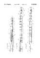
- FIG. 1-AA schematic elevational view of a conveyor belt support structure showing a tail roller in its preadvanced position and separate discrete conveyor belt stands collapsed together adjacent to a fixed permanent conveyor support;
- FIG. 1-Ba schematic elevational view of a conveyor belt support structure of the type shown in FIG. 1-A showing the tail roller of FIG. 1-A advanced and with the separate discrete conveyor belt stands advanced toward the tail roller and separated;
- FIG. 1-Ca schematic elevational view of the advanced tail roller shown in FIG. 1-B with the stands collapsed towards the tail roller and with a permanent structure inserted in the area vacated by collapsing the separate discrete conveyor belt stands;
- FIG. 2-Aa schematic elevational view of a typical separate discrete conveyor belt support stand showing a front elevational view of the stand supported in a continuous discrete moveable floor-supported support structure;
- FIG. 2-Ba schematic side elevational view of a separate discrete conveyor belt support stand resting on a continuous discrete moveable floor-supported support structure;
- FIG. 3a schematic elevational view of a pair of separate discrete conveyor belt support stands shown in the collapsed position resting on a continuous discrete moveable floor-supported support structure;
- FIG. 4a schematic side elevational view of a pair of separate discrete conveyor belt support stands in their extended maximum predetermined distance from each other and connected by chains and resting on the continuous discrete moveable floor-supported support structure;
- FIG. 5a schematic side elevational view of a separate discrete conveyor belt support stand adjacent to a tail piece structure and coupled to the tail piece structure which is pinned to the continuous discrete moveable floor-supported support structure.
- FIGS. 1-A through Cshow a conveyor belt 2.
- a number of separate discrete conveyor belt support stands 4have all necessary rollers 6 and 6' which support the conveyor belt 2.
- all of the separate discrete conveyor belt support stands 4are shown in the collapsed position except for three which are in the extended position in a transition area required to accommodate elevation and profile constraints at a tail roller 8.
- the separate discrete conveyor belt support stands 4are always supported and rest on a continuous discrete moveable floor-supported support structure 10.
- This continuous discrete moveable floor-supported support structure 10has a length at least as long as any desired belt extension which is to be placed in the conveyor belt 2 plus any lineal storage of the collapsed group of stands 4 such as that shown in FIG. 1-A.
- the separate discrete conveyor belt support stands 4are supported by wheels 12 on the continuous discrete moveable floor-supported support structure 10. These wheels 12 permit the separate discrete conveyor belt support stands 4 to move relative to the continuous discrete moveable floor-supported support structure 10.
- the continuous discrete moveable floor-supported support structure 10is supported from a mine floor 14 by skids 16.
- a separate discrete conveyor belt support stand 4is coupled to the tail roller 8 structure by linkage 18.
- Linkage 19couples a separate discrete conveyor belt support stand 4 to a typical permanent belt support 24.
- the tail roller 8 structureis supported by skids 20 which are pinned by pin 22 to the continuous discrete moveable floor-supported support structure 10.
- FIG. 1-AThe structure depicted schematically in FIG. 1-A shows the equipment when a mining machine (not shown) reaches the end of a cut cycle. At that point the mining equipment has to be advanced and the conveyor must be moved towards the new cutting position.
- all of the separate discrete conveyor belt support stands 4are collapsed together except those that are used to form a transition in the belt elevation or profile which are shown as the three separate discrete conveyor belt support stands 4 that are between the tail roller 8 structure and the collapsed stands 4 shown. All of the separate discrete conveyor belt support stands 4 as shown are collapsed against each other with the belt 2 supported by typical permanent belt support 24. This support 24 can be referred to as a permanent or existing fixed belt support structure.
- each separate discrete conveyor belt support stand 4has two chains 26 connected on either side of the belt path to an adjacent separate discrete conveyor belt support stand 4.
- the spacing of the separate discrete conveyor belt support stands 4is set by the length of chains 26 joining the belt support stands 4.
- An additional length of belt 2is added to the line of belt 2 in an amount equal to twice the distance that the tail roller 8 has been advanced from the typical permanent belt support 24.
- FIG. 1-Cshows the insertion of additional fixed belt support structure 28.
- the additional fixed belt support structure 28is added during scheduled down time or other non-mining time.
- the support stands 4are collapsed towards the tail roller 8 and the additional fixed belt support structure 28 is inserted in the area vacated by collapsing the support stands 4 toward the tail roller 8.
- the support stands 4are collapsed against adjoining stands 4 either manually or by means of a mechanical or hydraulic pulling mechanism. Because the stands 4 remain close to the belt insertion area, the belt 2 is supported to facilitate installation of the additional fixed belt support structure 28.
- the linkage 19is removed from the permanent belt support 24 shown in FIG. 1-B and then is reconnected to this additional fixed belt support structure 28 shown in FIG. 1-C.
- the structure shown in FIG. 1-Cis the beginning of a new cut cycle and the process shown in FIGS. 1-A through 1-C is repeated.
- FIGS. 2-A and 2-Bshow schematic arrangements of the separate discrete conveyor belt support stands 4 which have wheels 12 which are carried by the continuous discrete moveable floor-supported support structure 10 which is supported by skids 16.
- the continuous discrete moveable floor-supported support structurehas its skids 16 resting on the mine floor 14.
- the continuous discrete moveable floor-supported support structure 10has channels 30 into which wheels 12 are guided and engaged. All of the necessary belt rollers 6 and 6' for carrying the belt 2 to the tail roller 8 and for returning the belt 2 and supporting it on the return are shown.
- FIG. 3shows two separate discrete conveyor belt support stands 4 adjacent to each other in the collapsed position in which the chain 26 is resting between them.
- the length of chain 26determines the maximum distance that the support stands 4 can be separated.
- FIG. 4shows two separate discrete conveyor belt support stands 4 in the separated position which are separated to their maximum distance in which the chain 26 bears horizontal load but no vertical load.
- FIG. 5shows the linkage 18 connecting one of the belt support stands 4 with the tail roller 8 structure.
- the FIG. 5also shows the pin linkage 22 which connects the support for the tail roller 8 to the continuous discrete moveable floor-supported support structure 10.
- the nonvertical load-bearing connectorssuch as chains 26 permit separation of adjacent stands 4 to a maximum predetermined distance, and the connectors never exceed the height of the support stands 4. This is very important because other types of support stands may have the connecting mechanism higher than the support stand for the belt at some point when the stands are collapsed or extended. This is a disadvantage when working in very tight height constraints in an underground mining operation.
- the belt support stands of the other prior proposalsrest on the mine floor; this causes unevenness and is more time consuming to set up the system.
- the standsrest on the single support which is pulled forward with a tail roller, it is more efficient, easier to handle, and provides a better support setup.
- the systemhas a number of advantages. There are no manual functions required when advancing the tail roller. There are no delays incurred to insert or remove rollers when stands are deployed or collapsed.
- the standsroll on wheels on a support structure which minimizes the force required to distribute or gather the stands.
- the standsnever leave the support structure so that leveling is simplified and there are no concerns related to the stand's support setting on or being dragged through soft, irregular mine floor conditions.
- This systemalso permits retreat of the stands when necessary and simplifies that operation as well.
- Belt height and profile transitionis pre-established and requires no removal or re-assembly during each belt advance.
- Roller spacing of the temporary supportis variable to match that of any fixed belt structure by simply addressing the length of the chains between the support stands.
- the systemis low-maintenance with no complicated linkages to maintain in hostile underground mining conditions.
Landscapes
- Engineering & Computer Science (AREA)
- Mechanical Engineering (AREA)
- Structure Of Belt Conveyors (AREA)
Abstract
Description
Claims (7)
Priority Applications (3)
| Application Number | Priority Date | Filing Date | Title |
|---|---|---|---|
| US08/799,232US5938004A (en) | 1997-02-14 | 1997-02-14 | Method of providing temporary support for an extended conveyor belt |
| ZA981033AZA981033B (en) | 1997-02-14 | 1998-02-09 | Method fo providing temporary support for an extended conveyor belt |
| AU53899/98AAU733818B2 (en) | 1997-02-14 | 1998-02-12 | Method of providing temporary support for an extended conveyor belt |
Applications Claiming Priority (1)
| Application Number | Priority Date | Filing Date | Title |
|---|---|---|---|
| US08/799,232US5938004A (en) | 1997-02-14 | 1997-02-14 | Method of providing temporary support for an extended conveyor belt |
Publications (1)
| Publication Number | Publication Date |
|---|---|
| US5938004Atrue US5938004A (en) | 1999-08-17 |
Family
ID=25175371
Family Applications (1)
| Application Number | Title | Priority Date | Filing Date |
|---|---|---|---|
| US08/799,232Expired - Fee RelatedUS5938004A (en) | 1997-02-14 | 1997-02-14 | Method of providing temporary support for an extended conveyor belt |
Country Status (3)
| Country | Link |
|---|---|
| US (1) | US5938004A (en) |
| AU (1) | AU733818B2 (en) |
| ZA (1) | ZA981033B (en) |
Cited By (51)
| Publication number | Priority date | Publication date | Assignee | Title |
|---|---|---|---|---|
| US6095320A (en)* | 1998-08-26 | 2000-08-01 | Prairie Machine & Parts Mfg., Ltd. | Conveyor deployment system |
| US20020189801A1 (en)* | 2001-01-30 | 2002-12-19 | Cdx Gas, L.L.C., A Texas Limited Liability Company | Method and system for accessing a subterranean zone from a limited surface area |
| US20030201151A1 (en)* | 2002-04-30 | 2003-10-30 | Joy Mm Delaware, Inc. | Mine conveying system |
| US6659269B1 (en) | 1999-08-13 | 2003-12-09 | Consol Engergy Inc. | Apparatus and method for temporary support and isolation for a conveyor belt |
| US20040007389A1 (en)* | 2002-07-12 | 2004-01-15 | Zupanick Joseph A | Wellbore sealing system and method |
| US20040007352A1 (en)* | 2002-07-12 | 2004-01-15 | Zupanick Joseph A | Ramping well bores |
| US20040007351A1 (en)* | 2002-07-12 | 2004-01-15 | Zupanick Joseph A. | Undulating well bore |
| US20040007390A1 (en)* | 2002-07-12 | 2004-01-15 | Zupanick Joseph A. | Wellbore plug system and method |
| US20040114857A1 (en)* | 2002-03-21 | 2004-06-17 | Lianshan Yan | Tunable pulse width generation of return-to-zero format for system optimization |
| US20040124069A1 (en)* | 2002-12-27 | 2004-07-01 | Benjamin Colin William | Telescoping conveyor system |
| US20040178045A1 (en)* | 2003-01-23 | 2004-09-16 | Conner Robert B. | Extendible beltline system |
| US20040182682A1 (en)* | 2003-03-18 | 2004-09-23 | Chadwick Harold Glenn | Extendable and retractable conveyor |
| US6848508B2 (en) | 2001-10-30 | 2005-02-01 | Cdx Gas, Llc | Slant entry well system and method |
| US6942030B2 (en) | 2002-09-12 | 2005-09-13 | Cdx Gas, Llc | Three-dimensional well system for accessing subterranean zones |
| US6964308B1 (en) | 2002-10-08 | 2005-11-15 | Cdx Gas, Llc | Method of drilling lateral wellbores from a slant well without utilizing a whipstock |
| US6964298B2 (en) | 1998-11-20 | 2005-11-15 | Cdx Gas, Llc | Method and system for accessing subterranean deposits from the surface |
| US6976533B2 (en) | 1998-11-20 | 2005-12-20 | Cdx Gas, Llc | Method and system for accessing subterranean deposits from the surface |
| US6988548B2 (en) | 2002-10-03 | 2006-01-24 | Cdx Gas, Llc | Method and system for removing fluid from a subterranean zone using an enlarged cavity |
| US7025154B2 (en) | 1998-11-20 | 2006-04-11 | Cdx Gas, Llc | Method and system for circulating fluid in a well system |
| US7073595B2 (en) | 2002-09-12 | 2006-07-11 | Cdx Gas, Llc | Method and system for controlling pressure in a dual well system |
| US7100687B2 (en) | 2003-11-17 | 2006-09-05 | Cdx Gas, Llc | Multi-purpose well bores and method for accessing a subterranean zone from the surface |
| US7134494B2 (en) | 2003-06-05 | 2006-11-14 | Cdx Gas, Llc | Method and system for recirculating fluid in a well system |
| US7163063B2 (en) | 2003-11-26 | 2007-01-16 | Cdx Gas, Llc | Method and system for extraction of resources from a subterranean well bore |
| US7207390B1 (en) | 2004-02-05 | 2007-04-24 | Cdx Gas, Llc | Method and system for lining multilateral wells |
| US7207395B2 (en) | 2004-01-30 | 2007-04-24 | Cdx Gas, Llc | Method and system for testing a partially formed hydrocarbon well for evaluation and well planning refinement |
| US7222670B2 (en) | 2004-02-27 | 2007-05-29 | Cdx Gas, Llc | System and method for multiple wells from a common surface location |
| US7264048B2 (en) | 2003-04-21 | 2007-09-04 | Cdx Gas, Llc | Slot cavity |
| US7299864B2 (en) | 2004-12-22 | 2007-11-27 | Cdx Gas, Llc | Adjustable window liner |
| US20080035453A1 (en)* | 2006-08-08 | 2008-02-14 | Mark Haustein | Telescoping conveyor with powered and steerable discharge section |
| US20080067033A1 (en)* | 2006-09-14 | 2008-03-20 | Voest-Alpine Materials Handling Gmbh & Co. Kg. | Conveyor |
| US7353877B2 (en) | 2004-12-21 | 2008-04-08 | Cdx Gas, Llc | Accessing subterranean resources by formation collapse |
| US7360595B2 (en) | 2002-05-08 | 2008-04-22 | Cdx Gas, Llc | Method and system for underground treatment of materials |
| US7373984B2 (en) | 2004-12-22 | 2008-05-20 | Cdx Gas, Llc | Lining well bore junctions |
| US7419223B2 (en) | 2003-11-26 | 2008-09-02 | Cdx Gas, Llc | System and method for enhancing permeability of a subterranean zone at a horizontal well bore |
| US7571771B2 (en) | 2005-05-31 | 2009-08-11 | Cdx Gas, Llc | Cavity well system |
| US20100018835A1 (en)* | 2005-06-06 | 2010-01-28 | Metso Minerals (Tampere) Oy | Belt Conveyor And Processing Apparatus |
| US20100276260A1 (en)* | 2009-04-30 | 2010-11-04 | Joy Mm Delaware, Inc. | Mobile machine in main conveyor and method of using such machine |
| US20100276258A1 (en)* | 2007-12-11 | 2010-11-04 | John Bremhorst | Belt Conveyors and Mining |
| CN102459037A (en)* | 2009-05-14 | 2012-05-16 | Fl史密斯公司 | Flsmidth rahco inc |
| US8291974B2 (en) | 1998-11-20 | 2012-10-23 | Vitruvian Exploration, Llc | Method and system for accessing subterranean deposits from the surface and tools therefor |
| US8333245B2 (en) | 2002-09-17 | 2012-12-18 | Vitruvian Exploration, Llc | Accelerated production of gas from a subterranean zone |
| US8376052B2 (en) | 1998-11-20 | 2013-02-19 | Vitruvian Exploration, Llc | Method and system for surface production of gas from a subterranean zone |
| US20130199899A1 (en)* | 2010-10-07 | 2013-08-08 | Hochland Se | Belt conveyor having a variable-length belt support |
| WO2015160535A1 (en)* | 2014-04-14 | 2015-10-22 | Gordon Gordon | Monorail conveyor belt advance and structure installation system for underground mining |
| US20190387690A1 (en)* | 2017-01-26 | 2019-12-26 | Erfgoed Nederland B.V. | Conveyor system for plant containers and method of use |
| JP2020172375A (en)* | 2019-04-11 | 2020-10-22 | 日建リース工業株式会社 | Stretchable conveyor frame mechanism, tail piece carriage system and extension belt conveyor |
| AU2016203614B2 (en)* | 2015-06-02 | 2021-07-01 | Continental Global Material Handling Llc | Conveyor bridge |
| WO2021226659A1 (en)* | 2020-05-11 | 2021-11-18 | Anglo American Metallurgical Coal Pty Ltd | Extendable bootend |
| CN113928820A (en)* | 2021-10-19 | 2022-01-14 | 宁夏天地西北煤机有限公司 | Telescopic device, telescopic machine body and belt type conveying system |
| US11440739B2 (en)* | 2020-03-16 | 2022-09-13 | Superior Industries, Inc. | Portable belt conveyor system, methods and apparatus |
| CN115593878A (en)* | 2022-12-14 | 2023-01-13 | 太重集团向明智能装备股份有限公司(Cn) | Side-supporting self-moving tail for tunneling working face |
Citations (15)
| Publication number | Priority date | Publication date | Assignee | Title |
|---|---|---|---|---|
| DE28915C (en)* | SALZWERK HEILBRONN in Heilbronn | Iron expansion for underwater shafts | ||
| US1576910A (en)* | 1925-02-18 | 1926-03-16 | Hudson William Walter | Loader conveyer |
| US2774462A (en)* | 1955-09-01 | 1956-12-18 | Consolidation Coal Co | Spooled ribbon supported extensible belt conveyor |
| US2808145A (en)* | 1955-12-06 | 1957-10-01 | Goodman Mfg Co | Extensible belt conveyors |
| US2992723A (en)* | 1957-11-22 | 1961-07-18 | Consolidation Coal Co | Extensible belt conveyor |
| US3158253A (en)* | 1963-04-16 | 1964-11-24 | Goodman Mfg Co | Movable roller supports for extensible belt conveyor |
| US3228516A (en)* | 1963-03-27 | 1966-01-11 | Robert T Sheehau | Extensible telescoping belt conveyor |
| US3586154A (en)* | 1969-01-16 | 1971-06-22 | William G Schultz | Extensible conveyor |
| US4245738A (en)* | 1978-04-15 | 1981-01-20 | Dowty Meco Limited | Belt conveyors and belt supporting stools therefor |
| US4260053A (en)* | 1979-10-09 | 1981-04-07 | Hirosuke Onodera | Flexible conveyor belt |
| GB2167372A (en)* | 1984-11-23 | 1986-05-29 | Someral P H B | Conveyors and gantries |
| US4860878A (en)* | 1988-04-26 | 1989-08-29 | D M Enterprises Inc. | Collapsible conveyor support structure/carrier |
| US5181600A (en)* | 1989-01-24 | 1993-01-26 | Chappell Ian C | Conveyor structure |
| AU2837692A (en)* | 1991-11-14 | 1993-05-20 | Meco Australia Pty Limited | Conveyor belt/cutting head advance mechanism |
| US5421449A (en)* | 1991-09-13 | 1995-06-06 | Huwood International Limited | Angle station |
- 1997
- 1997-02-14USUS08/799,232patent/US5938004A/ennot_activeExpired - Fee Related
- 1998
- 1998-02-09ZAZA981033Apatent/ZA981033B/enunknown
- 1998-02-12AUAU53899/98Apatent/AU733818B2/ennot_activeCeased
Patent Citations (15)
| Publication number | Priority date | Publication date | Assignee | Title |
|---|---|---|---|---|
| DE28915C (en)* | SALZWERK HEILBRONN in Heilbronn | Iron expansion for underwater shafts | ||
| US1576910A (en)* | 1925-02-18 | 1926-03-16 | Hudson William Walter | Loader conveyer |
| US2774462A (en)* | 1955-09-01 | 1956-12-18 | Consolidation Coal Co | Spooled ribbon supported extensible belt conveyor |
| US2808145A (en)* | 1955-12-06 | 1957-10-01 | Goodman Mfg Co | Extensible belt conveyors |
| US2992723A (en)* | 1957-11-22 | 1961-07-18 | Consolidation Coal Co | Extensible belt conveyor |
| US3228516A (en)* | 1963-03-27 | 1966-01-11 | Robert T Sheehau | Extensible telescoping belt conveyor |
| US3158253A (en)* | 1963-04-16 | 1964-11-24 | Goodman Mfg Co | Movable roller supports for extensible belt conveyor |
| US3586154A (en)* | 1969-01-16 | 1971-06-22 | William G Schultz | Extensible conveyor |
| US4245738A (en)* | 1978-04-15 | 1981-01-20 | Dowty Meco Limited | Belt conveyors and belt supporting stools therefor |
| US4260053A (en)* | 1979-10-09 | 1981-04-07 | Hirosuke Onodera | Flexible conveyor belt |
| GB2167372A (en)* | 1984-11-23 | 1986-05-29 | Someral P H B | Conveyors and gantries |
| US4860878A (en)* | 1988-04-26 | 1989-08-29 | D M Enterprises Inc. | Collapsible conveyor support structure/carrier |
| US5181600A (en)* | 1989-01-24 | 1993-01-26 | Chappell Ian C | Conveyor structure |
| US5421449A (en)* | 1991-09-13 | 1995-06-06 | Huwood International Limited | Angle station |
| AU2837692A (en)* | 1991-11-14 | 1993-05-20 | Meco Australia Pty Limited | Conveyor belt/cutting head advance mechanism |
Non-Patent Citations (8)
| Title |
|---|
| "Huwood International `Extensible Conveyor` Brochure" believed produced Sep., 1994. |
| "MECO International Introducing `The Trelcon` (Matchappel) Conveyor Structure" (Brochure) date unknown. |
| "MECO International-MECO McCallum Conveyors Matchappel `Quick-Set` Folding Conveyor Structure" date unknown brochure. |
| Huwood International Extensible Conveyor Brochure believed produced Sep., 1994.* |
| MECO International Introducing The Trelcon (Matchappel) Conveyor Structure (Brochure) date unknown.* |
| MECO International MECO McCallum Conveyors Matchappel Quick Set Folding Conveyor Structure date unknown brochure.* |
| World Mining Equipment pp. 32 33, Mar. 1993.* |
| World Mining Equipment pp. 32-33, Mar. 1993. |
Cited By (88)
| Publication number | Priority date | Publication date | Assignee | Title |
|---|---|---|---|---|
| US6095320A (en)* | 1998-08-26 | 2000-08-01 | Prairie Machine & Parts Mfg., Ltd. | Conveyor deployment system |
| US8376052B2 (en) | 1998-11-20 | 2013-02-19 | Vitruvian Exploration, Llc | Method and system for surface production of gas from a subterranean zone |
| US8297350B2 (en) | 1998-11-20 | 2012-10-30 | Vitruvian Exploration, Llc | Method and system for accessing subterranean deposits from the surface |
| US7025154B2 (en) | 1998-11-20 | 2006-04-11 | Cdx Gas, Llc | Method and system for circulating fluid in a well system |
| US9551209B2 (en) | 1998-11-20 | 2017-01-24 | Effective Exploration, LLC | System and method for accessing subterranean deposits |
| US8291974B2 (en) | 1998-11-20 | 2012-10-23 | Vitruvian Exploration, Llc | Method and system for accessing subterranean deposits from the surface and tools therefor |
| US8511372B2 (en) | 1998-11-20 | 2013-08-20 | Vitruvian Exploration, Llc | Method and system for accessing subterranean deposits from the surface |
| US8505620B2 (en) | 1998-11-20 | 2013-08-13 | Vitruvian Exploration, Llc | Method and system for accessing subterranean deposits from the surface and tools therefor |
| US8479812B2 (en) | 1998-11-20 | 2013-07-09 | Vitruvian Exploration, Llc | Method and system for accessing subterranean deposits from the surface and tools therefor |
| US8297377B2 (en) | 1998-11-20 | 2012-10-30 | Vitruvian Exploration, Llc | Method and system for accessing subterranean deposits from the surface and tools therefor |
| US6976533B2 (en) | 1998-11-20 | 2005-12-20 | Cdx Gas, Llc | Method and system for accessing subterranean deposits from the surface |
| US8469119B2 (en) | 1998-11-20 | 2013-06-25 | Vitruvian Exploration, Llc | Method and system for accessing subterranean deposits from the surface and tools therefor |
| US8464784B2 (en) | 1998-11-20 | 2013-06-18 | Vitruvian Exploration, Llc | Method and system for accessing subterranean deposits from the surface and tools therefor |
| US6964298B2 (en) | 1998-11-20 | 2005-11-15 | Cdx Gas, Llc | Method and system for accessing subterranean deposits from the surface |
| US8434568B2 (en) | 1998-11-20 | 2013-05-07 | Vitruvian Exploration, Llc | Method and system for circulating fluid in a well system |
| US8813840B2 (en) | 1998-11-20 | 2014-08-26 | Efective Exploration, LLC | Method and system for accessing subterranean deposits from the surface and tools therefor |
| US8376039B2 (en) | 1998-11-20 | 2013-02-19 | Vitruvian Exploration, Llc | Method and system for accessing subterranean deposits from the surface and tools therefor |
| US8371399B2 (en) | 1998-11-20 | 2013-02-12 | Vitruvian Exploration, Llc | Method and system for accessing subterranean deposits from the surface and tools therefor |
| US8316966B2 (en) | 1998-11-20 | 2012-11-27 | Vitruvian Exploration, Llc | Method and system for accessing subterranean deposits from the surface and tools therefor |
| US6659269B1 (en) | 1999-08-13 | 2003-12-09 | Consol Engergy Inc. | Apparatus and method for temporary support and isolation for a conveyor belt |
| US6986388B2 (en) | 2001-01-30 | 2006-01-17 | Cdx Gas, Llc | Method and system for accessing a subterranean zone from a limited surface area |
| US20020189801A1 (en)* | 2001-01-30 | 2002-12-19 | Cdx Gas, L.L.C., A Texas Limited Liability Company | Method and system for accessing a subterranean zone from a limited surface area |
| US6848508B2 (en) | 2001-10-30 | 2005-02-01 | Cdx Gas, Llc | Slant entry well system and method |
| US7048049B2 (en) | 2001-10-30 | 2006-05-23 | Cdx Gas, Llc | Slant entry well system and method |
| US20040114857A1 (en)* | 2002-03-21 | 2004-06-17 | Lianshan Yan | Tunable pulse width generation of return-to-zero format for system optimization |
| US20030201151A1 (en)* | 2002-04-30 | 2003-10-30 | Joy Mm Delaware, Inc. | Mine conveying system |
| US6729464B2 (en)* | 2002-04-30 | 2004-05-04 | Joy Mm Delaware, Inc. | Mine conveying system |
| AU2003204714B2 (en)* | 2002-04-30 | 2008-02-14 | Joy Global Underground Mining Llc | Mine Conveying System |
| US7360595B2 (en) | 2002-05-08 | 2008-04-22 | Cdx Gas, Llc | Method and system for underground treatment of materials |
| US6991047B2 (en) | 2002-07-12 | 2006-01-31 | Cdx Gas, Llc | Wellbore sealing system and method |
| US20040007389A1 (en)* | 2002-07-12 | 2004-01-15 | Zupanick Joseph A | Wellbore sealing system and method |
| US6725922B2 (en) | 2002-07-12 | 2004-04-27 | Cdx Gas, Llc | Ramping well bores |
| US6991048B2 (en) | 2002-07-12 | 2006-01-31 | Cdx Gas, Llc | Wellbore plug system and method |
| US20040007351A1 (en)* | 2002-07-12 | 2004-01-15 | Zupanick Joseph A. | Undulating well bore |
| US20040007390A1 (en)* | 2002-07-12 | 2004-01-15 | Zupanick Joseph A. | Wellbore plug system and method |
| US20040007352A1 (en)* | 2002-07-12 | 2004-01-15 | Zupanick Joseph A | Ramping well bores |
| US7090009B2 (en) | 2002-09-12 | 2006-08-15 | Cdx Gas, Llc | Three-dimensional well system for accessing subterranean zones |
| US6942030B2 (en) | 2002-09-12 | 2005-09-13 | Cdx Gas, Llc | Three-dimensional well system for accessing subterranean zones |
| US7025137B2 (en) | 2002-09-12 | 2006-04-11 | Cdx Gas, Llc | Three-dimensional well system for accessing subterranean zones |
| US7073595B2 (en) | 2002-09-12 | 2006-07-11 | Cdx Gas, Llc | Method and system for controlling pressure in a dual well system |
| US8333245B2 (en) | 2002-09-17 | 2012-12-18 | Vitruvian Exploration, Llc | Accelerated production of gas from a subterranean zone |
| US6988548B2 (en) | 2002-10-03 | 2006-01-24 | Cdx Gas, Llc | Method and system for removing fluid from a subterranean zone using an enlarged cavity |
| US6964308B1 (en) | 2002-10-08 | 2005-11-15 | Cdx Gas, Llc | Method of drilling lateral wellbores from a slant well without utilizing a whipstock |
| US6758326B1 (en)* | 2002-12-27 | 2004-07-06 | Colin William Benjamin | Telescoping conveyor system |
| US20040124069A1 (en)* | 2002-12-27 | 2004-07-01 | Benjamin Colin William | Telescoping conveyor system |
| WO2004065268A3 (en)* | 2003-01-23 | 2005-02-17 | Jr Robert B Conner | Extendible beltline system |
| US20040178045A1 (en)* | 2003-01-23 | 2004-09-16 | Conner Robert B. | Extendible beltline system |
| US20040182682A1 (en)* | 2003-03-18 | 2004-09-23 | Chadwick Harold Glenn | Extendable and retractable conveyor |
| US7264048B2 (en) | 2003-04-21 | 2007-09-04 | Cdx Gas, Llc | Slot cavity |
| US7134494B2 (en) | 2003-06-05 | 2006-11-14 | Cdx Gas, Llc | Method and system for recirculating fluid in a well system |
| US7100687B2 (en) | 2003-11-17 | 2006-09-05 | Cdx Gas, Llc | Multi-purpose well bores and method for accessing a subterranean zone from the surface |
| US7419223B2 (en) | 2003-11-26 | 2008-09-02 | Cdx Gas, Llc | System and method for enhancing permeability of a subterranean zone at a horizontal well bore |
| US7163063B2 (en) | 2003-11-26 | 2007-01-16 | Cdx Gas, Llc | Method and system for extraction of resources from a subterranean well bore |
| US7207395B2 (en) | 2004-01-30 | 2007-04-24 | Cdx Gas, Llc | Method and system for testing a partially formed hydrocarbon well for evaluation and well planning refinement |
| US7207390B1 (en) | 2004-02-05 | 2007-04-24 | Cdx Gas, Llc | Method and system for lining multilateral wells |
| US7222670B2 (en) | 2004-02-27 | 2007-05-29 | Cdx Gas, Llc | System and method for multiple wells from a common surface location |
| US7353877B2 (en) | 2004-12-21 | 2008-04-08 | Cdx Gas, Llc | Accessing subterranean resources by formation collapse |
| US7373984B2 (en) | 2004-12-22 | 2008-05-20 | Cdx Gas, Llc | Lining well bore junctions |
| US7299864B2 (en) | 2004-12-22 | 2007-11-27 | Cdx Gas, Llc | Adjustable window liner |
| US7571771B2 (en) | 2005-05-31 | 2009-08-11 | Cdx Gas, Llc | Cavity well system |
| US20100018835A1 (en)* | 2005-06-06 | 2010-01-28 | Metso Minerals (Tampere) Oy | Belt Conveyor And Processing Apparatus |
| US7823715B2 (en)* | 2005-06-06 | 2010-11-02 | Metso Minerals Inc. | Belt conveyor and processing apparatus |
| US20080035453A1 (en)* | 2006-08-08 | 2008-02-14 | Mark Haustein | Telescoping conveyor with powered and steerable discharge section |
| US7416075B2 (en)* | 2006-08-08 | 2008-08-26 | Northstar Industries, Inc. | Telescoping conveyor with powered and steerable discharge section |
| US7658271B2 (en)* | 2006-09-14 | 2010-02-09 | Sandvik Mining And Construction G.M.B.H. | Conveyor |
| US20080067033A1 (en)* | 2006-09-14 | 2008-03-20 | Voest-Alpine Materials Handling Gmbh & Co. Kg. | Conveyor |
| US20100276258A1 (en)* | 2007-12-11 | 2010-11-04 | John Bremhorst | Belt Conveyors and Mining |
| US8151968B2 (en)* | 2007-12-11 | 2012-04-10 | John Bremhorst | Belt conveyors and mining |
| US8393456B2 (en)* | 2009-04-30 | 2013-03-12 | Joy Mm Delaware, Inc. | Mobile machine in main conveyor and method of using such machine |
| US20100276260A1 (en)* | 2009-04-30 | 2010-11-04 | Joy Mm Delaware, Inc. | Mobile machine in main conveyor and method of using such machine |
| CN102459037A (en)* | 2009-05-14 | 2012-05-16 | Fl史密斯公司 | Flsmidth rahco inc |
| CN102459037B (en)* | 2009-05-14 | 2014-04-09 | Fl史密斯公司 | Conveying device and stacker including conveying device |
| US9056723B2 (en)* | 2010-10-07 | 2015-06-16 | Hochland Se | Belt conveyor having a variable-length belt support |
| US20130199899A1 (en)* | 2010-10-07 | 2013-08-08 | Hochland Se | Belt conveyor having a variable-length belt support |
| WO2015160535A1 (en)* | 2014-04-14 | 2015-10-22 | Gordon Gordon | Monorail conveyor belt advance and structure installation system for underground mining |
| US20160009496A1 (en)* | 2014-04-14 | 2016-01-14 | Gordon Gordon | Monorail Conveyor Belt Advance and Structure Installation System for Underground Mining |
| US9452887B2 (en)* | 2014-04-14 | 2016-09-27 | Gordon Gordon | Monorail conveyor belt advance and structure installation system for underground mining |
| AU2016203614B2 (en)* | 2015-06-02 | 2021-07-01 | Continental Global Material Handling Llc | Conveyor bridge |
| US10827689B2 (en)* | 2017-01-26 | 2020-11-10 | Erfgoed Nederland B.V. | Conveyor system for plant containers and method of use |
| US20190387690A1 (en)* | 2017-01-26 | 2019-12-26 | Erfgoed Nederland B.V. | Conveyor system for plant containers and method of use |
| JP2020172375A (en)* | 2019-04-11 | 2020-10-22 | 日建リース工業株式会社 | Stretchable conveyor frame mechanism, tail piece carriage system and extension belt conveyor |
| JP7326005B2 (en) | 2019-04-11 | 2023-08-15 | 日建リース工業株式会社 | Telescopic Conveyor Frame Mechanism, Tailpiece Carriage System and Stretched Belt Conveyor |
| US11440739B2 (en)* | 2020-03-16 | 2022-09-13 | Superior Industries, Inc. | Portable belt conveyor system, methods and apparatus |
| WO2021226659A1 (en)* | 2020-05-11 | 2021-11-18 | Anglo American Metallurgical Coal Pty Ltd | Extendable bootend |
| CN113928820A (en)* | 2021-10-19 | 2022-01-14 | 宁夏天地西北煤机有限公司 | Telescopic device, telescopic machine body and belt type conveying system |
| CN113928820B (en)* | 2021-10-19 | 2023-10-17 | 宁夏天地西北煤机有限公司 | Telescopic device, telescopic machine body and belt type conveying system |
| CN115593878A (en)* | 2022-12-14 | 2023-01-13 | 太重集团向明智能装备股份有限公司(Cn) | Side-supporting self-moving tail for tunneling working face |
| CN115593878B (en)* | 2022-12-14 | 2023-04-25 | 太重集团向明智能装备股份有限公司 | Side support type self-moving tail for tunneling working face |
Also Published As
| Publication number | Publication date |
|---|---|
| ZA981033B (en) | 1998-08-11 |
| AU733818B2 (en) | 2001-05-24 |
| AU5389998A (en) | 1998-08-20 |
Similar Documents
| Publication | Publication Date | Title |
|---|---|---|
| US5938004A (en) | Method of providing temporary support for an extended conveyor belt | |
| US4474287A (en) | Variable length conveyor assembly | |
| US4312540A (en) | Continuous mining apparatus and method | |
| AU2011101754A4 (en) | A Suspended Rail System | |
| US4065929A (en) | Mine roof support and method in longwall mining of thick mineral seams | |
| EP0157286A1 (en) | Conveyor belt system for a continuous mining machine | |
| DE2621674A1 (en) | PROCESS AND DEVICE FOR DRIVING AND EXPANSION OF A UNDERGROUND TRAIL AND STRUCTURAL STRUCTURE TO EXERCISE THE PROCEDURE | |
| CA2912446C (en) | Discharging of material excavated in underground workings | |
| US8899692B2 (en) | Method and apparatus for mining a material in an underground environment | |
| AU2004216593B2 (en) | Combination panline and utility drilling or bolting unit | |
| US5979642A (en) | Extendable modular conveyor assembly | |
| EP0795680B1 (en) | Shortwall mining equipment for extraction of pillars in underground coal mines | |
| EP0025307A1 (en) | Apparatus for and a method of erecting an underground roadway support | |
| US10428650B2 (en) | Launch platform for high wall mining | |
| US3471201A (en) | Mineral mining arrangement including track for a mining machine | |
| US3812681A (en) | Mine roof supports | |
| AU570725B2 (en) | Circular heading machine | |
| DE2933766C2 (en) | Partial section tunneling machine | |
| CN120211789B (en) | Bad geological tunnel shield type shield machine and supporting method thereof | |
| DE2651474C3 (en) | Use of a partial section tunneling machine for building through (re-tearing) deformed routes in underground mining | |
| US20090039695A1 (en) | Guide frame for guiding conveyor segments in high wall mining | |
| CH377300A (en) | Auxiliary support for drifting, especially in underground mining | |
| DE2461251B2 (en) | DEVICE FOR PRE-ASSEMBLY, TRANSPORT AND INSTALLATION OF A TRACK OR TUNNEL EXPANSION | |
| US3712071A (en) | Method and apparatus for forming subterranean structures | |
| AU709348B2 (en) | Extendable Modular Conveyor Assembly |
Legal Events
| Date | Code | Title | Description |
|---|---|---|---|
| AS | Assignment | Owner name:CONSOL, INC., PENNSYLVANIA Free format text:ASSIGNMENT OF ASSIGNORS INTEREST;ASSIGNORS:ROBERTS, MARGARET A.;TONKIN, DAVID C.;REEL/FRAME:008487/0955 Effective date:19970206 | |
| AS | Assignment | Owner name:CONSOL ENERGY INC., PENNSYLVANIA Free format text:MERGER;ASSIGNOR:CONSOL INC.;REEL/FRAME:012059/0544 Effective date:20001212 | |
| FPAY | Fee payment | Year of fee payment:4 | |
| AS | Assignment | Owner name:CITICORP NORTH AMERICA, INC., DELAWARE Free format text:SECURITY AGREEMENT;ASSIGNOR:CONSOL ENERGY INC.;REEL/FRAME:014662/0700 Effective date:20030915 | |
| AS | Assignment | Owner name:WILMINGTON TRUST COMPANY, DELAWARE Free format text:SECURITY AGREEMENT;ASSIGNORS:CONSOL ENERGY INC.;CENTRAL OHIO COAL COMPANY;CHURCH STREET HOLDINGS, INC.;AND OTHERS;REEL/FRAME:014815/0586 Effective date:20040630 | |
| AS | Assignment | Owner name:WILMINGTON TRUST COMPANY, DELAWARE Free format text:SECURITY INTEREST;ASSIGNORS:CONSOL ENERGY INC.;CENTRAL OHIO COAL COMPANY;CHURCH STREET HOLDINGS, INC.;AND OTHERS;REEL/FRAME:016610/0723 Effective date:20050808 | |
| FPAY | Fee payment | Year of fee payment:8 | |
| AS | Assignment | Owner name:WILMINGTON TRUST COMPANY, DELAWARE Free format text:SECURITY AGREEMENT;ASSIGNORS:CONSOL ENERGY INC.;CNX MARINE TERMINALS INC.;CONSOL OF CANADA INC.;AND OTHERS;REEL/FRAME:019501/0773 Effective date:20070627 | |
| REMI | Maintenance fee reminder mailed | ||
| AS | Assignment | Owner name:PNC BANK, PENNSYLVANIA Free format text:SECURITY AGREEMENT;ASSIGNOR:WILMINGTON TRUST COMPANY;REEL/FRAME:026124/0018 Effective date:20110412 | |
| LAPS | Lapse for failure to pay maintenance fees | ||
| STCH | Information on status: patent discontinuation | Free format text:PATENT EXPIRED DUE TO NONPAYMENT OF MAINTENANCE FEES UNDER 37 CFR 1.362 | |
| FP | Lapsed due to failure to pay maintenance fee | Effective date:20110817 | |
| AS | Assignment | Owner name:CONSOL ENERGY INC, PENNSYLVANIA Free format text:RELEASE BY SECURED PARTY;ASSIGNOR:CITICORP NORTH AMERICA, INC;REEL/FRAME:035588/0552 Effective date:20141029 | |
| AS | Assignment | Owner name:CONSOL ENERGY INC., PENNSYLVANIA Free format text:RELEASE BY SECURED PARTY;ASSIGNOR:CITICORP NORTH AMERICA, INC.;REEL/FRAME:035659/0395 Effective date:20141029 |