US5937535A - Dryer assembly for curing substrates - Google Patents
Dryer assembly for curing substratesDownload PDFInfo
- Publication number
- US5937535A US5937535AUS08/732,516US73251696AUS5937535AUS 5937535 AUS5937535 AUS 5937535AUS 73251696 AUS73251696 AUS 73251696AUS 5937535 AUS5937535 AUS 5937535A
- Authority
- US
- United States
- Prior art keywords
- dryer
- air
- housing
- sensor
- substrates
- Prior art date
- Legal status (The legal status is an assumption and is not a legal conclusion. Google has not performed a legal analysis and makes no representation as to the accuracy of the status listed.)
- Expired - Fee Related
Links
- 239000000758substrateSubstances0.000titleclaimsabstractdescription35
- 238000012544monitoring processMethods0.000claimsabstractdescription3
- 238000001816coolingMethods0.000claimsdescription15
- 238000010438heat treatmentMethods0.000claimsdescription14
- 238000010926purgeMethods0.000claimsdescription13
- 239000004753textileSubstances0.000abstractdescription22
- 239000003570airSubstances0.000description61
- 239000000976inkSubstances0.000description10
- 238000007639printingMethods0.000description10
- 238000000034methodMethods0.000description7
- 229920001944PlastisolPolymers0.000description6
- 239000004999plastisolSubstances0.000description6
- 238000001035dryingMethods0.000description4
- 239000003086colorantSubstances0.000description3
- 230000008569processEffects0.000description3
- 238000007650screen-printingMethods0.000description3
- 229910001220stainless steelInorganic materials0.000description3
- 239000010935stainless steelSubstances0.000description3
- 238000004891communicationMethods0.000description2
- 238000013461designMethods0.000description2
- 239000000463materialSubstances0.000description2
- 230000007246mechanismEffects0.000description2
- 239000002184metalSubstances0.000description2
- XLYOFNOQVPJJNP-UHFFFAOYSA-NwaterSubstancesOXLYOFNOQVPJJNP-UHFFFAOYSA-N0.000description2
- 239000004809TeflonSubstances0.000description1
- 229920006362Teflon®Polymers0.000description1
- 238000004378air conditioningMethods0.000description1
- 239000012080ambient airSubstances0.000description1
- 230000009286beneficial effectEffects0.000description1
- 238000010276constructionMethods0.000description1
- 238000005336crackingMethods0.000description1
- 238000010586diagramMethods0.000description1
- 230000000694effectsEffects0.000description1
- 230000007613environmental effectEffects0.000description1
- 238000004519manufacturing processMethods0.000description1
- 238000012986modificationMethods0.000description1
- 230000004048modificationEffects0.000description1
- 230000000717retained effectEffects0.000description1
- 238000012216screeningMethods0.000description1
- 238000000859sublimationMethods0.000description1
- 230000008022sublimationEffects0.000description1
- 239000002699waste materialSubstances0.000description1
Images


Classifications
- F—MECHANICAL ENGINEERING; LIGHTING; HEATING; WEAPONS; BLASTING
- F26—DRYING
- F26B—DRYING SOLID MATERIALS OR OBJECTS BY REMOVING LIQUID THEREFROM
- F26B13/00—Machines and apparatus for drying fabrics, fibres, yarns, or other materials in long lengths, with progressive movement
- F26B13/10—Arrangements for feeding, heating or supporting materials; Controlling movement, tension or position of materials
- F26B13/101—Supporting materials without tension, e.g. on or between foraminous belts
- F—MECHANICAL ENGINEERING; LIGHTING; HEATING; WEAPONS; BLASTING
- F26—DRYING
- F26B—DRYING SOLID MATERIALS OR OBJECTS BY REMOVING LIQUID THEREFROM
- F26B15/00—Machines or apparatus for drying objects with progressive movement; Machines or apparatus with progressive movement for drying batches of material in compact form
- F26B15/10—Machines or apparatus for drying objects with progressive movement; Machines or apparatus with progressive movement for drying batches of material in compact form with movement in a path composed of one or more straight lines, e.g. compound, the movement being in alternate horizontal and vertical directions
- F26B15/12—Machines or apparatus for drying objects with progressive movement; Machines or apparatus with progressive movement for drying batches of material in compact form with movement in a path composed of one or more straight lines, e.g. compound, the movement being in alternate horizontal and vertical directions the lines being all horizontal or slightly inclined
- F26B15/18—Machines or apparatus for drying objects with progressive movement; Machines or apparatus with progressive movement for drying batches of material in compact form with movement in a path composed of one or more straight lines, e.g. compound, the movement being in alternate horizontal and vertical directions the lines being all horizontal or slightly inclined the objects or batches of materials being carried by endless belts
- F—MECHANICAL ENGINEERING; LIGHTING; HEATING; WEAPONS; BLASTING
- F26—DRYING
- F26B—DRYING SOLID MATERIALS OR OBJECTS BY REMOVING LIQUID THEREFROM
- F26B21/00—Arrangements or duct systems, e.g. in combination with pallet boxes, for supplying and controlling air or gases for drying solid materials or objects
- F26B21/06—Controlling, e.g. regulating, parameters of gas supply
- F26B21/08—Humidity
Definitions
- the present inventionrelates generally to an assembly for curing inked textiles and substrates and, more particularly, to a novel dryer containing a cooling section and a plurality of spaced apart infrared sensors and humidistats therein to more aptly monitor the temperature and humidity of the inked product travelling therein.
- Indicia on a textile or substratecan be one or more colors.
- a screen printing machinehas at least one station for each color employed.
- a design incorporating two colorswill have at least two printing stations, one for each color.
- a design employing eight colorswill have at least eight stations.
- Each stationgenerally includes a printing head, which supports a single screen, the ink that is used at that station and a mechanism for applying the ink to the textile.
- Each coloris carried by a single screen.
- the textile to be screenedtravels from printing station to printing station by one of a number of methods, such as a chain or a rigid arm.
- the textileis usually carried by a metal pallet, pallet support, flat bed, or platen.
- Common printing machinesinclude turret, oval and linear.
- a dryerhas two primary components, a conveyor system and a heating system. At present, the drying of a textile or substrate with printing thereon is performed by the operator first setting the temperature inside the dryer and setting the speed of the conveyor system. Commonly known mechanisms may be employed to determine/read the ambient temperature somewhere in the dryer, permitting the operator to adjust the conveyor speed to compensate for temperatures too high or too low.
- inksare available in the industry from many different producers. Such inks include water base, sublimation and plastisol.
- the inkis cured or gelled on the textile or substrate to a critical temperature.
- the temperature during the curing processmust be kept within a window suitable for the ink-curing conditions, typically between 125° F. to 450° F.
- temperaturesare crucial.
- the quality and lifetime of a productmay be negatively affected by incorrect temperatures.
- the temperaturemust reach 320° F.; the time for this heating can be less relevant. However, in a range (below 320° F.
- the plastisolwill not properly set, resulting in cracking, or it may become liquified. For example, if the temperature is too low, the plastisol will not cure properly, and will not adhere to the textile/substrate; if the temperature exceeds 350° F., the plastisol will over-gel. Similarly, if a dye in the textile is overheated, it will migrate. And, the textile or substrate may scorch or burn, thereby ruining the product and increasing waste and production costs.
- an apparatus and methodfor drying substrates and/or textiles.
- a dryer for curing substrates or textiles with printings thereonis disclosed.
- the systemincludes, generally, a heating section, a cooling section, a plurality of infrared-based heat temperature sensors and a plurality of humidity sensors.
- a dryer housinghaving an entrance and an exit, means therein for heating the substrates within the dryer housing, and a conveyor system for moving the substrates from the entrance to the exit, includes a plurality of temperature sensors within the dryer housing longitudinally spaced apart between the entrance and exit. These sensors are each infrared-based and placed in a sensor housing projecting into the dryer housing. The sensors themselves have an internal air purging system for cooling the sensor.
- the sensor housinghas a separate external air purging system comprised of an annular chamber formed between an inner chamber wall and an outer chamber wall and two air-lines carrying air into and out of the annular chamber.
- the inner chamber wallis a tubular wall (cylindrical) having a first diameter and the outer chamber wall is a tubular wall (rectangular) having a second diameter, the first diameter being less than the second diameter.
- Both tubular wallsare secured at one end to the dryer housing and are open to the inside of the dryer housing at the other, distal end.
- the inner chamber wall and external chamber wallare concentric tubular walls secured at one end to the top wall of the dryer housing and are open to the inside of the dryer housing at the other, distal end.
- the physical sensoris contained within the inner tubular wall.
- An air-line carrying air into the annular chamberis connected at the one end of each of the tubular walls adjacent the dryer's top wall. And, a second air-line is connected at the same end of the tubular walls removing air from the annular chamber. These air-lines are annularly spaced apart. The air-lines and chamber walls are adapted to pass air from the first air-line and the annular chamber over the opening in the tubular walls and the sensor and back into the annular chamber and into the second air-line.
- dehumidifying meansare provided for removing moisture from any air entering the heating elements of the dryer. This dehumidifying means further cools the substrates within the dryer before they are touched by workers.
- a heat exchangerreceives the dehumidified air and preheats this air directed to the burner assembly by air exhausting from the dryer.
- Humidity detectorsare also provided for monitoring the moisture of the dehumidified air.
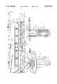
- FIG. 1is a side perspective view of a dryer assembly made in accordance with the teachings of the present invention
- FIG. 2is a sectional view of the dryer assembly along line 2--2 in FIG. 1;
- FIG. 3is a sectional view along line 3--3 in FIG. 1;
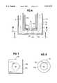
- FIG. 4is a perspective detail of the sensor housing
- FIG. 5is a sectional view along line 5--5 in FIG. 4;
- FIG. 6is a larger sectional view of the lower portion of the sectional view shown in FIG. 5;
- FIG. 7is a sectional view along line 7--7 in FIG. 6;
- FIG. 8is a sectional view along line 8--8 in FIG. 6;
- FIG. 9is a sectional view of the sensor.
- FIG. 10is a schematic flow diagram of the system.
- the assemblyincludes a dryer housing 11 wherein the products passing therethrough are heated.
- the housing 11is formed of opposed side walls 12, opposed end walls 13, a top wall 14 and a bottom wall 15. Such walls are generally constructed of sheet metal and with a double wall to keep the outer wall cool.
- a conveyor system 20(here a looped belt with a plurality of aperture therein (as a screen)) is driven by a motor (not shown) and passes through the housing 11 between the side 12, top 14 and bottom 15 walls from the entrance 16 to the exit 17.
- the ductwork for the systemis generally shown at reference number 25.
- a cooling/dehumidifying/chilling section 100is also added.
- the conveyor 20 shownis totally retained within the dryer housing 11. Some conveyors extend beyond these openings to points outside the housing (shown in phantom (reference number 21 in FIG. 1).
- Heater elementsare within (generally below the conveyor 20) or immediately adjacent the dryer housing 11.
- An intake blower and an in-line blowerare positioned within or adjacent the housing.
- Ducts(represented by duct openings 26) bring the air into the dryer housing 11 above the conveyor 20.
- blowersThere are generally two blowers employed. One blower draws fresh atmospheric air into the system to mix with the gas and burn, and the second blower moves the heated air into the heating area above the conveyor.
- the first zone(preheating zone) is just after the inlet 16 and in the vicinity of the separate infrared preheater 18 (FIG. 3).
- the second zoneis in the vicinity of the first opening 26 for the heated air.
- the third zoneis in the vicinity of the second opening 26 for the heated air.
- the fourth zoneis in the chilling section (shown in phantom at 100).
- a plurality of overlapping heating air knives 27(with slits therein) (FIG. 2) are disposed between the conveyor 20 and the duct openings 26 to the intake blowers and the heating elements 22 for ensuring consistent airflow and velocity to and across the entire width of the conveyor 20. As a result, heated, forced air is blown across the conveyor 20 and any products thereon.
- a plurality of inclined deflectors 28are located below the conveyor 20 for directing the air passing through the housing 11 and conveyor 20 to exhaust ducts (represented by duct openings 29).
- An exhaust bloweris connected to the exhaust ducts 29 to transport the exhaust air to either a stack 30 for release into the surrounding atmosphere or back into the system 10 to recirculate the heated air and increase the assembly's efficiency.
- a circulation blower and blower filter screensare also employed.
- the systemis also insulated to ensure safe use thereof.
- thermometersthat measure the ambient air within the housing. This information is fed to the control panel 31 and displayed and assists an operator in deciding whether to manually adjust the conveyor's speed, the heat applied, and/or the air movement (cubic feet per minute--"CFM").
- this procedureis expanded upon in five (5) respects.
- the temperatureis measured in several locations along the conveyor.
- the temperature measuredis not the ambient temperature of the surrounding environment, but rather the actual temperature of the product (textile/substrate) and/or ink thereon passing through the dryer housing on the conveyor.
- the moisture content of the airis monitored in the system.
- a chilling/dehumidifying systemis incorporated into the dryer assembly.
- the decision process by the operatoris modified.
- sensor housings 50there are a plurality of longitudinally (along the conveyor) spaced apart sensor housings 50 between the entrance 16 and the exit 17 of the dryer assembly 10. These sensor housings 50 each hold a sensor 60 therein, and the sensor housings; project from the top wall 14 of the dryer housing 11 in a direction towards the conveyor 20.
- the sensor housings 50each are comprised of concentric tubular members 55,58.
- tubularone means generally hollow with an outer shell, e.g., cylindrical, rectangular, square, etc.
- the sensor housing 50is rectangular (square) 58 on the outside and cylindrical 55 on the inside.
- a first, outer sensor housing 58is rectangular square) in shape having a second diameter or width D2 (FIG. 5).
- This housing 58is composed of stainless steel and has an outwardly projecting flange 59 at one end for attaching it to the top wall 14 of the dryer housing 11. At the other end, there is an inwardly directed flange 58a with an opening therein 58b. This is shown in detail in FIGS. 6-8.
- a second, inner sensor housing 55is cylindrical in shape and has a first diameter D1 (FIG. 5). The second diameter or width D2 is greater than the first diameter D1.
- This second, inner sensor housing 55is also composed of stainless steel and has an outwardly projecting flange 56 at one end for attaching it to the top wall 14 of the dryer housing 11 or the flange 59 of the outer housing 58.
- the openings 55b,58b in the inwardly directed flanges 55a,58aare aligned with the opening 68 in the physical sensor unit 60.
- annular chamber 70is thus formed in the annular space between the inner sensor housing wall 55 and the outer sensor housing wall 58.
- the inner sensor housinghas a diameter of 1.51" (approximate) and a length of approximately 8"
- the outer sensor housinghas a width of 2.495" and a length of between 7.4" and 7.9"(approximate).
- a first air-line 71 for carrying air into the annular chamber 70is connected to and in communication with the annular chamber at the one end wherein the inner and outer sensor housings 55,58 are connected to the top wall 14 of the dryer 11.
- a second air-line 72 for carrying air out of the annular chamber 70is connected to and in communication with the annular chamber at the one end wherein the inner and outer sensor housings are connected to the top wall of the dryer.
- These air-lines 71,72are diametrically opposed to one another. In short, in relation to the inner sensor housing 55, they are immediately outside the inner sensor housing and approximately annularly spaced 180 degrees apart. In this manner, as shown with flow (air) arrows (Air (A)) in FIGS.
- air exiting the first air-line 71enters the annular chamber 70 at a point adjacent the top wall of the dryer and travels longitudinally towards the opening at the other end of the annular chamber.
- the airthen passes over the opening in the first, inner sensor housing 55 and is drawn into the annular channel 70 by the second air-line 72.
- the airnext travels longitudinally within the annular chamber 70 towards the top wall of the dryer and the second air-line 72 acting as a vacuum.
- This second air-line 72draws air in and receives the air and either exhausts it 30 or recirculates it.
- the actual sensor 60is located within the inner sensor housing 55. As shown in FIG. 6, the clearance between the sensor 60 and the inner sensor housing 55 are minimized to prevent the sensor from moving.
- the sensor 60is directed with its opening 68, lens 61 and sensor detector 62 towards the interior of the dryer housing and specifically towards the conveyor 20. In particular, the open end 68 of the sensor 60 rests on the inwardly directed flange 55a (FIG. 8) of the inner sensor housing 55.
- the preferred sensoris infrared-based and calibrated such that it senses the temperature of the textile/substrate and/or the printing (ink or plastisols) thereon as the textile/substrate passes thereunder. As shown in FIG. 3, there are six (6) sensors 60 in the dryer assembly 11. Each detects the temperature of the product passing thereinunder.
- a seventh sensorthough not shown, is positioned adjacent the separate preheater 18 near the inlet 16 of the assembly 10.
- Suitable sensorsare made by Exergen Corporation, 51 Water Street, Watertown, Mass., under Model Nos. IRt/c.5 and IRt/c.10 (Stainless Steel, Lensed Models). These sensors have 5:1 and 10:1 fields of view, respectively, twisted shielded base thermocouple wire, Teflon sheathed rated to 392° F., and are rated up to 212° F. ambient. They further have built in air purging and air cooling capabilities up to 500° F., and have target temperatures of from -50° F. to +1200° F. Model No. IRt/c.5 has a diameter of 1.375" and a length of 3.34". Model No.
- IRt/c.10has a diameter of 1.375" and a length of 3.76".
- a general detail of the sensoris shown in FIG. 9.
- the sensor 60has a first, closed end 63 with openings therein for the air (A) inlet 64, the electrical (E) connection 65 and the mounting holes 66. Standard fasteners can be used to connect this first end 63 to the top wall 14 of the dryer 11 or attached ends of the sensor housings 55,58.
- the sensorcan also be suspended.
- the open end 68 of the sensor 60rests on the inwardly directed flange 55a (FIG. 8) of the inner sensor housing 55.
- An aligned opening 58b in the outer sensor housing 58allows the sensor unit 60 to read the temperature outside the housings 55,58.
- the air (A)is channeled within the sensor unit 60 between the inlet 64, through the sensor, and out the sensor through the opening 68 to cool the sensor detector 62 itself.
- Thisis an internal air purging system for cooling the sensor unit 60 and sensor detector 62.
- the senor 60has a built-in internal air purging system and a separate external air purging system (the airflow through the annular channel). Both purging systems cool the sensor unit.
- the inner and outer sensor housingsfurther physically protect the sensor from the hot air being blown in the dryer.
- each sensormeasures the target surface temperature as opposed to the ambient temperature. This enables a more accurate picture of the dryer's effect on the product.
- each of the sensor's readingscan be transmitted to a control box 31 and a display attached to the dryer.
- a control box 31can adjust the conveyor's speed, the heat applied in each section or zone, and/or the air movement (CFM) in each zone.
- CFMair movement
- the specific selectionswill depend upon the materials being dried and the ink used.
- a software programcan control these variables. In such a program, the materials and parameters (e.g., drying times and temperature ranges) are compared with the temperatures sensed in the various locations and the program adjusts the dryer's conveyor's speed, heat applied, and air movement.
- sensorscan be situated to monitor the products immediately before or after entering the dryer and/or immediately before or after exiting the dryer. Such information is often useful and important to determine the speed in which products are heated (ramp-up time) and cooled (cool-down time).
- the assembly of the present inventionfurther includes humidity sensors.
- humidity sensorscan be placed inside and immediately outside the dryer. These, too, can be housed and spaced apart as the temperature infrared sensors. The preferred positioning of these humidity sensors are in the ducts between the chiller/dehumidifier (110 in FIG. 10) and in the exhaust lines after the heat exchanger (120 in FIG. 10).
- a suitable humidity sensoris Vaisala, Inc., 100 Commerce Way, Woburn, Mass., under Model NoHMM 30C (for high temperature environmental chambers). This sensor has an operating temperature range of -40° F. to +320° F., and is rated up to 212° F. ambient. The sensor has a 12 mm diameter and a 200 mm length. The sensor is a HUMICAP® H-Sensor.
- the air conditioner/chiller/dehumidifier 110can be controlled. Or, the dryer's conveyor's speed, heat applied, and air movement can be further adjusted either manually or automatically.
- the cooling section 100shown generally in FIGS. 1 and 3, is shown schematically in FIG. 10. As mentioned briefly previously, a cooling section 100 is added to the dryer assembly 10. This cooling section 100 is disposed between the heating section and the exit opening 17 to the dryer. In this cooling section, the product passing therethrough is cooled. One of the primary purposes of this section is to cool down the product so that workers removing products from the conveyor and exiting the assembly can handle the product. In prior systems, the products exit the system too hot to touch. Another purpose of the cooling system is to remove moisture from the air entering the assembly 10. The moisture in the air is removed prior to the air being mixed with the gas and burned.
- the cooling section 100includes an air conditioning, dehumidifier or chilling unit 110.
- Air normally fed into the burner from the surrounding atmosphereis first drawn into the air conditioner/dehumidifier/chiller 110 wherein any moisture is drawn from the air.
- the dry airnext passes through a heat exchanger 120 to preheat this dry air. From the heat exchanger 120, the dry air is moved to the burner units 130 wherein it is mixed with gas and burned.
- the blowers 140direct this heated, dry air to the products on the conveyor 150.
- the exhaust airis next exhausted and passed through the heat exchanger 120. This hot, exhaustion heats the dry air from the dehumidifier in the heat exchanger 120. From the heat exchanger 120, the exhaustion is removed from the assembly.
- the dehumidifier 110cools the products on the conveyor 20 passing therethrough from the heated portion (150) of the assembly 10.
- Humidistats or humidity monitors 160controlling the system 100 are located between the dehumidifier 110 and the heat exchanger 120 and just after the heat exchanger 120 on the exhaust side of the exchanger.
- a baffle 170can be included in the system to recirculate the air. This baffle directs exhausting air back to the burner 130 wherein this air is mixed with gas and burned or directs the exhausting air to the heat exchanger 120 as described above. Ducts can be used to transport the air.
Landscapes
- Engineering & Computer Science (AREA)
- Mechanical Engineering (AREA)
- General Engineering & Computer Science (AREA)
- Textile Engineering (AREA)
- Drying Of Solid Materials (AREA)
Abstract
Description
Claims (19)
Priority Applications (1)
| Application Number | Priority Date | Filing Date | Title |
|---|---|---|---|
| US08/732,516US5937535A (en) | 1996-10-15 | 1996-10-15 | Dryer assembly for curing substrates |
Applications Claiming Priority (1)
| Application Number | Priority Date | Filing Date | Title |
|---|---|---|---|
| US08/732,516US5937535A (en) | 1996-10-15 | 1996-10-15 | Dryer assembly for curing substrates |
Publications (1)
| Publication Number | Publication Date |
|---|---|
| US5937535Atrue US5937535A (en) | 1999-08-17 |
Family
ID=24943819
Family Applications (1)
| Application Number | Title | Priority Date | Filing Date |
|---|---|---|---|
| US08/732,516Expired - Fee RelatedUS5937535A (en) | 1996-10-15 | 1996-10-15 | Dryer assembly for curing substrates |
Country Status (1)
| Country | Link |
|---|---|
| US (1) | US5937535A (en) |
Cited By (39)
| Publication number | Priority date | Publication date | Assignee | Title |
|---|---|---|---|---|
| US6125759A (en)* | 1997-11-11 | 2000-10-03 | Oxy-Dry Corporation | Printing press with infrared dryer safety system |
| US6161304A (en)* | 1999-10-05 | 2000-12-19 | M&R Printing Equipment, Inc. | Dryer assembly |
| US6288377B1 (en)* | 1999-09-22 | 2001-09-11 | Ford Global Technologies, Inc. | Varnish oven for manufacturing process |
| WO2002016139A1 (en)* | 2000-08-25 | 2002-02-28 | Howard Demoore | Power saving automatic zoned dryer apparatus and method |
| US6401358B1 (en)* | 1998-02-23 | 2002-06-11 | Advanced Photonics Technologies Ag | Method and device for drying a rapidly conveyed product to be dried, especially for drying printing ink |
| WO2002055946A1 (en)* | 2001-01-12 | 2002-07-18 | Megtec Systems, Inc. | Web dryer with fully integrated regenerative heat source and control thereof |
| US6539645B2 (en)* | 2001-01-09 | 2003-04-01 | Mark Savarese | Drying apparatus and methods |
| US20040033069A1 (en)* | 2001-08-27 | 2004-02-19 | Atkins Mark R. | Compact integrated forced air drying system |
| US20040170413A1 (en)* | 2001-08-27 | 2004-09-02 | Atkins Mark R. | Compact integrated forced air drying system |
| US20040208997A1 (en)* | 2001-07-26 | 2004-10-21 | Arvidson Richard T | Method and apparatus for applying coatings of molten thermoplastic material over closed pore elastomer foam substrates |
| WO2005019741A1 (en)* | 2003-08-15 | 2005-03-03 | Inkwell Products, Inc. | Compact integrated forced air drying system |
| US20050285313A1 (en)* | 2004-06-24 | 2005-12-29 | Ward Phillip D | Gel/cure unit |
| US20060239669A1 (en)* | 2001-08-27 | 2006-10-26 | Mudry Roman J | Compact air drying system |
| US20070193056A1 (en)* | 2006-02-21 | 2007-08-23 | Marius Switalski | Dryer assembly |
| US20070235437A1 (en)* | 2006-04-05 | 2007-10-11 | Klobucar Joseph M | Paint oven monitoring system |
| US7797855B2 (en)* | 2005-08-31 | 2010-09-21 | Tokyo Electron Limited | Heating apparatus, and coating and developing apparatus |
| WO2011042012A1 (en) | 2009-10-06 | 2011-04-14 | Rainer-Maria Schnell | Drier for printing substrates |
| US20110203129A1 (en)* | 2010-02-25 | 2011-08-25 | Krones Ag | Transport - and drying device for individually transported articles and method for drying individually transported articles |
| US20120216417A1 (en)* | 2009-10-23 | 2012-08-30 | Truking Technology Limited | Over Device of Tunnel-Type Sterilization Dryer |
| DE202010017782U1 (en) | 2010-10-06 | 2012-09-11 | Rainer-Maria Schnell | Dryers for substrates |
| US20130000138A1 (en)* | 2011-07-01 | 2013-01-03 | Hon Hai Precision Industry Co., Ltd. | Oven and drying system using the same |
| WO2013025410A1 (en)* | 2011-08-12 | 2013-02-21 | Fluke Corporation | Continuous temperature monitoring in a paint curing oven |
| WO2013093942A3 (en)* | 2011-12-20 | 2013-08-15 | Bry Air [Asia] Pvt.Ltd. | Method and device for moisture determination and control |
| US20140047731A1 (en)* | 2012-08-17 | 2014-02-20 | M&R Printing Equipment, Inc. | Dryer Conveyor Speed Control Apparatus and Method |
| US20140352561A1 (en)* | 2013-05-31 | 2014-12-04 | Joe I.V. Rosenberg | Process and apparatus for conversion of a coldset web printing press to a hybrid heatset and coldset printing press |
| US20150013177A1 (en)* | 2013-07-15 | 2015-01-15 | Finishing Brands Holdings Inc. | Curing System and Method |
| CN104964551A (en)* | 2015-07-12 | 2015-10-07 | 安徽捷迅光电技术有限公司 | Infrared hot air drying device |
| US20170219282A1 (en)* | 2016-01-28 | 2017-08-03 | Fuji Xerox Co., Ltd. | Drying device |
| WO2017196333A1 (en)* | 2016-05-12 | 2017-11-16 | Hewlett-Packard Development Company, L.P. | Cooling airflow for a heating lamp |
| WO2017196331A1 (en)* | 2016-05-12 | 2017-11-16 | Hewlett-Packard Development Company, L.P. | Cooling airflow for a sensor in a lamp assembly |
| US20170360157A1 (en)* | 2016-06-17 | 2017-12-21 | Nike, Inc. | Energy Efficient Infrared Oven With Air Circulation |
| US9939198B2 (en) | 2015-06-26 | 2018-04-10 | M&R Printing Equipment, Inc. | Dryer conveyor belt tracking system |
| US9951991B2 (en) | 2015-08-31 | 2018-04-24 | M&R Printing Equipment, Inc. | System and method for dynamically adjusting dryer belt speed |
| US10011136B2 (en) | 2014-02-13 | 2018-07-03 | Brown Manufacturing Group, Inc. | Ink curing apparatus and method |
| US10113795B2 (en) | 2015-06-26 | 2018-10-30 | M&R Printing Equipment, Inc. | Dryer conveyor belt tracking system |
| WO2020254027A1 (en)* | 2019-06-19 | 2020-12-24 | Lars Engel | System and method for drying hemp |
| US11098449B2 (en)* | 2020-01-03 | 2021-08-24 | Palo Alto Research Center Incorporated | Pre-drier apparatus and method |
| FR3112304A1 (en)* | 2020-07-10 | 2022-01-14 | Exelsius | System for treating an object comprising a material to be crosslinked. |
| CN115451667A (en)* | 2022-09-21 | 2022-12-09 | 安徽省谱诺药化设备有限公司 | Intelligent drying production line |
Citations (2)
| Publication number | Priority date | Publication date | Assignee | Title |
|---|---|---|---|---|
| US4756091A (en)* | 1987-06-25 | 1988-07-12 | Herbert Van Denend | Hybrid high-velocity heated air/infra-red drying oven |
| US4996939A (en)* | 1988-11-03 | 1991-03-05 | D.E.M. Controls Of Canada, Inc. | Apparatus for drying printed circuit boards |
- 1996
- 1996-10-15USUS08/732,516patent/US5937535A/ennot_activeExpired - Fee Related
Patent Citations (2)
| Publication number | Priority date | Publication date | Assignee | Title |
|---|---|---|---|---|
| US4756091A (en)* | 1987-06-25 | 1988-07-12 | Herbert Van Denend | Hybrid high-velocity heated air/infra-red drying oven |
| US4996939A (en)* | 1988-11-03 | 1991-03-05 | D.E.M. Controls Of Canada, Inc. | Apparatus for drying printed circuit boards |
Non-Patent Citations (6)
| Title |
|---|
| "Sprint `S` Modular Textile Gas Dryer" brochure, Mar. 6, 1995. |
| "Sprint Modular Textile Gas Dryer" brochure, Feb. 20, 1995. |
| Exergen brochure and specifications published as least as early as Sep. 1995.* |
| Sprint Modular Textile Gas Dryer brochure, Feb. 20, 1995.* |
| Sprint S Modular Textile Gas Dryer brochure, Mar. 6, 1995.* |
| Vaisala brochure and specifications published at least as early as Sep. 1995.* |
Cited By (63)
| Publication number | Priority date | Publication date | Assignee | Title |
|---|---|---|---|---|
| US6125759A (en)* | 1997-11-11 | 2000-10-03 | Oxy-Dry Corporation | Printing press with infrared dryer safety system |
| US6401358B1 (en)* | 1998-02-23 | 2002-06-11 | Advanced Photonics Technologies Ag | Method and device for drying a rapidly conveyed product to be dried, especially for drying printing ink |
| US6288377B1 (en)* | 1999-09-22 | 2001-09-11 | Ford Global Technologies, Inc. | Varnish oven for manufacturing process |
| US6161304A (en)* | 1999-10-05 | 2000-12-19 | M&R Printing Equipment, Inc. | Dryer assembly |
| US6877247B1 (en) | 2000-08-25 | 2005-04-12 | Demoore Howard W. | Power saving automatic zoned dryer apparatus and method |
| WO2002016139A1 (en)* | 2000-08-25 | 2002-02-28 | Howard Demoore | Power saving automatic zoned dryer apparatus and method |
| US6539645B2 (en)* | 2001-01-09 | 2003-04-01 | Mark Savarese | Drying apparatus and methods |
| US10281211B2 (en) | 2001-01-09 | 2019-05-07 | International Flavors & Fragrances Inc. | Drying apparatus and methods |
| US8984763B2 (en) | 2001-01-09 | 2015-03-24 | Columbia Phyto Technology Llc | Drying apparatus and methods |
| AU2002219933B2 (en)* | 2001-01-12 | 2005-10-06 | Megtec Systems, Inc. | Web dryer with fully integrated regenerative heat source and control thereof |
| US6681497B2 (en) | 2001-01-12 | 2004-01-27 | Megtec Systems, Inc. | Web dryer with fully integrated regenerative heat source and control thereof |
| US6651357B2 (en)* | 2001-01-12 | 2003-11-25 | Megtec Systems, Inc. | Web dryer with fully integrated regenerative heat source and control thereof |
| WO2002055946A1 (en)* | 2001-01-12 | 2002-07-18 | Megtec Systems, Inc. | Web dryer with fully integrated regenerative heat source and control thereof |
| US20040208997A1 (en)* | 2001-07-26 | 2004-10-21 | Arvidson Richard T | Method and apparatus for applying coatings of molten thermoplastic material over closed pore elastomer foam substrates |
| US20040170413A1 (en)* | 2001-08-27 | 2004-09-02 | Atkins Mark R. | Compact integrated forced air drying system |
| US20040033069A1 (en)* | 2001-08-27 | 2004-02-19 | Atkins Mark R. | Compact integrated forced air drying system |
| US6931205B2 (en) | 2001-08-27 | 2005-08-16 | Flexair, Inc. | Compact integrated forced air drying system |
| US7809253B2 (en)* | 2001-08-27 | 2010-10-05 | Flexair, Inc. | Compact air drying system |
| US20060239669A1 (en)* | 2001-08-27 | 2006-10-26 | Mudry Roman J | Compact air drying system |
| US7187856B2 (en)* | 2001-08-27 | 2007-03-06 | Flexair, Inc. | Compact integrated forced air drying system |
| WO2005019741A1 (en)* | 2003-08-15 | 2005-03-03 | Inkwell Products, Inc. | Compact integrated forced air drying system |
| US20050285313A1 (en)* | 2004-06-24 | 2005-12-29 | Ward Phillip D | Gel/cure unit |
| US7797855B2 (en)* | 2005-08-31 | 2010-09-21 | Tokyo Electron Limited | Heating apparatus, and coating and developing apparatus |
| US20070193056A1 (en)* | 2006-02-21 | 2007-08-23 | Marius Switalski | Dryer assembly |
| US20070235437A1 (en)* | 2006-04-05 | 2007-10-11 | Klobucar Joseph M | Paint oven monitoring system |
| WO2011042012A1 (en) | 2009-10-06 | 2011-04-14 | Rainer-Maria Schnell | Drier for printing substrates |
| US20120216417A1 (en)* | 2009-10-23 | 2012-08-30 | Truking Technology Limited | Over Device of Tunnel-Type Sterilization Dryer |
| US8726533B2 (en)* | 2009-10-23 | 2014-05-20 | Truking Technology Limited | Over device of tunnel-type sterilization dryer |
| US20110203129A1 (en)* | 2010-02-25 | 2011-08-25 | Krones Ag | Transport - and drying device for individually transported articles and method for drying individually transported articles |
| US8793901B2 (en)* | 2010-02-25 | 2014-08-05 | Krones Ag | Transport- and drying device for individually transported articles and method for drying individually transported articles |
| DE202010017782U1 (en) | 2010-10-06 | 2012-09-11 | Rainer-Maria Schnell | Dryers for substrates |
| US20130000138A1 (en)* | 2011-07-01 | 2013-01-03 | Hon Hai Precision Industry Co., Ltd. | Oven and drying system using the same |
| WO2013025410A1 (en)* | 2011-08-12 | 2013-02-21 | Fluke Corporation | Continuous temperature monitoring in a paint curing oven |
| WO2013093942A3 (en)* | 2011-12-20 | 2013-08-15 | Bry Air [Asia] Pvt.Ltd. | Method and device for moisture determination and control |
| US9534840B2 (en) | 2011-12-20 | 2017-01-03 | Bry Air (Asia) Pvt. Ltd. | Method and device for moisture determination and control |
| CN104364646A (en)* | 2011-12-20 | 2015-02-18 | 百瑞空气工程(亚洲)有限公司 | Method and device for moisture determination and control |
| CN104364646B (en)* | 2011-12-20 | 2020-06-09 | 百瑞空气工程(亚洲)有限公司 | Method and apparatus for moisture determination and control |
| US20140047731A1 (en)* | 2012-08-17 | 2014-02-20 | M&R Printing Equipment, Inc. | Dryer Conveyor Speed Control Apparatus and Method |
| WO2014194335A3 (en)* | 2013-05-31 | 2015-05-07 | Rosenberg Joe I V | Process and apparatus of a hybrid heatset and coldset printing press |
| US20140352561A1 (en)* | 2013-05-31 | 2014-12-04 | Joe I.V. Rosenberg | Process and apparatus for conversion of a coldset web printing press to a hybrid heatset and coldset printing press |
| US20150013177A1 (en)* | 2013-07-15 | 2015-01-15 | Finishing Brands Holdings Inc. | Curing System and Method |
| US10011136B2 (en) | 2014-02-13 | 2018-07-03 | Brown Manufacturing Group, Inc. | Ink curing apparatus and method |
| US12173963B2 (en) | 2015-06-26 | 2024-12-24 | M&R Printing Equipment, Inc. | Dryer conveyor belt tracking system |
| US11740017B2 (en) | 2015-06-26 | 2023-08-29 | M&R Printing Equipment, Inc. | Dryer conveyor belt tracking system |
| US9939198B2 (en) | 2015-06-26 | 2018-04-10 | M&R Printing Equipment, Inc. | Dryer conveyor belt tracking system |
| US10113795B2 (en) | 2015-06-26 | 2018-10-30 | M&R Printing Equipment, Inc. | Dryer conveyor belt tracking system |
| US20190137176A1 (en)* | 2015-06-26 | 2019-05-09 | M&R Printing Equipment, Inc. | Dryer conveyor belt tracking system |
| US10794631B2 (en)* | 2015-06-26 | 2020-10-06 | M&R Printing Equipment, Inc. | Dryer conveyor belt tracking system |
| US11226156B2 (en) | 2015-06-26 | 2022-01-18 | M&R Printing Equipment, Inc. | Dryer conveyor belt tracking system |
| CN104964551A (en)* | 2015-07-12 | 2015-10-07 | 安徽捷迅光电技术有限公司 | Infrared hot air drying device |
| US9951991B2 (en) | 2015-08-31 | 2018-04-24 | M&R Printing Equipment, Inc. | System and method for dynamically adjusting dryer belt speed |
| US11156401B2 (en) | 2015-08-31 | 2021-10-26 | M&R Printing Equipment, Inc. | System and method for dynamically adjusting dryer belt speed |
| US10612850B2 (en) | 2015-08-31 | 2020-04-07 | M&R Printing Equipment, Inc. | System and method for dynamically adjusting dryer belt speed |
| US10240864B2 (en)* | 2016-01-28 | 2019-03-26 | Fuji Xerox Co., Ltd. | Drying device |
| US20170219282A1 (en)* | 2016-01-28 | 2017-08-03 | Fuji Xerox Co., Ltd. | Drying device |
| WO2017196333A1 (en)* | 2016-05-12 | 2017-11-16 | Hewlett-Packard Development Company, L.P. | Cooling airflow for a heating lamp |
| WO2017196331A1 (en)* | 2016-05-12 | 2017-11-16 | Hewlett-Packard Development Company, L.P. | Cooling airflow for a sensor in a lamp assembly |
| US10791799B2 (en)* | 2016-06-17 | 2020-10-06 | Nike, Inc. | Energy efficient infrared oven with air circulation |
| US20170360157A1 (en)* | 2016-06-17 | 2017-12-21 | Nike, Inc. | Energy Efficient Infrared Oven With Air Circulation |
| WO2020254027A1 (en)* | 2019-06-19 | 2020-12-24 | Lars Engel | System and method for drying hemp |
| US11098449B2 (en)* | 2020-01-03 | 2021-08-24 | Palo Alto Research Center Incorporated | Pre-drier apparatus and method |
| FR3112304A1 (en)* | 2020-07-10 | 2022-01-14 | Exelsius | System for treating an object comprising a material to be crosslinked. |
| CN115451667A (en)* | 2022-09-21 | 2022-12-09 | 安徽省谱诺药化设备有限公司 | Intelligent drying production line |
Similar Documents
| Publication | Publication Date | Title |
|---|---|---|
| US5937535A (en) | Dryer assembly for curing substrates | |
| US20140047731A1 (en) | Dryer Conveyor Speed Control Apparatus and Method | |
| US6161304A (en) | Dryer assembly | |
| US5625962A (en) | Method for measuring the moisture content of a web of goods on a through-flow dryer and device for working the method | |
| US11156401B2 (en) | System and method for dynamically adjusting dryer belt speed | |
| US3744146A (en) | Shrink tunnel | |
| US20170030645A1 (en) | Dryer conveyor belt tracking system | |
| JPS625074A (en) | Infrared drier | |
| NO960205L (en) | Apparatus for drying a web of material | |
| CA2166589C (en) | In-line processing of a heated and reacting continuous sheet of material | |
| CN110494288A (en) | Mostly band and multizone drying textile device | |
| JP4384365B2 (en) | Infrared dryer with air purification shutter | |
| US3758960A (en) | Apparatus for drying materials | |
| CA2342669A1 (en) | Apparatus for continuously drying unpackaged food products, in particular vegetables | |
| GB2102598A (en) | Automatic air flow control system for dryer | |
| JPH01247165A (en) | Drying device for rotary offset press | |
| US8113214B2 (en) | Apparatus for conditioning of organic materials | |
| US3411217A (en) | Method and apparatus for drying printed silk screened articles | |
| US20050086826A1 (en) | Tunnel finisher with infrared feedback temperature control | |
| JPH1163828A (en) | Hot-blast drying furnace | |
| JPS5841431B2 (en) | conveyor belt | |
| US3435757A (en) | Hot melt stenciling method and apparatus | |
| US3071865A (en) | Web dryer | |
| SU1753216A1 (en) | Pasty material drier | |
| GB1451718A (en) | Heat treatment of granulates |
Legal Events
| Date | Code | Title | Description |
|---|---|---|---|
| AS | Assignment | Owner name:M & R PRINTING EQUIPMENT, INC., ILLINOIS Free format text:ASSIGNMENT OF ASSIGNORS INTEREST;ASSIGNORS:HOFFMAN, RICHARD C., JR.;IACCINO, LAURENCE A.;SWITALSKI, MARIUSZ;REEL/FRAME:008310/0942 Effective date:19961122 | |
| AS | Assignment | Owner name:LASALLE NATIONAL BANK, ILLINOIS Free format text:SECURITY INTEREST;ASSIGNOR:M & R PRINTING EQUIPMENT, INC.;REEL/FRAME:008454/0728 Effective date:19970401 | |
| AS | Assignment | Owner name:FIRST SOURCE FINANCIAL LLP, AS AGENT, ILLINOIS Free format text:SECURITY INTEREST;ASSIGNOR:M & R PRINTING EQUIPMENT, INC.;REEL/FRAME:009893/0416 Effective date:19990323 | |
| AS | Assignment | Owner name:M & R PRINTING EQUIPMENT, INC., ILLINOIS Free format text:RELEASE OF INTELLECTUAL PROPERTY SECURITY AGREEMENT;ASSIGNOR:LASALLE NATIONAL BANK;REEL/FRAME:009935/0601 Effective date:19990324 | |
| AS | Assignment | Owner name:M&R PRINTING EQUIPMENT, INC., ILLINOIS Free format text:TERMINATION OF SECURITY INTEREST & RELEASE OF COLLATERAL;ASSIGNOR:FIRST SOURCE FINANCIAL, LLP;REEL/FRAME:013751/0066 Effective date:20001101 | |
| REMI | Maintenance fee reminder mailed | ||
| LAPS | Lapse for failure to pay maintenance fees | ||
| FP | Lapsed due to failure to pay maintenance fee | Effective date:20030817 | |
| STCH | Information on status: patent discontinuation | Free format text:PATENT EXPIRED DUE TO NONPAYMENT OF MAINTENANCE FEES UNDER 37 CFR 1.362 |