US5937055A - Method and apparatus for routing telephone calls between alternate telephone service providers - Google Patents
Method and apparatus for routing telephone calls between alternate telephone service providersDownload PDFInfo
- Publication number
- US5937055A US5937055AUS08/789,571US78957197AUS5937055AUS 5937055 AUS5937055 AUS 5937055AUS 78957197 AUS78957197 AUS 78957197AUS 5937055 AUS5937055 AUS 5937055A
- Authority
- US
- United States
- Prior art keywords
- telephone
- call
- entered
- user
- instrument
- Prior art date
- Legal status (The legal status is an assumption and is not a legal conclusion. Google has not performed a legal analysis and makes no representation as to the accuracy of the status listed.)
- Expired - Lifetime
Links
- 238000000034methodMethods0.000titleclaimsabstractdescription19
- 238000001514detection methodMethods0.000claimsdescription7
- 238000004891communicationMethods0.000claimsdescription5
- 230000005540biological transmissionEffects0.000claims4
- 238000010586diagramMethods0.000description2
- 230000003213activating effectEffects0.000description1
- 230000003044adaptive effectEffects0.000description1
- 238000010276constructionMethods0.000description1
- 230000001419dependent effectEffects0.000description1
- 230000003831deregulationEffects0.000description1
- 230000009977dual effectEffects0.000description1
- 239000000835fiberSubstances0.000description1
- 238000001208nuclear magnetic resonance pulse sequenceMethods0.000description1
- 238000006467substitution reactionMethods0.000description1
Images

Classifications
- H—ELECTRICITY
- H04—ELECTRIC COMMUNICATION TECHNIQUE
- H04Q—SELECTING
- H04Q3/00—Selecting arrangements
- H04Q3/64—Distributing or queueing
- H04Q3/66—Traffic distributors
- H—ELECTRICITY
- H04—ELECTRIC COMMUNICATION TECHNIQUE
- H04M—TELEPHONIC COMMUNICATION
- H04M3/00—Automatic or semi-automatic exchanges
- H04M3/42—Systems providing special services or facilities to subscribers
- H04M3/4228—Systems providing special services or facilities to subscribers in networks
Definitions
- the present inventionis directed to a method and apparatus for enabling a telephone user to select between an available plurality of alternate telephone service providers automatically, as a function of the telephone number dialed.
- the present inventionprovides an automatic switching and path selection device which automatically determines the appropriate routing of a telephone call based upon the digits dialed by the telephone user.
- the inventive deviceis positioned between the telephone instrument and two alternate communication paths such, by way of a nonlimiting example, as the local telephone loop, which carries the user's local telephone calls, and a CATV line which handles the user's long distance ("LD") calls.
- the terms "telephone instrument” or “telephone”are defined as any device for carrying voice and/or data communication signals.
- a telephone callas the term is used herein, may be a voice, data or fax call, or some combination thereof.
- the deviceFor incoming calls, the device senses which of the two incoming lines is ringing, selects between them, and routes the call to the user's telephone, providing ringing current if needed.
- the devicesenses the on-hook or off-hook condition of the telephone, receives the dialed digits from the telephone instrument as the user inputs them or dials and, based on the digits dialed, routes the call appropriately to either the local loop or the LD line.
- the line selection criteriamay for example be based, in one particular contemplated application, upon whether the user dials one of a "1" or a "0" at the beginning of the dialing sequence, which typically indicates that a long distance call is being made.
- the systemmay also be readily adapted to recognize other initial dialing sequences, such as specific access codes or custom calling features, emergency dialing sequences such as 911, information sequences such as 411, etc.
- the devicemay be configured to accept TOUCH TONETM, i.e. Dual Tone Multi Frequency (DTMF) tones, or dial pulses, as required.
- DTMFDual Tone Multi Frequency
- the deviceIn the event of a power failure, the device defaults to the local loop, since most local telephone service providers, are equipped with battery backup and thus continue to provide service during power outages.
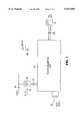
- FIG. 1is a schematic drawing of the route selector unit of the present invention
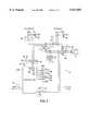
- FIG. 2is a schematic diagram of a preferred switch and control arrangement of the route selector unit of the present invention.
- FIG. 3is a schematic diagram of a preferred arrangement of the controller portion of the present invention.
- a route selector 10in accordance with the present invention, deployed in a preferred arrangement for routing calls between a user's telephone set 12 through inside telephone line 28 and two alternate services for carrying telephone calls.
- the first telephone serviceis provided, for example, by the user's local telephone company via a local loop telephone (telco) line 26, and is utilized for providing local telephone service for handling local telephone calls.
- telcolocal loop telephone
- the term local telephone callis defined as those calls that do not require the dialing of an area code or other dialing prefix.
- the second, or alternate, telephone serviceis provided, for example, by the user's CATV provider via alternate telephone line 21.
- Alternate line 21in turn connects to a CATV interface 20 which splits the signals carried over cable 24 into telephone signals and television signals.
- Television signalsare sent to the user's TV set via TV cable 22, while telephone calls are sent to the route selector 10 by line 21.
- CATV interface 20may be provided by the CATV company or, optionally, may be integrated into the route selector 10.
- the design and implementation of interface 20is a matter of design choice well within the skill of the routineer in the art, and accordingly will not be described in detail herein.
- the route selector 10may also be equipped with an optional battery 30 for supplying power to the unit in the event of a power failure. The operation of the inventive device during power outages is described in further detail hereinbelow. Additionally, although only one telephone 12 is depicted, the apparatus and its operation as herein described are equally applicable where multiple telephone sets or extensions (not shown) are connected to inside line 28.
- FIGS. 2 and 3the major functional components of the route selector 10 are schematically depicted.
- a relay contact point depicted in the drawing figures with an "X"indicates a normally open contact
- a relay contact depicted with an " -- "indicates a normally closed contact.
- Selector 10operates under the control by a central controller 100, preferably managed by a microprocessor 101, although discrete transistor, MOSFET, relay logic, and/or other art-recognized logic and switch control methodology may also be utilized.
- Controller 100provides switch logic, relay control, telephone line sensing, tone generation and other functions further described below.
- relay and switchare used herein interchangeably, and are intended to denote any controllable device capable of opening and closing electrical contact points or completing or breaking electrical circuits, such as, by way of non-limiting example, electromechanical relays, transistors, solenoids, MOSFET switches, and their art-recognized equivalents.
- a relay controller 109under the direction of microprocessor 101, controls all of the relays in the system via a series of relay control leads numbered 140 through 149.
- the design and construction of the necessary circuitry to control the relays of the systemis considered to be well within the level of skill of the routineer in the art and is not accordingly discussed in detail herein.
- Power Failure (PF) relay 41reverts to its default state, with contacts PF1 and PF2 open and contacts PF3 and PF4 closed. For this reason PF relay 41 is preferably implemented as an electromechanical relay. In this state, telephone instrument 12 is directly connected to telephone line 26 and operates as a standard telephone set, powered by the telephone company's central office battery in a manner well known in the art.
- the selector 10may be equipped with an optional battery 30 which permits the selector to operate normally while the optional battery power remains available. Should battery 30 become discharged, then selector 10 reverts to the power failure condition first described above.
- PF relay 41is turned on or activated via relay control lead 141 as soon as power is supplied, thereby closing contacts PF1 and PF2 while contacts PF3 and PF4 open.
- Internal call control relay (CCI) 48is turned on via control lead 148, closing contacts CCI 1 and CCI 2 and thereby connecting telephone 12 to controller 100.
- Hook detector 52connected to controller 100 via lead 55, continuously monitors the status of telephone 12. Hook detector 52 may be a routine circuit which measures current drawn by the telephone 12; this current is typically approximately 20 milliamps or more when the phone is off hook, and generally less than a few microamps when the phone is on hook. The specific method by which hook status is monitored is a matter of simple, art-recognized design choice, and is not critical to the invention.
- Controller 100powers telephone relay (T) 42 via control lead 142, closing contacts T 1 and T 2 , and powers cut through relay (CT) 44 via control lead 144 to thereby close contacts CT 1 and CT 2 . Since, as mentioned above, the PF relay is on while power to selector 10 is on, telco line 26 is directly connected to telephone 12. Telephone 12 rings as a result of the ring current from telco line 26 and, when answered, the call proceeds in a typical manner.
- Controller 100powers cable relay (C) 40 via control lead 140, closing contacts C 1 and C 2 , and powers cut through relay (CT) 44 via control lead 144 to close contacts CT 1 and CT 2 . Since, as mentioned above, the PF relay is on while power to selector 10 is on, alternate line 21 is thus directly connected to telephone 12. Telephone 12 rings as a result of the ring current received from alternate line 21 and, as above, when answered the call proceeds in the typical fashion. In the event that the cable line 26 carries nothing more than an audio telephone signal, CATV interface 20 would then need to provide talk battery, ring current, etc. in a manner well known in the art.
- controller 100When controller 100 receives an off-hook condition signal from hook detector 52, and there is no ring detection signal from either of the ring detectors 50 and 51, controller 100 assumes that an outgoing call is being made. With talk battery 108 already connected to telephone 12, controller 100 sends dial tone to telephone 12 via dial tone source 104. As the user begins to dial, DTMF receiver 102 begins to collect the dialed digits or, if telephone 12 is a dial pulse phone, then pulse detector 110 begins to collect the dialed digits. Operation of the system is essentially the same regardless of whether tone or pulse dialing is used, and for the remainder of this discussion DTMF dialing is assumed.
- microprocessor 101analyzes the dialed digits. If the dialed digits do not begin with either a "0" or "1”, then the microprocessor assumes that the call is a local call and proceeds to route the call to telco line 26.
- controller 100turns on the T relay 42 via control lead 142 to thereby close contacts T 1 and T 2 , turns on the central office (CCO) relay 46 via control lead 146 to thereby close contacts CCO 1 and CCO 2 , and turns on the loop (LP) relay 49 via control lead 149, completing the telephone loop through resistor 56 and thereby simulating an off hook condition across telco line 26.
- Resistor 56is typically 600 ohms, but its exact value may be dependent on the specific line conditions and local loop design; selection of the ideal resistance value is a routine matter of design choice.
- Controller 100attempts to detect a dial tone on telco line 26 via dial tone detector 107 and, assuming one to be present, passes the dialed digits, now generated by DTMF tone generator 103, to telco line 26. After seven digits have been dialed and passed to telco line 26, controller 100 activates cut through (CT) relay 44 via relay control lead 144, and deactivates the LP, CCI and CCO relays, thus connecting the telephone 12 to telco line 26. The call then proceeds in the normal, art-recognized manner. Since the telephone is directly connected to the telco line, further dialing of digits will not affect the selector 10, and the user may accordingly send DTMF tones to control voice mail systems, speech response systems and the like without difficulty.
- CTcut through
- hook detector 52signals controller 100, at which point the T and CT relays are turned off and the CCI relay turned back on, readying the controller for the next call. If the controller 100 does not receive a dial tone on telco line 26, then controller 100 does not pass any digits but instead sends a trk busy signal via trunk busy tone generator 105, thereby indicating to the caller that the call failed for reasons other than a busy condition at the far end.
- the microprocessor 101determines that the first dialed digit is a "0" or a "1"
- the microprocessorassumes that a long distance call is being made and proceeds to route the call to CATV line 21.
- an interdigit timer 111is first activated to wait a preselected time, typically several seconds, after which time, if no further dialed digits are received, the call is routed to telco line 26 as an operator call in a manner of the local call as described above.
- the controller 100turns on the C relay 40 via control lead 140 to close contacts C 1 and C 2 , turns on the central office (CCO) relay 46 via control lead 146 to close contacts CCO 1 and CCO 2 , and turns on the loop (LP) relay 49 via control lead 149, completing the telephone loop to alternate line 21.
- the systemattempts to draw dial tone from the CATV system and, if unsuccessful, sends the trunk busy tone described above. If dial tone is successfully obtained, then call processing continues.
- the interdigit timer 111Since in long distance dialing the number of digits dialed is frequently variable, the interdigit timer 111 remains active for each digit dialed and the dialed digits are buffered by microprocessor 101.
- the controllersends dialed digits generated by DTMF source 103 over alternate line 21 one at a time, holding at least one and optionally more dialed digits in reserve as a general matter of design choice.
- the controller 100sends whatever digits have remained buffered over alternate line 21, and then connects telephone 12 to alternate line 21 by activating cut through (CT) relay 44 and deactivating the LP, CCI and CCO relays. The call then proceeds in the normal manner described above.
- CTcut through
- microprocessor 101can be programmed to analyze the digits dialed and route calls containing certain area codes or dialing prefixes or other dialing sequences to one or the other (or still another) phone line or service provider, depending upon and as a matter of selectable user preference.
- Preferential area codesmay be stored, for example in microprocessor memory 200, for comparison by microprocessor 101 with the digits actually dialed.
- in-state or in-region callsmay be routed to the local telco while out of state or out of region calls are automatically routed to an alternate carrier.
- system of the present inventionmay be configured or programmed to recognize certain predetermined dialing prefixes which will force the line selection, such for example, as “#1" for local loop calls and "#2" for alternate calls.
- controller 100may be programmed to recognize "999" or another sequence as the "#” key, and a different dial pulse sequence for the "*" key on a DTMF keyboard, as appropriate or required.
- inventive controllermay be programmed to recognize predefined digit sequences such as 911, 411, 611, and other special short codes as fully-designated calls which should be passed to the local loop without having the interdigit timer 111 wait for .additional digits.
- Interdigit timer 111may also be constructed or configured so as to be adaptive, whereby it will automatically adjust the interdigit wait period in accordance with the speed at which the user generally dials, or when an automatic dialer is used in conjunction with telephone 12.
- the various tones generated by the system of the present inventionmay be generated using any of a variety of suitable methods well within the knowledge of those skilled in the art such, by way of non-limiting example, as a Digital Signal Processor (DSP) with a digital to analog (D/A) converter, discrete circuits, or other art-recognized equivalents.
- DSPDigital Signal Processor
- D/Adigital to analog
- tone detectionmay be performed by a typical DTMF receiver chip, DSP, or other art recognized equivalent.
- the call routing system of the present inventionmay be expanded to select between more than two alternative or complimentary service providers by adding the necessary additional relays and programming the microprocessor 101 accordingly.
Landscapes
- Engineering & Computer Science (AREA)
- Computer Networks & Wireless Communication (AREA)
- Telephonic Communication Services (AREA)
Abstract
Description
Claims (24)
Priority Applications (1)
| Application Number | Priority Date | Filing Date | Title |
|---|---|---|---|
| US08/789,571US5937055A (en) | 1997-01-28 | 1997-01-28 | Method and apparatus for routing telephone calls between alternate telephone service providers |
Applications Claiming Priority (1)
| Application Number | Priority Date | Filing Date | Title |
|---|---|---|---|
| US08/789,571US5937055A (en) | 1997-01-28 | 1997-01-28 | Method and apparatus for routing telephone calls between alternate telephone service providers |
Publications (1)
| Publication Number | Publication Date |
|---|---|
| US5937055Atrue US5937055A (en) | 1999-08-10 |
Family
ID=25148027
Family Applications (1)
| Application Number | Title | Priority Date | Filing Date |
|---|---|---|---|
| US08/789,571Expired - LifetimeUS5937055A (en) | 1997-01-28 | 1997-01-28 | Method and apparatus for routing telephone calls between alternate telephone service providers |
Country Status (1)
| Country | Link |
|---|---|
| US (1) | US5937055A (en) |
Cited By (21)
| Publication number | Priority date | Publication date | Assignee | Title |
|---|---|---|---|---|
| US20020176018A1 (en)* | 2001-05-25 | 2002-11-28 | White David Edward | Variable message format transmission protocol, enabled on cable television networks as a bypass of physical local telephone exchange carrier networks for long distance telecommunications services |
| US20040036625A1 (en)* | 1998-07-13 | 2004-02-26 | Hitachi Ltd. | Remote keyless entry system |
| US20040136514A1 (en)* | 2003-01-09 | 2004-07-15 | Darwin Rambo | Method and system for 7-digit dialing in 10 digit mandatory dialing areas |
| US20050117732A1 (en)* | 2002-01-25 | 2005-06-02 | Claude Arpin | Automatic telephone line switch |
| US7023979B1 (en) | 2002-03-07 | 2006-04-04 | Wai Wu | Telephony control system with intelligent call routing |
| US7274688B2 (en) | 2000-04-18 | 2007-09-25 | Serconet Ltd. | Telephone communication system over a single telephone line |
| US20080065428A1 (en)* | 2006-09-07 | 2008-03-13 | Tyler Duffy | Automated Campground System |
| US7436842B2 (en) | 2001-10-11 | 2008-10-14 | Serconet Ltd. | Outlet with analog signal adapter, a method for use thereof and a network using said outlet |
| US7522714B2 (en) | 2000-03-20 | 2009-04-21 | Serconet Ltd. | Telephone outlet for implementing a local area network over telephone lines and a local area network using such outlets |
| US7542554B2 (en) | 2001-07-05 | 2009-06-02 | Serconet, Ltd | Telephone outlet with packet telephony adapter, and a network using same |
| US7656904B2 (en) | 2003-03-13 | 2010-02-02 | Mosaid Technologies Incorporated | Telephone system having multiple distinct sources and accessories therefor |
| US7676034B1 (en) | 2003-03-07 | 2010-03-09 | Wai Wu | Method and system for matching entities in an auction |
| US7873058B2 (en) | 2004-11-08 | 2011-01-18 | Mosaid Technologies Incorporated | Outlet with analog signal adapter, a method for use thereof and a network using said outlet |
| US7894595B1 (en) | 2002-03-07 | 2011-02-22 | Wai Wu | Telephony control system with intelligent call routing |
| US7916858B1 (en) | 2001-06-25 | 2011-03-29 | Toby Heller | Agent training sensitive call routing system |
| US8300798B1 (en) | 2006-04-03 | 2012-10-30 | Wai Wu | Intelligent communication routing system and method |
| US8325636B2 (en) | 1998-07-28 | 2012-12-04 | Mosaid Technologies Incorporated | Local area network of serial intelligent cells |
| US10567975B2 (en) | 2005-10-04 | 2020-02-18 | Hoffberg Family Trust 2 | Multifactorial optimization system and method |
| US10718031B1 (en) | 2014-11-03 | 2020-07-21 | Wai Wu | Method and system for matching entities in an auction |
| US10943273B2 (en) | 2003-02-05 | 2021-03-09 | The Hoffberg Family Trust 2004-1 | System and method for determining contingent relevance |
| US10986164B2 (en) | 2004-01-13 | 2021-04-20 | May Patents Ltd. | Information device |
Citations (13)
| Publication number | Priority date | Publication date | Assignee | Title |
|---|---|---|---|---|
| US4555594A (en)* | 1983-08-03 | 1985-11-26 | At&T Bell Laboratories | Telephone interexchange signaling protocol |
| US4565903A (en)* | 1983-08-03 | 1986-01-21 | At&T Bell Laboratories | Telephone interexchange carrier selection |
| US4577066A (en)* | 1983-08-03 | 1986-03-18 | At&T Bell Laboratories | Telephone interexchange call routing |
| US4866763A (en)* | 1988-08-17 | 1989-09-12 | American Telephone And Telegraph Company, At&T Bell Laboratories | Interexchange carrier automatic route selection system |
| US5309504A (en)* | 1991-11-18 | 1994-05-03 | Syntellect Acquisition Corp. | Automated identification of attendant positions in a telecommunication system |
| US5309505A (en)* | 1991-05-20 | 1994-05-03 | Inventions, Inc. | Automated voice system for improving agent efficiency and improving service to parties on hold |
| US5341415A (en)* | 1992-09-22 | 1994-08-23 | Paul Baran | Method and apparatus for sharing of common in-house wiring to permit multiple telephone carriers to serve the same customer |
| US5422945A (en)* | 1993-07-16 | 1995-06-06 | American Express Trs | Fast last digit detection of a dialed telephone number |
| US5515427A (en)* | 1994-07-19 | 1996-05-07 | At&T Corp. | Completion of intelligent network telephone calls |
| US5550910A (en)* | 1994-11-18 | 1996-08-27 | Lucent Technologies Inc. | End-User communications device with automatic carrier selection capability for intraLATA toll calls |
| US5563939A (en)* | 1993-12-09 | 1996-10-08 | At&T | Method and system for delivering a communication service |
| US5563938A (en)* | 1995-04-07 | 1996-10-08 | Teltone Corporation | Subscriber telephone diverter switch |
| US5655014A (en)* | 1994-02-18 | 1997-08-05 | Aurora Systems, Inc. | Switching device independent computer-telephone integration system |
- 1997
- 1997-01-28USUS08/789,571patent/US5937055A/ennot_activeExpired - Lifetime
Patent Citations (13)
| Publication number | Priority date | Publication date | Assignee | Title |
|---|---|---|---|---|
| US4555594A (en)* | 1983-08-03 | 1985-11-26 | At&T Bell Laboratories | Telephone interexchange signaling protocol |
| US4565903A (en)* | 1983-08-03 | 1986-01-21 | At&T Bell Laboratories | Telephone interexchange carrier selection |
| US4577066A (en)* | 1983-08-03 | 1986-03-18 | At&T Bell Laboratories | Telephone interexchange call routing |
| US4866763A (en)* | 1988-08-17 | 1989-09-12 | American Telephone And Telegraph Company, At&T Bell Laboratories | Interexchange carrier automatic route selection system |
| US5309505A (en)* | 1991-05-20 | 1994-05-03 | Inventions, Inc. | Automated voice system for improving agent efficiency and improving service to parties on hold |
| US5309504A (en)* | 1991-11-18 | 1994-05-03 | Syntellect Acquisition Corp. | Automated identification of attendant positions in a telecommunication system |
| US5341415A (en)* | 1992-09-22 | 1994-08-23 | Paul Baran | Method and apparatus for sharing of common in-house wiring to permit multiple telephone carriers to serve the same customer |
| US5422945A (en)* | 1993-07-16 | 1995-06-06 | American Express Trs | Fast last digit detection of a dialed telephone number |
| US5563939A (en)* | 1993-12-09 | 1996-10-08 | At&T | Method and system for delivering a communication service |
| US5655014A (en)* | 1994-02-18 | 1997-08-05 | Aurora Systems, Inc. | Switching device independent computer-telephone integration system |
| US5515427A (en)* | 1994-07-19 | 1996-05-07 | At&T Corp. | Completion of intelligent network telephone calls |
| US5550910A (en)* | 1994-11-18 | 1996-08-27 | Lucent Technologies Inc. | End-User communications device with automatic carrier selection capability for intraLATA toll calls |
| US5563938A (en)* | 1995-04-07 | 1996-10-08 | Teltone Corporation | Subscriber telephone diverter switch |
Cited By (64)
| Publication number | Priority date | Publication date | Assignee | Title |
|---|---|---|---|---|
| US20040036625A1 (en)* | 1998-07-13 | 2004-02-26 | Hitachi Ltd. | Remote keyless entry system |
| US8325636B2 (en) | 1998-07-28 | 2012-12-04 | Mosaid Technologies Incorporated | Local area network of serial intelligent cells |
| US8885659B2 (en) | 1998-07-28 | 2014-11-11 | Conversant Intellectual Property Management Incorporated | Local area network of serial intelligent cells |
| US8885660B2 (en) | 1998-07-28 | 2014-11-11 | Conversant Intellectual Property Management Incorporated | Local area network of serial intelligent cells |
| US8867523B2 (en) | 1998-07-28 | 2014-10-21 | Conversant Intellectual Property Management Incorporated | Local area network of serial intelligent cells |
| US8908673B2 (en) | 1998-07-28 | 2014-12-09 | Conversant Intellectual Property Management Incorporated | Local area network of serial intelligent cells |
| US8363797B2 (en) | 2000-03-20 | 2013-01-29 | Mosaid Technologies Incorporated | Telephone outlet for implementing a local area network over telephone lines and a local area network using such outlets |
| US7522714B2 (en) | 2000-03-20 | 2009-04-21 | Serconet Ltd. | Telephone outlet for implementing a local area network over telephone lines and a local area network using such outlets |
| US8855277B2 (en) | 2000-03-20 | 2014-10-07 | Conversant Intellectual Property Managment Incorporated | Telephone outlet for implementing a local area network over telephone lines and a local area network using such outlets |
| US7715534B2 (en) | 2000-03-20 | 2010-05-11 | Mosaid Technologies Incorporated | Telephone outlet for implementing a local area network over telephone lines and a local area network using such outlets |
| US7274688B2 (en) | 2000-04-18 | 2007-09-25 | Serconet Ltd. | Telephone communication system over a single telephone line |
| US7466722B2 (en) | 2000-04-18 | 2008-12-16 | Serconet Ltd | Telephone communication system over a single telephone line |
| US7593394B2 (en) | 2000-04-18 | 2009-09-22 | Mosaid Technologies Incorporated | Telephone communication system over a single telephone line |
| US8223800B2 (en) | 2000-04-18 | 2012-07-17 | Mosaid Technologies Incorporated | Telephone communication system over a single telephone line |
| US7397791B2 (en) | 2000-04-18 | 2008-07-08 | Serconet, Ltd. | Telephone communication system over a single telephone line |
| US8000349B2 (en) | 2000-04-18 | 2011-08-16 | Mosaid Technologies Incorporated | Telephone communication system over a single telephone line |
| US8559422B2 (en) | 2000-04-18 | 2013-10-15 | Mosaid Technologies Incorporated | Telephone communication system over a single telephone line |
| US20020176018A1 (en)* | 2001-05-25 | 2002-11-28 | White David Edward | Variable message format transmission protocol, enabled on cable television networks as a bypass of physical local telephone exchange carrier networks for long distance telecommunications services |
| US8582753B1 (en) | 2001-06-25 | 2013-11-12 | Toby Heller | Agent training sensitive call routing system |
| US7916858B1 (en) | 2001-06-25 | 2011-03-29 | Toby Heller | Agent training sensitive call routing system |
| US8971519B1 (en) | 2001-06-25 | 2015-03-03 | Steven Hoffberg | Agent training sensitive call routing system |
| US9635177B1 (en) | 2001-06-25 | 2017-04-25 | Steven M. Hoffberg | Agent training sensitive call routing system |
| US10447855B1 (en) | 2001-06-25 | 2019-10-15 | Steven M. Hoffberg | Agent training sensitive call routing system |
| US7769030B2 (en) | 2001-07-05 | 2010-08-03 | Mosaid Technologies Incorporated | Telephone outlet with packet telephony adapter, and a network using same |
| US7680255B2 (en) | 2001-07-05 | 2010-03-16 | Mosaid Technologies Incorporated | Telephone outlet with packet telephony adaptor, and a network using same |
| US8761186B2 (en) | 2001-07-05 | 2014-06-24 | Conversant Intellectual Property Management Incorporated | Telephone outlet with packet telephony adapter, and a network using same |
| US8472593B2 (en) | 2001-07-05 | 2013-06-25 | Mosaid Technologies Incorporated | Telephone outlet with packet telephony adaptor, and a network using same |
| US7542554B2 (en) | 2001-07-05 | 2009-06-02 | Serconet, Ltd | Telephone outlet with packet telephony adapter, and a network using same |
| US7453895B2 (en) | 2001-10-11 | 2008-11-18 | Serconet Ltd | Outlet with analog signal adapter, a method for use thereof and a network using said outlet |
| US7436842B2 (en) | 2001-10-11 | 2008-10-14 | Serconet Ltd. | Outlet with analog signal adapter, a method for use thereof and a network using said outlet |
| US7953071B2 (en) | 2001-10-11 | 2011-05-31 | Mosaid Technologies Incorporated | Outlet with analog signal adapter, a method for use thereof and a network using said outlet |
| US7889720B2 (en) | 2001-10-11 | 2011-02-15 | Mosaid Technologies Incorporated | Outlet with analog signal adapter, a method for use thereof and a network using said outlet |
| US7860084B2 (en) | 2001-10-11 | 2010-12-28 | Mosaid Technologies Incorporated | Outlet with analog signal adapter, a method for use thereof and a network using said outlet |
| US20050117732A1 (en)* | 2002-01-25 | 2005-06-02 | Claude Arpin | Automatic telephone line switch |
| US7315615B2 (en)* | 2002-01-25 | 2008-01-01 | Sittelle Technologies, Inc. | Automatic telephone line switch |
| US7269253B1 (en) | 2002-03-07 | 2007-09-11 | Wai Wu | Telephony control system with intelligent call routing |
| US7894595B1 (en) | 2002-03-07 | 2011-02-22 | Wai Wu | Telephony control system with intelligent call routing |
| US9736308B1 (en) | 2002-03-07 | 2017-08-15 | Wai Wu | Intelligent communication routing |
| US8831205B1 (en) | 2002-03-07 | 2014-09-09 | Wai Wu | Intelligent communication routing |
| US10560579B1 (en) | 2002-03-07 | 2020-02-11 | Wai Wu | Intelligent communication routing |
| US7023979B1 (en) | 2002-03-07 | 2006-04-04 | Wai Wu | Telephony control system with intelligent call routing |
| US8077848B2 (en)* | 2003-01-09 | 2011-12-13 | Broadcom Corporation | Method and system for 7-digit dialing in 10 digit mandatory dialing areas |
| US20040136514A1 (en)* | 2003-01-09 | 2004-07-15 | Darwin Rambo | Method and system for 7-digit dialing in 10 digit mandatory dialing areas |
| US11790413B2 (en) | 2003-02-05 | 2023-10-17 | Hoffberg Family Trust 2 | System and method for communication |
| US10943273B2 (en) | 2003-02-05 | 2021-03-09 | The Hoffberg Family Trust 2004-1 | System and method for determining contingent relevance |
| US7676034B1 (en) | 2003-03-07 | 2010-03-09 | Wai Wu | Method and system for matching entities in an auction |
| US9860391B1 (en) | 2003-03-07 | 2018-01-02 | Wai Wu | Method and system for matching entities in an auction |
| US9456086B1 (en) | 2003-03-07 | 2016-09-27 | Wai Wu | Method and system for matching entities in an auction |
| US10237420B1 (en) | 2003-03-07 | 2019-03-19 | Wai Wu | Method and system for matching entities in an auction |
| US7738453B2 (en) | 2003-03-13 | 2010-06-15 | Mosaid Technologies Incorporated | Telephone system having multiple sources and accessories therefor |
| US8238328B2 (en) | 2003-03-13 | 2012-08-07 | Mosaid Technologies Incorporated | Telephone system having multiple distinct sources and accessories therefor |
| US7746905B2 (en) | 2003-03-13 | 2010-06-29 | Mosaid Technologies Incorporated | Private telephone network connected to more than one public network |
| US7656904B2 (en) | 2003-03-13 | 2010-02-02 | Mosaid Technologies Incorporated | Telephone system having multiple distinct sources and accessories therefor |
| US11095708B2 (en) | 2004-01-13 | 2021-08-17 | May Patents Ltd. | Information device |
| US10986164B2 (en) | 2004-01-13 | 2021-04-20 | May Patents Ltd. | Information device |
| US10986165B2 (en) | 2004-01-13 | 2021-04-20 | May Patents Ltd. | Information device |
| US7873058B2 (en) | 2004-11-08 | 2011-01-18 | Mosaid Technologies Incorporated | Outlet with analog signal adapter, a method for use thereof and a network using said outlet |
| USRE49334E1 (en) | 2005-10-04 | 2022-12-13 | Hoffberg Family Trust 2 | Multifactorial optimization system and method |
| US10567975B2 (en) | 2005-10-04 | 2020-02-18 | Hoffberg Family Trust 2 | Multifactorial optimization system and method |
| US9807239B1 (en) | 2006-04-03 | 2017-10-31 | Wai Wu | Intelligent communication routing system and method |
| US10491748B1 (en) | 2006-04-03 | 2019-11-26 | Wai Wu | Intelligent communication routing system and method |
| US8300798B1 (en) | 2006-04-03 | 2012-10-30 | Wai Wu | Intelligent communication routing system and method |
| US20080065428A1 (en)* | 2006-09-07 | 2008-03-13 | Tyler Duffy | Automated Campground System |
| US10718031B1 (en) | 2014-11-03 | 2020-07-21 | Wai Wu | Method and system for matching entities in an auction |
Similar Documents
| Publication | Publication Date | Title |
|---|---|---|
| US5937055A (en) | Method and apparatus for routing telephone calls between alternate telephone service providers | |
| KR940000706B1 (en) | Dialing features for cellular telephone with standard telephone set | |
| US7054417B2 (en) | Advanced call screening appliance | |
| US6031899A (en) | Method and apparatus for identifying type of call | |
| US4937854A (en) | Call screening device | |
| US5590182A (en) | System for interception and transmission of communication signals on telephone and data lines | |
| EP0915608A2 (en) | Call forwarding via a 2-line phone | |
| EP0688126A2 (en) | A voice messaging system | |
| US5369697A (en) | Method and apparatus for automatically switching between pulse code and DTMF signals generated by a telephone | |
| US5781625A (en) | System and apparatus for generating within the premises a dial tone for enhanced phone services | |
| US5898756A (en) | Parallel-connected dialing signal transmission-inhibiting device for data transfer over a telephone link | |
| US6408067B1 (en) | Methods and apparatus for intercepting dual-tone multi-frequency (DTMF) signals and for redialing the intercepted signals with additional DTMF signals | |
| US4523056A (en) | Telephone including resistive array for dialing and system for using such telephone | |
| CA2133682C (en) | Telecommunication system and method enabling a user to get access to automated call processing from a central station operating on pulse-dialling mode | |
| KR970009080A (en) | Automatic telephone dialing device that supports specific carrier identification number | |
| US6230007B1 (en) | Method and apparatus for detecting message waiting signal | |
| US6853725B2 (en) | Method and apparatus for off-hook management of plural subscriber premises devices connected to same telephone line | |
| KR0134721B1 (en) | Direct Call Control Method of Direct Station Subscriber in Switching System | |
| KR20010106506A (en) | Enhanced Call Waiting | |
| US5910985A (en) | Ground start and tip ground detection without the use of -48V or tip bait circuit | |
| KR100190917B1 (en) | Stopper of tube container | |
| KR100421848B1 (en) | Key Phone System Operation | |
| KR100247350B1 (en) | Number outting method in communication device | |
| KR100216399B1 (en) | Notification method of telephone unconnected extension of exchange | |
| KR0132932B1 (en) | Call processing method by voice guidance in key phone system |
Legal Events
| Date | Code | Title | Description |
|---|---|---|---|
| AS | Assignment | Owner name:LUCENT TECHNOLOGIES INC., NEW JERSEY Free format text:ASSIGNMENT OF ASSIGNORS INTEREST;ASSIGNOR:KAPLAN, ALAN EDWARD;REEL/FRAME:008419/0689 Effective date:19970107 | |
| STCF | Information on status: patent grant | Free format text:PATENTED CASE | |
| FEPP | Fee payment procedure | Free format text:PAYOR NUMBER ASSIGNED (ORIGINAL EVENT CODE: ASPN); ENTITY STATUS OF PATENT OWNER: LARGE ENTITY | |
| AS | Assignment | Owner name:THE CHASE MANHATTAN BANK, AS COLLATERAL AGENT, TEX Free format text:CONDITIONAL ASSIGNMENT OF AND SECURITY INTEREST IN PATENT RIGHTS;ASSIGNOR:LUCENT TECHNOLOGIES INC. (DE CORPORATION);REEL/FRAME:011722/0048 Effective date:20010222 | |
| FEPP | Fee payment procedure | Free format text:PAYOR NUMBER ASSIGNED (ORIGINAL EVENT CODE: ASPN); ENTITY STATUS OF PATENT OWNER: LARGE ENTITY Free format text:PAYER NUMBER DE-ASSIGNED (ORIGINAL EVENT CODE: RMPN); ENTITY STATUS OF PATENT OWNER: LARGE ENTITY | |
| FPAY | Fee payment | Year of fee payment:4 | |
| AS | Assignment | Owner name:LUCENT TECHNOLOGIES INC., NEW JERSEY Free format text:TERMINATION AND RELEASE OF SECURITY INTEREST IN PATENT RIGHTS;ASSIGNOR:JPMORGAN CHASE BANK, N.A. (FORMERLY KNOWN AS THE CHASE MANHATTAN BANK), AS ADMINISTRATIVE AGENT;REEL/FRAME:018590/0047 Effective date:20061130 | |
| FPAY | Fee payment | Year of fee payment:8 | |
| FPAY | Fee payment | Year of fee payment:12 |