US5936804A - Impact features on suspensions for improved damage resiliancy in disk drives - Google Patents
Impact features on suspensions for improved damage resiliancy in disk drivesDownload PDFInfo
- Publication number
- US5936804A US5936804AUS08/978,857US97885797AUS5936804AUS 5936804 AUS5936804 AUS 5936804AUS 97885797 AUS97885797 AUS 97885797AUS 5936804 AUS5936804 AUS 5936804A
- Authority
- US
- United States
- Prior art keywords
- load beam
- disk
- slider
- suspension assembly
- impact reducing
- Prior art date
- Legal status (The legal status is an assumption and is not a legal conclusion. Google has not performed a legal analysis and makes no representation as to the accuracy of the status listed.)
- Expired - Fee Related
Links
Images


Classifications
- G—PHYSICS
- G11—INFORMATION STORAGE
- G11B—INFORMATION STORAGE BASED ON RELATIVE MOVEMENT BETWEEN RECORD CARRIER AND TRANSDUCER
- G11B5/00—Recording by magnetisation or demagnetisation of a record carrier; Reproducing by magnetic means; Record carriers therefor
- G11B5/48—Disposition or mounting of heads or head supports relative to record carriers ; arrangements of heads, e.g. for scanning the record carrier to increase the relative speed
- G11B5/4806—Disposition or mounting of heads or head supports relative to record carriers ; arrangements of heads, e.g. for scanning the record carrier to increase the relative speed specially adapted for disk drive assemblies, e.g. assembly prior to operation, hard or flexible disk drives
- G—PHYSICS
- G11—INFORMATION STORAGE
- G11B—INFORMATION STORAGE BASED ON RELATIVE MOVEMENT BETWEEN RECORD CARRIER AND TRANSDUCER
- G11B21/00—Head arrangements not specific to the method of recording or reproducing
- G11B21/16—Supporting the heads; Supporting the sockets for plug-in heads
Definitions
- This inventionrelates generally to a suspension arm assembly for supporting a read/write head carrying slider adjacent to a relatively moving recording medium in a disk drive. More particularly, it relates to a suspension arm assembly that is especially well suited for supporting a slider at an end of a load beam, wherein the load beam includes impact features which limits displacement of the slider from the disk surface.
- a hard disk drive 5conventionally includes at least one rotating data storage disk 45. Frequently, but not necessarily, a plurality of disks 45 is mounted on a common rotating spindle 9 to which rotational force is imparted by a suitable spindle motor 13.
- Each data storage disk 45is provided with an associated transducer carrying slider 29 which "flies” in close proximity to the rotating data storage surface in accordance with so-called “Winchester” technology so as to write data to the surface and read data previously written to the surface.
- each slider 29makes point contact to the load beam 20 by a load dimple 19, the combination of which makes a gimbal assembly forming part of a rotary actuator assembly which positions the suspension over the rotating disk.
- a load beam 20typically includes a swaging boss 22 which is in turn attached by conventional ball-swaging to an actuator E-block.
- the load beam 20also includes a spring section 23 and a relative rigid section.
- the rigid sectionmay have longitudinal side rails.
- the stiffening side railsmay be formed either away from the slider 29, as shown in FIG. 2, as “up-rails” 24, or towards the slider 29, as shown in FIG. 3, as “down-rails” 28.
- railsare approximately 0.2-0.3 millimeters in height.
- One exemplary down-rail load beam designis disclosed and characterized in commonly assigned U.S. Pat. No. 5,027,241 to Hatch et al., entitled, "Data Head Load Beam for Height Compacted, Low Power Fixed Head and Disk Assembly".
- Each load beam 20projects between a pair of data storage disks 45, as shown in FIG. 1, and positions the slider 29 at predefined concentric data tracks on each disk surface.
- the rotary actuator assemblypositions the slider 29 at a substantially constant distance away from the disk surface, commonly referred to as the "flying height".
- a preload force formed into the load beam 20 and coinciding at the load dimple 19biases the slider 29 towards the disk surface and against an aerodynamic "lifting" force generated by the spinning disk to maintain a relatively constant flying height.
- the rotary actuator assemblytypically moves the slider 29 to a "parked" position at a landing zone, relatively adjacent the spindle.
- the rotary actuator assemblymay move the load beam from a position between the disks 45 to a radial location beyond the edge of the disks 45 onto a parking ramp (not shown), located radially adjacent the edge of the disk 45.
- Disk drivesare designed to withstand the shock forces which are usually encountered in a normal operational environment, but when being handled or moved, shock forces from bumping and dropping, in the absence of suitable restraints, may result in damaging displacement and/or collisions of the structural parts.
- shock forceswhich are usually encountered in a normal operational environment, but when being handled or moved, shock forces from bumping and dropping, in the absence of suitable restraints, may result in damaging displacement and/or collisions of the structural parts.
- One exampleis "head slap", wherein the slider is displaced away from the disk surface, causing the slider to detrimentally collide with the disk.
- U.S. Pat. No. 5,239,431discloses a device for limiting slider displacement from a disk surface by extending a annular flange around a disk spacer, over the parking zone.
- An illustration of a flanged spacer 14ais shown in FIG. 1a.
- the present inventionrelates to an impact reducing feature formed on a suspension assembly, for supporting a read/write slider in a disk drive, which limits the displacement of the slider from a surface of a disk when the slider is parked in a parking zone.
- a suspension assemblyin one embodiment, includes a load beam and a flexure.
- the load beamincludes a proximal end, a distal end, stiffening side rails which are formed in a direction away from the slider, and a protrusion formed at the distal end of each of the side rails.
- a dimpleis formed on the load beam, along its longitudinal axis, in a direction away from the slider.
- the suspension assembly of the present inventionis utilized in a disk drive having an annular flange circumferentially defined about a disk clamp, a disk spacer and/or motor hub.
- Each of the annular flangesbeing substantially parallel to the disk surface and spaced a distance from the surface to enable the suspension assembly to park the slider within the parking zone.
- displacement of the slider from the disk surfacemay be limited while compensating for any vertical stack-up of the E-block.
- interference between the load beam and the flangeis also minimized to effectively minimize the possibility of collision therein between, thereby preventing debris from being generated.
- FIG. 1ais cross-sectional view of a section of a prior art disk drive having multiple disks and flanges spacers.
- FIG. 1bis a detailed view of the slider-gimbal interface of FIG. 1a.
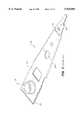
- FIG. 2is a plan view of a prior art suspension assembly having up-rails.
- FIG. 3is plan view of a prior art suspension assembly having down rails.
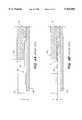
- FIG. 4ais a partial cross-sectional view of the suspension assembly of FIG. 2, assembled with a flanged disk clamp and a disk, illustrating the clearance between the load beam and the flange.
- FIG. 4billustrates the clearance shown in FIG. 4a, when assembly tolerance is considered.
- FIG. 5ais a partial cross-sectional view of the suspension assembly of FIG. 3, assembled with a flanged disk clamp and a disk, illustrating the clearance between the load beam and the flange.
- FIG. 5billustrates the clearance shown in FIG. 5a, when assembly tolerance is considered.
- FIG. 6ais a plan view of impact protrusions formed on the suspension assembly of FIG. 2, in accordance with principles of the present invention.
- FIG. 6bis a magnified side view of the distal end of the suspension assembly of FIG. 6a.
- FIG. 7ais a partial cross-sectional view of the suspension assembly of FIG. 6a, assembled with a flanged disk clamp and a disk, illustrating the clearance between the load beam and the flange.
- FIG. 7billustrates the clearance shown in FIG. 7a, when assembly tolerance is considered.
- FIG. 7cis a magnified view of a distal end of the suspension assembly shown in FIG. 7b.
- FIG. 8ais a plan view of an impact dimple formed on the suspension assembly of FIG. 3, in accordance with principles of the present invention.
- FIG. 8bis a side view of the distal end of the suspension assembly of FIG. 8a.
- FIG. 9ais a partial cross-sectional view of the suspension assembly of FIG. 8a, assembled with a flanged disk clamp and a disk, illustrating the clearance between the load beam and the flange.
- FIG. 9billustrates the clearance shown in FIG. 9a, when assembly tolerance is considered.
- FIG. 10is a plot illustrating the relationship of clearance between suspension and flange vs. stack-up, with various protrusion heights.
- FIG. 11is a plan view of an impact dimple formed on a suspension assembly having a load beam without side rails.
- the present inventionis shown in FIG. 6a, wherein an impact protrusion 55 is formed at the distal end of each up-rail 24 of load beam 20.
- the magnified view of FIG. 6bshows in detail that the protrusion is preferably generally semi-circular in shape and is integrally formed with the up-rails 24.
- the protrusionis preferably defined by a radius of curvature R, as measured from a contact point 26 between the load dimple 26 and slider 29. Contact point 26 also defines a "center of rotation" of load beam 20, when vertical stack-up is introduced.
- the center of rotationis an effect resulting from vertical stack-up, which tends to displace the load beam 20 in the vertical direction, and the preload force, which tends to bias the distal end from displacement away from the disk surface.
- the resulting effectis illustrated in FIG. 7c, wherein load beam 20 has been rotated, from the position shown in FIG. 6b, through an angle ⁇ , about contact point 26.
- the advantage of defining R from contact point 26is that clearance c remains unchanged when vertical stack-up is introduced since contact point 26 coincides with the center of rotation.
- FIG. 7astack-up height h, clearance i, defining the distance between the up-rail 24 and spacer flange 12b having a thickness of t', and clearance c, defining the distance between impact protrusion 55 and the flange 12b.
- Thickness t'represents a reduced flange thickness t of the prior art, shown in FIG. 4a, to effectively create an increased clearance i.
- t'is half the thickness of t. Clearance i is sufficient to prevent interference between the flange 12b and up-rail 24 due to stack-up.
- the reduced flange thickness t'compensates for stack-up while the impact protrusions 55 limit slider displacement from the disk surface. It should be understood that without protrusions 55, reduced thickness t' undesirably creates a sufficiently large enough clearance c to enable head slap.
- impact protrusion 55may be conveniently etched and formed with the fabrication of the up-rail load beam 20. Impact protrusion 55 is formed near, but not coincident with load dimple 25. While chemical etching is presently most preferred, other forming methods, such as stamping, ion milling, micromachining, etc., may also be employed.
- FIG. 8aAn alternative embodiment of the present invention is shown in FIG. 8a.
- an impact featureis defined as a dimple 65 formed away from slider 29, towards the flange.
- the impact dimple 65is preferably generally spherical shaped, positioned along a longitudinal axis of the suspension, in close proximity to the load dimple 25.
- impact dimple 65is preferably formed as close to load dimple as manufacturably possible. This way, any decrease to clearance c, resulting from rotation of the load beam due to vertical stack-up, may be minimized.
- 9a and 9bshow similar advantages of forming an impact dimple 65 on a down-rail load beam 30, wherein a sufficient clearance i' minimizes the possibility of collision between the load beam 30 and the flange 12b. At the same time head slap is prevented as clearance c, defined between dimple 65 and flange 12b remains relatively unchanged.
- FIG. 11shows yet another embodiment of the present invention, where an impact dimple 85 is formed in a rail-less load beam 80.
- the impact dimple 85is similarly formed and shaped as the impact dimple 65 formed into load beam 30, shown in FIG. 8a.
- Load beam 80is generally identical to load beam 30 with the exception that load beam 80 is fabricated without stiffening side rails.
- Lrepresents the effective length of the load beam 20.
- the vertical axisshows the maximum tolerable z-height shift (stack-up) h of the E-block arm before an interference results between the up rail 24 and flange 12b. Based on the plot of FIG. 10, it is evident that clearance c and allowable stack-up h of the E-block arm are directly related as are the impact feature height r and the allowable stack-up h.
- FIG. 10shows that it is preferable to form each protrusion 55 with a height r of approximately 0.10-0.15 mm.
- the impact featuresare located along the load beam longitudinal axis, in close proximity to a rotational center of the load beam.
- the rotational centeris located along the "pitch axis", i.e. the axis transversely perpendicular to the longitudinal axis of the load beam, also known as the "roll axis". Since the load beam preload force urges the slider against the disk surface, such that the slider maintains contact with the disk at the landing zone when the drive is not in operation, clearance c remains relatively unchanged as the load beam rotates due to disk and arm stack-up.
Landscapes
- Supporting Of Heads In Record-Carrier Devices (AREA)
Abstract
Description
i=(r+c)-S θ (1)
h=(L/S)c+L(r/s-θ) (2)
h=(L/S)c+L(r/S) (3)
Claims (17)
Priority Applications (4)
| Application Number | Priority Date | Filing Date | Title |
|---|---|---|---|
| US08/978,857US5936804A (en) | 1997-11-26 | 1997-11-26 | Impact features on suspensions for improved damage resiliancy in disk drives |
| JP52934599AJP2001509939A (en) | 1997-11-26 | 1998-11-24 | Impact resistant structure of suspension with improved resilience to damage in disk drives |
| EP98959602AEP0954862A1 (en) | 1997-11-26 | 1998-11-24 | Impact features on suspensions for improved damage resiliancy in disk drives |
| PCT/US1998/025156WO1999027533A1 (en) | 1997-11-26 | 1998-11-24 | Impact features on suspensions for improved damage resiliancy in disk drives |
Applications Claiming Priority (1)
| Application Number | Priority Date | Filing Date | Title |
|---|---|---|---|
| US08/978,857US5936804A (en) | 1997-11-26 | 1997-11-26 | Impact features on suspensions for improved damage resiliancy in disk drives |
Publications (1)
| Publication Number | Publication Date |
|---|---|
| US5936804Atrue US5936804A (en) | 1999-08-10 |
Family
ID=25526456
Family Applications (1)
| Application Number | Title | Priority Date | Filing Date |
|---|---|---|---|
| US08/978,857Expired - Fee RelatedUS5936804A (en) | 1997-11-26 | 1997-11-26 | Impact features on suspensions for improved damage resiliancy in disk drives |
Country Status (4)
| Country | Link |
|---|---|
| US (1) | US5936804A (en) |
| EP (1) | EP0954862A1 (en) |
| JP (1) | JP2001509939A (en) |
| WO (1) | WO1999027533A1 (en) |
Cited By (12)
| Publication number | Priority date | Publication date | Assignee | Title |
|---|---|---|---|---|
| US6351350B1 (en) | 1999-12-09 | 2002-02-26 | Hutchinson Technology Incorporated | Shock limiter system for a head suspension |
| US6504684B1 (en) | 1999-12-27 | 2003-01-07 | Hutchinson Technology Incorporated | Head suspension with integral shock limiter |
| US20030011935A1 (en)* | 2001-07-12 | 2003-01-16 | Nhk Spring Co., Ltd | Disc drive suspension |
| US6556383B2 (en)* | 1998-11-18 | 2003-04-29 | Seagate Technology Llc | Disc drive anti-shock suspension cushions |
| US20030086207A1 (en)* | 2001-11-08 | 2003-05-08 | Nhk Spring Co., Ltd. | Disc drive suspension |
| US20040100725A1 (en)* | 2002-11-21 | 2004-05-27 | Shiao-Hua Chen | Damped disk spacer |
| US6768612B2 (en)* | 2001-12-07 | 2004-07-27 | Nhk Spring Co., Ltd. | Disc drive suspension having an independent hinge member |
| US20060139811A1 (en)* | 2004-12-28 | 2006-06-29 | Samsung Electronics Co., Ltd. | Suspension and actuator with the same for use in hard disk drive |
| US20060209466A1 (en)* | 2004-12-14 | 2006-09-21 | Kyosuke Ono | Head suspension mechanism |
| US7149054B1 (en) | 2000-05-18 | 2006-12-12 | Hutchinson Technology Incorporated | Reverse flow disk drive and head suspension for same |
| US20070121243A1 (en)* | 2005-10-27 | 2007-05-31 | Samsung Electronics Co., Ltd. | Spindle motor assembly and hard disk drive having the same |
| US20070285845A1 (en)* | 2006-06-08 | 2007-12-13 | Quantum Corporation, A Delaware Corporation | Narrow width actuator for tape drive systems |
Families Citing this family (1)
| Publication number | Priority date | Publication date | Assignee | Title |
|---|---|---|---|---|
| JP4367712B2 (en)* | 2005-03-30 | 2009-11-18 | 日本発條株式会社 | Head suspension |
Citations (4)
| Publication number | Priority date | Publication date | Assignee | Title |
|---|---|---|---|---|
| US5027241A (en)* | 1989-06-01 | 1991-06-25 | Quantum Corporation | Data head load beam for height compacted, low power fixed head and disk assembly |
| US5065268A (en)* | 1989-12-22 | 1991-11-12 | Seagate Technology, Inc. | Load beam having an additional bend in a head-gimbal assembly |
| US5239431A (en)* | 1992-02-26 | 1993-08-24 | Hewlett-Packard Company | Head lift limiter for a disk drive |
| US5543985A (en)* | 1994-06-13 | 1996-08-06 | Quantum Corporation | "Acton" load beam for a winchester disk drive |
Family Cites Families (3)
| Publication number | Priority date | Publication date | Assignee | Title |
|---|---|---|---|---|
| JPS5611657A (en)* | 1979-07-10 | 1981-02-05 | Mitsubishi Electric Corp | Magnetic head support mechanism |
| DE3562057D1 (en)* | 1984-01-26 | 1988-05-05 | Memorex Corp | Arch flexure for winchester sliders |
| JP2930505B2 (en)* | 1993-07-15 | 1999-08-03 | アルプス電気株式会社 | Levitated magnetic head device |
- 1997
- 1997-11-26USUS08/978,857patent/US5936804A/ennot_activeExpired - Fee Related
- 1998
- 1998-11-24JPJP52934599Apatent/JP2001509939A/enactivePending
- 1998-11-24EPEP98959602Apatent/EP0954862A1/ennot_activeWithdrawn
- 1998-11-24WOPCT/US1998/025156patent/WO1999027533A1/ennot_activeApplication Discontinuation
Patent Citations (4)
| Publication number | Priority date | Publication date | Assignee | Title |
|---|---|---|---|---|
| US5027241A (en)* | 1989-06-01 | 1991-06-25 | Quantum Corporation | Data head load beam for height compacted, low power fixed head and disk assembly |
| US5065268A (en)* | 1989-12-22 | 1991-11-12 | Seagate Technology, Inc. | Load beam having an additional bend in a head-gimbal assembly |
| US5239431A (en)* | 1992-02-26 | 1993-08-24 | Hewlett-Packard Company | Head lift limiter for a disk drive |
| US5543985A (en)* | 1994-06-13 | 1996-08-06 | Quantum Corporation | "Acton" load beam for a winchester disk drive |
Cited By (19)
| Publication number | Priority date | Publication date | Assignee | Title |
|---|---|---|---|---|
| US6556383B2 (en)* | 1998-11-18 | 2003-04-29 | Seagate Technology Llc | Disc drive anti-shock suspension cushions |
| US6351350B1 (en) | 1999-12-09 | 2002-02-26 | Hutchinson Technology Incorporated | Shock limiter system for a head suspension |
| US6504684B1 (en) | 1999-12-27 | 2003-01-07 | Hutchinson Technology Incorporated | Head suspension with integral shock limiter |
| US7149054B1 (en) | 2000-05-18 | 2006-12-12 | Hutchinson Technology Incorporated | Reverse flow disk drive and head suspension for same |
| US6765760B2 (en) | 2001-07-12 | 2004-07-20 | Nhk Spring Co., Ltd. | Disc drive suspension |
| US20030011935A1 (en)* | 2001-07-12 | 2003-01-16 | Nhk Spring Co., Ltd | Disc drive suspension |
| US20030086207A1 (en)* | 2001-11-08 | 2003-05-08 | Nhk Spring Co., Ltd. | Disc drive suspension |
| US6768612B2 (en)* | 2001-12-07 | 2004-07-27 | Nhk Spring Co., Ltd. | Disc drive suspension having an independent hinge member |
| US20040150919A1 (en)* | 2001-12-07 | 2004-08-05 | Nhk Spring Co., Ltd. | Disc drive suspension |
| US6920017B2 (en) | 2001-12-07 | 2005-07-19 | Nhk Spring Co., Ltd. | Disc drive suspension having an offset portion for mounting an end of a flexure |
| US20040100725A1 (en)* | 2002-11-21 | 2004-05-27 | Shiao-Hua Chen | Damped disk spacer |
| US20060209466A1 (en)* | 2004-12-14 | 2006-09-21 | Kyosuke Ono | Head suspension mechanism |
| US7606001B2 (en)* | 2004-12-14 | 2009-10-20 | Naruse, Jun | Vibration reducing head suspension mechanism for a magnetic disc unit |
| US20090316305A1 (en)* | 2004-12-14 | 2009-12-24 | Jun Naruse | Vibration reducing head suspension mechanism for a magnetic disc unit |
| US7755865B2 (en) | 2004-12-14 | 2010-07-13 | Jun Naruse | Vibration reducing head suspension mechanism for a magnetic disc unit |
| US20060139811A1 (en)* | 2004-12-28 | 2006-06-29 | Samsung Electronics Co., Ltd. | Suspension and actuator with the same for use in hard disk drive |
| US20070121243A1 (en)* | 2005-10-27 | 2007-05-31 | Samsung Electronics Co., Ltd. | Spindle motor assembly and hard disk drive having the same |
| US20070285845A1 (en)* | 2006-06-08 | 2007-12-13 | Quantum Corporation, A Delaware Corporation | Narrow width actuator for tape drive systems |
| US7679864B2 (en)* | 2006-06-08 | 2010-03-16 | Quantum Corporation | Narrow width actuator for tape drive systems |
Also Published As
| Publication number | Publication date |
|---|---|
| WO1999027533A1 (en) | 1999-06-03 |
| EP0954862A1 (en) | 1999-11-10 |
| JP2001509939A (en) | 2001-07-24 |
Similar Documents
| Publication | Publication Date | Title |
|---|---|---|
| KR100275179B1 (en) | Disc driver apparatus | |
| US6452753B1 (en) | Universal load/unload ramp | |
| US5936804A (en) | Impact features on suspensions for improved damage resiliancy in disk drives | |
| US5898545A (en) | Head load/unload and disk airflow control apparatus | |
| US6344950B1 (en) | Head disk assembly including ramp having pivoting locational features | |
| US5341260A (en) | Reduced torque unloading ramp system for a hard disk drive | |
| US7554771B2 (en) | Tolerance ring for data storage with overlapping tab feature for mass control | |
| US6233121B1 (en) | Magnetic disk drive suspension pitch motion limiter | |
| EP0108500A1 (en) | Apparatus for positioning a head relative to a magnetic disc | |
| JPH0887841A (en) | Actuator arm assembly and disk drive system | |
| US20050157428A1 (en) | Suspension assembly having flexure limiter and actuator for disk drive adopting the same | |
| US5768058A (en) | Crash stop airlock mechanism | |
| US6765762B2 (en) | Disk drive with a parking ramp for parking heads | |
| CN103811026A (en) | Flexible ramp in a hard disk drive | |
| US20070188929A1 (en) | Actuator Load/Unload Ramp | |
| US6888699B2 (en) | Disc drive clamp having centering features | |
| US6172852B1 (en) | Actuator assembly for a disc drive having stacked actuator arms with interlocked asperities on mating surfaces | |
| KR100532495B1 (en) | Suspension assembly having reinforced end-tab and actuator for disk drive adopting the same | |
| JP2004171749A (en) | Actuator pivot assembly for disk drive with corrugated ring | |
| KR100234652B1 (en) | Slider with shallow etch air bearing surface and manufacturing method thereof | |
| US7027266B2 (en) | Head suspension with flexure-supported slider between first and second load bending portions | |
| US20050078407A1 (en) | Base plate design for reducing deflection of suspension assembly by swaging | |
| US5124865A (en) | Microminimonolithic magnetic head slider having vertically extending slots to reduce flux leakage losses | |
| US6330209B1 (en) | Load and unload control for magneto-optical disk drive | |
| EP1638086A2 (en) | Disk drive suspension assembly and recording and/or reproducing apparatus with suspension assembly |
Legal Events
| Date | Code | Title | Description |
|---|---|---|---|
| AS | Assignment | Owner name:QUANTUM CORPORATION, CALIFORNIA Free format text:ASSIGNMENT OF ASSIGNORS INTEREST;ASSIGNORS:RIENER, TIMOTHY A.;WILLIAMS, STEPHEN P.;REEL/FRAME:008840/0025 Effective date:19971125 | |
| AS | Assignment | Owner name:MAXTOR CORPORATION, CALIFORNIA Free format text:ASSIGNMENT OF ASSIGNORS INTEREST;ASSIGNOR:QUANTUM CORPORATION;REEL/FRAME:012653/0726 Effective date:20010724 | |
| FPAY | Fee payment | Year of fee payment:4 | |
| FPAY | Fee payment | Year of fee payment:8 | |
| AS | Assignment | Owner name:WELLS FARGO BANK, NATIONAL ASSOCIATION, AS COLLATERAL AGENT AND SECOND PRIORITY REPRESENTATIVE, CALIFORNIA Free format text:SECURITY AGREEMENT;ASSIGNORS:MAXTOR CORPORATION;SEAGATE TECHNOLOGY LLC;SEAGATE TECHNOLOGY INTERNATIONAL;REEL/FRAME:022757/0017 Effective date:20090507 Owner name:JPMORGAN CHASE BANK, N.A., AS ADMINISTRATIVE AGENT AND FIRST PRIORITY REPRESENTATIVE, NEW YORK Free format text:SECURITY AGREEMENT;ASSIGNORS:MAXTOR CORPORATION;SEAGATE TECHNOLOGY LLC;SEAGATE TECHNOLOGY INTERNATIONAL;REEL/FRAME:022757/0017 Effective date:20090507 Owner name:JPMORGAN CHASE BANK, N.A., AS ADMINISTRATIVE AGENT Free format text:SECURITY AGREEMENT;ASSIGNORS:MAXTOR CORPORATION;SEAGATE TECHNOLOGY LLC;SEAGATE TECHNOLOGY INTERNATIONAL;REEL/FRAME:022757/0017 Effective date:20090507 Owner name:WELLS FARGO BANK, NATIONAL ASSOCIATION, AS COLLATE Free format text:SECURITY AGREEMENT;ASSIGNORS:MAXTOR CORPORATION;SEAGATE TECHNOLOGY LLC;SEAGATE TECHNOLOGY INTERNATIONAL;REEL/FRAME:022757/0017 Effective date:20090507 | |
| AS | Assignment | Owner name:SEAGATE TECHNOLOGY HDD HOLDINGS, CALIFORNIA Free format text:RELEASE;ASSIGNOR:JPMORGAN CHASE BANK, N.A., AS ADMINISTRATIVE AGENT;REEL/FRAME:025662/0001 Effective date:20110114 Owner name:MAXTOR CORPORATION, CALIFORNIA Free format text:RELEASE;ASSIGNOR:JPMORGAN CHASE BANK, N.A., AS ADMINISTRATIVE AGENT;REEL/FRAME:025662/0001 Effective date:20110114 Owner name:SEAGATE TECHNOLOGY INTERNATIONAL, CALIFORNIA Free format text:RELEASE;ASSIGNOR:JPMORGAN CHASE BANK, N.A., AS ADMINISTRATIVE AGENT;REEL/FRAME:025662/0001 Effective date:20110114 Owner name:SEAGATE TECHNOLOGY LLC, CALIFORNIA Free format text:RELEASE;ASSIGNOR:JPMORGAN CHASE BANK, N.A., AS ADMINISTRATIVE AGENT;REEL/FRAME:025662/0001 Effective date:20110114 | |
| REMI | Maintenance fee reminder mailed | ||
| AS | Assignment | Owner name:THE BANK OF NOVA SCOTIA, AS ADMINISTRATIVE AGENT, CANADA Free format text:SECURITY AGREEMENT;ASSIGNOR:SEAGATE TECHNOLOGY LLC;REEL/FRAME:026010/0350 Effective date:20110118 Owner name:THE BANK OF NOVA SCOTIA, AS ADMINISTRATIVE AGENT, Free format text:SECURITY AGREEMENT;ASSIGNOR:SEAGATE TECHNOLOGY LLC;REEL/FRAME:026010/0350 Effective date:20110118 | |
| LAPS | Lapse for failure to pay maintenance fees | ||
| STCH | Information on status: patent discontinuation | Free format text:PATENT EXPIRED DUE TO NONPAYMENT OF MAINTENANCE FEES UNDER 37 CFR 1.362 | |
| FP | Lapsed due to failure to pay maintenance fee | Effective date:20110810 | |
| AS | Assignment | Owner name:SEAGATE TECHNOLOGY US HOLDINGS, INC., CALIFORNIA Free format text:TERMINATION AND RELEASE OF SECURITY INTEREST IN PATENT RIGHTS;ASSIGNOR:WELLS FARGO BANK, NATIONAL ASSOCIATION, AS COLLATERAL AGENT AND SECOND PRIORITY REPRESENTATIVE;REEL/FRAME:030833/0001 Effective date:20130312 Owner name:SEAGATE TECHNOLOGY INTERNATIONAL, CAYMAN ISLANDS Free format text:TERMINATION AND RELEASE OF SECURITY INTEREST IN PATENT RIGHTS;ASSIGNOR:WELLS FARGO BANK, NATIONAL ASSOCIATION, AS COLLATERAL AGENT AND SECOND PRIORITY REPRESENTATIVE;REEL/FRAME:030833/0001 Effective date:20130312 Owner name:SEAGATE TECHNOLOGY LLC, CALIFORNIA Free format text:TERMINATION AND RELEASE OF SECURITY INTEREST IN PATENT RIGHTS;ASSIGNOR:WELLS FARGO BANK, NATIONAL ASSOCIATION, AS COLLATERAL AGENT AND SECOND PRIORITY REPRESENTATIVE;REEL/FRAME:030833/0001 Effective date:20130312 Owner name:EVAULT INC. (F/K/A I365 INC.), CALIFORNIA Free format text:TERMINATION AND RELEASE OF SECURITY INTEREST IN PATENT RIGHTS;ASSIGNOR:WELLS FARGO BANK, NATIONAL ASSOCIATION, AS COLLATERAL AGENT AND SECOND PRIORITY REPRESENTATIVE;REEL/FRAME:030833/0001 Effective date:20130312 | |
| AS | Assignment | Owner name:SEAGATE TECHNOLOGY PUBLIC LIMITED COMPANY, CALIFORNIA Free format text:RELEASE BY SECURED PARTY;ASSIGNOR:THE BANK OF NOVA SCOTIA;REEL/FRAME:072193/0001 Effective date:20250303 Owner name:SEAGATE TECHNOLOGY, CALIFORNIA Free format text:RELEASE BY SECURED PARTY;ASSIGNOR:THE BANK OF NOVA SCOTIA;REEL/FRAME:072193/0001 Effective date:20250303 Owner name:SEAGATE TECHNOLOGY HDD HOLDINGS, CALIFORNIA Free format text:RELEASE BY SECURED PARTY;ASSIGNOR:THE BANK OF NOVA SCOTIA;REEL/FRAME:072193/0001 Effective date:20250303 Owner name:I365 INC., CALIFORNIA Free format text:RELEASE BY SECURED PARTY;ASSIGNOR:THE BANK OF NOVA SCOTIA;REEL/FRAME:072193/0001 Effective date:20250303 Owner name:SEAGATE TECHNOLOGY LLC, CALIFORNIA Free format text:RELEASE BY SECURED PARTY;ASSIGNOR:THE BANK OF NOVA SCOTIA;REEL/FRAME:072193/0001 Effective date:20250303 Owner name:SEAGATE TECHNOLOGY INTERNATIONAL, CAYMAN ISLANDS Free format text:RELEASE BY SECURED PARTY;ASSIGNOR:THE BANK OF NOVA SCOTIA;REEL/FRAME:072193/0001 Effective date:20250303 Owner name:SEAGATE HDD CAYMAN, CAYMAN ISLANDS Free format text:RELEASE BY SECURED PARTY;ASSIGNOR:THE BANK OF NOVA SCOTIA;REEL/FRAME:072193/0001 Effective date:20250303 Owner name:SEAGATE TECHNOLOGY (US) HOLDINGS, INC., CALIFORNIA Free format text:RELEASE BY SECURED PARTY;ASSIGNOR:THE BANK OF NOVA SCOTIA;REEL/FRAME:072193/0001 Effective date:20250303 |