US5936529A - Electronic monitoring system - Google Patents
Electronic monitoring systemDownload PDFInfo
- Publication number
- US5936529A US5936529AUS08/899,610US89961097AUS5936529AUS 5936529 AUS5936529 AUS 5936529AUS 89961097 AUS89961097 AUS 89961097AUS 5936529 AUS5936529 AUS 5936529A
- Authority
- US
- United States
- Prior art keywords
- electronic monitoring
- monitoring device
- data processor
- program
- subject
- Prior art date
- Legal status (The legal status is an assumption and is not a legal conclusion. Google has not performed a legal analysis and makes no representation as to the accuracy of the status listed.)
- Expired - Lifetime
Links
- 238000012544monitoring processMethods0.000titleclaimsabstractdescription36
- 238000012806monitoring deviceMethods0.000claimsabstractdescription126
- 230000000694effectsEffects0.000claimsabstractdescription16
- 238000004891communicationMethods0.000claimsabstractdescription5
- 238000012545processingMethods0.000claimsdescription5
- 101000741965Homo sapiens Inactive tyrosine-protein kinase PRAG1Proteins0.000description10
- 102100038659Inactive tyrosine-protein kinase PRAG1Human genes0.000description10
- 230000005540biological transmissionEffects0.000description7
- 210000003423ankleAnatomy0.000description5
- 210000000707wristAnatomy0.000description5
- 230000006698inductionEffects0.000description4
- 230000008672reprogrammingEffects0.000description4
- 230000000994depressogenic effectEffects0.000description3
- 238000013475authorizationMethods0.000description2
- 210000003414extremityAnatomy0.000description2
- 230000000007visual effectEffects0.000description2
- 241001465754MetazoaSpecies0.000description1
- 230000001413cellular effectEffects0.000description1
- 230000000295complement effectEffects0.000description1
- 239000004020conductorSubstances0.000description1
- 238000010276constructionMethods0.000description1
- 125000004122cyclic groupChemical group0.000description1
- 238000010586diagramMethods0.000description1
- 238000012986modificationMethods0.000description1
- 230000004048modificationEffects0.000description1
- 238000005070samplingMethods0.000description1
Images


Classifications
- G—PHYSICS
- G08—SIGNALLING
- G08B—SIGNALLING OR CALLING SYSTEMS; ORDER TELEGRAPHS; ALARM SYSTEMS
- G08B21/00—Alarms responsive to a single specified undesired or abnormal condition and not otherwise provided for
- G08B21/18—Status alarms
- G08B21/22—Status alarms responsive to presence or absence of persons
- G—PHYSICS
- G07—CHECKING-DEVICES
- G07C—TIME OR ATTENDANCE REGISTERS; REGISTERING OR INDICATING THE WORKING OF MACHINES; GENERATING RANDOM NUMBERS; VOTING OR LOTTERY APPARATUS; ARRANGEMENTS, SYSTEMS OR APPARATUS FOR CHECKING NOT PROVIDED FOR ELSEWHERE
- G07C9/00—Individual registration on entry or exit
- G07C9/20—Individual registration on entry or exit involving the use of a pass
- G07C9/28—Individual registration on entry or exit involving the use of a pass the pass enabling tracking or indicating presence
Definitions
- the present inventionrelates to electronic monitoring devices, and particularly to such devices to be attached to a person for monitoring the movements or other activities of the person.
- the inventionalso relates to an electronic monitoring system including such devices.
- Such electronic monitoring devicestypically include a tamper sensor for sensing tampering with the device or removal of the device from the person to whom the device was attached, and for producing a corresponding tamper signal which is processed by a data processor and which is fed, with an identification signal identifying the respective device, to a transmitter for transmission to an external receiver.
- the external receivermay be a stationary one or a mobile one. Frequently, the receiver is a local one located in the immediate area of the confinement and transmits its information to a central station which monitors the activities of many persons having electronic monitoring devices attached to them.
- Such electronic monitoring devicesare quite expensive, and it would therefore be desirable to construct them for reuse.
- different subjectsmay require different monitoring programs, e.g., regarding the sampling intervals, the data transmission intervals, the monitored time periods, the locations barred or permitted to the subject, etc.
- One systemnow in use programs each monitoring device according to a specific program, and uses the monitoring device only on subjects to be monitored according to the respective program.
- An object of the present inventionis to provide an electronic monitoring system including an electronic monitoring device of the foregoing type to be applied to the subject, and a resetting device which enables the monitoring device to be reset in a quick and simple manner, by reprogramming it for use with a different subject, or by disabling it for conserving battery power when the device is returned to inventory for future use.
- an electronic monitoring systemcomprising: an electronic monitoring device including a housing attachable to a subject for monitoring, at a remote location, movements and/or other activities of the subject; a closure member to secure the housing to the subject; and electronic circuitry including a data processor and a transmitter within the housing for receiving, processing, and transmitting to the remote location data regarding the activities of the subject; the data processor including a memory for storing the identification of the electronic monitoring device and the operational program of its data processor; and a manual resetting device having electrical terminals adapted to be brought into communication with electrical terminals on the electronic monitoring device when the closure member is removed therefrom, for resetting the electronic monitoring device.
- the manual resetting devicefurther includes a data processor storing a program to be downloaded into the memory of the data processor in the electronic monitoring device; an "Enable” key for enabling the electronic monitoring device and for downloading the program thereto; and a “Disable” key for disabling the electronic monitoring device.
- the manual resetting deviceincludes an indicator controlled by its data processor to indicate whether the electronic monitoring device has been successfully reset.
- each manual resetting devicefurther includes a unique identification number stored therein; and the data processor of the manual resetting device is programmed to download the identification into the memory of the data processor in the electronic monitoring device when resetting the electronic monitoring device.
- the data processor of the manual resetting deviceis programmed, when downloading a program into the memory of the data processor in the electronic monitoring device, also to command the electronic monitoring device to store and periodically transmit the identification of the manual resetting device with the other data transmitted by the electronic monitoring device to the remote location.
- the data processor of the manual resetting deviceis programmed, when downloading a program into the memory of the data processor in the electronic monitoring device, also to receive and to store the identification of each electronic monitoring device reset thereby, and also the program downloaded thereto.
- FIG. 1illustrates one form of electronic monitoring system constructed in accordance with the present invention
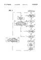
- FIG. 2is a block diagram illustrating the main electrical components in the electronic monitoring device and manual resetting device in the system of FIG. 1;
- FIG. 3is a flowchart illustrating one example of operation of the manual resetting device in the system illustrated in the drawings;
- FIG. 4is a flowchart illustrating one example of operation of the electronic monitoring device in the system illustrated in the drawings.
- FIG. 1illustrates an electronic monitoring device, generally designated 2, to be attached to a person for monitoring movements and other activities of the person. These activities as detected by monitoring device 2 are transmitted to a local receiver 3 located in the general area of the person being monitored, such as the person's home residence. The information received by the local receiver 3 is in turn transmitted to a remote monitor 4 which monitors the activities of a number of persons each equipped with a personal monitoring device 2.
- the transmission from the monitoring device 2 to the local receiver 3is by wireless transmission; and the transmission from local receiver 3 to the remote monitor 4 may be by wireless transmission or by wires, e.g., via the regular telephone or a cellular telephone.
- Electronic monitoring device 2includes a housing 10 for housing the electronic circuitry, and a pair of straps 11, 12 defining a band for attaching the housing to a limb preferably the ankle or wrist of the person to be monitored.
- both straps 11 and 12are provided with a plurality of pairs of holes 11a, 12a along their lengths, cooperable with a closure member 13 for fixing the effective lengths of the two straps according to the size of the person's ankle or wrist.
- Closure member 13includes two parts 13a, 13b to be disposed on the opposite sides of the overlapping ends of the two straps 11, 12 after the monitoring device has been applied to the person.
- Part 13aincludes four pins 14, and part 13b includes four complementary sockets 15, such that after the ends of the two straps 11, 12 have been applied around the person's ankle (or wrist), pins 14 of part 13a may be passed through the appropriate aligned holes 11a, 12a, of the overlapping ends of the two straps 11, 12, and force-fitted into their respective sockets 15 of part 13b, to fix the monitoring device to the person's ankle (or wrist).
- the illustrated monitoring device 2further includes a tamper sensor for sensing any tampering with the monitoring devices or its removal from the person to whom it was attached.
- the tamper sensor in the illustrated monitoring devicemay be the same as described in the above-cited U.S. Pat. No. 5,504,474.
- Such a sensorincludes electrical conductors (not shown) extending through the two straps 11, 12, electrical terminals 16 provided in the end of strap 12, and electrical pads 17 formed in part 13a engageable by terminals 16 when the two parts 13a, 13b of the closure member 13 are fixed as required to the overlapping ends of the two straps.
- the arrangementis that any cutting of strap 11 or 12, or any attempt to separate the two parts 13a, 13b from the straps, will result in a break in the continuity of the electrical circuit which would be sensed by the electrical circuitry within housing 10.
- manual resetting device 20may be used for both disabling the electronic monitoring device 2 so that the device can be placed back into inventory for future use without draining the battery, or for reprogramming the device for use by another subject, which reprogram may be the same as the previous one or a different one.
- the manual resetting device 20when used for resetting the electronic circuitry within housing 10 of the monitoring device, also downloads the identification number of the manual resetting device into the memory of the monitoring device and commands the monitoring device to periodically transmit the identification of the resetting device with the data transferred to the remote location.
- such a manual resetting devicenot only simplifies resetting a monitoring device, but also assures that the resetting device will always be identified so that an unauthorized resetting of the monitoring device will be quickly detected.
- the manual resetting deviceis shown at 20 in FIG. 1. Its electrical circuitry, as well as the electrical circuitry of the electronic monitoring device 2, is shown in FIG. 2.
- the manual resetting device 20is enclosed within a housing 21 which may be constructed for easy portability. It includes two depressible keys: Disable key 22, and Enable key 23. It also includes an LED visual indicator 24. It further includes two terminals 25, which are connectible, e.g., either by direct contact or by induction, with two of the terminals 16 on strap 12 in order to communicate with the electronic circuitry within housing 10 of the monitoring device 2 after the closure member 13 has been removed.
- manual resetting device 20further includes a microprocessor 27 having a memory 28 storing the program to be downloaded into the electronic monitoring device 2, and also storing the identification number of the manual resetting device. This identification number is also downloaded and stored in the electronic monitoring device 2 when reset.
- memory 28 in the manual resetting device 20stores a number of programs which may be preselected for use when reprogramming another electronic monitoring device 2.
- the selection of any particular program of those storedis made at the factory by a program selector switch PS within housing 21; but it will be appreciated that the resetting device could include a selector switch externally of the housing to enable the user to preselect the desired program.
- Memory 28further includes a section for storing the identifications of all the electronic memory devices it presets, so that it can provide this information, including the programs applied in each case, whenever desired to an external data processor, e.g., for record purposes.
- This information stored within the manual resetting device 20may be read out of the resetting device in any suitable manner, e.g., by electrical contacts, induction, RF transmission, or by removal of the storage element.
- Microprocessor 27 and LED 24 of the manual resetting deviceare powered by a battery 29.
- FIG. 2also shows the electronic circuitry within housing 10 of the electronic monitoring device 2.
- This circuitryincludes a microprocessor 30 adapted to communicate, via terminals 16 and 25, with the manual resetting device 20, and a transmitter 31 connected to microprocessor 30 for transmitting the data processed therein to the remote location via antenna 32.
- Microprocessor 30further includes other inputs, e.g., an input from the open-closure sensor 33 and the body (proximity) sensor 34, for example as described in the above-cited U.S. Pat. No. 5,504,474 for processing the received information concerning the movements or other activities of the subject to which the monitoring device is attached, and for transmitting this information to the remote location via transmitter 31 and antenna 32.
- the microprocessor 30 and transmitter 31are powered by a battery 35 contained within the monitoring device.
- Data processor 30 of the monitoring device 2further includes a memory 36 for storing the program downloaded from the manual resetting device 20, its identification, and also the identification of the manual resetting devices used for resetting it.
- the latter identificationis transmitted with the other data to the remote location not only to inform of authorized resettings, but also to assure that any unauthorized resetting or reprogramming of the monitoring device, or attempt with respect thereto will not go undetected.
- part 13a of the closure member 13may be removed in order to provide access to terminals 16 in strap 12 of the monitoring device 2.
- the manual resetting device 20is held with its terminals 25 in contact with terminals 16 of the monitoring device, or in induction proximity with terminal 16 (e.g., without removing part 13a of the closure member). If the monitoring device is to be disabled, Disable key 22 is depressed; and if the monitoring device is to be enabled, Enable key 23 is depressed to download the enabling program of the manual resetting device into the monitoring device.
- the LED 24is energized with an acknowledging "ACK” signal (e.g., producing slow blinks) when the manual resetting has been successfully completed, and with a not-acknowledging “NACK” signal (e.g., producing rapid blinks) when the manual resetting has not been successfully completed.
- ACKacknowledging
- NACKnot-acknowledging
- a new closure member part 13ais attached to part 13b and the overlapping ends of the straps 11, 12, or both new closure parts 13a, 13b may be attached to the overlapping ends of the straps, to fix these ends according to the size of the wrist or ankle of the subject to which the monitoring device is to be attached, and also to establish the necessary continuity between pins 16 of strap 12 and pads 17 of closure member part 13a.
- FIG. 3is a flowchart illustrating an example of the operational program of microprocessor 27 in the manual resetting device 20; and FIG. 4 is a flowchart illustrating an example of the operational program of microprocessor 30 in the electronic monitoring device 2.
- the microprocessorfirst checks to see whether a button is depressed (block 40), and if so, it transmits to the electronic monitoring device 2 the operation specified by the push button (i.e., "Disable” or “Enable") and also the identification of the respective manual resetting device (block 41).
- a timer within microprocessor 27is then started (block 42), e.g., to time three seconds, and a check is made to determine whether a message is received from the electronic monitoring device within that time period (blocks 43, 44); if not, the LED 24 is blinked (e.g., rapidly), or continuously energized to indicate "NACK" (block 45).
- a legality checkis then made (block 53) to determine whether that electronic monitoring device is allowed to communicate with the specific manual resetting device; for example, if the manual resetting device is on a "Stolen list", the result of this check would be negative. If such a check is found to be negative, the electronic monitoring device transmits to the local receiver (3, FIG. 1), sometime within the coming week, a report informing the local receiver periodically (e.g., every five minutes) the identification of the commanding manual resetting device (block 54), and also sends a "NACK" signal to the manual resetting device (block 52).
- the "Authorization” check performed in block 55is made to assure that the specific electronic monitoring device is authorized to receive a command from the specific manual resetting device; for example, some electronic monitoring devices are authorized to receive only certain commands from supervisors.
- the "Ability to Perform” check (block 56)is made to assure that the electronic monitoring device is capable of executing the command; for example, if its battery is too low, it would produce a negative result when this check is made.
- the electronic monitoring devicetransmits an "ACK" signal to the data processor 27 of the manual resetting device 20 (block 57), stores the identification of the manual resetting device (block 58), and executes the command (block 59). Thereafter, within one week, it periodically (e.g., each five minutes) transmits to the local receiver 3 the identification of the commanding manual resetting device if not disabled.
- the remote locationwill be continuously advised of the identification of the manual resetting device that last reset the monitoring device, so that in case the manual resetting device was not an authorized one, this will be quickly detected.
- the resettingcan be effected in other manners, e.g., by induction without opening the closure member.
- the indicator 24is a visual one it could be an audio one.
- the monitoring devicemay be used for monitoring movements other than those under house arrest, e.g., movements of medical patients, children in shopping centers, animals, etc.
- the monitoring devicecould supply other information (in addition to the ID, ACK and NACK) to the resetting device, e.g. past failed attempts to reset, and other information to the remote location, e.g.
- the monitoring devicecould be applied to parts of a subject other than the limbs, e.g. around the neck or attached to subject's clothing. Many other variations, modifications and applications of the invention will be apparent.
Landscapes
- Physics & Mathematics (AREA)
- General Physics & Mathematics (AREA)
- Business, Economics & Management (AREA)
- Emergency Management (AREA)
- Alarm Systems (AREA)
- Burglar Alarm Systems (AREA)
- Measuring And Recording Apparatus For Diagnosis (AREA)
- Measurement Of The Respiration, Hearing Ability, Form, And Blood Characteristics Of Living Organisms (AREA)
- Emergency Alarm Devices (AREA)
Abstract
Description
Claims (16)
Priority Applications (5)
| Application Number | Priority Date | Filing Date | Title |
|---|---|---|---|
| US08/899,610US5936529A (en) | 1997-07-24 | 1997-07-24 | Electronic monitoring system |
| IL12548798AIL125487A (en) | 1997-07-24 | 1998-07-23 | Electronic monitoring system |
| EP98305925AEP0902401B1 (en) | 1997-07-24 | 1998-07-24 | Electronic monitoring system |
| AT98305925TATE241833T1 (en) | 1997-07-24 | 1998-07-24 | ELECTRONIC MONITORING SYSTEM |
| DE69815007TDE69815007D1 (en) | 1997-07-24 | 1998-07-24 | Electronic surveillance system |
Applications Claiming Priority (1)
| Application Number | Priority Date | Filing Date | Title |
|---|---|---|---|
| US08/899,610US5936529A (en) | 1997-07-24 | 1997-07-24 | Electronic monitoring system |
Publications (1)
| Publication Number | Publication Date |
|---|---|
| US5936529Atrue US5936529A (en) | 1999-08-10 |
Family
ID=25411286
Family Applications (1)
| Application Number | Title | Priority Date | Filing Date |
|---|---|---|---|
| US08/899,610Expired - LifetimeUS5936529A (en) | 1997-07-24 | 1997-07-24 | Electronic monitoring system |
Country Status (5)
| Country | Link |
|---|---|
| US (1) | US5936529A (en) |
| EP (1) | EP0902401B1 (en) |
| AT (1) | ATE241833T1 (en) |
| DE (1) | DE69815007D1 (en) |
| IL (1) | IL125487A (en) |
Cited By (63)
| Publication number | Priority date | Publication date | Assignee | Title |
|---|---|---|---|---|
| USD417407S (en) | 1999-04-08 | 1999-12-07 | Maryanne Palmieri Da Costa | Temperature monitoring transmitter and receiver |
| WO2000007155A3 (en)* | 1998-07-31 | 2000-09-28 | Beryl E Pitzer | Personal monitoring system |
| USD440170S1 (en) | 2000-08-18 | 2001-04-10 | Jerry G Conerly | Child locator wrist watch |
| US6255951B1 (en)* | 1996-12-20 | 2001-07-03 | Carlos De La Huerga | Electronic identification bracelet |
| US6346886B1 (en)* | 1996-12-20 | 2002-02-12 | Carlos De La Huerga | Electronic identification apparatus |
| US6392312B1 (en)* | 1999-10-26 | 2002-05-21 | Gary Jay Morris | Portable electric power generator with remote control and safety apparatus |
| US6445300B1 (en)* | 2001-06-19 | 2002-09-03 | Hewlett-Packard Company | Personal emergency information transmitter |
| US20030038720A1 (en)* | 2001-07-07 | 2003-02-27 | Shugrue John K. | Methods and apparatus for a security system |
| WO2003027947A1 (en) | 2001-09-25 | 2003-04-03 | Dmatek Ltd. | Multiple broadcasting tag and monitoring systems including the same |
| US20030174059A1 (en)* | 2002-03-12 | 2003-09-18 | Michael Reeves | Home detention system |
| US20030212311A1 (en)* | 2002-05-07 | 2003-11-13 | Medtronic Physio-Control Manufacturing Corp. | Therapy-delivering portable medical device capable of triggering and communicating with an alarm system |
| US20030214411A1 (en)* | 2002-03-26 | 2003-11-20 | Walter Ronald Jeffrey | Apparatus and method for use of a radio locator, tracker and proximity alarm |
| US6703936B2 (en) | 2001-09-28 | 2004-03-09 | Veridian Engineering, Inc. | System and method for tracking movement of individuals |
| US20040124979A1 (en)* | 2002-12-31 | 2004-07-01 | Medema Douglas K. | Communication between emergency medical device and safety agency |
| WO2004023415A3 (en)* | 2002-09-09 | 2004-08-26 | Persephone Inc | Method and apparatus for locating and tracking persons |
| US20040172069A1 (en)* | 2003-02-28 | 2004-09-02 | Hakala Douglas T. | Recording information for emergency call by defibrillator apparatus |
| US20050012656A1 (en)* | 2003-07-16 | 2005-01-20 | Dmatek Ltd. | Method and apparatus for attenuating of a broadcasting received signal for achieving a better distance resolution in monitoring systems |
| US20050052275A1 (en)* | 2003-09-04 | 2005-03-10 | Houle Vernon George | Method of controlling movement on the inside and around the outside of a facility |
| US20050184870A1 (en)* | 2004-02-25 | 2005-08-25 | Dmatek, Ltd. | Method and apparatus for portable transmitting devices |
| USRE38838E1 (en) | 1997-09-10 | 2005-10-18 | Taylor Jr John E | Monitoring system |
| US6992588B1 (en)* | 2004-03-26 | 2006-01-31 | Santostefano Anthony | Attachable alarm system for strollers |
| US7006894B2 (en) | 1996-12-20 | 2006-02-28 | Carlos De La Huerga | Interactive medication cassette |
| US7061831B2 (en) | 1997-03-28 | 2006-06-13 | Carlos De La Huerga | Product labeling method and apparatus |
| US20060225669A1 (en)* | 2005-04-12 | 2006-10-12 | Delia Fontaine | Group tether device for children |
| US20060267760A1 (en)* | 2005-05-20 | 2006-11-30 | Gard Dog, Llc | Child safety alarm |
| US20070080824A1 (en)* | 2005-10-11 | 2007-04-12 | Jiwei Chen | Short range wireless tracking and event notification system for portable devices |
| US7216802B1 (en) | 1997-10-21 | 2007-05-15 | Carlos De La Huerga | Method and apparatus for verifying information |
| US20070285258A1 (en)* | 2006-06-13 | 2007-12-13 | Hartman Kevin L | Device for Tethering a Person Wirelessly with a Cellular Telephone |
| US20080128498A1 (en)* | 2006-12-05 | 2008-06-05 | Fausak Andrew T | System, method, and apparatus for high value product management and tracking |
| US7397367B1 (en) | 2005-09-29 | 2008-07-08 | Michael Lewis | Hideable tracking monitor |
| US20080216561A1 (en)* | 2007-03-06 | 2008-09-11 | Bi Incorporated | Transdermal Portable Alcohol Monitor and Methods for Using Such |
| US20080218330A1 (en)* | 2007-03-09 | 2008-09-11 | Phillip Herzog Biles | Kit and system for providing security access to a door using power over ethernet with data persistence and fire alarm control panel integration |
| US20090207050A1 (en)* | 2008-02-14 | 2009-08-20 | Claude Arpin | Asset recovery system |
| US7598854B2 (en) | 2005-03-01 | 2009-10-06 | Chon Meng Wong | System and method for creating a proximity map of plurality of living beings and objects |
| US7619513B2 (en) | 2003-10-03 | 2009-11-17 | Satellite Tracking Of People Llc | System and method for tracking movement of individuals |
| US7636047B1 (en)* | 2006-03-30 | 2009-12-22 | Isecuretrac Corp. | Apparatus for monitoring a mobile object including a partitionable strap |
| US20100090826A1 (en)* | 2008-10-10 | 2010-04-15 | Brian Sean Moran | Technique for Detecting Tracking Device Tampering Using An Auxiliary Device |
| US7715277B2 (en) | 1996-12-20 | 2010-05-11 | Carlos De La Huerga | Interactive medication container |
| US7737841B2 (en) | 2006-07-14 | 2010-06-15 | Remotemdx | Alarm and alarm management system for remote tracking devices |
| US7804412B2 (en) | 2005-08-10 | 2010-09-28 | Securealert, Inc. | Remote tracking and communication device |
| US20100309002A1 (en)* | 2009-06-09 | 2010-12-09 | Duvall William R | Proximity monitoring and locating system |
| US7933780B2 (en) | 1999-10-22 | 2011-04-26 | Telaric, Llc | Method and apparatus for controlling an infusion pump or the like |
| US7936262B2 (en) | 2006-07-14 | 2011-05-03 | Securealert, Inc. | Remote tracking system with a dedicated monitoring center |
| US7978564B2 (en) | 1997-03-28 | 2011-07-12 | Carlos De La Huerga | Interactive medication container |
| US20110279262A1 (en)* | 2003-10-30 | 2011-11-17 | Peter Lupoli | Method and system for storing, retrieving, and managing data for tags |
| US8232876B2 (en) | 2008-03-07 | 2012-07-31 | Securealert, Inc. | System and method for monitoring individuals using a beacon and intelligent remote tracking device |
| US8410926B1 (en) | 2010-05-07 | 2013-04-02 | Rf Technologies, Inc. | Alarm for security tag |
| US8493219B2 (en) | 2008-11-14 | 2013-07-23 | Bi Incorporated | Systems and methods for adaptive monitoring and tracking of a target having a learning period |
| US8514070B2 (en) | 2010-04-07 | 2013-08-20 | Securealert, Inc. | Tracking device incorporating enhanced security mounting strap |
| US8576065B2 (en) | 2009-12-03 | 2013-11-05 | Bi Incorporated | Systems and methods for variable collision avoidance |
| US8629776B2 (en) | 2009-12-03 | 2014-01-14 | Bi Incorporated | Systems and methods for disrupting criminal activity |
| US8657744B2 (en) | 2009-03-23 | 2014-02-25 | Bi Incorporated | Systems and methods for transdermal secretion detection |
| US8717174B2 (en) | 2010-09-07 | 2014-05-06 | 3M Innovative Properties Company | Monitoring apparatus for a tag having an engaged and a non-engaged mode |
| WO2014105500A2 (en) | 2012-12-26 | 2014-07-03 | 3M Innovative Properties Company | Signal blocking detection in offender monitoring systems |
| WO2014116683A1 (en) | 2013-01-22 | 2014-07-31 | 3M Innovative Properties Company | Apparatus for cutting electronic monitoring bracelet straps |
| US8797210B2 (en) | 2006-07-14 | 2014-08-05 | Securealert, Inc. | Remote tracking device and a system and method for two-way voice communication between the device and a monitoring center |
| US20140361892A1 (en)* | 2012-11-07 | 2014-12-11 | Malcolm Larry Borlenghi | Locking GPS Device for Locating Children |
| US20150054627A1 (en)* | 2009-05-22 | 2015-02-26 | The Stanley Works Israel Ltd. | Object management system and method |
| US9355548B2 (en) | 2009-12-03 | 2016-05-31 | Bi Incorporated | Systems and methods for contact avoidance |
| US9926913B2 (en)* | 2015-05-05 | 2018-03-27 | General Electric Company | System and method for remotely resetting a faulted wind turbine |
| US11408398B2 (en) | 2017-12-06 | 2022-08-09 | Vestas Wind Systems A/S | Configuration of wind turbine controllers |
| US11701007B2 (en) | 2020-08-28 | 2023-07-18 | Bi Incorporated | Systems and methods for biometric tamper detection |
| US20240294107A1 (en)* | 2023-03-01 | 2024-09-05 | J.J. Keller & Associates, Inc. | Strap Tear Detection |
Families Citing this family (2)
| Publication number | Priority date | Publication date | Assignee | Title |
|---|---|---|---|---|
| AUPQ883300A0 (en)* | 2000-07-18 | 2000-08-10 | Telefonaktiebolaget Lm Ericsson (Publ) | Data logger for monitoring a consignment of goods |
| US7222239B2 (en) | 2002-03-16 | 2007-05-22 | Hewlett-Packard Development Company, L.P. | Dynamic security system |
Citations (16)
| Publication number | Priority date | Publication date | Assignee | Title |
|---|---|---|---|---|
| US3972320A (en)* | 1974-08-12 | 1976-08-03 | Gabor Ujhelyi Kalman | Patient monitoring system |
| US4598272A (en)* | 1984-08-06 | 1986-07-01 | Cox Randall P | Electronic monitoring apparatus |
| US4736196A (en)* | 1986-11-18 | 1988-04-05 | Cost-Effective Monitoring Systems, Co. | Electronic monitoring system |
| US4812823A (en)* | 1987-04-13 | 1989-03-14 | Bi Incorporated | Locked transmitter tag assembly and method of lockably attaching same to object |
| US4937581A (en)* | 1980-02-13 | 1990-06-26 | Eid Electronic Identification Systems Ltd. | Electronic identification system |
| US5054569A (en)* | 1987-07-27 | 1991-10-08 | Comfort Key Corporation | Remote vehicle starting system |
| US5075670A (en)* | 1990-08-01 | 1991-12-24 | Digital Products Corporation | Personnel monitoring tag with tamper detection and secure reset |
| US5117222A (en)* | 1990-12-27 | 1992-05-26 | Guardian Technologies, Inc. | Tamper indicating transmitter |
| US5189395A (en)* | 1991-05-10 | 1993-02-23 | Bi, Inc. | Electronic house arrest system having officer safety reporting feature |
| US5204670A (en)* | 1988-08-29 | 1993-04-20 | B. I. Incorporated | Adaptable electric monitoring and identification system |
| US5266944A (en)* | 1991-06-26 | 1993-11-30 | Bodyguard Technologies, Inc. | Electronic system and method for monitoring abusers for compliance with a protective order |
| US5298884A (en)* | 1992-10-16 | 1994-03-29 | Bi Incorporated | Tamper detection circuit and method for use with wearable transmitter tag |
| US5471197A (en)* | 1993-02-19 | 1995-11-28 | Cincinnati Microwave, Inc. | Tamper-proof bracelet for home arrest system |
| US5504474A (en)* | 1994-07-18 | 1996-04-02 | Elmo Tech Ltd. | Tag for electronic personnel monitoring |
| US5621384A (en)* | 1993-07-26 | 1997-04-15 | K And M Electronics, Inc. | Infrared communicating device |
| US5627520A (en)* | 1995-07-10 | 1997-05-06 | Protell Systems International, Inc. | Tamper detect monitoring device |
Family Cites Families (2)
| Publication number | Priority date | Publication date | Assignee | Title |
|---|---|---|---|---|
| US5146207A (en)* | 1991-07-01 | 1992-09-08 | Bi, Incorporated | Secure field monitoring device for use in electronic house arrest monitoring system |
| US5206897A (en)* | 1991-08-02 | 1993-04-27 | Noel Goudreau | Home incarceration system |
- 1997
- 1997-07-24USUS08/899,610patent/US5936529A/ennot_activeExpired - Lifetime
- 1998
- 1998-07-23ILIL12548798Apatent/IL125487A/ennot_activeIP Right Cessation
- 1998-07-24DEDE69815007Tpatent/DE69815007D1/ennot_activeExpired - Lifetime
- 1998-07-24EPEP98305925Apatent/EP0902401B1/ennot_activeExpired - Lifetime
- 1998-07-24ATAT98305925Tpatent/ATE241833T1/ennot_activeIP Right Cessation
Patent Citations (16)
| Publication number | Priority date | Publication date | Assignee | Title |
|---|---|---|---|---|
| US3972320A (en)* | 1974-08-12 | 1976-08-03 | Gabor Ujhelyi Kalman | Patient monitoring system |
| US4937581A (en)* | 1980-02-13 | 1990-06-26 | Eid Electronic Identification Systems Ltd. | Electronic identification system |
| US4598272A (en)* | 1984-08-06 | 1986-07-01 | Cox Randall P | Electronic monitoring apparatus |
| US4736196A (en)* | 1986-11-18 | 1988-04-05 | Cost-Effective Monitoring Systems, Co. | Electronic monitoring system |
| US4812823A (en)* | 1987-04-13 | 1989-03-14 | Bi Incorporated | Locked transmitter tag assembly and method of lockably attaching same to object |
| US5054569A (en)* | 1987-07-27 | 1991-10-08 | Comfort Key Corporation | Remote vehicle starting system |
| US5204670A (en)* | 1988-08-29 | 1993-04-20 | B. I. Incorporated | Adaptable electric monitoring and identification system |
| US5075670A (en)* | 1990-08-01 | 1991-12-24 | Digital Products Corporation | Personnel monitoring tag with tamper detection and secure reset |
| US5117222A (en)* | 1990-12-27 | 1992-05-26 | Guardian Technologies, Inc. | Tamper indicating transmitter |
| US5189395A (en)* | 1991-05-10 | 1993-02-23 | Bi, Inc. | Electronic house arrest system having officer safety reporting feature |
| US5266944A (en)* | 1991-06-26 | 1993-11-30 | Bodyguard Technologies, Inc. | Electronic system and method for monitoring abusers for compliance with a protective order |
| US5298884A (en)* | 1992-10-16 | 1994-03-29 | Bi Incorporated | Tamper detection circuit and method for use with wearable transmitter tag |
| US5471197A (en)* | 1993-02-19 | 1995-11-28 | Cincinnati Microwave, Inc. | Tamper-proof bracelet for home arrest system |
| US5621384A (en)* | 1993-07-26 | 1997-04-15 | K And M Electronics, Inc. | Infrared communicating device |
| US5504474A (en)* | 1994-07-18 | 1996-04-02 | Elmo Tech Ltd. | Tag for electronic personnel monitoring |
| US5627520A (en)* | 1995-07-10 | 1997-05-06 | Protell Systems International, Inc. | Tamper detect monitoring device |
Cited By (101)
| Publication number | Priority date | Publication date | Assignee | Title |
|---|---|---|---|---|
| US7006894B2 (en) | 1996-12-20 | 2006-02-28 | Carlos De La Huerga | Interactive medication cassette |
| US7715277B2 (en) | 1996-12-20 | 2010-05-11 | Carlos De La Huerga | Interactive medication container |
| US6255951B1 (en)* | 1996-12-20 | 2001-07-03 | Carlos De La Huerga | Electronic identification bracelet |
| US6346886B1 (en)* | 1996-12-20 | 2002-02-12 | Carlos De La Huerga | Electronic identification apparatus |
| US7978564B2 (en) | 1997-03-28 | 2011-07-12 | Carlos De La Huerga | Interactive medication container |
| US7061831B2 (en) | 1997-03-28 | 2006-06-13 | Carlos De La Huerga | Product labeling method and apparatus |
| USRE44085E1 (en) | 1997-09-10 | 2013-03-19 | Satellite Tracking of People LLP | Tracking system for locational tracking of monitored persons |
| USRE39909E1 (en) | 1997-09-10 | 2007-11-06 | Michelle Enterprises, Llc | Tracking system for locational tracking of monitored persons |
| USRE38838E1 (en) | 1997-09-10 | 2005-10-18 | Taylor Jr John E | Monitoring system |
| USRE42671E1 (en) | 1997-09-10 | 2011-09-06 | Michelle Enterprises, Llc | Tracking system for locational tracking of monitored persons |
| US7216802B1 (en) | 1997-10-21 | 2007-05-15 | Carlos De La Huerga | Method and apparatus for verifying information |
| US6236319B1 (en)* | 1998-07-31 | 2001-05-22 | Beryl E. Pitzer | Personal monitoring system |
| WO2000007155A3 (en)* | 1998-07-31 | 2000-09-28 | Beryl E Pitzer | Personal monitoring system |
| USD417407S (en) | 1999-04-08 | 1999-12-07 | Maryanne Palmieri Da Costa | Temperature monitoring transmitter and receiver |
| US9757509B2 (en) | 1999-10-22 | 2017-09-12 | B. Braun Medical Inc. | Method and apparatus for controlling an infusion pump or the like |
| US9750872B2 (en) | 1999-10-22 | 2017-09-05 | B. Braun Medical Inc. | Method and apparatus for controlling an infusion pump or the like |
| US7933780B2 (en) | 1999-10-22 | 2011-04-26 | Telaric, Llc | Method and apparatus for controlling an infusion pump or the like |
| US6392312B1 (en)* | 1999-10-26 | 2002-05-21 | Gary Jay Morris | Portable electric power generator with remote control and safety apparatus |
| USD440170S1 (en) | 2000-08-18 | 2001-04-10 | Jerry G Conerly | Child locator wrist watch |
| US6445300B1 (en)* | 2001-06-19 | 2002-09-03 | Hewlett-Packard Company | Personal emergency information transmitter |
| US6989752B2 (en) | 2001-07-07 | 2006-01-24 | Shugrue John K | Methods and apparatus for a security system |
| US20030038720A1 (en)* | 2001-07-07 | 2003-02-27 | Shugrue John K. | Methods and apparatus for a security system |
| US7317377B2 (en) | 2001-09-25 | 2008-01-08 | Dmatek, Ltd. | Multiple broadcasting tag and monitoring systems including the same |
| US20040252015A1 (en)* | 2001-09-25 | 2004-12-16 | Natan Galperin | Multiple broadcasting tag and monitoring systems including the same |
| WO2003027947A1 (en) | 2001-09-25 | 2003-04-03 | Dmatek Ltd. | Multiple broadcasting tag and monitoring systems including the same |
| US20050099308A1 (en)* | 2001-09-28 | 2005-05-12 | Hill Maurice L. | System and method for tracking movement of individuals |
| US6703936B2 (en) | 2001-09-28 | 2004-03-09 | Veridian Engineering, Inc. | System and method for tracking movement of individuals |
| US6992582B2 (en) | 2001-09-28 | 2006-01-31 | Satellite Tracking Of People Llc | System and method for tracking movement of individuals |
| US20030174059A1 (en)* | 2002-03-12 | 2003-09-18 | Michael Reeves | Home detention system |
| US20030214411A1 (en)* | 2002-03-26 | 2003-11-20 | Walter Ronald Jeffrey | Apparatus and method for use of a radio locator, tracker and proximity alarm |
| US7120488B2 (en) | 2002-05-07 | 2006-10-10 | Medtronic Physio-Control Manufacturing Corp. | Therapy-delivering portable medical device capable of triggering and communicating with an alarm system |
| US20030212311A1 (en)* | 2002-05-07 | 2003-11-13 | Medtronic Physio-Control Manufacturing Corp. | Therapy-delivering portable medical device capable of triggering and communicating with an alarm system |
| US20040174258A1 (en)* | 2002-09-09 | 2004-09-09 | Edelstein Peter Seth | Method and apparatus for locating and tracking persons |
| US7102508B2 (en) | 2002-09-09 | 2006-09-05 | Persephone, Inc. | Method and apparatus for locating and tracking persons |
| US7525426B2 (en) | 2002-09-09 | 2009-04-28 | Persephone, Inc. | Method and apparatus for location and tracking persons |
| WO2004023415A3 (en)* | 2002-09-09 | 2004-08-26 | Persephone Inc | Method and apparatus for locating and tracking persons |
| US20040124979A1 (en)* | 2002-12-31 | 2004-07-01 | Medema Douglas K. | Communication between emergency medical device and safety agency |
| US7289029B2 (en)* | 2002-12-31 | 2007-10-30 | Medtronic Physio-Control Corp. | Communication between emergency medical device and safety agency |
| US20040172069A1 (en)* | 2003-02-28 | 2004-09-02 | Hakala Douglas T. | Recording information for emergency call by defibrillator apparatus |
| US20050012656A1 (en)* | 2003-07-16 | 2005-01-20 | Dmatek Ltd. | Method and apparatus for attenuating of a broadcasting received signal for achieving a better distance resolution in monitoring systems |
| US6992581B2 (en) | 2003-07-16 | 2006-01-31 | Dmatek Ltd. | Method and apparatus for attenuating of a broadcasting received signal for achieving a better distance resolution in monitoring systems |
| US20050052275A1 (en)* | 2003-09-04 | 2005-03-10 | Houle Vernon George | Method of controlling movement on the inside and around the outside of a facility |
| US7619513B2 (en) | 2003-10-03 | 2009-11-17 | Satellite Tracking Of People Llc | System and method for tracking movement of individuals |
| US20110279262A1 (en)* | 2003-10-30 | 2011-11-17 | Peter Lupoli | Method and system for storing, retrieving, and managing data for tags |
| US20050184870A1 (en)* | 2004-02-25 | 2005-08-25 | Dmatek, Ltd. | Method and apparatus for portable transmitting devices |
| WO2005079150A2 (en) | 2004-02-25 | 2005-09-01 | Dmatek Ltd. | Method and apparatus for portable transmitting devices |
| US7064670B2 (en) | 2004-02-25 | 2006-06-20 | Dmatek, Ltd. | Method and apparatus for portable transmitting devices |
| US6992588B1 (en)* | 2004-03-26 | 2006-01-31 | Santostefano Anthony | Attachable alarm system for strollers |
| US7598854B2 (en) | 2005-03-01 | 2009-10-06 | Chon Meng Wong | System and method for creating a proximity map of plurality of living beings and objects |
| US20100097209A1 (en)* | 2005-03-01 | 2010-04-22 | Chon Meng Wong | System and method for creating a proximity map of living beings and objects |
| US8405503B2 (en) | 2005-03-01 | 2013-03-26 | Chon Meng Wong | System and method for creating a proximity map of living beings and objects |
| US20060225669A1 (en)* | 2005-04-12 | 2006-10-12 | Delia Fontaine | Group tether device for children |
| US20060267760A1 (en)* | 2005-05-20 | 2006-11-30 | Gard Dog, Llc | Child safety alarm |
| US7804412B2 (en) | 2005-08-10 | 2010-09-28 | Securealert, Inc. | Remote tracking and communication device |
| US8031077B2 (en) | 2005-08-10 | 2011-10-04 | Securealert, Inc. | Remote tracking and communication device |
| US7397367B1 (en) | 2005-09-29 | 2008-07-08 | Michael Lewis | Hideable tracking monitor |
| US7791469B2 (en)* | 2005-10-11 | 2010-09-07 | O2Micro International Limited | Short range wireless tracking and event notification system for portable devices |
| US20070080824A1 (en)* | 2005-10-11 | 2007-04-12 | Jiwei Chen | Short range wireless tracking and event notification system for portable devices |
| US7636047B1 (en)* | 2006-03-30 | 2009-12-22 | Isecuretrac Corp. | Apparatus for monitoring a mobile object including a partitionable strap |
| US7382268B2 (en) | 2006-06-13 | 2008-06-03 | Hartman Kevin L | Device and method for tethering a person wirelessly with a cellular telephone |
| US20070285258A1 (en)* | 2006-06-13 | 2007-12-13 | Hartman Kevin L | Device for Tethering a Person Wirelessly with a Cellular Telephone |
| US8797210B2 (en) | 2006-07-14 | 2014-08-05 | Securealert, Inc. | Remote tracking device and a system and method for two-way voice communication between the device and a monitoring center |
| US7936262B2 (en) | 2006-07-14 | 2011-05-03 | Securealert, Inc. | Remote tracking system with a dedicated monitoring center |
| US8013736B2 (en) | 2006-07-14 | 2011-09-06 | Securealert, Inc. | Alarm and alarm management system for remote tracking devices |
| US7737841B2 (en) | 2006-07-14 | 2010-06-15 | Remotemdx | Alarm and alarm management system for remote tracking devices |
| US20080128498A1 (en)* | 2006-12-05 | 2008-06-05 | Fausak Andrew T | System, method, and apparatus for high value product management and tracking |
| US20080216561A1 (en)* | 2007-03-06 | 2008-09-11 | Bi Incorporated | Transdermal Portable Alcohol Monitor and Methods for Using Such |
| US7930927B2 (en) | 2007-03-06 | 2011-04-26 | Bi Incorporated | Transdermal portable alcohol monitor and methods for using such |
| US20080218330A1 (en)* | 2007-03-09 | 2008-09-11 | Phillip Herzog Biles | Kit and system for providing security access to a door using power over ethernet with data persistence and fire alarm control panel integration |
| US8207814B2 (en)* | 2007-03-09 | 2012-06-26 | Utc Fire & Security Americas Corporation, Inc. | Kit and system for providing security access to a door using power over ethernet with data persistence and fire alarm control panel integration |
| US20090207050A1 (en)* | 2008-02-14 | 2009-08-20 | Claude Arpin | Asset recovery system |
| US8013735B2 (en) | 2008-02-14 | 2011-09-06 | Lojack Operating Company, Lp | Asset recovery system |
| US8232876B2 (en) | 2008-03-07 | 2012-07-31 | Securealert, Inc. | System and method for monitoring individuals using a beacon and intelligent remote tracking device |
| US8395513B2 (en) | 2008-10-10 | 2013-03-12 | Satellite Tracking of People LLP | Technique for detecting tracking device tampering using an auxiliary device |
| US20100090826A1 (en)* | 2008-10-10 | 2010-04-15 | Brian Sean Moran | Technique for Detecting Tracking Device Tampering Using An Auxiliary Device |
| US8493219B2 (en) | 2008-11-14 | 2013-07-23 | Bi Incorporated | Systems and methods for adaptive monitoring and tracking of a target having a learning period |
| US8657744B2 (en) | 2009-03-23 | 2014-02-25 | Bi Incorporated | Systems and methods for transdermal secretion detection |
| US9639722B2 (en)* | 2009-05-22 | 2017-05-02 | The Stanley Works Israel Ltd. | Object management system and method |
| US20150054627A1 (en)* | 2009-05-22 | 2015-02-26 | The Stanley Works Israel Ltd. | Object management system and method |
| US8169328B2 (en) | 2009-06-09 | 2012-05-01 | Lojack Operating Company, Lp | Proximity monitoring and locating system |
| US20100309002A1 (en)* | 2009-06-09 | 2010-12-09 | Duvall William R | Proximity monitoring and locating system |
| US8576065B2 (en) | 2009-12-03 | 2013-11-05 | Bi Incorporated | Systems and methods for variable collision avoidance |
| US8629776B2 (en) | 2009-12-03 | 2014-01-14 | Bi Incorporated | Systems and methods for disrupting criminal activity |
| US9355548B2 (en) | 2009-12-03 | 2016-05-31 | Bi Incorporated | Systems and methods for contact avoidance |
| US8514070B2 (en) | 2010-04-07 | 2013-08-20 | Securealert, Inc. | Tracking device incorporating enhanced security mounting strap |
| US9129504B2 (en) | 2010-04-07 | 2015-09-08 | Securealert, Inc. | Tracking device incorporating cuff with cut resistant materials |
| US8410926B1 (en) | 2010-05-07 | 2013-04-02 | Rf Technologies, Inc. | Alarm for security tag |
| US8717174B2 (en) | 2010-09-07 | 2014-05-06 | 3M Innovative Properties Company | Monitoring apparatus for a tag having an engaged and a non-engaged mode |
| US9129503B2 (en)* | 2012-11-07 | 2015-09-08 | Malcolm Larry Borlenghi | Locking GPS device for locating children |
| US20140361892A1 (en)* | 2012-11-07 | 2014-12-11 | Malcolm Larry Borlenghi | Locking GPS Device for Locating Children |
| US9041535B2 (en) | 2012-12-26 | 2015-05-26 | 3M Innovative Properties Company | Signal blocking detection in offender monitoring systems |
| WO2014105500A2 (en) | 2012-12-26 | 2014-07-03 | 3M Innovative Properties Company | Signal blocking detection in offender monitoring systems |
| WO2014116683A1 (en) | 2013-01-22 | 2014-07-31 | 3M Innovative Properties Company | Apparatus for cutting electronic monitoring bracelet straps |
| US9566717B2 (en) | 2013-01-22 | 2017-02-14 | 3M Innovative Properties Company | Apparatus for cutting electronic monitoring bracelet straps |
| US9796100B2 (en) | 2013-01-22 | 2017-10-24 | 3M Innovative Properties Company | Apparatus for cutting electronic monitoring bracelet straps |
| US9926913B2 (en)* | 2015-05-05 | 2018-03-27 | General Electric Company | System and method for remotely resetting a faulted wind turbine |
| US10436179B2 (en) | 2015-05-05 | 2019-10-08 | General Electric Company | System and method for remotely resetting a faulted wind turbine |
| US11408398B2 (en) | 2017-12-06 | 2022-08-09 | Vestas Wind Systems A/S | Configuration of wind turbine controllers |
| US11701007B2 (en) | 2020-08-28 | 2023-07-18 | Bi Incorporated | Systems and methods for biometric tamper detection |
| US20240294107A1 (en)* | 2023-03-01 | 2024-09-05 | J.J. Keller & Associates, Inc. | Strap Tear Detection |
| US12172568B2 (en)* | 2023-03-01 | 2024-12-24 | J.J. Keller & Associates, Inc. | Strap tear detection |
Also Published As
| Publication number | Publication date |
|---|---|
| IL125487A0 (en) | 1999-03-12 |
| ATE241833T1 (en) | 2003-06-15 |
| EP0902401A2 (en) | 1999-03-17 |
| EP0902401B1 (en) | 2003-05-28 |
| DE69815007D1 (en) | 2003-07-03 |
| EP0902401A3 (en) | 1999-12-29 |
| IL125487A (en) | 2002-12-01 |
Similar Documents
| Publication | Publication Date | Title |
|---|---|---|
| US5936529A (en) | Electronic monitoring system | |
| EP0905656B1 (en) | Electronic monitoring device and monitoring system including same | |
| US5504474A (en) | Tag for electronic personnel monitoring | |
| US5189395A (en) | Electronic house arrest system having officer safety reporting feature | |
| US6753781B2 (en) | Infant and parent matching and security system and method of matching infant and parent | |
| US6236319B1 (en) | Personal monitoring system | |
| US5512879A (en) | Apparatus to prevent infant kidnappings and mixups | |
| US5793290A (en) | Area security system | |
| US4736196A (en) | Electronic monitoring system | |
| US5438607A (en) | Programmable monitoring system and method | |
| US7268680B2 (en) | Electronic identification tag with electronic banding | |
| AU686201B2 (en) | A system for identifying object location | |
| US20020101349A1 (en) | Retrofit for patient call system and method therefor | |
| US20160078752A1 (en) | Tamper-alert and tamper-resistant band | |
| US20030174059A1 (en) | Home detention system | |
| WO1990013101A1 (en) | Remote confinement system with timed tamper detection reset | |
| WO1998008204A1 (en) | Portable tracking apparatus for continuous position determination of criminal offenders and victims | |
| HUT70721A (en) | Tracking and/or identification system | |
| US6331816B1 (en) | Automatic control system for security apparatus based on the presence of a user | |
| US20010035824A1 (en) | Infant monitoring and identification apparatus | |
| AU2004235606B2 (en) | Infant and parent matching and security system and method | |
| WO2022146135A1 (en) | System for monitoring individuals, and devices | |
| WO1998010392A1 (en) | Burglar alarm apparatus for neighborhoods | |
| CN115804491A (en) | Intelligent positioning shoelace binding-free device | |
| CN115440002A (en) | Baby anti-theft system |
Legal Events
| Date | Code | Title | Description |
|---|---|---|---|
| AS | Assignment | Owner name:ELMO-TECH LTD., ISRAEL Free format text:ASSIGNMENT OF ASSIGNORS INTEREST;ASSIGNORS:REISMAN, YOAV;GREITSER, GUY;GEMER, GIL;AND OTHERS;REEL/FRAME:008703/0097 Effective date:19970720 | |
| STCF | Information on status: patent grant | Free format text:PATENTED CASE | |
| FEPP | Fee payment procedure | Free format text:PAYOR NUMBER ASSIGNED (ORIGINAL EVENT CODE: ASPN); ENTITY STATUS OF PATENT OWNER: LARGE ENTITY | |
| FPAY | Fee payment | Year of fee payment:4 | |
| FPAY | Fee payment | Year of fee payment:8 | |
| AS | Assignment | Owner name:SILICON VALLEY BANK, AS ADMINISTRATIVE AGENT, CALI Free format text:SECURITY AGREEMENT;ASSIGNORS:DMATEK LTD.;PRO TECH MONITORING, INC.;ELMO-TECH LTD.;REEL/FRAME:023419/0828 Effective date:20091021 Owner name:SILICON VALLEY BANK, AS ADMINISTRATIVE AGENT,CALIF Free format text:SECURITY AGREEMENT;ASSIGNORS:DMATEK LTD.;PRO TECH MONITORING, INC.;ELMO-TECH LTD.;REEL/FRAME:023419/0828 Effective date:20091021 | |
| FEPP | Fee payment procedure | Free format text:PAYER NUMBER DE-ASSIGNED (ORIGINAL EVENT CODE: RMPN); ENTITY STATUS OF PATENT OWNER: LARGE ENTITY Free format text:PAYOR NUMBER ASSIGNED (ORIGINAL EVENT CODE: ASPN); ENTITY STATUS OF PATENT OWNER: LARGE ENTITY Free format text:PAT HOLDER NO LONGER CLAIMS SMALL ENTITY STATUS, ENTITY STATUS SET TO UNDISCOUNTED (ORIGINAL EVENT CODE: STOL); ENTITY STATUS OF PATENT OWNER: LARGE ENTITY | |
| FPAY | Fee payment | Year of fee payment:12 | |
| AS | Assignment | Owner name:SILICON VALLEY BANK, CALIFORNIA Free format text:RELEASE BY SECURED PARTY;ASSIGNORS:DMATEK LTD.;PRO TECH MONITORING, INC.;ELMO TECH LTD.;REEL/FRAME:025879/0609 Effective date:20101020 | |
| AS | Assignment | Owner name:3M ELECTRONIC MONITORING LTD., ISRAEL Free format text:CHANGE OF NAME;ASSIGNOR:ELMO-TECH LTD.;REEL/FRAME:040235/0970 Effective date:20111002 | |
| AS | Assignment | Owner name:PRO-TECH MONITORING, FLORIDA Free format text:CORRECTIVE ASSIGNMENT TO CORRECT THE ASSIGNOR AND ASSIGNEE DATA WERE INADVERTENTLY TRANSPOSED PREVIOUSLY RECORDED ON REEL 023419 FRAME 0828. ASSIGNOR(S) HEREBY CONFIRMS THE SECURITY AGREEMENT;ASSIGNOR:SILICON VALLEY BANK;REEL/FRAME:042522/0518 Effective date:20101020 Owner name:ELMO TECH LTD., ISRAEL Free format text:CORRECTIVE ASSIGNMENT TO CORRECT THE ASSIGNOR AND ASSIGNEE DATA WERE INADVERTENTLY TRANSPOSED PREVIOUSLY RECORDED ON REEL 023419 FRAME 0828. ASSIGNOR(S) HEREBY CONFIRMS THE SECURITY AGREEMENT;ASSIGNOR:SILICON VALLEY BANK;REEL/FRAME:042522/0518 Effective date:20101020 Owner name:DMATEK LTD., ISRAEL Free format text:CORRECTIVE ASSIGNMENT TO CORRECT THE ASSIGNOR AND ASSIGNEE DATA WERE INADVERTENTLY TRANSPOSED PREVIOUSLY RECORDED ON REEL 023419 FRAME 0828. ASSIGNOR(S) HEREBY CONFIRMS THE SECURITY AGREEMENT;ASSIGNOR:SILICON VALLEY BANK;REEL/FRAME:042522/0518 Effective date:20101020 |