US5936163A - Portable high temperature ultrasonic testing (UT) piezo probe with cooling apparatus - Google Patents
Portable high temperature ultrasonic testing (UT) piezo probe with cooling apparatusDownload PDFInfo
- Publication number
- US5936163A US5936163AUS09/076,985US7698598AUS5936163AUS 5936163 AUS5936163 AUS 5936163AUS 7698598 AUS7698598 AUS 7698598AUS 5936163 AUS5936163 AUS 5936163A
- Authority
- US
- United States
- Prior art keywords
- probe
- contact plate
- coolant
- high temperature
- handle
- Prior art date
- Legal status (The legal status is an assumption and is not a legal conclusion. Google has not performed a legal analysis and makes no representation as to the accuracy of the status listed.)
- Expired - Fee Related
Links
- 239000000523sampleSubstances0.000titleclaimsdescription36
- 238000012360testing methodMethods0.000titleclaimsdescription3
- 238000001816coolingMethods0.000titleabstractdescription11
- 239000002826coolantSubstances0.000claimsabstractdescription23
- 238000009659non-destructive testingMethods0.000claimsabstractdescription4
- 229920001971elastomerPolymers0.000claimsdescription5
- 239000000806elastomerSubstances0.000claimsdescription5
- 239000000463materialSubstances0.000claimsdescription4
- 238000000034methodMethods0.000claimsdescription4
- 230000001939inductive effectEffects0.000claims2
- 230000035515penetrationEffects0.000claims1
- 239000007787solidSubstances0.000claims1
- 239000011343solid materialSubstances0.000claims1
- 230000007613environmental effectEffects0.000abstract1
- 239000004033plasticSubstances0.000description4
- 229920003023plasticPolymers0.000description4
- 238000005086pumpingMethods0.000description4
- 239000007788liquidSubstances0.000description3
- WABPQHHGFIMREM-UHFFFAOYSA-Nlead(0)Chemical compound[Pb]WABPQHHGFIMREM-UHFFFAOYSA-N0.000description2
- 239000002184metalSubstances0.000description2
- 150000001336alkenesChemical class0.000description1
- 239000007769metal materialSubstances0.000description1
- JRZJOMJEPLMPRA-UHFFFAOYSA-NolefinNatural productsCCCCCCCC=CJRZJOMJEPLMPRA-UHFFFAOYSA-N0.000description1
- 229920000642polymerPolymers0.000description1
- 239000004810polytetrafluoroethyleneSubstances0.000description1
- 229920001343polytetrafluoroethylenePolymers0.000description1
- 229920001187thermosetting polymerPolymers0.000description1
- 230000032258transportEffects0.000description1
- 238000002604ultrasonographyMethods0.000description1
Images
Classifications
- G—PHYSICS
- G01—MEASURING; TESTING
- G01N—INVESTIGATING OR ANALYSING MATERIALS BY DETERMINING THEIR CHEMICAL OR PHYSICAL PROPERTIES
- G01N29/00—Investigating or analysing materials by the use of ultrasonic, sonic or infrasonic waves; Visualisation of the interior of objects by transmitting ultrasonic or sonic waves through the object
- G01N29/22—Details, e.g. general constructional or apparatus details
- G01N29/24—Probes
- G01N29/2437—Piezoelectric probes
- A—HUMAN NECESSITIES
- A61—MEDICAL OR VETERINARY SCIENCE; HYGIENE
- A61B—DIAGNOSIS; SURGERY; IDENTIFICATION
- A61B8/00—Diagnosis using ultrasonic, sonic or infrasonic waves
- A61B8/54—Control of the diagnostic device
- A61B8/546—Control of the diagnostic device involving monitoring or regulation of device temperature
- G—PHYSICS
- G01—MEASURING; TESTING
- G01N—INVESTIGATING OR ANALYSING MATERIALS BY DETERMINING THEIR CHEMICAL OR PHYSICAL PROPERTIES
- G01N29/00—Investigating or analysing materials by the use of ultrasonic, sonic or infrasonic waves; Visualisation of the interior of objects by transmitting ultrasonic or sonic waves through the object
- G01N29/22—Details, e.g. general constructional or apparatus details
- G01N29/228—Details, e.g. general constructional or apparatus details related to high temperature conditions
- G—PHYSICS
- G10—MUSICAL INSTRUMENTS; ACOUSTICS
- G10K—SOUND-PRODUCING DEVICES; METHODS OR DEVICES FOR PROTECTING AGAINST, OR FOR DAMPING, NOISE OR OTHER ACOUSTIC WAVES IN GENERAL; ACOUSTICS NOT OTHERWISE PROVIDED FOR
- G10K11/00—Methods or devices for transmitting, conducting or directing sound in general; Methods or devices for protecting against, or for damping, noise or other acoustic waves in general
- G10K11/004—Mounting transducers, e.g. provided with mechanical moving or orienting device
Definitions
- the present inventionrelates to an ultrasonic piezo transducer/probe and the cooling chamber (heat sink) that will allow liquid coolant to be circulated around or through the piezo transducer/probe in high temperature applications, for the purpose of preventing damage to the piezo/probe at elevated temperatures.
- Piezo ultrasound devisesprovide ultrasonic emissions to measure the thickness of materials, particularly metal. High temperature causes these electronic devises to become erratic and unreliable.
- delay lines or delay blocksare devices that allow the ultrasonic probe to be in contact with the elevated temperature surface material for a longer period of time.
- the probesare not held on the elevated temperature surface for more than a few seconds before they heat up and become erratic or are damaged. Since these are hand held devices, the operator cannot hold his hand steady and in place long enough for an accurate reading to be made.
- the present inventionprotects the unltrasonic testing (UT) piezo transducer/probe from high temperature failure and allows the operator to properly operate the instrument.
- the piezo transducer/probeis protected by a layer of high temperature elastomer or plastic.
- the piezo transducer/probeis immersed or surrounded in a coolant which is contained in a cooling chamber (heat sink) containing liquid or gas coolant, which may be circulated by a pumping system.
- the piezo probeis maintained at a temperature not exceeding that of the cooling chamber (heat sink) liquid.
- the heat imposed on the probeis substantially reduced to a level consistent with the working temperature design of the instrument.
- the inventionby design allows the operator's hands to be positioned away from the heat source.
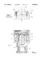
- FIG. 1is a sectional view of a prior art piezo probe with a delay line/delay block attached.
- FIG. 2is a longitudinal sectional view of a piezo probe encased in polymer and protected by a cooling chamber (heat sink) of coolant and a high temperature elastomer contact plate or plastic tip that is actually in contact with the heated surface.
- a cooling chamberheat sink
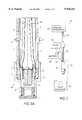
- FIG. 2Ais a longitudinal sectional view of the assembled invention.
- FIG. 3is a schematic drawing of the complete cooling system, including the coolant reservoir, coolant tubing, coolant pump, and control system.
- FIG. 1depicts a known piezo probe (50).
- This probecomprises primarily a transducer component (52) with active piezoelectric element (54).
- the transducer component (52)is held in abutting contact with a delay block (56) as by screws (58).
- NDTnon-destructive testing
- the delay blockprovides a temperature gradient so that the probe can remain on the surface a bit longer.
- FIG. 2Aillustrates an improved high temperature ultrasonic (UT) cooling chamber probe (20) manufactured from elastomer bar stock. Other embodiments allow it be molded or extruded material from various plastics or metallic materials.
- a contact plate, or tip (1)is made from a high temperature elastomer such as but not limited to PTFE. It may be screwed or otherwise connected into a body (2) as by threads (1a) and is sacrificial.
- An internal adapter (3)is manufactured from any olefin or thermosetting machinable plastic or metal.
- a piezo transducer (4)can either be machined into or screwed or otherwise connected with the adapter (3), depending on the type of transducer (4) employed.
- coolant taps or holes (5)are drilled into the adapter (3) with connections (6) to cooling tubes (7). Coolant from a reservoir source, as shown in FIG. 3, is circulated through the cooling chamber (heat sink) (8).
- a tubular handle (9)is incorporated. The handle (9) also serves as a conduit to house the tubing (7) and wiring (10) and (11) coming out of the probe, shown in FIG. 2.
- a switch (12)controls a pump (26) to circulate the coolant.
- the portable pump system shown in FIG. 3is included as an embodiment of the invention.
- the design of the portable pumping systemwill vary and the drawing of FIG. 3 does not limit the invention to a particular design.
- a bubble type level (13)is used to assist the operator in obtaining vertical alignment for the invention.
- FIG. 3depicts a pumping system (21) that circulates coolant through and around the piezo tube.
- the pumping systemconsists of a coolant reservoir (22) which holds coolant.
- Inlet and outlet tubing (24)goes to the coolant pump (26).
- Wiring (28)comes from the switch (12) to control the on/off of the pump (26).
- Coolant tubing (30)transports coolant in and out of the high temperature piezo probe cooling chamber (8).
- the systemfurther includes (UT) lead wire (32) coming out of high temperature piezo probe (36) going to a (UT) flaw detector (34).
- a battery (38)powers the pump through wiring (40).
Landscapes
- Health & Medical Sciences (AREA)
- Life Sciences & Earth Sciences (AREA)
- Physics & Mathematics (AREA)
- General Health & Medical Sciences (AREA)
- Pathology (AREA)
- Immunology (AREA)
- General Physics & Mathematics (AREA)
- Engineering & Computer Science (AREA)
- Biochemistry (AREA)
- Analytical Chemistry (AREA)
- Chemical & Material Sciences (AREA)
- Radiology & Medical Imaging (AREA)
- Heart & Thoracic Surgery (AREA)
- Animal Behavior & Ethology (AREA)
- Molecular Biology (AREA)
- Public Health (AREA)
- Veterinary Medicine (AREA)
- Medical Informatics (AREA)
- Surgery (AREA)
- Biomedical Technology (AREA)
- Nuclear Medicine, Radiotherapy & Molecular Imaging (AREA)
- Biophysics (AREA)
- Acoustics & Sound (AREA)
- Multimedia (AREA)
- Investigating Or Analyzing Materials By The Use Of Ultrasonic Waves (AREA)
Abstract
Description
The present invention relates to an ultrasonic piezo transducer/probe and the cooling chamber (heat sink) that will allow liquid coolant to be circulated around or through the piezo transducer/probe in high temperature applications, for the purpose of preventing damage to the piezo/probe at elevated temperatures.
Piezo ultrasound devises provide ultrasonic emissions to measure the thickness of materials, particularly metal. High temperature causes these electronic devises to become erratic and unreliable.
At present it is generally necessary to protect the piezo probe by using delay lines or delay blocks, which are devices that allow the ultrasonic probe to be in contact with the elevated temperature surface material for a longer period of time.
In practice, the probes are not held on the elevated temperature surface for more than a few seconds before they heat up and become erratic or are damaged. Since these are hand held devices, the operator cannot hold his hand steady and in place long enough for an accurate reading to be made.
On repeated contacts on the elevated temperature surface, the piezo probe becomes so over heated that its readings are not correct. Therefore, this method of measuring on a elevated temperature surface is not reliable or safe.
The present invention protects the unltrasonic testing (UT) piezo transducer/probe from high temperature failure and allows the operator to properly operate the instrument. The piezo transducer/probe is protected by a layer of high temperature elastomer or plastic. The piezo transducer/probe is immersed or surrounded in a coolant which is contained in a cooling chamber (heat sink) containing liquid or gas coolant, which may be circulated by a pumping system.
The piezo probe is maintained at a temperature not exceeding that of the cooling chamber (heat sink) liquid. The heat imposed on the probe is substantially reduced to a level consistent with the working temperature design of the instrument. The invention by design allows the operator's hands to be positioned away from the heat source.
For a more complete understanding of the present invention, and for the further details and advantages thereof, reference is now made to the following detailed description taken in conjunction with accompanying drawings in which:
FIG. 1 is a sectional view of a prior art piezo probe with a delay line/delay block attached.
FIG. 2 is a longitudinal sectional view of a piezo probe encased in polymer and protected by a cooling chamber (heat sink) of coolant and a high temperature elastomer contact plate or plastic tip that is actually in contact with the heated surface.
FIG. 2A is a longitudinal sectional view of the assembled invention.
FIG. 3 is a schematic drawing of the complete cooling system, including the coolant reservoir, coolant tubing, coolant pump, and control system.
FIG. 1 depicts a known piezo probe (50). This probe comprises primarily a transducer component (52) with active piezoelectric element (54). The transducer component (52) is held in abutting contact with a delay block (56) as by screws (58). As the probe (50) is brought in contact with an object surface for non-destructive testing (NDT), the delay block provides a temperature gradient so that the probe can remain on the surface a bit longer.
FIG. 2A illustrates an improved high temperature ultrasonic (UT) cooling chamber probe (20) manufactured from elastomer bar stock. Other embodiments allow it be molded or extruded material from various plastics or metallic materials. A contact plate, or tip (1) is made from a high temperature elastomer such as but not limited to PTFE. It may be screwed or otherwise connected into a body (2) as by threads (1a) and is sacrificial. An internal adapter (3) is manufactured from any olefin or thermosetting machinable plastic or metal. A piezo transducer (4) can either be machined into or screwed or otherwise connected with the adapter (3), depending on the type of transducer (4) employed.
In this embodiment, coolant taps or holes (5) are drilled into the adapter (3) with connections (6) to cooling tubes (7). Coolant from a reservoir source, as shown in FIG. 3, is circulated through the cooling chamber (heat sink) (8). A tubular handle (9) is incorporated. The handle (9) also serves as a conduit to house the tubing (7) and wiring (10) and (11) coming out of the probe, shown in FIG. 2. A switch (12) controls a pump (26) to circulate the coolant.
The portable pump system shown in FIG. 3 is included as an embodiment of the invention. The design of the portable pumping system will vary and the drawing of FIG. 3 does not limit the invention to a particular design.
A bubble type level (13) is used to assist the operator in obtaining vertical alignment for the invention.
FIG. 3 depicts a pumping system (21) that circulates coolant through and around the piezo tube. The pumping system consists of a coolant reservoir (22) which holds coolant. Inlet and outlet tubing (24) goes to the coolant pump (26). Wiring (28) comes from the switch (12) to control the on/off of the pump (26). Coolant tubing (30) transports coolant in and out of the high temperature piezo probe cooling chamber (8). The system further includes (UT) lead wire (32) coming out of high temperature piezo probe (36) going to a (UT) flaw detector (34). A battery (38) powers the pump through wiring (40).
Claims (12)
1. An ultrasonic probe for performing non-destructive testing of a hot, solid material, the probe comprising:
a. a substantially cylindrical body defining a lower end and an upper end;
b. a contact plate enclosing the lower end of the body, the contact plate adapted for abutting contact with the material under test;
c. an internal adapter within the upper end of the body, the contact plate and the internal adapter defining a volume with the body;
d. inlet and outlet coolant penetrations through the internal adapter for circulating coolant through the volume; and
e. a piezo transducer in the internal adapter in a spaced apart relationship from the contact plate so that a portion of the volume lies between the piezo transducer and the contact plate.
2. The probe of claim 1, further comprising a source of coolant coupled to the inlet.
3. The probe of claim 2, further comprising a receiver coupled to the outlet.
4. The probe of claim 3, further comprising a pump to pump coolant from the source into the inlet and out the outlet so that coolant flows between the piezo transducer and the contact plate.
5. The probe of claim 4, further comprising a tubular handle joined to and extending from the body.
6. The probe of claim 5, further comprising an electrical switch on the handle and electrically coupled to the pump to control the actuation of the pump.
7. The probe of claim 5, further comprising level indicating means on the handle.
8. The probe of claim 1, wherein the contact plate is formed of a high temperature elastomer.
9. The probe of claim 1, wherein the probe is portable.
10. A method of inducing an ultrasonic signal onto a high temperature solid surface with an ultrasonic probe, comprising the steps of:
a. placing a contact plate in contact with the surface, wherein said contact plate encloses a lower end of a cylindrical body;
b. inducing an ultrasonic signal from a signal source, wherein said signal source is within an internal adapter enclosing an upper end of said cylindrical body; and
c. circulating a coolant through a volume defined by said contact plate and said adapter with said cylindrical body, such that a portion of the volume lies between said signal source and said contact plate.
11. The method of claim 10, wherein the contact plate and the signal source are mounted to a common body and the body is coupled to a handle extending from the body.
12. The method of claim 11, further comprising the step of verifying the orientation of the probe with a level detector on the handle.
Priority Applications (1)
| Application Number | Priority Date | Filing Date | Title |
|---|---|---|---|
| US09/076,985US5936163A (en) | 1998-05-13 | 1998-05-13 | Portable high temperature ultrasonic testing (UT) piezo probe with cooling apparatus |
Applications Claiming Priority (1)
| Application Number | Priority Date | Filing Date | Title |
|---|---|---|---|
| US09/076,985US5936163A (en) | 1998-05-13 | 1998-05-13 | Portable high temperature ultrasonic testing (UT) piezo probe with cooling apparatus |
Publications (1)
| Publication Number | Publication Date |
|---|---|
| US5936163Atrue US5936163A (en) | 1999-08-10 |
Family
ID=22135432
Family Applications (1)
| Application Number | Title | Priority Date | Filing Date |
|---|---|---|---|
| US09/076,985Expired - Fee RelatedUS5936163A (en) | 1998-05-13 | 1998-05-13 | Portable high temperature ultrasonic testing (UT) piezo probe with cooling apparatus |
Country Status (1)
| Country | Link |
|---|---|
| US (1) | US5936163A (en) |
Cited By (14)
| Publication number | Priority date | Publication date | Assignee | Title |
|---|---|---|---|---|
| US20030072127A1 (en)* | 2001-07-17 | 2003-04-17 | Art Zias | Micro-electromechanical sensor |
| DE10254894B3 (en)* | 2002-11-20 | 2004-05-27 | Dr. Hielscher Gmbh | Cooling device for ultrasonic transducers has cooling fluid passed through flow channels at defined pressure for reducing or preventing cavitation |
| DE10350021B3 (en)* | 2003-10-27 | 2005-05-25 | Sick Engineering Gmbh | Ultrasonic probe, e.g. for measuring flowing media, has coolant feed channel enclosing transducer and fed out to inside of sound surface; cooling fluid flows round transducer, is diverted into outflow channel immediately after sound surface |
| US6959589B1 (en)* | 2003-10-03 | 2005-11-01 | The United States Of America As Represented By The United States Department Of Energy | Ultrasound analysis of slurries |
| US20060025683A1 (en)* | 2004-07-30 | 2006-02-02 | Ahof Biophysical Systems Inc. | Hand-held imaging probe for treatment of states of low blood perfusion |
| US20080275371A1 (en)* | 2003-09-04 | 2008-11-06 | Ahof Biophysical Systems Inc. | Vibrator with a plurality of contact nodes for treatment of myocardial ischemia |
| US20080275343A1 (en)* | 2003-09-04 | 2008-11-06 | Ahof Biophysical Systems Inc. | Percussion assisted angiogenesis |
| US20090069728A1 (en)* | 2004-07-30 | 2009-03-12 | Andrew Kenneth Hoffmann | Randomic vibration for treatment of blood flow disorders |
| US20090270773A1 (en)* | 2003-09-04 | 2009-10-29 | Ahof Biophysical Systems Inc. | Automatically adjusting contact node for multiple rib space engagement |
| US8870796B2 (en) | 2003-09-04 | 2014-10-28 | Ahof Biophysical Systems Inc. | Vibration method for clearing acute arterial thrombotic occlusions in the emergency treatment of heart attack and stroke |
| DE102015000207A1 (en)* | 2015-01-15 | 2016-07-21 | Hella Kgaa Hueck & Co. | Method and device for detecting a structure-borne sound signal, in particular for detecting a structure-borne noise signal triggered by a damage event on a component to be monitored |
| AT523023A1 (en)* | 2019-09-30 | 2021-04-15 | Johannes Kepler Univ | COOLED ULTRASONIC SENSOR |
| US11620973B2 (en) | 2018-11-05 | 2023-04-04 | X-wave Innovations, Inc. | High tolerance ultrasonic transducer |
| US12290837B2 (en) | 2019-07-31 | 2025-05-06 | X-wave Innovations, Inc. | Radiation and high-temperature tolerant piezoelectric ultrasonic contact transducer with mounting assembly |
Citations (12)
| Publication number | Priority date | Publication date | Assignee | Title |
|---|---|---|---|---|
| US3555297A (en)* | 1969-10-13 | 1971-01-12 | Eastman Kodak Co | Cooled ultrasonic transducer |
| US3979946A (en)* | 1974-06-10 | 1976-09-14 | The Steel Company Of Canada, Limited | Ultrasonic plate inspection system |
| US4509360A (en)* | 1983-06-24 | 1985-04-09 | Massachusetts Institute Of Technology | On-line measurement of fluid mixtures |
| US4526038A (en)* | 1984-02-13 | 1985-07-02 | United States Steel Corporation | Cross-flow ultrasonic transducer head |
| US4567770A (en)* | 1983-03-21 | 1986-02-04 | Sonic Instruments Inc. | Ultrasonic transducer apparatus and method for high temperature measurements |
| US4887460A (en)* | 1989-01-19 | 1989-12-19 | Nelson Industries, Inc. | Apparatus for measuring the vibrational characteristics of a muffler |
| US5195373A (en)* | 1991-04-17 | 1993-03-23 | Southwest Research Institute | Ultrasonic transducer for extreme temperature environments |
| US5450753A (en)* | 1992-12-14 | 1995-09-19 | Vought Aircraft Company | Method and apparatus for cooling sensors in high temperature environments |
| US5546809A (en)* | 1994-12-12 | 1996-08-20 | Houston Industries Incorporated | Vibration monitor mounting block |
| US5585565A (en)* | 1993-07-06 | 1996-12-17 | Tuboscope Vetco International, Inc. | Method for the ultrasonic inspection of pipe and tubing and a transducer assembly for use therewith |
| US5708209A (en)* | 1996-08-27 | 1998-01-13 | Aluminum Company Of America | Apparatus and method for ultrasonic particle detection in molten metal |
| US5821418A (en)* | 1996-04-28 | 1998-10-13 | The United States Of America As Represented By The Secretary Of The Navy | Cooled fixture for high temperature accelerometer measurements |
- 1998
- 1998-05-13USUS09/076,985patent/US5936163A/ennot_activeExpired - Fee Related
Patent Citations (12)
| Publication number | Priority date | Publication date | Assignee | Title |
|---|---|---|---|---|
| US3555297A (en)* | 1969-10-13 | 1971-01-12 | Eastman Kodak Co | Cooled ultrasonic transducer |
| US3979946A (en)* | 1974-06-10 | 1976-09-14 | The Steel Company Of Canada, Limited | Ultrasonic plate inspection system |
| US4567770A (en)* | 1983-03-21 | 1986-02-04 | Sonic Instruments Inc. | Ultrasonic transducer apparatus and method for high temperature measurements |
| US4509360A (en)* | 1983-06-24 | 1985-04-09 | Massachusetts Institute Of Technology | On-line measurement of fluid mixtures |
| US4526038A (en)* | 1984-02-13 | 1985-07-02 | United States Steel Corporation | Cross-flow ultrasonic transducer head |
| US4887460A (en)* | 1989-01-19 | 1989-12-19 | Nelson Industries, Inc. | Apparatus for measuring the vibrational characteristics of a muffler |
| US5195373A (en)* | 1991-04-17 | 1993-03-23 | Southwest Research Institute | Ultrasonic transducer for extreme temperature environments |
| US5450753A (en)* | 1992-12-14 | 1995-09-19 | Vought Aircraft Company | Method and apparatus for cooling sensors in high temperature environments |
| US5585565A (en)* | 1993-07-06 | 1996-12-17 | Tuboscope Vetco International, Inc. | Method for the ultrasonic inspection of pipe and tubing and a transducer assembly for use therewith |
| US5546809A (en)* | 1994-12-12 | 1996-08-20 | Houston Industries Incorporated | Vibration monitor mounting block |
| US5821418A (en)* | 1996-04-28 | 1998-10-13 | The United States Of America As Represented By The Secretary Of The Navy | Cooled fixture for high temperature accelerometer measurements |
| US5708209A (en)* | 1996-08-27 | 1998-01-13 | Aluminum Company Of America | Apparatus and method for ultrasonic particle detection in molten metal |
Cited By (24)
| Publication number | Priority date | Publication date | Assignee | Title |
|---|---|---|---|---|
| US7047814B2 (en) | 2001-07-17 | 2006-05-23 | Redwood Microsystems, Inc. | Micro-electromechanical sensor |
| US20030072127A1 (en)* | 2001-07-17 | 2003-04-17 | Art Zias | Micro-electromechanical sensor |
| DE10254894B3 (en)* | 2002-11-20 | 2004-05-27 | Dr. Hielscher Gmbh | Cooling device for ultrasonic transducers has cooling fluid passed through flow channels at defined pressure for reducing or preventing cavitation |
| WO2004047073A2 (en) | 2002-11-20 | 2004-06-03 | Dr. Hielscher Gmbh | Method and device for cooling ultrasonic transducers |
| US8004158B2 (en) | 2002-11-20 | 2011-08-23 | Dr. Hielscher Gmbh | Method and device for cooling ultrasonic transducers |
| US20060126884A1 (en)* | 2002-11-20 | 2006-06-15 | Harald Hielscher | Method and device for cooling ultrasonic transducers |
| US20090270773A1 (en)* | 2003-09-04 | 2009-10-29 | Ahof Biophysical Systems Inc. | Automatically adjusting contact node for multiple rib space engagement |
| US8734368B2 (en) | 2003-09-04 | 2014-05-27 | Simon Fraser University | Percussion assisted angiogenesis |
| US20080275371A1 (en)* | 2003-09-04 | 2008-11-06 | Ahof Biophysical Systems Inc. | Vibrator with a plurality of contact nodes for treatment of myocardial ischemia |
| US20080275343A1 (en)* | 2003-09-04 | 2008-11-06 | Ahof Biophysical Systems Inc. | Percussion assisted angiogenesis |
| US20080287793A1 (en)* | 2003-09-04 | 2008-11-20 | Andrew Kenneth Hoffmann | Low frequency vibration assisted blood perfusion emergency system |
| US8870796B2 (en) | 2003-09-04 | 2014-10-28 | Ahof Biophysical Systems Inc. | Vibration method for clearing acute arterial thrombotic occlusions in the emergency treatment of heart attack and stroke |
| US8079968B2 (en) | 2003-09-04 | 2011-12-20 | Ahof Biophysical Systems Inc. | Vibrator with a plurality of contact nodes for treatment of myocardial ischemia |
| US8721573B2 (en) | 2003-09-04 | 2014-05-13 | Simon Fraser University | Automatically adjusting contact node for multiple rib space engagement |
| US6959589B1 (en)* | 2003-10-03 | 2005-11-01 | The United States Of America As Represented By The United States Department Of Energy | Ultrasound analysis of slurries |
| DE10350021B3 (en)* | 2003-10-27 | 2005-05-25 | Sick Engineering Gmbh | Ultrasonic probe, e.g. for measuring flowing media, has coolant feed channel enclosing transducer and fed out to inside of sound surface; cooling fluid flows round transducer, is diverted into outflow channel immediately after sound surface |
| US20090069728A1 (en)* | 2004-07-30 | 2009-03-12 | Andrew Kenneth Hoffmann | Randomic vibration for treatment of blood flow disorders |
| US20060025683A1 (en)* | 2004-07-30 | 2006-02-02 | Ahof Biophysical Systems Inc. | Hand-held imaging probe for treatment of states of low blood perfusion |
| DE102015000207A1 (en)* | 2015-01-15 | 2016-07-21 | Hella Kgaa Hueck & Co. | Method and device for detecting a structure-borne sound signal, in particular for detecting a structure-borne noise signal triggered by a damage event on a component to be monitored |
| US10067095B2 (en) | 2015-01-15 | 2018-09-04 | Hella Kgaa Hueck & Co. | Method and device for detecting a structure-borne sound signal, in particular for detecting a structure-borne sound signal triggered by an occurrence of damage on a component to be monitored |
| US11620973B2 (en) | 2018-11-05 | 2023-04-04 | X-wave Innovations, Inc. | High tolerance ultrasonic transducer |
| US12290837B2 (en) | 2019-07-31 | 2025-05-06 | X-wave Innovations, Inc. | Radiation and high-temperature tolerant piezoelectric ultrasonic contact transducer with mounting assembly |
| AT523023A1 (en)* | 2019-09-30 | 2021-04-15 | Johannes Kepler Univ | COOLED ULTRASONIC SENSOR |
| AT523023B1 (en)* | 2019-09-30 | 2023-05-15 | Johannes Kepler Univ | COOLED ULTRASONIC SENSOR |
Similar Documents
| Publication | Publication Date | Title |
|---|---|---|
| US5936163A (en) | Portable high temperature ultrasonic testing (UT) piezo probe with cooling apparatus | |
| US4098662A (en) | Corrosion probe for use in measuring corrosion rate under specified heat transfer conditions | |
| JPH08254512A (en) | Method and apparatus for evaluating thermal impedance of packaging semiconductor components | |
| US10989610B2 (en) | Adjustable spring loaded adapter for temperature sensor | |
| KR102485072B1 (en) | Gas sensor probe for measuring dissolved gas of transformer | |
| KR101196407B1 (en) | Method for measuring local flow rates in liquid melts | |
| KR20200071684A (en) | Fluid Sensor Assembly | |
| US4441358A (en) | Automated ultrasonic solution viscometer | |
| US4479726A (en) | Apparatus for calibrating surface temperature measuring devices | |
| US3416356A (en) | Dew point hygrometer | |
| EP0686846A2 (en) | Quench system cooling effectiveness meter and method of operating same | |
| US7563022B2 (en) | Methods and apparatus for inspecting reactor pressure tubes | |
| US6725717B2 (en) | Non-intrusive locating of a blockage in a pipeline | |
| US3443797A (en) | Instrument for measuring cavitation intensity in a liquid | |
| US2982930A (en) | Corrosion probe with encased reference specimen | |
| AU635257B2 (en) | Indicating device | |
| Bunt et al. | Developing a Low-Cost Instrumented Heat Transfer Apparatus for Measuring Thermal Conductivity Using Steady-State Methods | |
| US4276775A (en) | Temperature sensor for measuring the temperature of a part of an automobile | |
| WO2001036959A1 (en) | Apparatus and method for measuring a property of a liquid | |
| CN223412786U (en) | Liquid level detection device, container equipment and cable polarization analyzer | |
| JP2936231B2 (en) | Internal defect detection device for rubber and plastic materials | |
| CN223320141U (en) | A heating system for ultrasonic fatigue test specimens | |
| JPS61128127A (en) | Supersonic wave pressure intensity measurement and apparatus therefor | |
| EP4481343A1 (en) | Method for calibrating a surface temperature sensing system | |
| RU2691770C1 (en) | Device for investigating properties of a tube of a coordinate particle detector |
Legal Events
| Date | Code | Title | Description |
|---|---|---|---|
| FPAY | Fee payment | Year of fee payment:4 | |
| FEPP | Fee payment procedure | Free format text:PAYOR NUMBER ASSIGNED (ORIGINAL EVENT CODE: ASPN); ENTITY STATUS OF PATENT OWNER: SMALL ENTITY | |
| REMI | Maintenance fee reminder mailed | ||
| LAPS | Lapse for failure to pay maintenance fees | ||
| STCH | Information on status: patent discontinuation | Free format text:PATENT EXPIRED DUE TO NONPAYMENT OF MAINTENANCE FEES UNDER 37 CFR 1.362 | |
| FP | Lapsed due to failure to pay maintenance fee | Effective date:20070810 |