US5935293A - Fast quench reactor method - Google Patents
Fast quench reactor methodDownload PDFInfo
- Publication number
- US5935293A US5935293AUS09/076,922US7692298AUS5935293AUS 5935293 AUS5935293 AUS 5935293AUS 7692298 AUS7692298 AUS 7692298AUS 5935293 AUS5935293 AUS 5935293A
- Authority
- US
- United States
- Prior art keywords
- gas
- nozzle
- stream
- reactant
- plasma
- Prior art date
- Legal status (The legal status is an assumption and is not a legal conclusion. Google has not performed a legal analysis and makes no representation as to the accuracy of the status listed.)
- Expired - Lifetime
Links
- 238000000034methodMethods0.000titleclaimsabstractdescription93
- 238000010791quenchingMethods0.000titleabstractdescription61
- 238000006243chemical reactionMethods0.000claimsabstractdescription145
- 239000000376reactantSubstances0.000claimsabstractdescription81
- 239000007795chemical reaction productSubstances0.000claimsabstractdescription50
- 238000010438heat treatmentMethods0.000claimsabstractdescription16
- 229910001507metal halideInorganic materials0.000claimsabstractdescription13
- 150000005309metal halidesChemical class0.000claimsabstractdescription13
- 239000007789gasSubstances0.000claimsdescription202
- 239000010936titaniumSubstances0.000claimsdescription67
- RTAQQCXQSZGOHL-UHFFFAOYSA-NTitaniumChemical group[Ti]RTAQQCXQSZGOHL-UHFFFAOYSA-N0.000claimsdescription63
- 229910052739hydrogenInorganic materials0.000claimsdescription62
- 229910052719titaniumInorganic materials0.000claimsdescription60
- 239000001257hydrogenSubstances0.000claimsdescription58
- UFHFLCQGNIYNRP-UHFFFAOYSA-NHydrogenChemical compound[H][H]UFHFLCQGNIYNRP-UHFFFAOYSA-N0.000claimsdescription56
- XJDNKRIXUMDJCW-UHFFFAOYSA-Jtitanium tetrachlorideChemical groupCl[Ti](Cl)(Cl)ClXJDNKRIXUMDJCW-UHFFFAOYSA-J0.000claimsdescription46
- 239000000843powderSubstances0.000claimsdescription41
- 229910052751metalInorganic materials0.000claimsdescription40
- 239000002184metalSubstances0.000claimsdescription40
- 239000007787solidSubstances0.000claimsdescription32
- 238000004519manufacturing processMethods0.000claimsdescription28
- 238000001816coolingMethods0.000claimsdescription26
- 239000007788liquidSubstances0.000claimsdescription26
- 238000002347injectionMethods0.000claimsdescription24
- 239000007924injectionSubstances0.000claimsdescription24
- 239000000203mixtureSubstances0.000claimsdescription22
- 239000002245particleSubstances0.000claimsdescription19
- 238000002156mixingMethods0.000claimsdescription15
- 230000000694effectsEffects0.000claimsdescription13
- SANRKQGLYCLAFE-UHFFFAOYSA-Huranium hexafluorideChemical groupF[U](F)(F)(F)(F)FSANRKQGLYCLAFE-UHFFFAOYSA-H0.000claimsdescription12
- 229910052770UraniumInorganic materials0.000claimsdescription10
- 239000000919ceramicSubstances0.000claimsdescription9
- JFALSRSLKYAFGM-UHFFFAOYSA-Nuranium(0)Chemical group[U]JFALSRSLKYAFGM-UHFFFAOYSA-N0.000claimsdescription9
- LEONUFNNVUYDNQ-UHFFFAOYSA-Nvanadium atomChemical group[V]LEONUFNNVUYDNQ-UHFFFAOYSA-N0.000claimsdescription9
- 229910052720vanadiumInorganic materials0.000claimsdescription8
- XAGFODPZIPBFFR-UHFFFAOYSA-NaluminiumChemical group[Al]XAGFODPZIPBFFR-UHFFFAOYSA-N0.000claimsdescription7
- -1dropletsSubstances0.000claimsdescription5
- 229910021552Vanadium(IV) chlorideInorganic materials0.000claimsdescription4
- VSCWAEJMTAWNJL-UHFFFAOYSA-Kaluminium trichlorideChemical groupCl[Al](Cl)ClVSCWAEJMTAWNJL-UHFFFAOYSA-K0.000claimsdescription4
- 239000002131composite materialSubstances0.000claimsdescription4
- 238000012546transferMethods0.000claimsdescription4
- JTJFQBNJBPPZRI-UHFFFAOYSA-Jvanadium tetrachlorideChemical groupCl[V](Cl)(Cl)ClJTJFQBNJBPPZRI-UHFFFAOYSA-J0.000claimsdescription4
- 229910000756V alloyInorganic materials0.000claimsdescription3
- 150000003609titanium compoundsChemical class0.000claims3
- QDMRQDKMCNPQQH-UHFFFAOYSA-NboranylidynetitaniumChemical group[B].[Ti]QDMRQDKMCNPQQH-UHFFFAOYSA-N0.000claims1
- PFSXARRIPPWGNC-UHFFFAOYSA-Jhexafluorotitanium(2-);hydronChemical group[H+].[H+].[F-].[F-].[F-].[F-].[F-].[F-].[Ti+4]PFSXARRIPPWGNC-UHFFFAOYSA-J0.000claims1
- 125000004435hydrogen atomChemical group[H]*0.000claims1
- GFNGCDBZVSLSFT-UHFFFAOYSA-Ntitanium vanadiumChemical group[Ti].[V]GFNGCDBZVSLSFT-UHFFFAOYSA-N0.000claims1
- FAQYAMRNWDIXMY-UHFFFAOYSA-NtrichloroboraneChemical compoundClB(Cl)ClFAQYAMRNWDIXMY-UHFFFAOYSA-N0.000claims1
- 230000008569processEffects0.000abstractdescription56
- 210000002381plasmaAnatomy0.000description124
- VNWKTOKETHGBQD-UHFFFAOYSA-NmethaneChemical compoundCVNWKTOKETHGBQD-UHFFFAOYSA-N0.000description85
- XKRFYHLGVUSROY-UHFFFAOYSA-NArgonChemical compound[Ar]XKRFYHLGVUSROY-UHFFFAOYSA-N0.000description58
- HSFWRNGVRCDJHI-UHFFFAOYSA-Nalpha-acetyleneNatural productsC#CHSFWRNGVRCDJHI-UHFFFAOYSA-N0.000description48
- 125000002534ethynyl groupChemical group[H]C#C*0.000description48
- 239000000047productSubstances0.000description36
- 229910052786argonInorganic materials0.000description32
- OKTJSMMVPCPJKN-UHFFFAOYSA-NCarbonChemical compound[C]OKTJSMMVPCPJKN-UHFFFAOYSA-N0.000description31
- 229910052799carbonInorganic materials0.000description26
- 230000015572biosynthetic processEffects0.000description23
- GWEVSGVZZGPLCZ-UHFFFAOYSA-NTitan oxideChemical compoundO=[Ti]=OGWEVSGVZZGPLCZ-UHFFFAOYSA-N0.000description20
- 238000005755formation reactionMethods0.000description20
- 230000006911nucleationEffects0.000description20
- 238000010899nucleationMethods0.000description20
- 239000000463materialSubstances0.000description19
- 230000000171quenching effectEffects0.000description16
- 229930195733hydrocarbonNatural products0.000description14
- 150000002430hydrocarbonsChemical class0.000description13
- 239000003345natural gasSubstances0.000description13
- VEXZGXHMUGYJMC-UHFFFAOYSA-NHydrochloric acidChemical compoundClVEXZGXHMUGYJMC-UHFFFAOYSA-N0.000description12
- 229910000041hydrogen chlorideInorganic materials0.000description12
- IXCSERBJSXMMFS-UHFFFAOYSA-Nhydrogen chlorideSubstancesCl.ClIXCSERBJSXMMFS-UHFFFAOYSA-N0.000description12
- 230000009467reductionEffects0.000description12
- IJGRMHOSHXDMSA-UHFFFAOYSA-NAtomic nitrogenChemical compoundN#NIJGRMHOSHXDMSA-UHFFFAOYSA-N0.000description11
- 150000002431hydrogenChemical class0.000description11
- 230000001965increasing effectEffects0.000description11
- 239000000126substanceSubstances0.000description11
- QVGXLLKOCUKJST-UHFFFAOYSA-Natomic oxygenChemical compound[O]QVGXLLKOCUKJST-UHFFFAOYSA-N0.000description9
- 238000002474experimental methodMethods0.000description9
- 239000001301oxygenSubstances0.000description9
- 229910052760oxygenInorganic materials0.000description9
- 229910001069Ti alloyInorganic materials0.000description8
- 239000006227byproductSubstances0.000description8
- 238000004364calculation methodMethods0.000description8
- 238000005516engineering processMethods0.000description8
- 230000006870functionEffects0.000description8
- 239000004215Carbon black (E152)Substances0.000description7
- PXHVJJICTQNCMI-UHFFFAOYSA-NNickelChemical compound[Ni]PXHVJJICTQNCMI-UHFFFAOYSA-N0.000description7
- 238000011021bench scale processMethods0.000description7
- 239000012159carrier gasSubstances0.000description7
- 150000001875compoundsChemical class0.000description7
- 238000009833condensationMethods0.000description7
- 230000005494condensationEffects0.000description7
- 238000000354decomposition reactionMethods0.000description7
- 230000007423decreaseEffects0.000description7
- 239000012530fluidSubstances0.000description7
- 230000033001locomotionEffects0.000description7
- 239000012071phaseSubstances0.000description7
- 230000008859changeEffects0.000description6
- 239000000460chlorineSubstances0.000description6
- 229910052801chlorineInorganic materials0.000description6
- 230000007797corrosionEffects0.000description6
- 238000005260corrosionMethods0.000description6
- 238000013461designMethods0.000description6
- 238000000926separation methodMethods0.000description6
- 238000012360testing methodMethods0.000description6
- XLYOFNOQVPJJNP-UHFFFAOYSA-NwaterSubstancesOXLYOFNOQVPJJNP-UHFFFAOYSA-N0.000description6
- VGGSQFUCUMXWEO-UHFFFAOYSA-NEtheneChemical compoundC=CVGGSQFUCUMXWEO-UHFFFAOYSA-N0.000description5
- 239000005977EthyleneSubstances0.000description5
- YCKRFDGAMUMZLT-UHFFFAOYSA-NFluorine atomChemical group[F]YCKRFDGAMUMZLT-UHFFFAOYSA-N0.000description5
- 229910052782aluminiumInorganic materials0.000description5
- 238000011161developmentMethods0.000description5
- 239000012535impuritySubstances0.000description5
- 150000002739metalsChemical class0.000description5
- 229910052757nitrogenInorganic materials0.000description5
- 238000004663powder metallurgyMethods0.000description5
- 239000004408titanium dioxideSubstances0.000description5
- ZAMOUSCENKQFHK-UHFFFAOYSA-NChlorine atomChemical compound[Cl]ZAMOUSCENKQFHK-UHFFFAOYSA-N0.000description4
- ATUOYWHBWRKTHZ-UHFFFAOYSA-NPropaneChemical compoundCCCATUOYWHBWRKTHZ-UHFFFAOYSA-N0.000description4
- 239000006230acetylene blackSubstances0.000description4
- 150000001336alkenesChemical class0.000description4
- 229910045601alloyInorganic materials0.000description4
- 239000000956alloySubstances0.000description4
- 239000006229carbon blackSubstances0.000description4
- 238000006731degradation reactionMethods0.000description4
- 238000010891electric arcMethods0.000description4
- 229910052734heliumInorganic materials0.000description4
- 238000001556precipitationMethods0.000description4
- 238000000197pyrolysisMethods0.000description4
- 230000002829reductive effectEffects0.000description4
- 229910052721tungstenInorganic materials0.000description4
- 239000010937tungstenSubstances0.000description4
- RYGMFSIKBFXOCR-UHFFFAOYSA-NCopperChemical compound[Cu]RYGMFSIKBFXOCR-UHFFFAOYSA-N0.000description3
- PXGOKWXKJXAPGV-UHFFFAOYSA-NFluorineChemical compoundFFPXGOKWXKJXAPGV-UHFFFAOYSA-N0.000description3
- 230000008901benefitEffects0.000description3
- 230000015556catabolic processEffects0.000description3
- 150000001805chlorine compoundsChemical class0.000description3
- 239000002826coolantSubstances0.000description3
- 229910052802copperInorganic materials0.000description3
- 239000010949copperSubstances0.000description3
- 239000011737fluorineSubstances0.000description3
- 229910052731fluorineInorganic materials0.000description3
- 238000010574gas phase reactionMethods0.000description3
- 239000011777magnesiumSubstances0.000description3
- 229910052749magnesiumInorganic materials0.000description3
- 230000003647oxidationEffects0.000description3
- 238000007254oxidation reactionMethods0.000description3
- 230000036961partial effectEffects0.000description3
- 238000000746purificationMethods0.000description3
- 239000002994raw materialSubstances0.000description3
- 239000011734sodiumSubstances0.000description3
- 229910052708sodiumInorganic materials0.000description3
- 239000010935stainless steelSubstances0.000description3
- 229910001220stainless steelInorganic materials0.000description3
- 238000003786synthesis reactionMethods0.000description3
- WFKWXMTUELFFGS-UHFFFAOYSA-NtungstenChemical compound[W]WFKWXMTUELFFGS-UHFFFAOYSA-N0.000description3
- 238000011144upstream manufacturingMethods0.000description3
- QGZKDVFQNNGYKY-UHFFFAOYSA-NAmmoniaChemical compoundNQGZKDVFQNNGYKY-UHFFFAOYSA-N0.000description2
- NLXLAEXVIDQMFP-UHFFFAOYSA-NAmmonia chlorideChemical compound[NH4+].[Cl-]NLXLAEXVIDQMFP-UHFFFAOYSA-N0.000description2
- CURLTUGMZLYLDI-UHFFFAOYSA-NCarbon dioxideChemical compoundO=C=OCURLTUGMZLYLDI-UHFFFAOYSA-N0.000description2
- UGFAIRIUMAVXCW-UHFFFAOYSA-NCarbon monoxideChemical compound[O+]#[C-]UGFAIRIUMAVXCW-UHFFFAOYSA-N0.000description2
- YZCKVEUIGOORGS-UHFFFAOYSA-NHydrogen atomChemical compound[H]YZCKVEUIGOORGS-UHFFFAOYSA-N0.000description2
- DGAQECJNVWCQMB-PUAWFVPOSA-MIlexoside XXIXChemical compoundC[C@@H]1CC[C@@]2(CC[C@@]3(C(=CC[C@H]4[C@]3(CC[C@@H]5[C@@]4(CC[C@@H](C5(C)C)OS(=O)(=O)[O-])C)C)[C@@H]2[C@]1(C)O)C)C(=O)O[C@H]6[C@@H]([C@H]([C@@H]([C@H](O6)CO)O)O)O.[Na+]DGAQECJNVWCQMB-PUAWFVPOSA-M0.000description2
- FYYHWMGAXLPEAU-UHFFFAOYSA-NMagnesiumChemical compound[Mg]FYYHWMGAXLPEAU-UHFFFAOYSA-N0.000description2
- 230000001133accelerationEffects0.000description2
- 125000004429atomChemical group0.000description2
- 238000009835boilingMethods0.000description2
- 229910002091carbon monoxideInorganic materials0.000description2
- 239000003054catalystSubstances0.000description2
- 229910010293ceramic materialInorganic materials0.000description2
- 239000003638chemical reducing agentSubstances0.000description2
- 125000001309chloro groupChemical groupCl*0.000description2
- 238000005056compactionMethods0.000description2
- 238000005336crackingMethods0.000description2
- 239000013078crystalSubstances0.000description2
- 238000010586diagramMethods0.000description2
- 238000005265energy consumptionMethods0.000description2
- 230000002349favourable effectEffects0.000description2
- 239000012467final productSubstances0.000description2
- 239000000446fuelSubstances0.000description2
- 239000001307heliumSubstances0.000description2
- SWQJXJOGLNCZEY-UHFFFAOYSA-Nhelium atomChemical compound[He]SWQJXJOGLNCZEY-UHFFFAOYSA-N0.000description2
- 230000001976improved effectEffects0.000description2
- 238000013383initial experimentMethods0.000description2
- 230000000977initiatory effectEffects0.000description2
- 229910000765intermetallicInorganic materials0.000description2
- 238000009533lab testMethods0.000description2
- 238000011031large-scale manufacturing processMethods0.000description2
- 230000007246mechanismEffects0.000description2
- 230000008018meltingEffects0.000description2
- 238000002844meltingMethods0.000description2
- 229910044991metal oxideInorganic materials0.000description2
- 150000004706metal oxidesChemical class0.000description2
- 238000012986modificationMethods0.000description2
- 230000004048modificationEffects0.000description2
- 230000007935neutral effectEffects0.000description2
- 229910052759nickelInorganic materials0.000description2
- 150000004767nitridesChemical class0.000description2
- 239000003921oilSubstances0.000description2
- 238000005457optimizationMethods0.000description2
- 230000001590oxidative effectEffects0.000description2
- 239000004033plasticSubstances0.000description2
- 229920003023plasticPolymers0.000description2
- 238000012545processingMethods0.000description2
- 239000001294propaneSubstances0.000description2
- 230000005855radiationEffects0.000description2
- 238000004064recyclingMethods0.000description2
- 238000003303reheatingMethods0.000description2
- 238000011160researchMethods0.000description2
- 238000007086side reactionMethods0.000description2
- 239000013589supplementSubstances0.000description2
- 239000011269tarSubstances0.000description2
- OGIDPMRJRNCKJF-UHFFFAOYSA-Ntitanium oxideInorganic materials[Ti]=OOGIDPMRJRNCKJF-UHFFFAOYSA-N0.000description2
- 229910017917NH4 ClInorganic materials0.000description1
- NPXOKRUENSOPAO-UHFFFAOYSA-NRaney nickelChemical compound[Al].[Ni]NPXOKRUENSOPAO-UHFFFAOYSA-N0.000description1
- XUIMIQQOPSSXEZ-UHFFFAOYSA-NSiliconChemical compound[Si]XUIMIQQOPSSXEZ-UHFFFAOYSA-N0.000description1
- 229910000831SteelInorganic materials0.000description1
- 229910021551Vanadium(III) chlorideInorganic materials0.000description1
- 238000002441X-ray diffractionMethods0.000description1
- OQPDWFJSZHWILH-UHFFFAOYSA-N[Al].[Al].[Al].[Ti]Chemical compound[Al].[Al].[Al].[Ti]OQPDWFJSZHWILH-UHFFFAOYSA-N0.000description1
- CVTZKFWZDBJAHE-UHFFFAOYSA-N[N].NChemical compound[N].NCVTZKFWZDBJAHE-UHFFFAOYSA-N0.000description1
- 238000002679ablationMethods0.000description1
- 150000001335aliphatic alkanesChemical class0.000description1
- 238000005275alloyingMethods0.000description1
- PNEYBMLMFCGWSK-UHFFFAOYSA-Naluminium oxideInorganic materials[O-2].[O-2].[O-2].[Al+3].[Al+3]PNEYBMLMFCGWSK-UHFFFAOYSA-N0.000description1
- 229910021529ammoniaInorganic materials0.000description1
- 235000019270ammonium chlorideNutrition0.000description1
- 238000004458analytical methodMethods0.000description1
- 230000003466anti-cipated effectEffects0.000description1
- 229910052787antimonyInorganic materials0.000description1
- WATWJIUSRGPENY-UHFFFAOYSA-Nantimony atomChemical compound[Sb]WATWJIUSRGPENY-UHFFFAOYSA-N0.000description1
- 229910000410antimony oxideInorganic materials0.000description1
- 238000013459approachMethods0.000description1
- 239000002981blocking agentSubstances0.000description1
- 230000000903blocking effectEffects0.000description1
- 150000001649bromium compoundsChemical class0.000description1
- 239000001569carbon dioxideSubstances0.000description1
- 229910002092carbon dioxideInorganic materials0.000description1
- 230000003197catalytic effectEffects0.000description1
- 238000006555catalytic reactionMethods0.000description1
- 238000001311chemical methods and processMethods0.000description1
- 239000013626chemical specieSubstances0.000description1
- 238000005660chlorination reactionMethods0.000description1
- 230000002301combined effectEffects0.000description1
- 239000013065commercial productSubstances0.000description1
- 239000007859condensation productSubstances0.000description1
- 239000000470constituentSubstances0.000description1
- 238000010276constructionMethods0.000description1
- 238000010924continuous productionMethods0.000description1
- 230000008602contractionEffects0.000description1
- 230000008878couplingEffects0.000description1
- 238000010168coupling processMethods0.000description1
- 238000005859coupling reactionMethods0.000description1
- 230000002939deleterious effectEffects0.000description1
- 230000001419dependent effectEffects0.000description1
- 230000008021depositionEffects0.000description1
- 230000001627detrimental effectEffects0.000description1
- 238000009792diffusion processMethods0.000description1
- 229910001873dinitrogenInorganic materials0.000description1
- 238000007599dischargingMethods0.000description1
- 239000006185dispersionSubstances0.000description1
- 238000010494dissociation reactionMethods0.000description1
- 230000005593dissociationsEffects0.000description1
- 238000004821distillationMethods0.000description1
- 238000009826distributionMethods0.000description1
- 230000005611electricityEffects0.000description1
- 238000002524electron diffraction dataMethods0.000description1
- 238000011067equilibrationMethods0.000description1
- 230000003628erosive effectEffects0.000description1
- 238000001704evaporationMethods0.000description1
- 230000008020evaporationEffects0.000description1
- 150000002222fluorine compoundsChemical class0.000description1
- 238000005242forgingMethods0.000description1
- 230000008014freezingEffects0.000description1
- 238000007710freezingMethods0.000description1
- 229910002804graphiteInorganic materials0.000description1
- 239000010439graphiteSubstances0.000description1
- 150000004820halidesChemical class0.000description1
- 230000009931harmful effectEffects0.000description1
- 238000001513hot isostatic pressingMethods0.000description1
- GPRLSGONYQIRFK-UHFFFAOYSA-NhydronChemical compound[H+]GPRLSGONYQIRFK-UHFFFAOYSA-N0.000description1
- 238000011065in-situ storageMethods0.000description1
- 230000001939inductive effectEffects0.000description1
- 150000004694iodide saltsChemical class0.000description1
- 150000002500ionsChemical class0.000description1
- 238000001499laser induced fluorescence spectroscopyMethods0.000description1
- 238000002386leachingMethods0.000description1
- 230000000670limiting effectEffects0.000description1
- 239000011344liquid materialSubstances0.000description1
- 238000003754machiningMethods0.000description1
- 150000001247metal acetylidesChemical class0.000description1
- 229910001092metal group alloyInorganic materials0.000description1
- 239000002923metal particleSubstances0.000description1
- 229910052754neonInorganic materials0.000description1
- GKAOGPIIYCISHV-UHFFFAOYSA-Nneon atomChemical compound[Ne]GKAOGPIIYCISHV-UHFFFAOYSA-N0.000description1
- 229910000907nickel aluminideInorganic materials0.000description1
- 239000004482other powderSubstances0.000description1
- 238000005691oxidative coupling reactionMethods0.000description1
- 239000011224oxide ceramicSubstances0.000description1
- VTRUBDSFZJNXHI-UHFFFAOYSA-NoxoantimonyChemical compound[Sb]=OVTRUBDSFZJNXHI-UHFFFAOYSA-N0.000description1
- 239000003973paintSubstances0.000description1
- 230000037361pathwayEffects0.000description1
- JTJMJGYZQZDUJJ-UHFFFAOYSA-NphencyclidineChemical classC1CCCCN1C1(C=2C=CC=CC=2)CCCCC1JTJMJGYZQZDUJJ-UHFFFAOYSA-N0.000description1
- 238000011020pilot scale processMethods0.000description1
- 239000002244precipitateSubstances0.000description1
- 238000005086pumpingMethods0.000description1
- 230000009257reactivityEffects0.000description1
- 230000003134recirculating effectEffects0.000description1
- 230000006798recombinationEffects0.000description1
- 238000005215recombinationMethods0.000description1
- 238000011946reduction processMethods0.000description1
- 238000002407reformingMethods0.000description1
- 230000003716rejuvenationEffects0.000description1
- 230000000717retained effectEffects0.000description1
- 229910052710siliconInorganic materials0.000description1
- 239000010703siliconSubstances0.000description1
- 238000000365skull meltingMethods0.000description1
- 238000001228spectrumMethods0.000description1
- 230000006641stabilisationEffects0.000description1
- 238000011105stabilizationMethods0.000description1
- 230000000087stabilizing effectEffects0.000description1
- 239000007858starting materialSubstances0.000description1
- 239000010959steelSubstances0.000description1
- 229910021324titanium aluminideInorganic materials0.000description1
- 230000009466transformationEffects0.000description1
- 230000007704transitionEffects0.000description1
- MTPVUVINMAGMJL-UHFFFAOYSA-Ntrimethyl(1,1,2,2,2-pentafluoroethyl)silaneChemical compoundC[Si](C)(C)C(F)(F)C(F)(F)FMTPVUVINMAGMJL-UHFFFAOYSA-N0.000description1
- 239000011882ultra-fine particleSubstances0.000description1
- HQYCOEXWFMFWLR-UHFFFAOYSA-Kvanadium(iii) chlorideChemical compound[Cl-].[Cl-].[Cl-].[V+3]HQYCOEXWFMFWLR-UHFFFAOYSA-K0.000description1
- 239000012808vapor phaseSubstances0.000description1
- 230000008016vaporizationEffects0.000description1
Images


Classifications
- B—PERFORMING OPERATIONS; TRANSPORTING
- B01—PHYSICAL OR CHEMICAL PROCESSES OR APPARATUS IN GENERAL
- B01J—CHEMICAL OR PHYSICAL PROCESSES, e.g. CATALYSIS OR COLLOID CHEMISTRY; THEIR RELEVANT APPARATUS
- B01J19/00—Chemical, physical or physico-chemical processes in general; Their relevant apparatus
- B01J19/08—Processes employing the direct application of electric or wave energy, or particle radiation; Apparatus therefor
- B01J19/087—Processes employing the direct application of electric or wave energy, or particle radiation; Apparatus therefor employing electric or magnetic energy
- B01J19/088—Processes employing the direct application of electric or wave energy, or particle radiation; Apparatus therefor employing electric or magnetic energy giving rise to electric discharges
- B—PERFORMING OPERATIONS; TRANSPORTING
- B01—PHYSICAL OR CHEMICAL PROCESSES OR APPARATUS IN GENERAL
- B01J—CHEMICAL OR PHYSICAL PROCESSES, e.g. CATALYSIS OR COLLOID CHEMISTRY; THEIR RELEVANT APPARATUS
- B01J19/00—Chemical, physical or physico-chemical processes in general; Their relevant apparatus
- B01J19/26—Nozzle-type reactors, i.e. the distribution of the initial reactants within the reactor is effected by their introduction or injection through nozzles
- B—PERFORMING OPERATIONS; TRANSPORTING
- B82—NANOTECHNOLOGY
- B82Y—SPECIFIC USES OR APPLICATIONS OF NANOSTRUCTURES; MEASUREMENT OR ANALYSIS OF NANOSTRUCTURES; MANUFACTURE OR TREATMENT OF NANOSTRUCTURES
- B82Y30/00—Nanotechnology for materials or surface science, e.g. nanocomposites
- C—CHEMISTRY; METALLURGY
- C01—INORGANIC CHEMISTRY
- C01B—NON-METALLIC ELEMENTS; COMPOUNDS THEREOF; METALLOIDS OR COMPOUNDS THEREOF NOT COVERED BY SUBCLASS C01C
- C01B3/00—Hydrogen; Gaseous mixtures containing hydrogen; Separation of hydrogen from mixtures containing it; Purification of hydrogen
- C01B3/02—Production of hydrogen or of gaseous mixtures containing a substantial proportion of hydrogen
- C01B3/32—Production of hydrogen or of gaseous mixtures containing a substantial proportion of hydrogen by reaction of gaseous or liquid organic compounds with gasifying agents, e.g. water, carbon dioxide, air
- C01B3/34—Production of hydrogen or of gaseous mixtures containing a substantial proportion of hydrogen by reaction of gaseous or liquid organic compounds with gasifying agents, e.g. water, carbon dioxide, air by reaction of hydrocarbons with gasifying agents
- C01B3/342—Production of hydrogen or of gaseous mixtures containing a substantial proportion of hydrogen by reaction of gaseous or liquid organic compounds with gasifying agents, e.g. water, carbon dioxide, air by reaction of hydrocarbons with gasifying agents with the aid of electrical means, electromagnetic or mechanical vibrations, or particle radiations
- C—CHEMISTRY; METALLURGY
- C01—INORGANIC CHEMISTRY
- C01B—NON-METALLIC ELEMENTS; COMPOUNDS THEREOF; METALLOIDS OR COMPOUNDS THEREOF NOT COVERED BY SUBCLASS C01C
- C01B7/00—Halogens; Halogen acids
- C01B7/01—Chlorine; Hydrogen chloride
- C01B7/03—Preparation from chlorides
- C01B7/035—Preparation of hydrogen chloride from chlorides
- C—CHEMISTRY; METALLURGY
- C01—INORGANIC CHEMISTRY
- C01G—COMPOUNDS CONTAINING METALS NOT COVERED BY SUBCLASSES C01D OR C01F
- C01G1/00—Methods of preparing compounds of metals not covered by subclasses C01B, C01C, C01D, or C01F, in general
- C01G1/02—Oxides
- C—CHEMISTRY; METALLURGY
- C07—ORGANIC CHEMISTRY
- C07C—ACYCLIC OR CARBOCYCLIC COMPOUNDS
- C07C2/00—Preparation of hydrocarbons from hydrocarbons containing a smaller number of carbon atoms
- C07C2/76—Preparation of hydrocarbons from hydrocarbons containing a smaller number of carbon atoms by condensation of hydrocarbons with partial elimination of hydrogen
- C—CHEMISTRY; METALLURGY
- C22—METALLURGY; FERROUS OR NON-FERROUS ALLOYS; TREATMENT OF ALLOYS OR NON-FERROUS METALS
- C22B—PRODUCTION AND REFINING OF METALS; PRETREATMENT OF RAW MATERIALS
- C22B34/00—Obtaining refractory metals
- C22B34/10—Obtaining titanium, zirconium or hafnium
- C22B34/12—Obtaining titanium or titanium compounds from ores or scrap by metallurgical processing; preparation of titanium compounds from other titanium compounds see C01G23/00 - C01G23/08
- C22B34/1263—Obtaining titanium or titanium compounds from ores or scrap by metallurgical processing; preparation of titanium compounds from other titanium compounds see C01G23/00 - C01G23/08 obtaining metallic titanium from titanium compounds, e.g. by reduction
- C22B34/1286—Obtaining titanium or titanium compounds from ores or scrap by metallurgical processing; preparation of titanium compounds from other titanium compounds see C01G23/00 - C01G23/08 obtaining metallic titanium from titanium compounds, e.g. by reduction using hydrogen containing agents, e.g. H2, CaH2, hydrocarbons
- C—CHEMISTRY; METALLURGY
- C22—METALLURGY; FERROUS OR NON-FERROUS ALLOYS; TREATMENT OF ALLOYS OR NON-FERROUS METALS
- C22B—PRODUCTION AND REFINING OF METALS; PRETREATMENT OF RAW MATERIALS
- C22B34/00—Obtaining refractory metals
- C22B34/10—Obtaining titanium, zirconium or hafnium
- C22B34/12—Obtaining titanium or titanium compounds from ores or scrap by metallurgical processing; preparation of titanium compounds from other titanium compounds see C01G23/00 - C01G23/08
- C22B34/129—Obtaining titanium or titanium compounds from ores or scrap by metallurgical processing; preparation of titanium compounds from other titanium compounds see C01G23/00 - C01G23/08 obtaining metallic titanium from titanium compounds by dissociation, e.g. thermic dissociation of titanium tetraiodide, or by electrolysis or with the use of an electric arc
- C—CHEMISTRY; METALLURGY
- C22—METALLURGY; FERROUS OR NON-FERROUS ALLOYS; TREATMENT OF ALLOYS OR NON-FERROUS METALS
- C22B—PRODUCTION AND REFINING OF METALS; PRETREATMENT OF RAW MATERIALS
- C22B4/00—Electrothermal treatment of ores or metallurgical products for obtaining metals or alloys
- C22B4/005—Electrothermal treatment of ores or metallurgical products for obtaining metals or alloys using plasma jets
- C—CHEMISTRY; METALLURGY
- C22—METALLURGY; FERROUS OR NON-FERROUS ALLOYS; TREATMENT OF ALLOYS OR NON-FERROUS METALS
- C22B—PRODUCTION AND REFINING OF METALS; PRETREATMENT OF RAW MATERIALS
- C22B4/00—Electrothermal treatment of ores or metallurgical products for obtaining metals or alloys
- C22B4/08—Apparatus
- H—ELECTRICITY
- H05—ELECTRIC TECHNIQUES NOT OTHERWISE PROVIDED FOR
- H05H—PLASMA TECHNIQUE; PRODUCTION OF ACCELERATED ELECTRICALLY-CHARGED PARTICLES OR OF NEUTRONS; PRODUCTION OR ACCELERATION OF NEUTRAL MOLECULAR OR ATOMIC BEAMS
- H05H1/00—Generating plasma; Handling plasma
- H05H1/24—Generating plasma
- H05H1/26—Plasma torches
- H05H1/32—Plasma torches using an arc
- H05H1/34—Details, e.g. electrodes, nozzles
- B—PERFORMING OPERATIONS; TRANSPORTING
- B01—PHYSICAL OR CHEMICAL PROCESSES OR APPARATUS IN GENERAL
- B01J—CHEMICAL OR PHYSICAL PROCESSES, e.g. CATALYSIS OR COLLOID CHEMISTRY; THEIR RELEVANT APPARATUS
- B01J2219/00—Chemical, physical or physico-chemical processes in general; Their relevant apparatus
- B01J2219/00049—Controlling or regulating processes
- B01J2219/00051—Controlling the temperature
- B01J2219/00074—Controlling the temperature by indirect heating or cooling employing heat exchange fluids
- B01J2219/00087—Controlling the temperature by indirect heating or cooling employing heat exchange fluids with heat exchange elements outside the reactor
- B01J2219/00094—Jackets
- B—PERFORMING OPERATIONS; TRANSPORTING
- B01—PHYSICAL OR CHEMICAL PROCESSES OR APPARATUS IN GENERAL
- B01J—CHEMICAL OR PHYSICAL PROCESSES, e.g. CATALYSIS OR COLLOID CHEMISTRY; THEIR RELEVANT APPARATUS
- B01J2219/00—Chemical, physical or physico-chemical processes in general; Their relevant apparatus
- B01J2219/00049—Controlling or regulating processes
- B01J2219/00051—Controlling the temperature
- B01J2219/00074—Controlling the temperature by indirect heating or cooling employing heat exchange fluids
- B01J2219/00119—Heat exchange inside a feeding nozzle or nozzle reactor
- B—PERFORMING OPERATIONS; TRANSPORTING
- B01—PHYSICAL OR CHEMICAL PROCESSES OR APPARATUS IN GENERAL
- B01J—CHEMICAL OR PHYSICAL PROCESSES, e.g. CATALYSIS OR COLLOID CHEMISTRY; THEIR RELEVANT APPARATUS
- B01J2219/00—Chemical, physical or physico-chemical processes in general; Their relevant apparatus
- B01J2219/00049—Controlling or regulating processes
- B01J2219/00051—Controlling the temperature
- B01J2219/0015—Controlling the temperature by thermal insulation means
- B01J2219/00155—Controlling the temperature by thermal insulation means using insulating materials or refractories
- B—PERFORMING OPERATIONS; TRANSPORTING
- B01—PHYSICAL OR CHEMICAL PROCESSES OR APPARATUS IN GENERAL
- B01J—CHEMICAL OR PHYSICAL PROCESSES, e.g. CATALYSIS OR COLLOID CHEMISTRY; THEIR RELEVANT APPARATUS
- B01J2219/00—Chemical, physical or physico-chemical processes in general; Their relevant apparatus
- B01J2219/00049—Controlling or regulating processes
- B01J2219/00051—Controlling the temperature
- B01J2219/00159—Controlling the temperature controlling multiple zones along the direction of flow, e.g. pre-heating and after-cooling
- B—PERFORMING OPERATIONS; TRANSPORTING
- B01—PHYSICAL OR CHEMICAL PROCESSES OR APPARATUS IN GENERAL
- B01J—CHEMICAL OR PHYSICAL PROCESSES, e.g. CATALYSIS OR COLLOID CHEMISTRY; THEIR RELEVANT APPARATUS
- B01J2219/00—Chemical, physical or physico-chemical processes in general; Their relevant apparatus
- B01J2219/00049—Controlling or regulating processes
- B01J2219/00162—Controlling or regulating processes controlling the pressure
- B—PERFORMING OPERATIONS; TRANSPORTING
- B01—PHYSICAL OR CHEMICAL PROCESSES OR APPARATUS IN GENERAL
- B01J—CHEMICAL OR PHYSICAL PROCESSES, e.g. CATALYSIS OR COLLOID CHEMISTRY; THEIR RELEVANT APPARATUS
- B01J2219/00—Chemical, physical or physico-chemical processes in general; Their relevant apparatus
- B01J2219/00049—Controlling or regulating processes
- B01J2219/00164—Controlling or regulating processes controlling the flow
- B01J2219/00166—Controlling or regulating processes controlling the flow controlling the residence time inside the reactor vessel
- B—PERFORMING OPERATIONS; TRANSPORTING
- B01—PHYSICAL OR CHEMICAL PROCESSES OR APPARATUS IN GENERAL
- B01J—CHEMICAL OR PHYSICAL PROCESSES, e.g. CATALYSIS OR COLLOID CHEMISTRY; THEIR RELEVANT APPARATUS
- B01J2219/00—Chemical, physical or physico-chemical processes in general; Their relevant apparatus
- B01J2219/00049—Controlling or regulating processes
- B01J2219/00245—Avoiding undesirable reactions or side-effects
- B—PERFORMING OPERATIONS; TRANSPORTING
- B01—PHYSICAL OR CHEMICAL PROCESSES OR APPARATUS IN GENERAL
- B01J—CHEMICAL OR PHYSICAL PROCESSES, e.g. CATALYSIS OR COLLOID CHEMISTRY; THEIR RELEVANT APPARATUS
- B01J2219/00—Chemical, physical or physico-chemical processes in general; Their relevant apparatus
- B01J2219/08—Processes employing the direct application of electric or wave energy, or particle radiation; Apparatus therefor
- B01J2219/0803—Processes employing the direct application of electric or wave energy, or particle radiation; Apparatus therefor employing electric or magnetic energy
- B01J2219/0805—Processes employing the direct application of electric or wave energy, or particle radiation; Apparatus therefor employing electric or magnetic energy giving rise to electric discharges
- B01J2219/0807—Processes employing the direct application of electric or wave energy, or particle radiation; Apparatus therefor employing electric or magnetic energy giving rise to electric discharges involving electrodes
- B01J2219/0809—Processes employing the direct application of electric or wave energy, or particle radiation; Apparatus therefor employing electric or magnetic energy giving rise to electric discharges involving electrodes employing two or more electrodes
- B—PERFORMING OPERATIONS; TRANSPORTING
- B01—PHYSICAL OR CHEMICAL PROCESSES OR APPARATUS IN GENERAL
- B01J—CHEMICAL OR PHYSICAL PROCESSES, e.g. CATALYSIS OR COLLOID CHEMISTRY; THEIR RELEVANT APPARATUS
- B01J2219/00—Chemical, physical or physico-chemical processes in general; Their relevant apparatus
- B01J2219/08—Processes employing the direct application of electric or wave energy, or particle radiation; Apparatus therefor
- B01J2219/0871—Heating or cooling of the reactor
- B—PERFORMING OPERATIONS; TRANSPORTING
- B01—PHYSICAL OR CHEMICAL PROCESSES OR APPARATUS IN GENERAL
- B01J—CHEMICAL OR PHYSICAL PROCESSES, e.g. CATALYSIS OR COLLOID CHEMISTRY; THEIR RELEVANT APPARATUS
- B01J2219/00—Chemical, physical or physico-chemical processes in general; Their relevant apparatus
- B01J2219/08—Processes employing the direct application of electric or wave energy, or particle radiation; Apparatus therefor
- B01J2219/0873—Materials to be treated
- B01J2219/0875—Gas
- B—PERFORMING OPERATIONS; TRANSPORTING
- B01—PHYSICAL OR CHEMICAL PROCESSES OR APPARATUS IN GENERAL
- B01J—CHEMICAL OR PHYSICAL PROCESSES, e.g. CATALYSIS OR COLLOID CHEMISTRY; THEIR RELEVANT APPARATUS
- B01J2219/00—Chemical, physical or physico-chemical processes in general; Their relevant apparatus
- B01J2219/08—Processes employing the direct application of electric or wave energy, or particle radiation; Apparatus therefor
- B01J2219/0873—Materials to be treated
- B01J2219/0881—Two or more materials
- B01J2219/0886—Gas-solid
- B—PERFORMING OPERATIONS; TRANSPORTING
- B01—PHYSICAL OR CHEMICAL PROCESSES OR APPARATUS IN GENERAL
- B01J—CHEMICAL OR PHYSICAL PROCESSES, e.g. CATALYSIS OR COLLOID CHEMISTRY; THEIR RELEVANT APPARATUS
- B01J2219/00—Chemical, physical or physico-chemical processes in general; Their relevant apparatus
- B01J2219/08—Processes employing the direct application of electric or wave energy, or particle radiation; Apparatus therefor
- B01J2219/0894—Processes carried out in the presence of a plasma
- B01J2219/0898—Hot plasma
- C—CHEMISTRY; METALLURGY
- C01—INORGANIC CHEMISTRY
- C01P—INDEXING SCHEME RELATING TO STRUCTURAL AND PHYSICAL ASPECTS OF SOLID INORGANIC COMPOUNDS
- C01P2004/00—Particle morphology
- C01P2004/60—Particles characterised by their size
- C01P2004/64—Nanometer sized, i.e. from 1-100 nanometer
- H—ELECTRICITY
- H05—ELECTRIC TECHNIQUES NOT OTHERWISE PROVIDED FOR
- H05H—PLASMA TECHNIQUE; PRODUCTION OF ACCELERATED ELECTRICALLY-CHARGED PARTICLES OR OF NEUTRONS; PRODUCTION OR ACCELERATION OF NEUTRAL MOLECULAR OR ATOMIC BEAMS
- H05H1/00—Generating plasma; Handling plasma
- H05H1/24—Generating plasma
- H05H1/26—Plasma torches
- H05H1/32—Plasma torches using an arc
- H05H1/34—Details, e.g. electrodes, nozzles
- H05H1/3484—Convergent-divergent nozzles
- Y—GENERAL TAGGING OF NEW TECHNOLOGICAL DEVELOPMENTS; GENERAL TAGGING OF CROSS-SECTIONAL TECHNOLOGIES SPANNING OVER SEVERAL SECTIONS OF THE IPC; TECHNICAL SUBJECTS COVERED BY FORMER USPC CROSS-REFERENCE ART COLLECTIONS [XRACs] AND DIGESTS
- Y02—TECHNOLOGIES OR APPLICATIONS FOR MITIGATION OR ADAPTATION AGAINST CLIMATE CHANGE
- Y02P—CLIMATE CHANGE MITIGATION TECHNOLOGIES IN THE PRODUCTION OR PROCESSING OF GOODS
- Y02P20/00—Technologies relating to chemical industry
- Y02P20/50—Improvements relating to the production of bulk chemicals
- Y02P20/582—Recycling of unreacted starting or intermediate materials
- Y—GENERAL TAGGING OF NEW TECHNOLOGICAL DEVELOPMENTS; GENERAL TAGGING OF CROSS-SECTIONAL TECHNOLOGIES SPANNING OVER SEVERAL SECTIONS OF THE IPC; TECHNICAL SUBJECTS COVERED BY FORMER USPC CROSS-REFERENCE ART COLLECTIONS [XRACs] AND DIGESTS
- Y10—TECHNICAL SUBJECTS COVERED BY FORMER USPC
- Y10S—TECHNICAL SUBJECTS COVERED BY FORMER USPC CROSS-REFERENCE ART COLLECTIONS [XRACs] AND DIGESTS
- Y10S977/00—Nanotechnology
- Y10S977/70—Nanostructure
- Y10S977/773—Nanoparticle, i.e. structure having three dimensions of 100 nm or less
- Y10S977/775—Nanosized powder or flake, e.g. nanosized catalyst
- Y10S977/777—Metallic powder or flake
Definitions
- This disclosurepertains to equipment for thermal conversion of reactants to desired end products, which might be either a gas or ultrafine solid particles. It also relates specifically to methods for effectively producing such end products.
- the present reactor and methodare intended for high temperature reactions that require rapid cooling to freeze the reaction products to prevent back reactions or decompositions to undesirable products. They use adiabatic and isentropic expansion of gases in a converging-diverging nozzle for rapid quenching. This expansion can result in cooling rates exceeding 10 10 K/s, thus preserving reaction products that are in equilibrium only at high temperatures.
- the large scale production processes used in the titanium industryhave been relatively unchanged for many years. They involve the following essential steps: (1) Chlorination of impure oxide ore, (2) purification of TiCl 4 (3) reduction by sodium or magnesium to produce titanium sponge, (4) removal of sponge, and (5) leaching, distillation and vacuum remelting to remove Cl, Na, and Mg impurities.
- powder metallurgyfor near net shape fabrication. For instance, it has been estimated that for every kilogram of titanium presently utilized in an aircraft, 8 kilograms of scrap are created. Powder metallurgy can substantially improve this ratio. Although this technology essentially involves the simple steps of powder production followed by compaction into a solid article, considerable development is currently underway to optimize the process such that the final product possesses at least equal properties and lower cost than wrought or cast material.
- titanium alloy partsOne potential powder metallurgy route to titanium alloy parts involves direct blending of elemental metal powders before compaction.
- titanium sponge fines from the Kroll processare used, but a major drawback is their high residual impurity content (principally chlorides), which results in porosity in the final material.
- the other powder metallurgy alternativeinvolves direct use of titanium alloy powder subjected to hot isostatic pressing.
- the present disclosureis the result of research to develop a new plasma process for direct and continuous production of high purity titanium powder and/or ingot.
- steps (1) and (2) of the Kroll or Hunter processesare retained in this process, but steps (3), (4), and (5) are replaced by a single, high temperature process.
- This new processcan directly produce high purity titanium from TiCl 4 and eliminates the need for subsequent purification steps.
- the resulting titanium productcan be either a powder suitable for the elemental blend approach to powder metallurgy or in an ingot or sponge-substitute. Titanium alloy powders and other materials can also be produced in a single step process by such direct plasma production systems.
- the titanium vapor productis then either condensed to liquid in a water-cooled steel condenser at about 3000 K, from which it overflows into a mold, or is flash-cooled by hydrogen to powder, which is collected in a bin. Since the liquid titanium was condensed from gas with only gaseous by-products or impurities, its purity, except for hydrogen, was expected to be high.
- a second exemplary application of the present equipment and methodpertains to production of acetylene from methane.
- Natural gaswhere methane is the main hydrocarbon
- U.S.Natural gas
- Huge reserves of natural gasare known to exist in remote areas of the continental U.S., but this energy resource cannot be transported economically and safely from those regions. Conversion of natural gas to higher value hydrocarbons has been researched for decades with limited success in today's economy.
- Acetylenecan be used as a feed stock for plastic manufacture or for conversion by demonstrated catalyzed reactions to liquid hydrocarbon fuels.
- the versatility of C 2 H 2 as a starting raw materialis well known and recognized.
- Current feed stocks for plasticsare derived from petrochemical based raw materials. Supplies from domestic and foreign oil reserves to produce these petrochemical based raw materials are declining, which puts pressure on the search for alternatives to the petrochemical based feed stock. Therefore, the interest in acetylene based feed stock has currently been rejuvenated.
- Thermal conversion of methane to liquid hydrocarbonsinvolves indirect or direct processes.
- the conventional methanol-to-gasoline (MTG) and the Fischer-Tropsch (FT) processesare two prime examples of such indirect conversion processes which involve reforming methane to synthesis gas before converting to the final products. These costly endothermic processes are operated at high temperatures and high pressures.
- Light olefinscan be formed by very high temperature (>1800° C.) abstraction of hydrogen from methane, followed by coupling of hydrocarbon radicals.
- High temperature conversion of methane to acetylene by the reaction 2CH 4 ⁇ C 2 H 2 +3H 2is an example. Such processes have existed for a long time.
- Methane to acetylene conversion processescurrently use cold liquid hydrocarbon quenchants to prevent back reactions. Perhaps the best known of these is the Huels process which as been in commercial use in Germany for many years.
- the electric arc reactor of Huelstransfers electrical energy by ⁇ direct ⁇ contact between the high-temperature arc (15000-20000 K) and the methane feed stock.
- the product gasis quenched with water and liquefied propane to prevent back reactions.
- Single pass yields of acetyleneare less than 40% for the Huels process.
- Overall C 2 H 2 yieldsare increased to 58% by recycling all of the hydrocarbons except acetylene and ethylene.
- Westinghousehas employed a hydrogen plasma reactor for the cracking of natural gas to produce acetylene.
- hydrogenis fed into the arc zone and heated to a plasma state.
- the exiting stream of hot H 2 plasma at temperatures above 5000 Kis mixed rapidly with the natural gas below the arc zone, and the electrical energy is indirectly transferred to the feed stock.
- the hot product gasis quenched with liquefied propane and water, as in the Huel process, to prevent back reactions.
- separation of the product gas from quench gasis needed. Recycling all of the hydrocarbons except acetylene and ethylene has reportedly increased the overall yield to 67%.
- the H 2 plasma process for natural gas conversionhas been extensively tested on a bench scale, but further development and demonstration on a pilot scale is required.
- the Scientific and Industrial Research Foundation(SINTEF) of Norway has developed a reactor consisting of concentric, resistance-heated graphite tubes. Reaction cracking of the methane occurs in the narrow annular space between the tubes where the temperature is 1900 to 2100 K. In operation, carbon formation in the annulus led to significant operational problems. Again, liquefied quenchant is used to quench the reaction products and prevent back reactions. As with the previous two acetylene production processes described above, separation of the product gas from quench gas is needed. The overall multiplepass acetylene yield from the resistance-heated reactor is about 80% and the process has been tested to pilot plant levels.
- the present fast quench reactorcan use an electric arc plasma process to crack the methane, but it requires no quenchant to prevent back reactions. In this manner it eliminates any need for extensive separation.
- This inventionrelates to a reactor and method for producing desired end products by injecting reactants into the inlet end of a reactor chamber; rapidly heating the reactants to produce a hot reactant stream which flows toward the outlet end of the reactant chamber, the reactor chamber having a predetermined length sufficient to effect heating of the reactant stream to a selected equilibrium temperature at which the desired end product is available within the reactant stream as a thermodynamically stable reaction product at a location adjacent to the outlet end of the reaction chamber; passing the gaseous stream through a restrictive convergent-divergent nozzle arranged coaxially within the remaining end of the reactor chamber to rapidly cool the gaseous stream by converting thermal energy to kinetic energy as a result of adiabatic and isentropic expansion as it flows axially through the nozzle and minimizing back reactions, thereby retaining the desired end product within the flowing gaseous stream; and subsequently cooling and slowing the velocity of the desired end product and remaining gaseous stream exiting from the nozzle.
- the rapid heating stepis accomplished by introducing a stream of
- An alternate method of this inventionuses a virtual convergent-divergent nozzle. This is accomplished by directing one or more streams of particles, droplets, liquid, or gas into the main flow stream of the reaction chamber such that the main reactant flow stream is forced to flow as though a real convergent-divergent nozzle were present. This phenomena occurs because the reduced axial momentum of the directing flow effectively impedes the flow of the main stream, thereby forcing the majority of the main stream to flow around the impeding stream, similar to the flow through the restriction of a conventional converging-diverging nozzle. A similar cooling effect is achieved with the virtual nozzle.
- the directing or impeding stream(s)can play other roles than merely providing the virtual nozzle effect.
- main flow streamIn addition to keeping the main flow stream away from the wall, they can interact with the main stream further downstream in various ways to provide, for example, enhanced heat transfer, mixing, chemical reaction, etc.
- the virtual nozzle effectcan also be utilized in combination with a conventional converging-diverging nozzle to achieve optimal performance. To obtain the desired expansion and cooling it will be necessary to adjust the velocity of the reactants, the quantity of the reactants, the number and position of the supply inlets, and diameter of the reaction chamber.
- a second introduction of reducing gas into the reaction chamberoccurs after the first such introduction. This is preferably immediately prior to the neck of the convergent-divergent nozzle, at the neck, or immediately after the neck. This produces hydrogen molecule which acts to prevent the metal produced from reacting with any halide ion present.
- This same second introduction of reducing gas into the reaction chamberapplies to the virtual nozzle described above.
- the second introduction of reducing gasoccurs after the first reducing gas is injected and preferably immediately after the reactant gas stream begins to expand.
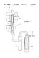
- FIG. 1is a schematic cross-sectional view of a reactor system
- FIG. 2is an enlarged cross-sectional view of the reactor chamber and converging-diverging nozzle
- FIG. 3is a plot of temperatures, pressures, specific volumes and nozzle throat areas as a function of gas velocity in the reactor apparatus
- FIG. 4is a graph plotting equilibrium concentrations in a titanium tetrachloride and hydrogen system as a function of temperature
- FIG. 5is a graph plotting equilibrium concentrations in a titanium tetrachloride and hydrogen system with added argon gas as a function of temperature
- FIG. 6is a graph plotting equilibrium concentrations in a methane decomposition system with solid carbon precipitation.
- FIG. 7is a graph plotting equilibrium concentrations in a methane decomposition system with solid carbon precipitation prevented.
- FIG. 8are side and top cross sectional views of a reaction chamber having a nozzle having two or more supply inlets.
- the fast quench reactor and method of operation described in this disclosuretake advantage of the high temperatures (5,000 to 20,000° C.) available in a high temperature heating means such as a thermal plasma to produce materials that are thermodynamically stable at these high temperatures. These materials include metals, alloys, intermetallics, composites, gases and ceramics.
- a converging-diverging (De Laval) nozzle located downstream from the plasma and reactant addition inlet(s)produces a rapid drop in kinetic temperature in a flowing gas stream. This effectively "freezes” or stops all chemical reactions. It permits efficient collection of desired end products as the gases are rapidly cooled without achieving an equilibrium condition. Resulting end products which have been produced in the plasma at high temperature but are thermodynamically unstable or unavailable at lower temperatures can then be collected due to resulting phase changes (gas to solid) or stabilization by cooling to a lower equilibrium state (gas to gas).
- the fast quench reactor and method of this inventionshall be described and illustrated forthwith in terms of a rapid heating means comprising a plasma torch and a stream of plasma arc gas.
- the rapid heating meanscan also include other rapid heating means such as lasers, and flames produced by oxidation of a suitable fuel, e.g. an oxygen/hydrogen flame.
- FIG. 1A schematic diagram of an ultra fast quenching apparatus is shown in FIG. 1.
- An enclosed axial reactor chamber 20includes an inlet at one end (shown to the left) and an outlet at its remaining end (shown to the right).
- a plasma torch 21is positioned adjacent to the reactor chamber. Torch 21 is used to thermally decompose an incoming gaseous stream within a resulting plasma 29 as the gaseous stream is delivered through the inlet of the reactor chamber 20.
- a plasmais a high temperature luminous gas which is at least partially (1 to 100%) ionized.
- a plasmais made up of gas atoms, gas ions, and electrons. In the bulk phase a plasma is electrically neutral.
- a thermal plasmacan be created by passing a gas through an electric arc. The electric arc will rapidly heat the gas by resistive and radiative heating to very high temperatures within microseconds of passing through the arc.
- the plasmais typically luminous at temperatures above 9000 K.
- a plasmacan be produced with any gas in this manner. This gives excellent control over chemical reactions in the plasma as the gas might be neutral (argon, helium, neon), reductive (hydrogen, methane, ammonia, carbon monoxide) or oxidative (oxygen, nitrogen, carbon dioxide). Oxygen or oxygen/argon gas mixtures are used to produce metal oxide ceramics and composites. Other nitride, boride, and carbide ceramic materials require gases such as nitrogen ammonia, hydrogen, methane, or carbon monoxide to achieve the correct chemical environment for synthesis of these materials.
- An incoming stream of plasma gasis denoted by arrow 31.
- the plasma gascan also be a reactant or can be inert.
- a gaseous stream of one or more reactants(arrow 30) is normally injected separately into the plasma 29, which is directed toward the downstream outlet of the reactor chamber 20.
- the gaseous stream moving axially through the reactor chamber 20includes the reactants injected into the plasma arc or within a carrier gas.
- Reactant materialsare usually injected downstream of the location where the arc attaches to the annular anode of the plasma generator or torch.
- Materials which can be injected into the arc regioninclude natural gas, such as is used in the Huels process for the production of ethylene and acetylene from natural gas.
- Gases and liquidsare the preferred forms of injected reactants. Solids may be injected, but usually vaporize too slowly for chemical reactions to occur in the rapidly flowing plasma gas before the gas cools. If solids are used as reactants, they will usually be heated to a gaseous or liquid state before injection into the plasma.
- a convergent-divergent nozzle 22is coaxially positioned within the outlet of the reactor chamber 20.
- the converging or upstream section of the nozzlerestricts gas passage and controls the residence time of the hot gaseous stream within the reactor chamber 20, allowing its contents to reach thermodynamic equilibrium.
- the contraction that occurs in the cross sectional size of the gaseous stream as it passes through the converging portions of nozzle 22change the motion of the gas molecules from random directions, including rotational and vibrational motions, to straight line motion parallel to the reactor chamber axis.
- the dimensions of the reactor chamber 20 and the incoming gaseous flow ratesare selected to achieve sonic velocity within the restricted nozzle throat.
- the confined stream of gasenters the diverging or downstream portions of the nozzle 22, it is subjected to an ultra fast decrease in pressure as a result of a gradual increase in volume along the conical walls of the nozzle exit.
- the resulting pressure changeinstantaneously lowers the temperature of the gaseous stream to a new equilibrium condition.
- An additional reactantsuch as hydrogen at ambient temperatures, can be tangentially injected into the diverging section of nozzle 22 (arrow 32) to complete the reactions or prevent back reactions as the gases are cooled.
- Supply inlets for the additional reactant gasare shown in FIG. 1 at 23.
- Numerals 24 and 25designate a coolant inlet and outlet for the double-walled structure of the reactor chamber 20. Coolant flow is indicated by arrows 33 and 34.
- the walls of nozzle 22 and a coaxial cool down chamber 26 downstream from itshould also be physically cooled to minimize reactions along their inner wall surfaces.
- Reaction particlesare collectable within a cyclone separator shown generally at 27.
- a downstream liquid trap 28such as a liquid nitrogen trap, can be used to condense and collect reactor products such as hydrogen chloride and ultra-fine powders within the gaseous stream prior to the gaseous stream entering a vacuum pump 29.
- FIG. 2further illustrates details of the converging-diverging nozzle structure.
- the same reference numeralsare used in FIG. 2 as in FIG. 1.
- the reactor chamber 20can be operated at atmospheric pressure or in a pressurized condition, while the chamber 26 downstream from nozzle 22 is maintained at a vacuum pressure by operation of pump 29.
- the sudden pressure change that occurs as the gaseous stream traverses nozzle 22brings the gaseous stream to a lower equilibrium condition instantly and prevents unwanted back reactions that would occur under more drawn out cooling conditions.
- Typical residence times for materials within the free flowing plasmaare on the order of milliseconds.
- the reactantsliquid or gas
- the injected stream of reactantsis injected normal (90° angle) to the flow of the plasma gases. In some cases positive or negative deviations from this 90° angle by as much as 30° may be optimum.
- the high temperature of the plasmarapidly vaporizes the injected liquid materials and breaks apart gaseous molecular species to their atomic constituents.
- metalstitanium, vanadium, antimony, silicon, aluminum, uranium, tungsten
- metal alloystitanium/vanadium, titanium/aluminum, titanium/aluminum/vanadium
- intermetallicsnickel aluminide, titanium aluminide
- ceramicsmetal oxides, nitrides, borides, and carbides
- metal halideschlorides, bromides, iodides, and fluorides
- Solid metal halide materialsare preferably vaporized and injected into the plasma as a liquid or gas to improve
- the reaction chamber 20is the location in which the preferred chemical reactions occur. It begins downstream from the plasma arc inlet and terminates at the nozzle throat. It includes the reactor areas in which reactant injection/mixing and product formation occurs, as well as the converging section of the quench nozzle.
- Temperature requirements within the reactor chamber and its dimensional geometryare specific to the temperature required to achieve an equilibrium state with an enriched quantity of each desired end product.
- the reaction chamberis an area of intense heat and chemical activity it is necessary to construct the reactor chamber of materials that are compatible with the temperature and chemical activity to minimize chemical corrosion from the reactants, and to minimize melting degradation and ablation from the resulting intense plasma radiation.
- the reactor chamberis usually constructed of water cooled stainless steel, nickel, titanium, or other suitable materials.
- the reactor chambercan also be constructed of ceramic materials to withstand the vigorous chemical and thermal environment.
- the reaction chamber wallsare internally heated by a combination of radiation, convection and conduction. Cooling of the reaction chamber walls prevents unwanted melting and/or corrosion at their surfaces.
- the system used to control such coolingshould maintain the walls at as high a temperature as can be permitted by the selected wall material, which must be inert to the reactants within the reactor chamber at the expected wall temperatures. This is true also with regard to the nozzle walls, which are subjected to heat only by convection and conduction.
- the dimensions of the reactor chamberare chosen to minimize recirculation of the plasma and reactant gases and to maintain sufficient heat (enthalpy) going into the nozzle throat to prevent degradation (undesirable back or side reaction chemistry).
- the length of the reactor chambermust be determined experimentally by first using an elongated tube within which the user can locate the target reaction threshold temperature.
- the reactor chambercan then be designed long enough so that reactants have sufficient residence time at the high reaction temperature to reach an equilibrium state and complete the formation of the desired end products.
- Such reaction temperaturescan range from a minimum of about 1700° C. to about 4000° C.
- the inside diameter of the reactor chamber 20is determined by the fluid properties of the plasma and moving gaseous stream It must be sufficiently great to permit necessary gaseous flow, but not so large that undesirable recirculating eddys or stagnant zones are formed along the walls of the chamber. Such detrimental flow patterns will cool the gases prematurely and precipitate unwanted products, such as subchlorides or carbon.
- the inside diameter of the reactor chamber 20should be in the range of 100 to 150% of the plasma diameter at the inlet end of the reactor chamber.
- the purpose of the converging section of the nozzleis to compress the hot gases rapidly into a restrictive nozzle throat with a minimum of heat loss to the walls while maintaining laminar flow and a minimum of turbulence. This requires a high aspect ratio change in diameter that maintains smooth transitions to a first steep angle (>45°) and then to lesser angles ( ⁇ 45°) leading into the nozzle throat.
- the purpose of the nozzle throatis to compress the gases and achieve sonic velocities in the flowing hot gaseous stream. This converts the random energy content of the hot gases to translational energy (velocity) in the axial direction of gas flow. This effectively lowers the kinetic temperature of the gases and almost instantaneously limits further chemical reactions.
- the velocities achieved in the nozzle throat and in the downstream diverging section of the nozzleare controlled by the pressure differential between the reactor chamber and the section downstream of the diverging section of the nozzle. Negative pressure can be applied downstream or positive pressure applied upstream for this purpose.
- the purpose of the diverging section of the nozzleis to smoothly accelerate and expand gases exiting the nozzle from sonic to supersonic velocities, which further lowers the kinetic temperature of the gases.
- smooth accelerationin practice requires use of a small diverging angle of less than 35 degrees to expand the gases without suffering deleterious effects of separation from the converging wall and inducing turbulence. Separation of the expanding gases from the diverging wall causes recirculation of some portion of the gases between the wall and the gas jet exiting the nozzle throat. This recirculation in turn results in local reheating of the expanding gases and undesirable degradation reactions, producing lower yields of desired end products.
- the super fast quench phenomena observed in this reactoris achieved by rapidly converting thermal energy in the gases to kinetic energy via a modified adiabatic and isentropic expansion through a converging-diverging nozzle.
- the gas temperature and pressure dropextremely fast and the gas reaches supersonic velocity. It is important to first raise the temperature of the reactants in the reactor chamber to a level at which the desired end product is more stable than other reaction products in equilibrium with it. This is normally a consequence of the fact that the free energy of the desired end product will decrease at the selected elevated temperatures in comparison to the remaining reaction products.
- this window of opportunityis very short-lived ( ⁇ 10 -3 sec) in a high temperature reactor.
- the reactor nozzle 22(FIG. 2) can be divided into three sections; the convergent reaction chamber 10, the nozzle throat 11, and the divergent quench chamber 12.
- the entrance angle to the throat area, the cross-sectional area of the throat, and the diverging angle after the throatall exert influence on the temperature, pressure, and velocity profiles of the plasma gas.
- the gasIn the converging-diverging nozzle, the gas is flowing from a higher pressure P 0 to a lower pressure P 1 . During passage of the gas through the nozzle, there will be a rapid transformation of thermal energy to kinetic energy. This kinetic energy will give rise to a high gas velocity after discharging from the nozzle. The gas enters the converging section at a low velocity and will emerge at the diverging section with a higher velocity.
- ⁇is the ratio of C p /C v where C p and C v are the heat capacities at constant pressure and volume, respectively.
- ⁇is 1.66 for Ar, 1.30 for H 2 , and 1.11 for C 2 H 2 .
- This equationcan be used to estimate the temperature drop across the nozzle throat if the initial and final pressures of the gases are known or vice versa.
- the mass flow rate, mis related to the cross-sectional area (A*) of the nozzle throat, the velocity (V) and the specific volume ( ⁇ ) of the gas at the throat.
- the specific volume ( ⁇ )is the inverse of gas density at the cross section. ##EQU2##
- A*is the cross-sectional area at the throat of the nozzle, and A is the cross-sectional area of the converging-diverging section.
- the preferred method for producing titanium from titanium tetrachlorideinvolves directing titanium tetrachloride vapor and a hydrogen into a hot plasma torch operated at 12 kW with a mixture of argon and hydrogen as the plasma gas (95% Argon: 5% Hydrogen, by volume) to decompose it to titanium and chlorine, followed by rapid expansion of the resulting hot gases and cooling with additional hydrogen to retain the titanium in an elemental solid metal state.
- the diameter and length (6.0 mm ⁇ 700.0 mm) of the reaction chamberwas chosen to obtain maximum mixing while maintaining a minimum of 4000 K temperature at the entrance of the nozzle throat.
- the reaction chamber, converging/diverging nozzlewere constructed from nickel 200 alloy to reduce corrosion. Standard equations were used to calculate the dimensions of the bell-shaped converging nozzle, nozzle throat diameter diverging angle, and diverging nozzle exit diameter.
- Plasma Torch10 kW laboratory plasma torch
- AnodeWater-Cooled Copper Cylinder 6.0 mm diameter ⁇ 20.0 mm in length
- Plasma Gas95% Argon, 5% Hydrogen, Average total gas flow was maintained at 23.6 liters/min.
- Reactant InjectionGaseous (200° C.) Titanium tetrachloride at the point where the plasma plume exits the plasma torch.
- the hot titanium tetrachloride injection tubes, reaction chamber and converging/diverging nozzle sectionwere constructed from nickel 200 alloy to minimize corrosion.
- Injection RateVaporized Titanium tetrachloride was injected at the rate of 10.0 to 15.0 milliliters/hour. This resulted in a titanium metal powder production rate of 5 grams per hour.
- Reaction ChamberWater-cooled Nickel 200 cylinder 6.0 mm ⁇ 20.0 mm
- Nozzle throat2.0 mm ⁇ 1.0 mm in length, determined from standard equations,
- Diverging NozzleConical shaped with 14° included angle expanding out to a 12.0 mm diameter.
- Cool down sectionWater-cooled stainless steel, 12.0 mm diameter ⁇ 600.0 mm
- Cyclone collectorsWater-cooled stainless steel, 12.0 mm inlet and outlet diameter, 50.0 mm inside diameter body, designed to maintain high entrance and exit velocity
- Off-Gas CleanupAfter product collection the process gas was passed through a liquid nitrogen cold trap and HEPA filter to remove HCl gas and residual titanium particles before the gas enter the mechanical vacuum pump.
- Vacuum SystemA mechanical vacuum pump was used to maintain pressure downstream from the nozzle throat at 5.0 to 10.0 Torr (mm Hg)
- FIGS. 1 and 2 of the drawingspertain to an apparatus tested for recovering elemental metals from metal-containing compounds.
- the elemental metalis titanium and the metal-containing compound is titanium tetrachloride (TiCl 4 ).
- TiCl 4titanium tetrachloride
- the illustrated apparatusis suitable for use with other metals and compounds where plasma processing of the compound requires ultra fast quenching to prevent back reactions.
- the plasma torch 21 located at the reactor chamber inletthermally decomposes an incoming gaseous stream comprised of a metal-containing compound plus one or more reactants as the resulting gaseous stream moves axially through the reactor chamber 20 in conjunction with a carrier gas.
- the resulting hot gaseous streamis then directed through the coaxial convergent-divergent nozzle 22.
- the convergent portion 10 of the nozzle 22controls the residence time of the hot gaseous stream within the reactor chamber 20, thereby allowing its contents to reach thermodynamic equilibrium. It also streamlines the flow of hot gases, converting their motion from random movement to straight line movement along the central nozzle axis.
- the divergent portion 12 of the nozzle 22subjects the stream to an ultra fast decrease in pressure.
- Quenching streams of gasare introduced into the hot gaseous stream through inlets 23 as it passes through the nozzle. This rapidly cools the contents of the hot gaseous stream at a rate that condenses the elemental metal and inhibits formation of equilibrium products.
- the plasma reductionis based on a quasi equilibrium-temperature quench sequence in which the initiation of nucleation is controlled by passage of a heated gaseous stream through a converging-diverging nozzle geometry. Results from present system tests have shown the feasibility of the process.
- the powder productis extremely fine (-20 nm).
- FIG. 4shows the species as a function of temperature for a TiCl 4 +2H 2 system at 1 atm.
- argontaken into account (to 96%) there is basically no change in the relative species distribution.
- FIG. 4shows the chlorides as stripped off, until at temperatures above 5000 K there is a substantial amount of only Ti, Ti + , Cl, Cl - , TiCl, HCl and H 2 .
- the amount of hydrogenrelative to that required for a stoichiometric HCl product, is increased to 32:1 this diagram shifts to lower temperatures (FIG. 5). In all cases the requirement is for good mixing and a sufficient residence time of the reactants in the plasma.
- homogeneous nucleation of particles from the vapor in a plasma systemhas been studied theoretically and published discussion of such issues are readily available.
- the initiation of homogeneous nucleationdepends on the formation of small atom clusters which arise due to collisions. Normally, the cluster evaporation rate is much greater than the condensation rate and the particle clusters do not grow. However at sufficiently low temperatures the vapor becomes supersaturated and the condensation rate drastically increases. This results in a nucleation burst after which time the particles increase in size slowly.
- the saturation vapor pressures of Ti--Cl compounds at all temperaturesare greater than that of Ti, and it is possible to selectively condense Ti metal.
- the presence of hydrogenserves to isolate the titanium from the chlorine atoms by forming both HCl and TiH in the gas phase.
- the converging-diverging nozzle configuration used in supersonic flow applicationsoffers possibilities to control both the temperature quench rate and the concentration at which the plasma becomes "frozen” during the expansion.
- the converging-diverging DeLaval nozzle and the associated Prandtl-Meyer expansion processare discussed in standard texts on compressible fluid flow. In such expansion nozzles the hot plasma gas undergoes an approximate isentropic expansion and the energy in the gas (its enthalpy) is converted to unidirectional velocity in the diverging nozzle. When the exit pressure is sufficiently low, it is possible to reach supersonic speeds. Non-adiabatic expansion processes which are attained in practice aid in the resultant temperature search.
- Nitrogen gas impurities in such systemsresult in the formation of solid NH 4 Cl powder which can be separated from the (black) powder produced by heat treating at about 400° C. in flowing hydrogen. Oxygen impurities, however, result in TiO 2 production. In virtually all runs to date, the only chlorine in the final product is that tied up as ammonium chloride and the product can be upgraded to be chlorine free. Presently HCl is condensed in a cold trap placed just before the downstream pumping system.
- the powder producedis black.
- the as-produced producthas been analyzed by SEM and characterized by Energy Dispersion Spectra (EDS).
- EDSEnergy Dispersion Spectra
- a SEM scan of the powdershowed finer structure.
- a typical x-ray diffraction (XRD) scanis featureless (flat). It shows no crystal structure nor any short range ordering.
- An electron diffraction patternconfirms this result.
- the maximum yield of titanium metal to date with the present systemis 5 gm/hr. It is 100% free of chlorine.
- TiO 2 production in the 50 nm rangecan also be carried out in the existing facilities.
- TiCl 4is injected into an argon plasma and mixed with O 2 just before the quench zone.
- Most of the TiO 2 produced todayis used in the paint industry and a 50 nm size (rather than the present 200 nm) is advantageous.
- Titanium dioxide particlescan be produced with average diameters of 10 nanometers or less in the narrow size ranges as defined, which can find use as a sun blocking agent for protecting human skin against harmful effects of sunlight.
- the processmeets all requirements for titanium production, in that it provides downstream reduction in a kinetically controlled reactor to remove halide from back reactions, leaving free metal in the exiting gaseous stream. Unwanted atomic reactions cannot occur in the reactor due to the short residence time of the gaseous stream.
- Methane conversion to acetylene in a high temperature reactorfollows the theoretical chemical reaction: 2CH 4 ⁇ C 2 H 2 +3H 2 .
- the main by-productis hydrogen, instead of tars and acetylene black.
- Such studiesalso showed that pyrolysis in the presence of hydrogen suppressed carbon formation.
- FIGS. 6 and 7respectively show the equilibrium compositions of methane conversion to acetylene with (FIG. 6) and without (FIG. 7) solid carbon nucleation in the reaction. It is clearly seen from these results that if C 2 H 2 is allowed to ⁇ slowly ⁇ reach equilibrium at low temperatures it will decompose to acetylene black. Therefore, to maximize acetylene formation, the nucleation of solid carbon from acetylene must be suppressed at all temperatures.
- the nucleation rate, I iof solid carbon from a supersaturated hydrocarbon vapor species i is given by: ##EQU6## where ⁇ is surface tension, P i is the vapor pressure of species i, and v is the molecular volume of species i.
- SSa ratio of P i /P.sub. ⁇ , is the supersaturation of species i with its solid at temperature T. In SS is the degree of supersaturation of the vapor pressure of species i at the specific temperature T.
- the homogeneous nucleation of carbon solid from the supersaturated hydrocarbon vapor species ioccurs by the following sequence of events:
- the nucleationoccurs like a burst over a relatively short time period (10 -6 s).
- the nucleationterminates due to the loss of nucleating species in the gas phase which are depleted by diffusion to the freshly formed particles.
- the super fast quench phenomena observed in this reactoris achieved by rapidly converting thermal energy in the gases to kinetic energy via a modified adiabatic and isentropic expansion through a converging-diverging nozzle.
- the gas temperature and pressure dropextremely fast and the gas reaches supersonic velocity.
- Acetyleneis more stable than other alkanes or alkenes at temperatures above 2000 K. This is a consequence of the fact that the free energy of acetylene decreases at elevated temperatures compared to other hydrocarbons.
- the average temperatureshould be between 2500 to 2000 K after CH 4 injection, followed by quenching the gas composition immediately to ⁇ 500 K to stabilize the acetylene.
- Locating the proper temperature zone for maximum C 2 H 2 formation before quenchingis important to minimize solid carbon nucleation.
- the plasma temperatureis very high (>>5000 K) and the plasma gas is very viscous. This temperature will need to be cooled to an average of 2500-2000 K by mixing with injected methane for maximum acetylene yield. To achieve good mixing between methane and plasma gas to reach a uniform average reaction temperature it is necessary to overcome the high viscosity of the plasma gas.
- the window of opportunity for stabilizing maximum acetylene yieldis very narrow and short. Therefore, defining the location of methane injection and position of the nozzle for immediate quenching of the product is extremely important.
- a Plasma Fast Quench Reactorwas designed and built, utilizing expansive cooling to convert methane to acetylene. It was constructed basically as shown in FIGS. 1 and 2.
- Hydrogenwas used as a reactive plasma gas to heat methane to reaction temperatures and also served as a suppressant for solid carbon nucleation from the reaction. Downstream in the nozzle region, hydrogen could be used as an optional coolant of the diverging section of the nozzle if it is desirable.
- Initial experiments of methane conversion based on carbon balancesyielded a product, in a single pass, consisting of 71% acetylene, 27% carbon black and 2% ethylene.
- the product gasalso contained hydrogen as a by-product.
- the processhas a very high selectivity to acetylene production.
- the converging-diverging nozzleconverted thermal energy to kinetic energy. Gas velocity downstream from the nozzle was believed to be supersonic; opportunities to use this kinetic energy to drive a turbine-generator are obvious.
- By-product hydrogencould be used as feed stock for other processes or could be burned to drive a turbine generator to provide additional electrical power to the process.
- the acetylenecan be converted to other high value commodity chemicals by applying established chemical processes down stream of the reactor.
- Table 3is a condensation of information relating to application of this system to already proven end products. It lists reactants and plasma gas combinations that have successfully produced the identified products.
- the plasma gaswas changed to a mixture of Ar, He, and H 2 in the volume ratio of 65:32.5:2.5 respectively. This also increased the arc voltage and minimized the radiative heat loss from the plasma to the cooled anode thus maximizing both the enthalpy (energy content) and temperature, while still providing sufficient hydrogen for reaction with the fluorine (F 2 +H 2 ⁇ 2HF) and the formation of uranium-metal in the condensation region of the nozzle and reactor.
- the final problem to be solvedwas optimization of the injector to insure "good" mixing of the UF 6 with the plasma gas.
- a UF 6 feed systemwhich would provide UF 6 at controlled temperature (between about 10 and about 100° C.) and elevated pressure (between 40 and about 75 psi) was designed.
- the UF 6 gaswas mixed with an argon carrier gas and transversely injected at velocities ranging from 100-600 m/s. Operation of the injector at these velocities and avoidance of injector plugging and erosion required a reduction of the injector orifice size to 1-2.5.
- the optimum injectionwas found to be around 200 m/s. This condition resulted in adequate mixing and a successful experiment.
- the first three equationsare three--body reactions which proceed at a relatively slow rate as compare with the gas velocity and nozzle transit time.
- the relative slow rate of these reactionsresult in elevated non-equilibrium populations of atomic hydrogen and fluorine in the expansion process.
- the presence of molecular hydrogenplays an important role in the process by rapidly reacting with free atomic fluorine atoms and thus preventing atomic fluorine from attacking elemental uranium and formation of undesirable UFx.
- Reactions 4 and 5are two body reactions, which proceed at a rate significantly higher than reactions 1-3. For a completely dissociated mixture the formations of HF is limited by the reaction rates for reactions 1 and 2.
- the reaction of room temperature uranium metal with molecular F 2 and HFis known to be a relatively slow process.
- the reaction rate for the reaction of uranium metal and atomic fluorine (F)is not currently known but has the potential to be a significant mechanism for formation of uranium fluorides due to the high reactivity atomic fluorine.
- injection of molecular hydrogen at the nozzle exitwould be advantageous to remove the atomic fluorine.
- injection of molecular hydrogen at the nozzle throatwill be even more advantageous.
- the injection pointcan be either slightly upstream, down stream, or in the nozzle throat.
- the addition of cold molecular hydrogen gashas the added benefit of increasing the quenching of the product mixture by increasing the gas velocity and by thermal cooling of the gas.
- ultrafine titanium dioxide ceramic powderobtained by oxidizing titanium tetrachloride in an oxygen enriched plasma gas. This system has been successfully used to produce an ultrafine particle size range of less than 500 nanometers, with 10-100 nanometers being the preferred range. The particles have been successfully produced within a narrow size range, meaning that 90 percent of the particles would fall within a 25 nanometer size range.
- the reaction chamber, converging/diverging nozzle and downstream cooling sectionwere constructed of copper coated with an alumina type ceramic.
- the purpose of the ceramicwas to prevent corrosion of the cooper by HCl produced in this process and reduce heat loss from the reaction zone.
- the reactor chamber for this original system testwas 2.0 cm in diameter by 10.0 cm in length.
- the quench sectionconsisted of a 90° included angle converging section followed by a 3.0 mm diameter throat and a 90° included angle diverging section issuing into a 4.0 cm diameter by 20 cm long cool down section.
- Four tangential hydrogen gas jets(1.0 mm diam) were placed in the diverging section of the nozzle approximately 5 mm downstream from the nozzle throat. Injection of cold hydrogen gas at this point seemed to improved yields of titanium. It was later learned that even better quenching could be accomplished by reducing the expansion angle of the diverging section of the nozzle to less than a 20° included angle, with the optimum diverging included angle being 6° to 14°.
- Titanium metal powder production in the early laboratory devicewas on the order of 0.1 to 0.5 grams per hour. This yield was improved to 0.5 to 1.0 gram per hour by (1) optimizing the geometry of the reactor; (2) addition of 1 to 5% hydrogen to the argon plasma gas to increase heat to the process while also preheating the hydrogen reductant for reaction with titanium tetrachloride; (3) injecting liquid or vaporized titanium tetrachloride into the reaction zone with a minimum of carrier gas; and (4) use of hydrogen as the carrier gas.
- reaction zone geometrywas optimized by conducting two dimensional modeling of the fluid dynamics of such a system. Modeling results determined that reaction zone diameter should be no larger than 200% of the plasma torch anode exit diameter with the optimum being 110% to 150%. This prevents recirculation of reaction gases in the reaction zone which would contribute to undesirable side reactions and decrease product yields.
- Gas temperatureswere measured experimentally along an elongated reaction section and were also modeled using a two dimensional fluid dynamics model to determine the optimum length of the reaction zone before the converging section.
- a reaction zone lengthwas chosen from this data for a given plasma input power level, plasma gas flow, and reactant input rate which would result in gas temperatures at the entrance to the nozzle throat to be greater than the required equilibrium temperature of the desired end product--4000 K (for production of titanium).
- a high aspect ratio converging sectionwas designed such that the radius of the convex and concave surfaces leading into the nozzle throat were approximately equal to the diameter of the nozzle throat. This converging geometry allows achieving the highest possible velocity at the entrance to the nozzle throat while limiting heat loss to the walls of the converging section or separation of the gas flow from the converging surface.
- the optimum area (diameter) of the nozzle throatwas calculated from equations available in texts pertaining to nozzle design.
- the nozzle throatwas designed so that with the temperature, gas composition, mass flow, and pressure of the gas entering the nozzle known (or estimated) sonic or near sonic gas velocities are achieved in the nozzle throat.
- the nozzle throatshould be as short as possible.
- R* and h*designating the radius of curvature and throat height respectively: ##EQU7## where T 0 and a 0 are the gas temperature and speed of sound respectively in the reaction zone.
- the divergence angle and area at the exit of the diverging nozzlewere determined from standard texts on fluid dynamics and aerospace rocket motor design. In addition, two dimensional models of fluid flow under expected experimental conditions were also used to optimize the divergence angle and exit area of the nozzle. It was concluded that the optimum divergence included angle was less than 35° and preferably in the range of 10° to 14° for optimum expansion and acceleration of the gas. The maximum exit area (diameter) of the diverging nozzle was again determined by calculation from equations available in standard texts on fluid flow and rocket engine design.
- the maximum allowable nozzle exit areadepends on the mass flow through the nozzle and pressure difference between the reaction zone and the downstream cooling section. Choice of too large an expansion angle or too large an exit area will result in the gas flow "peeling off” or separating from the wall, which results in the undesirable conditions of turbulence, gas recirculation, gas reheating, and side or back reaction degradation of the desired end products.
- the purpose of the cool down section of the plasma fast quench reactor deviceis to reduce the gas velocity while removing heat energy (which results from the decrease in velocity) in the gas at a rate sufficient to prevent the gas from increasing in kinetic temperature. Passage of the gaseous stream through the restrictive nozzle opening reduces its kinetic temperature, but remove no energy from the gas. The exiting gaseous stream is slowly warmed as some random motion of the gaseous contents is restored. This heat must be immediately removed from the system as it is produce, thereby maintaining the kinetic temperature of the resulting gaseous stream at a desired equilibrium level and preventing back reactions downstream from the nozzle.
- Plasma quench processes for production of ultrafine materialsrequire product collection capability downstream of the quench nozzle, preferably downstream of the cool down section.
- Bench scale experiments to datehave used cyclonic collectors of standard dimensions described in the literature for gas and mass flows several time smaller than called for in the literature. This accommodates sonic or near sonic gas velocities through the cyclones, which allows efficient removal of ultrafine material (10 to 50 nm diameter powders).
- the third process parameter that determines the temperature drop across the nozzleis the ratio of the up stream pressure (P 0 , in reaction zone) to the downstream pressure (P 1 , cool down zone).
- P 0up stream pressure
- P 1downstream pressure
- the ratio P 0 /P 1 of 0.01 to 0.26was maintained.
- the experimental systemswere operated with the reaction zone pressure of approximately 700 to 800 Torr (ca. 1 atm.) and downstream pressure maintained between 10 and 200 Torr (0.26 to 0.01 atm.).
- the low downstream pressurewas accomplished using a mechanical vacuum pump.
- the quench systemwould be designed to operate with elevated pressures in the plasma torch and reaction chamber of 5 to 10 atmospheres pressure. This would accomplish the desired pressure drop across the nozzle while reducing or possibly eliminating the need for a vacuum device to lower the pressure on the downstream side of the nozzle.
- a bench scale reactorwas constructed for synthesis of titanium, vanadium, aluminum, and Ti/V Alloys. This equipment was designed for operation at 12 KW input power to the plasma torch, using a plasma gas flow of 50 scfh and a plasma gas made up of 95% argon and 5% hydrogen gas. The equipment used to produce these materials consisted of a small bench scale plasma torch operated at 12 kW electrical input power attached to a reactor section, quench nozzle, cyclone powder collector, liquid nitrogen cold trap to collect by-product HCl, and mechanical vacuum pump.
- titanium tetrachloridewas heated above its boiling point and injected into the reaction chamber at the junction between the plasma torch and the reaction section.
- the reaction section, quench nozzle, and expansion chamberwere constructed of water cooled nickel.
- the reaction sectionwas 11.0 mm inside diameter and 150.0 mm in length.
- the quench nozzle sectionconsisted of a high aspect ratio converging section followed by a 6.2 mm nozzle, and 12° included angle expansion section followed a 20.0 mm I.D., 50.0 cm cool down section.
- the cooled mixture of titanium powder and gaswas passed through two sonic cyclone particle separators to collect the ultrafine powder. Hydrogen chloride vapor was condensed out in a liquid nitrogen cooled cold trap to prevent damage to the mechanical vacuum pump down stream from the particle collection. Titanium was produced according to equation (1) below:
- Ultrafine vanadium metal powderwas produced using the bench scale apparatus described above. Vanadium tetrachloride liquid (B.P. 145° C.) was heated to vapor and injected in the same manner as titanium tetrachloride described above with hydrogen carrier gas. Ultrafine vanadium metal powder was produced at the rate of a 0.5 gram per hour according to one of the following equations:
- An ultrafine powder consisting of an alloy of titanium and vanadiumwas produced by two methods.
- Method 1used a mixture of solid vanadium trichloride dissolved in liquid titanium tetrachloride. This mixture was then heated to vapor and injected into the plasma quench reactor in the same manner as with titanium above.
- Method 2vaporized liquid vanadium tetrachloride and vaporized liquid titanium tetrachloride were injected into the plasma quench reactor using separate injectors located in the same axial position but 180° apart on the circumference of the reactor.
- the chemical equations usedare:
- Ultrafine aluminum metal powderwas produced by vaporizing (subliming) solid aluminum trichloride in a specially designed oven and carried into the plasma quench reactor in a stream of hydrogen gas in the manner described for titanium above. Special care was needed to insure all sections of the injection system were maintained above 200° C. to prevent formation of solid aluminum trichloride.
- the processutilized the following equation:
- FIG. 8shows a reaction chamber 20 having a virtual convergent-divergent nozzle.
- the chamber 20has a plasma gas 31, plasma arc 21, and resulting plasma similar to FIG. 1.
- Supply inlets 23focus the incoming reactant streams 32 so as force the reactants toward the center of the reaction chamber 20.
- the plasma gas 31 and reactant streams 32 as they come togetherproduce an expansion of the reactant stream toward the outlet end of reaction chamber 23 to produce flow lines 34 with flow impedence 35. This expansion results in rapid cooling of the reactants.
- Supply inlets 25allow reactant streams 33 containing for example a reducing gas, such as hydrogen, to prevent back reactions and enhance the virtual nozzle effect and the production of the desired product.
Landscapes
- Chemical & Material Sciences (AREA)
- Engineering & Computer Science (AREA)
- Organic Chemistry (AREA)
- Mechanical Engineering (AREA)
- Physics & Mathematics (AREA)
- Materials Engineering (AREA)
- Life Sciences & Earth Sciences (AREA)
- Environmental & Geological Engineering (AREA)
- Metallurgy (AREA)
- Manufacturing & Machinery (AREA)
- Geology (AREA)
- General Life Sciences & Earth Sciences (AREA)
- Chemical Kinetics & Catalysis (AREA)
- Plasma & Fusion (AREA)
- General Health & Medical Sciences (AREA)
- Inorganic Chemistry (AREA)
- Health & Medical Sciences (AREA)
- Geochemistry & Mineralogy (AREA)
- Toxicology (AREA)
- Nanotechnology (AREA)
- Spectroscopy & Molecular Physics (AREA)
- Composite Materials (AREA)
- General Physics & Mathematics (AREA)
- Condensed Matter Physics & Semiconductors (AREA)
- Crystallography & Structural Chemistry (AREA)
- Electromagnetism (AREA)
- Combustion & Propulsion (AREA)
- Physical Or Chemical Processes And Apparatus (AREA)
- Manufacture And Refinement Of Metals (AREA)
- Inorganic Compounds Of Heavy Metals (AREA)
- Organic Low-Molecular-Weight Compounds And Preparation Thereof (AREA)
- Manufacture Of Metal Powder And Suspensions Thereof (AREA)
- Catalysts (AREA)
Abstract
Description
TABLE 2______________________________________Reaction Temperature K Log K.sub.p (or ln SS)______________________________________C(g) = C(s) 3200 -0.18 3000 0.17 2800 0.591/2C.sub.2 (g) = C(s) 3400 -1.77 3200 -1.61 3000 0.411/3C.sub.3 (g) = C(s) 3200 -1.58 3000 1.39 2800 2.551/2C.sub.2 H(g) = C(s) + 1/4H.sub.2 3000 0.86 2500 1.17 2000 2.81/2C.sub.2 H.sub.2 (g) = C(s) + 1/H.sub.2 2000 -5.48 1500 -8.28______________________________________
H+H+M=H2(g)+M (1)
H+F+M=HF(g)+M (2)
F+F+M=F2(g)+M (3)
H2F+HF(g)+H (4)
H+F2=HF(g)+F (5)
TABLE 3__________________________________________________________________________ Injection Injection C-D NozzleReactants Plasma Gas Method Position Shape (angle) Products__________________________________________________________________________TiCl.sub.4 + H.sub.2 Argon/ TiCl.sub.4 + H.sub.2 3.0-6.0 mm C-45° to bell Titanium Hydrogen @ 180- from Torch shaped Metal + 200° C. exit D-25-6° HCL gasVCl.sub.4 + H.sub.2 Argon/ VCl.sub.4 + H.sub.2 same as same as Vanadium Hydrogen @ 180- above above Metal + 200° C. HCl gasAlCl.sub.3 + H.sub.2 Argon/ AlCl.sub.3 + H.sub.2 same as same as Aluminum Hydrogen @ 120- above above Metal + 150° C. HCL gasTiCl.sub.4 + Argon/ TiCl.sub.4 /VCL.sub.3 or 4 + same as same as TiV AlloyVCl.sub.3 (or Hydrogen H.sub.2 above above powder +VCl.sub.4) + H.sub.2 180-200° C. HCl gasTiCl.sub.4 + Argon/ TiCl.sub.4 (liq) same as same as TiB.sub.2BCl.sub.3 + Hydrogen @ 50 psi + above above compositeH.sub.2 BCl.sub.3 (gas) @ Ultrafine 50 psi + powder H.sub.2 ceramicTiCl.sub.4 + O.sub.2 Argon/ TiCl.sub.4 (liq) TiCl.sub.4 (liq) C-Bell Shaped Ultrafine Oxygen or @ 50 psi + 1-3 mm from D-10 to 25° TiO.sub.2 ceramic Oxygen O.sub.2 torch) @ included powder 50 psi exitWF.sub.6 + H.sub.2 Argon/Hydrog WF.sub.6 (g) @ WF.sub.6 (g) at C-Conical Ultrafine en/or 50 psi, 80- torch exit D-Conical 10- Tungsten Hydrogen 120° C. 20° included Metal powderUF.sub.6 + H.sub.2 Argon/Hydrog UF.sub.6 (g) @ UF.sub.6 (g) at C-Conical UltrafineArgon en/Helium 40--75 psi, torch exit D-Conical 10- Uranium 20-100° C. 20° included metal powderH.sub.2 + CH.sub.4 Argon/ CH.sub.4 (gas) @ interior of C-Bell Shaped 80% + Hydrogen or 50-100 psi torch or 1-3 D-10 to 25° Acetylene Hydrogen mm from included Lesser torch exit amounts of ethylene & carbon (s)Argon + Argon CH.sub.4 (gas) @ Interior of C-Bell shaped UltrafineCH.sub.4 56-100 psi torch or D-10 to carbon black 1-3 mm from 25° included powder torch exit__________________________________________________________________________
TiCl.sub.4 (g)+2H.sub.2 (g)+T>3000° C.→Ti(s)+2HCl(g)
2VCl.sub.3 (g)+3H.sub.2 (g)+T>3000° C.→2V(s)+6HCl(g)
VCl.sub.4 (g)+2H.sub.2 (g)+T>3000° C.→V(s)+2HCl(g)
10TiCl.sub.4 (g)+2VCl.sub.3 (g)+23H.sub.2 (g)+T>3000° C.→10Ti(s)+2V(s)+46HCl(g)
5TiCl.sub.4 (g)+VCl.sub.4 (g)+12H.sub.2 (g)+T>3000° C.→5Ti(s)+V(s)+24HCl(g)
AlCl.sub.3 (g)+3H.sub.2 (g)+T>3000° C.→2Al(s)+6HCl(g)
Claims (23)
Priority Applications (5)
| Application Number | Priority Date | Filing Date | Title |
|---|---|---|---|
| US09/076,922US5935293A (en) | 1995-03-14 | 1998-05-12 | Fast quench reactor method |
| US09/320,784US6187226B1 (en) | 1995-03-14 | 1999-05-27 | Thermal device and method for production of carbon monoxide and hydrogen by thermal dissociation of hydrocarbon gases |
| US09/781,931US6821500B2 (en) | 1995-03-14 | 2001-02-12 | Thermal synthesis apparatus and process |
| CA002408994ACA2408994C (en) | 1995-03-14 | 2002-10-21 | Thermal synthesis apparatus and method |
| US10/843,965US7576296B2 (en) | 1995-03-14 | 2004-05-11 | Thermal synthesis apparatus |
Applications Claiming Priority (2)
| Application Number | Priority Date | Filing Date | Title |
|---|---|---|---|
| US08/404,395US5749937A (en) | 1995-03-14 | 1995-03-14 | Fast quench reactor and method |
| US09/076,922US5935293A (en) | 1995-03-14 | 1998-05-12 | Fast quench reactor method |
Related Parent Applications (1)
| Application Number | Title | Priority Date | Filing Date |
|---|---|---|---|
| US08/404,395Continuation-In-PartUS5749937A (en) | 1995-03-14 | 1995-03-14 | Fast quench reactor and method |
Related Child Applications (2)
| Application Number | Title | Priority Date | Filing Date |
|---|---|---|---|
| US09/320,784Continuation-In-PartUS6187226B1 (en) | 1995-03-14 | 1999-05-27 | Thermal device and method for production of carbon monoxide and hydrogen by thermal dissociation of hydrocarbon gases |
| US09/781,931Continuation-In-PartUS6821500B2 (en) | 1995-03-14 | 2001-02-12 | Thermal synthesis apparatus and process |
Publications (1)
| Publication Number | Publication Date |
|---|---|
| US5935293Atrue US5935293A (en) | 1999-08-10 |
Family
ID=23599427
Family Applications (3)
| Application Number | Title | Priority Date | Filing Date |
|---|---|---|---|
| US08/404,395CeasedUS5749937A (en) | 1995-03-14 | 1995-03-14 | Fast quench reactor and method |
| US09/076,922Expired - LifetimeUS5935293A (en) | 1995-03-14 | 1998-05-12 | Fast quench reactor method |
| US09/569,146Expired - LifetimeUSRE37853E1 (en) | 1995-03-14 | 2000-05-11 | Fast quench reactor and method |
Family Applications Before (1)
| Application Number | Title | Priority Date | Filing Date |
|---|---|---|---|
| US08/404,395CeasedUS5749937A (en) | 1995-03-14 | 1995-03-14 | Fast quench reactor and method |
Family Applications After (1)
| Application Number | Title | Priority Date | Filing Date |
|---|---|---|---|
| US09/569,146Expired - LifetimeUSRE37853E1 (en) | 1995-03-14 | 2000-05-11 | Fast quench reactor and method |
Country Status (9)
| Country | Link |
|---|---|
| US (3) | US5749937A (en) |
| EP (1) | EP0815271A4 (en) |
| JP (1) | JP4139435B2 (en) |
| CN (1) | CN1052759C (en) |
| AU (1) | AU694024B2 (en) |
| BR (1) | BR9607210A (en) |
| CA (1) | CA2215324C (en) |
| NO (1) | NO318231B1 (en) |
| WO (1) | WO1996028577A1 (en) |
Cited By (171)
| Publication number | Priority date | Publication date | Assignee | Title |
|---|---|---|---|---|
| WO2001046067A1 (en)* | 1999-12-21 | 2001-06-28 | Bechtel Bwxt Idaho, Llc | Hydrogen and elemental carbon production from natural gas and other hydrocarbons |
| USRE37853E1 (en)* | 1995-03-14 | 2002-09-24 | Betchel Bwxt Idaho, Llc | Fast quench reactor and method |
| US20030143153A1 (en)* | 2001-04-24 | 2003-07-31 | Tekna Plasma Systems, Inc. | Plasma synthesis of metal oxide nanopowder and apparatus therefor |
| US6606855B1 (en) | 1999-06-08 | 2003-08-19 | Bechtel Bwxt Idaho, Llc | Plasma reforming and partial oxidation of hydrocarbon fuel vapor to produce synthesis gas and/or hydrogen gas |
| US20040050208A1 (en)* | 2002-09-12 | 2004-03-18 | Millennium Inorganic Chemicals, Inc. | Method of making elemental materials and alloys |
| EP1413354A1 (en)* | 2002-10-21 | 2004-04-28 | Bechtel BWXT Idaho, LLC | Thermal synthesis apparatus and method |
| US20040208805A1 (en)* | 1995-03-14 | 2004-10-21 | Fincke James R. | Thermal synthesis apparatus |
| US6821500B2 (en) | 1995-03-14 | 2004-11-23 | Bechtel Bwxt Idaho, Llc | Thermal synthesis apparatus and process |
| US20050065391A1 (en)* | 2003-09-23 | 2005-03-24 | Synfuels International, Inc. | Process for the conversion of natural gas to hydrocarbon liquids |
| US20050065392A1 (en)* | 2003-09-23 | 2005-03-24 | Synfuels International, Inc. | Process for the conversion of natural gas to reactive gaseous products comprising ethylene |
| WO2005035807A1 (en)* | 2003-09-19 | 2005-04-21 | Sri International | Methods and apparatuses for producing metallic compositions via reduction of metal halides |
| US20050115933A1 (en)* | 2003-12-02 | 2005-06-02 | Kong Peter C. | Plasma generators, reactor systems and related methods |
| US20050119398A1 (en)* | 2003-09-11 | 2005-06-02 | Lu Zhang | Plasma synthesis of metal oxide nanoparticles |
| US20050118094A1 (en)* | 2003-09-11 | 2005-06-02 | Lu Zhang | Plasma synthesis of metal oxide nanoparticles |
| AU2002301589B2 (en)* | 2002-10-22 | 2005-08-25 | Bechtel Bwxt Idaho, Llc | Thermal synthesis apparatus and method |
| US20050258149A1 (en)* | 2004-05-24 | 2005-11-24 | Yuri Glukhoy | Method and apparatus for manufacture of nanoparticles |
| US20050288516A1 (en)* | 2004-06-28 | 2005-12-29 | Warren Jack S | Use of a device or devices, such as a convergent divergent funnel mixer, to optimize the available reaction volume, the raw material feed ratios and the weight hourly space velocity in a tube reactor |
| WO2006021945A1 (en)* | 2004-08-26 | 2006-03-02 | E.S.T. Ecological Systems Ltd. | Method and system for treating chemical waste |
| WO2005116650A3 (en)* | 2004-04-19 | 2006-04-13 | Sdc Materials Llc | High throughput discovery of materials through vapor phase synthesis |
| WO2005099320A3 (en)* | 2004-04-09 | 2006-04-27 | Plasmatreat Gmbh | Method and device for producing low-pressure plasma and the use thereof |
| US20060103318A1 (en)* | 2004-11-17 | 2006-05-18 | Bechtel Bwxt Idaho, Llc | Chemical reactor and method for chemically converting a first material into a second material |
| US20060159596A1 (en)* | 2002-12-17 | 2006-07-20 | De La Veaux Stephan C | Method of producing nanoparticles using a evaporation-condensation process with a reaction chamber plasma reactor system |
| US20060191372A1 (en)* | 2003-07-04 | 2006-08-31 | Jawad Haidar | Method and apparatus for the production of metal compounds |
| US20060230149A1 (en)* | 2005-04-07 | 2006-10-12 | Cluster Resources, Inc. | On-Demand Access to Compute Resources |
| US20070021637A1 (en)* | 2005-02-18 | 2007-01-25 | Synfuels International, Inc. | Absorption and conversion of acetylenic compounds |
| US20070045116A1 (en)* | 2005-08-26 | 2007-03-01 | Cheng-Hung Hung | Electrodepositable coating compositions and related methods |
| US20070048550A1 (en)* | 2005-08-26 | 2007-03-01 | Millero Edward R | Coating compositions exhibiting corrosion resistance properties, related coated substrates, and methods |
| US20070048540A1 (en)* | 2005-08-26 | 2007-03-01 | Ragunathan Kaliappa G | Coating compositions exhibiting corrosion resistance properties, related coated substrates, and methods |
| US20070048206A1 (en)* | 2005-08-26 | 2007-03-01 | Ppg Industries Ohio, Inc. | Method and apparatus for the production of ultrafine silica particles from solid silica powder and related coating compositions |
| US20070051634A1 (en)* | 2005-08-26 | 2007-03-08 | Ppg Industries Ohio, Inc. | Electrodepositable coating compositions and related methods |
| US20070088111A1 (en)* | 2005-08-26 | 2007-04-19 | Ppg Industries Ohio, Inc. | Coating compositions exhibiting corrosion resistance properties, related coated substrates, and methods |
| US20070169543A1 (en)* | 2006-01-20 | 2007-07-26 | Cincinnati Test Systems, Inc. | Automated timer and setpoint selection for pneumatic test equipment |
| US20070235419A1 (en)* | 2006-03-28 | 2007-10-11 | Battelle Energy Alliance, Llc | Modular hybrid plasma reactor and related systems and methods |
| US20070254159A1 (en)* | 2005-08-26 | 2007-11-01 | Ppg Industries Ohio, Inc. | Coating compositions exhibiting corrosion resistance properties, related coated substrates, and methods |
| US20070266826A1 (en)* | 2006-04-28 | 2007-11-22 | Angel Sanjurjo | Methods for producing consolidated materials |
| US20070292321A1 (en)* | 2004-07-20 | 2007-12-20 | Plischke Juergen K | Apparatus for making metal oxide nanopowder |
| US20070292340A1 (en)* | 2004-07-20 | 2007-12-20 | Plischke Juergen K | Process for making metal oxide nanoparticles |
| US20080044678A1 (en)* | 2006-08-18 | 2008-02-21 | Ppg Industries Ohio, Inc. | Method and apparatus for the production of ultrafine particles and related coating compositions |
| US20080056977A1 (en)* | 2006-08-30 | 2008-03-06 | Ppg Industries Ohio, Inc. | Production of ultrafine metal carbide particles utilizing polymeric feed materials |
| WO2008036712A1 (en)* | 2006-09-22 | 2008-03-27 | Ppg Industries Ohio, Inc. | Methods and apparatus for the production of ultrafine particles |
| RU2321543C1 (en)* | 2006-08-17 | 2008-04-10 | Михаил Алексеевич Горовой | Titanium nanoxide synthesis method |
| US20080090069A1 (en)* | 2005-08-26 | 2008-04-17 | Ppg Industries Ohio, Inc. | Coating compositions exhibiting corrosion resistance properties and related coated substrates |
| US20080148905A1 (en)* | 2006-12-20 | 2008-06-26 | Cheng-Hung Hung | Production of high purity ultrafine metal carbide particles |
| US20080277267A1 (en)* | 2005-04-19 | 2008-11-13 | Sdc Materials, Inc. | Highly turbulent quench chamber |
| CN100450603C (en)* | 2002-10-25 | 2009-01-14 | 柏克德Bwxt爱达荷有限责任公司 | Apparatus and method for thermal synthesis |
| US20090072545A1 (en)* | 1980-06-05 | 2009-03-19 | Van Michaels Christopher | Process of processes for radical solution of the air pollution and the global warming, based on the discovery of the bezentropic thermomechanics and eco fuels through bezentropic electricity |
| WO2009073048A1 (en)* | 2007-06-04 | 2009-06-11 | New York Energy Group | Apparatus and method for dissociating carbon dioxide |
| US20090165597A1 (en)* | 2006-03-27 | 2009-07-02 | Commonwealth Scientific And Industrial Research Or | Apparatus and Methods for the Production of Metal Compounds |
| WO2009141234A1 (en)* | 2008-05-19 | 2009-11-26 | Evonik Degussa Gmbh | Process for the phase transformation of substances |
| US7635458B1 (en) | 2006-08-30 | 2009-12-22 | Ppg Industries Ohio, Inc. | Production of ultrafine boron carbide particles utilizing liquid feed materials |
| US20100055017A1 (en)* | 2008-09-03 | 2010-03-04 | Ppg Industries Ohio, Inc. | Methods for the production of ultrafine metal carbide particles and hydrogen |
| US7717001B2 (en) | 2004-10-08 | 2010-05-18 | Sdc Materials, Inc. | Apparatus for and method of sampling and collecting powders flowing in a gas stream |
| US20100166643A1 (en)* | 2008-12-29 | 2010-07-01 | Kasparov Sergey A | Semi-continuous magnesium-hydrogen reduction process for manufacturing of hydrogenated, purified titanium powder |
| US20100184901A1 (en)* | 2009-01-20 | 2010-07-22 | Ppg Industries Ohio, Inc. | Transparent, colorless infrared radiation absorbing compositions comprising nanoparticles |
| US20100266486A1 (en)* | 2007-11-15 | 2010-10-21 | Stijn Put | Process for the Manufacture of Rutile Titanium Dioxide Powders |
| USD627900S1 (en) | 2008-05-07 | 2010-11-23 | SDCmaterials, Inc. | Glove box |
| US20100314788A1 (en)* | 2006-08-18 | 2010-12-16 | Cheng-Hung Hung | Production of Ultrafine Particles in a Plasma System Having Controlled Pressure Zones |
| US20110070426A1 (en)* | 2006-08-30 | 2011-03-24 | Vanier Noel R | Sintering aids for boron carbide ultrafine particles |
| US20110091350A1 (en)* | 2008-04-21 | 2011-04-21 | Jawad Haidar | Method and apparatus for forming titanium-aluminium based alloys |
| WO2011115953A1 (en) | 2010-03-15 | 2011-09-22 | Ppg Industries Ohio, Inc. | Dispersions of encapsulated particles and methods for their production and use |
| WO2012030679A3 (en)* | 2010-08-30 | 2012-07-05 | Advanced Technology Materials, Inc. | Apparatus and method for preparation of compounds or intermediates thereof from a solid material, and using such compounds and intermediates |
| CN103113904A (en)* | 2013-03-13 | 2013-05-22 | 上海理工大学 | Experimental device for coal and biomass pyrolysis experiment |
| US8470112B1 (en) | 2009-12-15 | 2013-06-25 | SDCmaterials, Inc. | Workflow for novel composite materials |
| US8481449B1 (en) | 2007-10-15 | 2013-07-09 | SDCmaterials, Inc. | Method and system for forming plug and play oxide catalysts |
| US8486363B2 (en) | 2011-09-30 | 2013-07-16 | Ppg Industries Ohio, Inc. | Production of graphenic carbon particles utilizing hydrocarbon precursor materials |
| US8536481B2 (en) | 2008-01-28 | 2013-09-17 | Battelle Energy Alliance, Llc | Electrode assemblies, plasma apparatuses and systems including electrode assemblies, and methods for generating plasma |
| US8545652B1 (en) | 2009-12-15 | 2013-10-01 | SDCmaterials, Inc. | Impact resistant material |
| US8557727B2 (en) | 2009-12-15 | 2013-10-15 | SDCmaterials, Inc. | Method of forming a catalyst with inhibited mobility of nano-active material |
| US8591821B2 (en) | 2009-04-23 | 2013-11-26 | Battelle Energy Alliance, Llc | Combustion flame-plasma hybrid reactor systems, and chemical reactant sources |
| US8652992B2 (en) | 2009-12-15 | 2014-02-18 | SDCmaterials, Inc. | Pinning and affixing nano-active material |
| WO2014031288A1 (en)* | 2012-08-21 | 2014-02-27 | Uop Llc | Pyrolytic reactor |
| US8669202B2 (en) | 2011-02-23 | 2014-03-11 | SDCmaterials, Inc. | Wet chemical and plasma methods of forming stable PtPd catalysts |
| US8668803B1 (en) | 2009-12-15 | 2014-03-11 | SDCmaterials, Inc. | Sandwich of impact resistant material |
| WO2014039723A1 (en)* | 2012-09-05 | 2014-03-13 | Powerdyne, Inc. | Method for sequestering heavy metal particulates using h2o, co2, o2, and a source of particulates |
| US8679433B2 (en) | 2011-08-19 | 2014-03-25 | SDCmaterials, Inc. | Coated substrates for use in catalysis and catalytic converters and methods of coating substrates with washcoat compositions |
| US8796361B2 (en) | 2010-11-19 | 2014-08-05 | Ppg Industries Ohio, Inc. | Adhesive compositions containing graphenic carbon particles |
| US8803025B2 (en) | 2009-12-15 | 2014-08-12 | SDCmaterials, Inc. | Non-plugging D.C. plasma gun |
| US8834601B2 (en) | 2009-12-18 | 2014-09-16 | Commonwealth Scientific And Industrial Research Organisation | Method for producing low aluminium titanium-aluminium alloys |
| WO2014160679A1 (en)* | 2013-03-27 | 2014-10-02 | Lockheed Martin Corporation | Reactants sprayed into plasma flow for rocket propulsion |
| US20140328666A1 (en)* | 2008-06-24 | 2014-11-06 | Diana Michaels Christopher | Bezentropic Bladeless Turbine |
| US8921256B2 (en) | 2011-05-24 | 2014-12-30 | Siluria Technologies, Inc. | Catalysts for petrochemical catalysis |
| US8962517B2 (en) | 2011-11-29 | 2015-02-24 | Siluria Technologies, Inc. | Nanowire catalysts and methods for their use and preparation |
| US9015324B2 (en) | 2005-03-16 | 2015-04-21 | Adaptive Computing Enterprises, Inc. | System and method of brokering cloud computing resources |
| US20150223314A1 (en)* | 2014-01-31 | 2015-08-06 | Monolith Materials, Inc. | Plasma torch design |
| US9126191B2 (en) | 2009-12-15 | 2015-09-08 | SDCmaterials, Inc. | Advanced catalysts for automotive applications |
| US9133079B2 (en) | 2012-01-13 | 2015-09-15 | Siluria Technologies, Inc. | Process for separating hydrocarbon compounds |
| US9142387B2 (en) | 2009-10-27 | 2015-09-22 | Entegris, Inc. | Isotopically-enriched boron-containing compounds, and methods of making and using same |
| US9149797B2 (en) | 2009-12-15 | 2015-10-06 | SDCmaterials, Inc. | Catalyst production method and system |
| US9156688B2 (en) | 2012-11-30 | 2015-10-13 | Elwha Llc | Systems and methods for producing hydrogen gas |
| US9156025B2 (en) | 2012-11-21 | 2015-10-13 | SDCmaterials, Inc. | Three-way catalytic converter using nanoparticles |
| US9231886B2 (en) | 2005-03-16 | 2016-01-05 | Adaptive Computing Enterprises, Inc. | Simple integration of an on-demand compute environment |
| US9273570B2 (en) | 2012-09-05 | 2016-03-01 | Powerdyne, Inc. | Methods for power generation from H2O, CO2, O2 and a carbon feed stock |
| US9321703B2 (en) | 2014-01-08 | 2016-04-26 | Siluria Technologies, Inc. | Ethylene-to-liquids systems and methods |
| US9328297B1 (en) | 2015-06-16 | 2016-05-03 | Siluria Technologies, Inc. | Ethylene-to-liquids systems and methods |
| US9334204B1 (en) | 2015-03-17 | 2016-05-10 | Siluria Technologies, Inc. | Efficient oxidative coupling of methane processes and systems |
| US9352295B2 (en) | 2014-01-09 | 2016-05-31 | Siluria Technologies, Inc. | Oxidative coupling of methane implementations for olefin production |
| US9382818B2 (en) | 2012-09-05 | 2016-07-05 | Powerdyne, Inc. | Fuel generation using high-voltage electric fields methods |
| US9410452B2 (en) | 2012-09-05 | 2016-08-09 | Powerdyne, Inc. | Fuel generation using high-voltage electric fields methods |
| US9427732B2 (en) | 2013-10-22 | 2016-08-30 | SDCmaterials, Inc. | Catalyst design for heavy-duty diesel combustion engines |
| US9434612B2 (en) | 2012-11-30 | 2016-09-06 | Elwha, Llc | Systems and methods for producing hydrogen gas |
| US9446397B2 (en) | 2012-02-03 | 2016-09-20 | Siluria Technologies, Inc. | Method for isolation of nanomaterials |
| US9455147B2 (en) | 2005-08-30 | 2016-09-27 | Entegris, Inc. | Boron ion implantation using alternative fluorinated boron precursors, and formation of large boron hydrides for implantation |
| US9469577B2 (en) | 2012-05-24 | 2016-10-18 | Siluria Technologies, Inc. | Oxidative coupling of methane systems and methods |
| US9475946B2 (en) | 2011-09-30 | 2016-10-25 | Ppg Industries Ohio, Inc. | Graphenic carbon particle co-dispersions and methods of making same |
| US9500362B2 (en) | 2010-01-21 | 2016-11-22 | Powerdyne, Inc. | Generating steam from carbonaceous material |
| US9511352B2 (en) | 2012-11-21 | 2016-12-06 | SDCmaterials, Inc. | Three-way catalytic converter using nanoparticles |
| US9517448B2 (en) | 2013-10-22 | 2016-12-13 | SDCmaterials, Inc. | Compositions of lean NOx trap (LNT) systems and methods of making and using same |
| US9561486B2 (en) | 2012-09-05 | 2017-02-07 | Powerdyne, Inc. | System for generating fuel materials using Fischer-Tropsch catalysts and plasma sources |
| US9586179B2 (en) | 2013-07-25 | 2017-03-07 | SDCmaterials, Inc. | Washcoats and coated substrates for catalytic converters and methods of making and using same |
| US9598328B2 (en) | 2012-12-07 | 2017-03-21 | Siluria Technologies, Inc. | Integrated processes and systems for conversion of methane to multiple higher hydrocarbon products |
| US9670113B2 (en) | 2012-07-09 | 2017-06-06 | Siluria Technologies, Inc. | Natural gas processing and systems |
| US9677431B2 (en) | 2012-09-05 | 2017-06-13 | Powerdyne, Inc. | Methods for generating hydrogen gas using plasma sources |
| US9687811B2 (en) | 2014-03-21 | 2017-06-27 | SDCmaterials, Inc. | Compositions for passive NOx adsorption (PNA) systems and methods of making and using same |
| US9718054B2 (en) | 2010-05-24 | 2017-08-01 | Siluria Technologies, Inc. | Production of ethylene with nanowire catalysts |
| US9738571B2 (en) | 2013-03-15 | 2017-08-22 | Siluria Technologies, Inc. | Catalysts for petrochemical catalysis |
| US9751079B2 (en) | 2014-09-17 | 2017-09-05 | Silura Technologies, Inc. | Catalysts for natural gas processes |
| US9761903B2 (en) | 2011-09-30 | 2017-09-12 | Ppg Industries Ohio, Inc. | Lithium ion battery electrodes including graphenic carbon particles |
| US9765270B2 (en) | 2012-09-05 | 2017-09-19 | Powerdyne, Inc. | Fuel generation using high-voltage electric fields methods |
| US9832818B2 (en) | 2011-09-30 | 2017-11-28 | Ppg Industries Ohio, Inc. | Resistive heating coatings containing graphenic carbon particles |
| US9938416B2 (en) | 2011-09-30 | 2018-04-10 | Ppg Industries Ohio, Inc. | Absorptive pigments comprising graphenic carbon particles |
| US9938156B2 (en) | 2011-10-10 | 2018-04-10 | Entegris, Inc. | B2F4 manufacturing process |
| US9944573B2 (en) | 2016-04-13 | 2018-04-17 | Siluria Technologies, Inc. | Oxidative coupling of methane for olefin production |
| US9956544B2 (en) | 2014-05-02 | 2018-05-01 | Siluria Technologies, Inc. | Heterogeneous catalysts |
| US9988551B2 (en) | 2011-09-30 | 2018-06-05 | Ppg Industries Ohio, Inc. | Black pigments comprising graphenic carbon particles |
| US10047020B2 (en) | 2013-11-27 | 2018-08-14 | Siluria Technologies, Inc. | Reactors and systems for oxidative coupling of methane |
| US10100200B2 (en) | 2014-01-30 | 2018-10-16 | Monolith Materials, Inc. | Use of feedstock in carbon black plasma process |
| US10138378B2 (en) | 2014-01-30 | 2018-11-27 | Monolith Materials, Inc. | Plasma gas throat assembly and method |
| US20190062891A1 (en)* | 2017-08-25 | 2019-02-28 | Vladimir E. Belashchenko | Plasma Device And Method For Delivery Of Plasma And Spray Material At Extended Locations From An Anode Arc Root Attachment |
| US10240052B2 (en) | 2011-09-30 | 2019-03-26 | Ppg Industries Ohio, Inc. | Supercapacitor electrodes including graphenic carbon particles |
| US10279329B2 (en) | 2015-06-23 | 2019-05-07 | Uop Llc | Pyrolytic reactor and method of using |
| US10294375B2 (en) | 2011-09-30 | 2019-05-21 | Ppg Industries Ohio, Inc. | Electrically conductive coatings containing graphenic carbon particles |
| US10333862B2 (en) | 2005-03-16 | 2019-06-25 | Iii Holdings 12, Llc | Reserving resources in an on-demand compute environment |
| US10370539B2 (en) | 2014-01-30 | 2019-08-06 | Monolith Materials, Inc. | System for high temperature chemical processing |
| US10377682B2 (en) | 2014-01-09 | 2019-08-13 | Siluria Technologies, Inc. | Reactors and systems for oxidative coupling of methane |
| US10377928B2 (en) | 2015-12-10 | 2019-08-13 | Ppg Industries Ohio, Inc. | Structural adhesive compositions |
| US10618026B2 (en) | 2015-02-03 | 2020-04-14 | Monolith Materials, Inc. | Regenerative cooling method and apparatus |
| US10763490B2 (en) | 2011-09-30 | 2020-09-01 | Ppg Industries Ohio, Inc. | Methods of coating an electrically conductive substrate and related electrodepositable compositions including graphenic carbon particles |
| US10793490B2 (en) | 2015-03-17 | 2020-10-06 | Lummus Technology Llc | Oxidative coupling of methane methods and systems |
| US10808097B2 (en) | 2015-09-14 | 2020-10-20 | Monolith Materials, Inc. | Carbon black from natural gas |
| CN111954581A (en)* | 2017-11-14 | 2020-11-17 | 加拿大派罗杰尼斯有限公司 | Method and apparatus for producing fine spherical powder from a coarse and angular powder feed |
| US10836689B2 (en) | 2017-07-07 | 2020-11-17 | Lummus Technology Llc | Systems and methods for the oxidative coupling of methane |
| US10947428B2 (en) | 2010-11-19 | 2021-03-16 | Ppg Industries Ohio, Inc. | Structural adhesive compositions |
| US10960343B2 (en) | 2016-12-19 | 2021-03-30 | Lummus Technology Llc | Methods and systems for performing chemical separations |
| US11001542B2 (en) | 2017-05-23 | 2021-05-11 | Lummus Technology Llc | Integration of oxidative coupling of methane processes |
| US11001543B2 (en) | 2015-10-16 | 2021-05-11 | Lummus Technology Llc | Separation methods and systems for oxidative coupling of methane |
| US11149148B2 (en) | 2016-04-29 | 2021-10-19 | Monolith Materials, Inc. | Secondary heat addition to particle production process and apparatus |
| US11186529B2 (en) | 2015-04-01 | 2021-11-30 | Lummus Technology Llc | Advanced oxidative coupling of methane |
| EP3960703A1 (en) | 2020-08-26 | 2022-03-02 | Institute Jozef Stefan | Method for in-situ synthesis and deposition of metal oxide nanoparticles with atmospheric pressure plasma |
| US11370724B2 (en) | 2012-05-24 | 2022-06-28 | Lummus Technology Llc | Catalytic forms and formulations |
| US11453784B2 (en) | 2017-10-24 | 2022-09-27 | Monolith Materials, Inc. | Carbon particles having specific contents of polycylic aromatic hydrocarbon and benzo[a]pyrene |
| US11467883B2 (en) | 2004-03-13 | 2022-10-11 | Iii Holdings 12, Llc | Co-allocating a reservation spanning different compute resources types |
| US11492496B2 (en) | 2016-04-29 | 2022-11-08 | Monolith Materials, Inc. | Torch stinger method and apparatus |
| US11494235B2 (en) | 2004-11-08 | 2022-11-08 | Iii Holdings 12, Llc | System and method of providing system jobs within a compute environment |
| US11522952B2 (en) | 2007-09-24 | 2022-12-06 | The Research Foundation For The State University Of New York | Automatic clustering for self-organizing grids |
| US11526304B2 (en) | 2009-10-30 | 2022-12-13 | Iii Holdings 2, Llc | Memcached server functionality in a cluster of data processing nodes |
| US11630704B2 (en) | 2004-08-20 | 2023-04-18 | Iii Holdings 12, Llc | System and method for a workload management and scheduling module to manage access to a compute environment according to local and non-local user identity information |
| US11652706B2 (en) | 2004-06-18 | 2023-05-16 | Iii Holdings 12, Llc | System and method for providing dynamic provisioning within a compute environment |
| US11650857B2 (en) | 2006-03-16 | 2023-05-16 | Iii Holdings 12, Llc | System and method for managing a hybrid computer environment |
| US11665808B2 (en) | 2015-07-29 | 2023-05-30 | Monolith Materials, Inc. | DC plasma torch electrical power design method and apparatus |
| US11720290B2 (en) | 2009-10-30 | 2023-08-08 | Iii Holdings 2, Llc | Memcached server functionality in a cluster of data processing nodes |
| US11760884B2 (en) | 2017-04-20 | 2023-09-19 | Monolith Materials, Inc. | Carbon particles having high purities and methods for making same |
| US11839863B2 (en) | 2016-10-24 | 2023-12-12 | Michael W. Rogers | Method, apparatus, and computer-readable media for vortex arc reactor |
| US11926743B2 (en) | 2017-03-08 | 2024-03-12 | Monolith Materials, Inc. | Systems and methods of making carbon particles with thermal transfer gas |
| US11939477B2 (en) | 2014-01-30 | 2024-03-26 | Monolith Materials, Inc. | High temperature heat integration method of making carbon black |
| US11960937B2 (en) | 2004-03-13 | 2024-04-16 | Iii Holdings 12, Llc | System and method for an optimizing reservation in time of compute resources based on prioritization function and reservation policy parameter |
| US11987712B2 (en) | 2015-02-03 | 2024-05-21 | Monolith Materials, Inc. | Carbon black generating system |
| US12030776B2 (en) | 2017-08-28 | 2024-07-09 | Monolith Materials, Inc. | Systems and methods for particle generation |
| US12119133B2 (en) | 2015-09-09 | 2024-10-15 | Monolith Materials, Inc. | Circular few layer graphene |
| US12227466B2 (en) | 2021-08-31 | 2025-02-18 | Lummus Technology Llc | Methods and systems for performing oxidative coupling of methane |
| US12378124B2 (en) | 2017-08-28 | 2025-08-05 | Monolith Materials, Inc. | Particle systems and methods |
| US12421118B2 (en) | 2011-09-30 | 2025-09-23 | Ppg Industries Ohio, Inc. | Graphenic carbon particles |
Families Citing this family (110)
| Publication number | Priority date | Publication date | Assignee | Title |
|---|---|---|---|---|
| US6187226B1 (en)* | 1995-03-14 | 2001-02-13 | Bechtel Bwxt Idaho, Llc | Thermal device and method for production of carbon monoxide and hydrogen by thermal dissociation of hydrocarbon gases |
| JPH0977690A (en)* | 1995-09-12 | 1997-03-25 | Tatsuaki Yamaguchi | Acetylene production method |
| US6569397B1 (en)* | 2000-02-15 | 2003-05-27 | Tapesh Yadav | Very high purity fine powders and methods to produce such powders |
| JPH10139693A (en)* | 1996-11-08 | 1998-05-26 | Tatsuaki Yamaguchi | Acetylene production method |
| US6080954A (en)* | 1996-12-27 | 2000-06-27 | Neturen Co., Ltd | Heat treatment method and apparatus using thermal plasma, and heat treated substance produced thereby |
| US6602920B2 (en) | 1998-11-25 | 2003-08-05 | The Texas A&M University System | Method for converting natural gas to liquid hydrocarbons |
| US6130260A (en)* | 1998-11-25 | 2000-10-10 | The Texas A&M University Systems | Method for converting natural gas to liquid hydrocarbons |
| GB9900836D0 (en)* | 1999-01-15 | 1999-03-31 | British Nuclear Fuels Plc | Improvements in and relating to processing materials |
| US6380268B1 (en)* | 1999-04-28 | 2002-04-30 | Dennis L. Yakobson | Plasma reforming/fischer-tropsch synthesis |
| US6350427B1 (en)* | 1999-07-27 | 2002-02-26 | Kerr-Mcgee Chemical Llc | Processes for reacting gaseous reactants containing solid particles |
| US6746508B1 (en)* | 1999-10-22 | 2004-06-08 | Chrysalis Technologies Incorporated | Nanosized intermetallic powders |
| EP1290272A1 (en) | 2000-05-16 | 2003-03-12 | Massachusetts Institute of Technology | Thermal conversion of biomass to valuable fuels, chemical feedstocks and chemicals |
| WO2002070759A1 (en)* | 2001-02-28 | 2002-09-12 | Commonwealth Scientific And Industrial Research Organisation | Method and apparatus for the production of titanium |
| US6981404B2 (en)* | 2001-03-16 | 2006-01-03 | Tubemaster, Inc | Device and method for use with chemical reactor tubes |
| CA2353752A1 (en)* | 2001-07-25 | 2003-01-25 | Precisionh2 Inc. | Production of hydrogen and carbon from natural gas or methane using barrier discharge non-thermal plasma |
| US7442227B2 (en)* | 2001-10-09 | 2008-10-28 | Washington Unniversity | Tightly agglomerated non-oxide particles and method for producing the same |
| US6953730B2 (en) | 2001-12-20 | 2005-10-11 | Micron Technology, Inc. | Low-temperature grown high quality ultra-thin CoTiO3 gate dielectrics |
| US7220793B2 (en)† | 2002-02-20 | 2007-05-22 | Ppg Industries Ohio, Inc. | Curable film-forming composition exhibiting improved resistance to degradation by ultraviolet light |
| US6770705B2 (en) | 2002-02-20 | 2004-08-03 | Ppg Industries Ohio, Inc. | Curable film-forming composition exhibiting improved impact strength and chip resistance |
| US20030166758A1 (en)* | 2002-02-20 | 2003-09-04 | Barkac Karen A. | Curable powder film-forming composition exhibiting improved flow and leveling |
| US6916368B2 (en)* | 2002-02-20 | 2005-07-12 | Ppg Industries Ohio, Inc. | Curable film-forming composition exhibiting improved scratch resistance |
| JP4042095B2 (en)* | 2002-03-08 | 2008-02-06 | 日立金属株式会社 | High purity metal powder manufacturing method and high purity metal powder manufacturing apparatus |
| US6755886B2 (en)* | 2002-04-18 | 2004-06-29 | The Regents Of The University Of California | Method for producing metallic microparticles |
| US6921702B2 (en)* | 2002-07-30 | 2005-07-26 | Micron Technology Inc. | Atomic layer deposited nanolaminates of HfO2/ZrO2 films as gate dielectrics |
| US6967011B1 (en)* | 2002-12-02 | 2005-11-22 | The United States Of America As Represented By The United States Department Of Energy | Method for synthesizing extremely high-temperature melting materials |
| US6824585B2 (en)* | 2002-12-03 | 2004-11-30 | Adrian Joseph | Low cost high speed titanium and its alloy production |
| US7344491B1 (en) | 2003-11-26 | 2008-03-18 | Nanobiomagnetics, Inc. | Method and apparatus for improving hearing |
| US8651113B2 (en)* | 2003-06-18 | 2014-02-18 | Swr&D Inc. | Magnetically responsive nanoparticle therapeutic constructs and methods of making and using |
| US7723311B2 (en)* | 2003-06-18 | 2010-05-25 | Nanobiomagnetics, Inc. | Delivery of bioactive substances to target cells |
| US20060048707A1 (en)* | 2004-09-03 | 2006-03-09 | Applied Materials, Inc. | Anti-clogging nozzle for semiconductor processing |
| US7015415B2 (en)* | 2004-02-18 | 2006-03-21 | Dry Plasma Systems, Inc. | Higher power density downstream plasma |
| SG111177A1 (en) | 2004-02-28 | 2005-05-30 | Wira Kurnia | Fine particle powder production |
| EP1789609A4 (en)* | 2004-07-30 | 2008-11-12 | Bhp Billiton Innovation Pty | ELECTROCHEMICAL REDUCTION OF METAL OXIDES |
| US7588988B2 (en) | 2004-08-31 | 2009-09-15 | Micron Technology, Inc. | Method of forming apparatus having oxide films formed using atomic layer deposition |
| US7494939B2 (en) | 2004-08-31 | 2009-02-24 | Micron Technology, Inc. | Methods for forming a lanthanum-metal oxide dielectric layer |
| JP2008519416A (en)* | 2004-11-08 | 2008-06-05 | エム ケー エス インストルメンツ インコーポレーテッド | Method and apparatus for treating metal-containing gases |
| EP1657218A1 (en)* | 2004-11-10 | 2006-05-17 | Kerr-McGee Pigments (Holland) B.V. | Process and apparatus for producing purified titanium tetrachloride |
| WO2006079213A1 (en)* | 2005-01-28 | 2006-08-03 | Tekna Plasma Systems Inc. | Induction plasma synthesis of nanopowders |
| US7365027B2 (en)* | 2005-03-29 | 2008-04-29 | Micron Technology, Inc. | ALD of amorphous lanthanide doped TiOx films |
| US20060289397A1 (en)* | 2005-05-16 | 2006-12-28 | Imad Mahawili | Arc plasma jet and method of use for chemical scrubbing system |
| CN100410110C (en)* | 2005-07-11 | 2008-08-13 | 北京理工大学 | High temperature gas rapid cooling device |
| US7927948B2 (en) | 2005-07-20 | 2011-04-19 | Micron Technology, Inc. | Devices with nanocrystals and methods of formation |
| DE102006043087A1 (en)* | 2005-11-14 | 2007-06-28 | Robert Bosch Gmbh | Method and apparatus for heating a reductant generation system |
| US7972974B2 (en) | 2006-01-10 | 2011-07-05 | Micron Technology, Inc. | Gallium lanthanide oxide films |
| US20100176524A1 (en)* | 2006-03-29 | 2010-07-15 | Northwest Mettech Corporation | Method and apparatus for nanopowder and micropowder production using axial injection plasma spray |
| ITRM20060521A1 (en)* | 2006-10-02 | 2008-04-03 | Solaria Tecnologie S R L | PROCEDURE AND EQUIPMENT FOR THE PRODUCTION OF HIGH PURITY SILICON USING MULTIPLE PRECURSORS |
| DE102006055703A1 (en)* | 2006-11-23 | 2008-05-29 | Walter Dr.-Ing. Lachenmeier | Method and device for producing particles |
| DE102007044350A1 (en)* | 2007-09-17 | 2009-03-19 | Robert Bosch Gmbh | adjustment |
| WO2009143626A1 (en)* | 2008-05-29 | 2009-12-03 | Northwest Mettech Corp. | Method and system for producing coatings from liquid feedstock using axial feed |
| US7914603B2 (en)* | 2008-06-26 | 2011-03-29 | Mks Instruments, Inc. | Particle trap for a plasma source |
| ES2338847B8 (en)* | 2008-09-15 | 2011-08-05 | Fundacion Investigacion E Innovacion Para El Desarrollo Social | PROCESS FOR THE PRODUCTION OF TITANIUM FROM THE ILMENITA WITH RECOVERY OF THE REAGENTS USED IN THE PROCESS. |
| JP2012517671A (en)* | 2009-02-08 | 2012-08-02 | エーピー ソルーションズ, インコーポレイテッド | Plasma source and method for removing material from a substrate using pressure waves |
| CN102481536B (en)* | 2009-03-24 | 2015-04-08 | 泰克纳等离子系统公司 | Plasma reactors for nanopowder synthesis and materials processing |
| KR101134501B1 (en) | 2009-12-07 | 2012-04-13 | 주식회사 풍산 | method for manufacture of high purity copper powder use of plasma |
| US8282906B2 (en)* | 2009-12-23 | 2012-10-09 | 3M Innovative Properties Company | Remote plasma synthesis of metal oxide nanoparticles |
| JP2012061434A (en)* | 2010-09-16 | 2012-03-29 | Tokyo Institute Of Technology | Method for treating material to be treated and treatment apparatus used for the same |
| CA2753043A1 (en) | 2011-03-18 | 2012-09-18 | Pyrogenesis Canada Inc. | Steam plasma arc hydrolysis of ozone depleting substances |
| KR101301967B1 (en)* | 2011-05-20 | 2013-08-30 | 한국에너지기술연구원 | Plasma Nano-powder Synthesizing and Coating Device and Method of the same |
| US8858697B2 (en) | 2011-10-28 | 2014-10-14 | General Electric Company | Mold compositions |
| US9011205B2 (en) | 2012-02-15 | 2015-04-21 | General Electric Company | Titanium aluminide article with improved surface finish |
| US8932518B2 (en) | 2012-02-29 | 2015-01-13 | General Electric Company | Mold and facecoat compositions |
| US8906292B2 (en) | 2012-07-27 | 2014-12-09 | General Electric Company | Crucible and facecoat compositions |
| US9656229B2 (en) | 2012-08-21 | 2017-05-23 | Uop Llc | Methane conversion apparatus and process using a supersonic flow reactor |
| US20140056768A1 (en)* | 2012-08-21 | 2014-02-27 | Uop Llc | Methane conversion apparatus and process using a supersonic flow reactor |
| US20140056771A1 (en)* | 2012-08-21 | 2014-02-27 | Uop Llc | Methane conversion apparatus and process using a supersonic flow reactor |
| US8708033B2 (en) | 2012-08-29 | 2014-04-29 | General Electric Company | Calcium titanate containing mold compositions and methods for casting titanium and titanium aluminide alloys |
| US8992824B2 (en) | 2012-12-04 | 2015-03-31 | General Electric Company | Crucible and extrinsic facecoat compositions |
| US9592548B2 (en) | 2013-01-29 | 2017-03-14 | General Electric Company | Calcium hexaluminate-containing mold and facecoat compositions and methods for casting titanium and titanium aluminide alloys |
| US9511417B2 (en) | 2013-11-26 | 2016-12-06 | General Electric Company | Silicon carbide-containing mold and facecoat compositions and methods for casting titanium and titanium aluminide alloys |
| US9192983B2 (en) | 2013-11-26 | 2015-11-24 | General Electric Company | Silicon carbide-containing mold and facecoat compositions and methods for casting titanium and titanium aluminide alloys |
| WO2015135075A1 (en) | 2014-03-11 | 2015-09-17 | Tekna Plasma Systems Inc. | Process and apparatus for producing powder particles by atomization of a feed material in the form of an elongated member |
| CN103945629A (en)* | 2014-04-28 | 2014-07-23 | 昆明冶金高等专科学校 | Multifunctional plasma material preparation system |
| US10391547B2 (en) | 2014-06-04 | 2019-08-27 | General Electric Company | Casting mold of grading with silicon carbide |
| US9724703B2 (en)* | 2014-06-06 | 2017-08-08 | LLT International (Ireland) Ltd. | Systems and methods for processing solid materials using shockwaves produced in a supersonic gaseous vortex |
| JP6208107B2 (en)* | 2014-10-01 | 2017-10-04 | 東芝三菱電機産業システム株式会社 | Fine particle generator |
| WO2017040704A1 (en) | 2015-09-04 | 2017-03-09 | Plasmerica, Llc | Gas-to-liquid reactor and method of using |
| JP6590203B2 (en)* | 2015-11-12 | 2019-10-16 | パナソニックIpマネジメント株式会社 | Fine particle production apparatus and fine particle production method |
| CA3006855A1 (en) | 2015-11-22 | 2017-05-26 | Atmospheric Plasma Solutions, Inc. | Method and device for promoting adhesion of metallic surfaces |
| US10351661B2 (en) | 2015-12-10 | 2019-07-16 | Ppg Industries Ohio, Inc. | Method for producing an aminimide |
| CN109843451B (en) | 2016-09-07 | 2022-02-22 | 艾伦·W·伯吉斯 | High speed spray gun for spraying interior surfaces |
| US10543534B2 (en) | 2016-11-09 | 2020-01-28 | Amastan Technologies Inc. | Apparatus and method for the production of quantum particles |
| CN113456966A (en) | 2017-02-27 | 2021-10-01 | 第三极股份有限公司 | System and method for mobile generation of nitric oxide |
| MX2020010523A (en) | 2017-02-27 | 2021-02-09 | Third Pole Inc | Systems and methods for generating nitric oxide. |
| JP6704094B2 (en) | 2017-02-27 | 2020-06-03 | サード ポール, インコーポレイテッドThird Pole, Inc. | System and method for producing nitric oxide |
| CA3070371A1 (en)* | 2017-07-21 | 2019-01-24 | Pyrogenesis Canada Inc. | Method for cost-effective production of ultrafine spherical powders at large scale using thruster-assisted plasma atomization |
| US10434490B2 (en) | 2017-08-08 | 2019-10-08 | H Quest Vanguard, Inc. | Microwave-induced non-thermal plasma conversion of hydrocarbons |
| US11358869B2 (en) | 2017-08-08 | 2022-06-14 | H Quest Vanguard, Inc. | Methods and systems for microwave assisted production of graphitic materials |
| US9987611B1 (en) | 2017-08-08 | 2018-06-05 | H Quest Vanguard, Inc. | Non-thermal plasma conversion of hydrocarbons |
| US11358113B2 (en) | 2017-08-08 | 2022-06-14 | H Quest Vanguard, Inc. | Non-thermal micro-plasma conversion of hydrocarbons |
| US11193191B2 (en)* | 2017-11-28 | 2021-12-07 | University Of Maryland, College Park | Thermal shock synthesis of multielement nanoparticles |
| US20190217395A1 (en)* | 2018-01-12 | 2019-07-18 | General Electric Company | Methods of forming spherical metallic particles |
| WO2019204162A1 (en)* | 2018-04-16 | 2019-10-24 | Plasmerica, Llc | Gas-to-gas reactor and method of using |
| CN109574002B (en)* | 2019-01-25 | 2020-11-03 | 杭州粤和泰等离子科技有限公司 | Method and equipment for improving performance of graphite electrode material |
| CN114375284A (en) | 2019-05-15 | 2022-04-19 | 第三极股份有限公司 | System and method for generating nitric oxide |
| EP3969415A4 (en) | 2019-05-15 | 2023-08-16 | Third Pole, Inc. | Electrodes for nitric oxide generation |
| DE102019209898A1 (en)* | 2019-07-04 | 2021-01-07 | Schmid Silicon Technology Gmbh | Apparatus and method for forming liquid silicon |
| CN115151183A (en) | 2020-01-11 | 2022-10-04 | 第三极股份有限公司 | System and method for nitric oxide generation with humidity control |
| KR102356638B1 (en)* | 2020-03-16 | 2022-01-27 | 한국기계연구원 | Conversion method from hydrocarbonaceous material to acetylene or ethylene and device of the same |
| US20210395905A1 (en) | 2020-06-18 | 2021-12-23 | Third Pole, Inc. | Systems and methods for preventing and treating infections with nitric oxide |
| CN112946229B (en)* | 2021-01-29 | 2023-03-14 | 北京理工大学 | Method for acquiring performance of aluminum-containing explosive based on cylinder-sheet device |
| CN113134605B (en)* | 2021-04-19 | 2023-01-17 | 山东理工大学 | Plasma spheroidization deoxidation 3D printing metal powder preparation method |
| CN113134617B (en)* | 2021-04-19 | 2023-01-17 | 山东理工大学 | Plasma spheroidization deoxidation 3D printing metal powder preparation device |
| US12226765B2 (en) | 2021-05-17 | 2025-02-18 | H Quest Vanguard, Inc. | Microwave assisted fluidized bed reactor |
| CN113371679A (en)* | 2021-05-27 | 2021-09-10 | 中国矿业大学 | Carbon dioxide-methane plasma high-temperature reforming device and high-temperature reforming method |
| KR102619579B1 (en)* | 2021-08-11 | 2023-12-29 | 주식회사 피에스에스 | Plasma device for treating exhaust gas |
| US11975139B2 (en) | 2021-09-23 | 2024-05-07 | Third Pole, Inc. | Systems and methods for delivering nitric oxide |
| CN114789038B (en)* | 2022-05-24 | 2025-05-20 | 深圳市源禹环保科技有限公司 | A three-dimensional cone cap spray tower plate |
| WO2024059929A1 (en)* | 2022-09-20 | 2024-03-28 | Pyrogenesis Canada Inc. | Low carbon emission process for the production of silicon |
| SE547231C2 (en)* | 2023-05-02 | 2025-06-10 | Green 14 Ab | Device and method for producing silicon |
| CN116651353A (en)* | 2023-06-20 | 2023-08-29 | 浙江理工大学 | A reaction termination device for cooling the plasma reactor by using a nozzle |
Citations (3)
| Publication number | Priority date | Publication date | Assignee | Title |
|---|---|---|---|---|
| US4561883A (en)* | 1983-08-18 | 1985-12-31 | Voest-Alpine Aktiengesellschaft | Method of producing metals or metal alloys and an arrangement therefor |
| US4801435A (en)* | 1986-09-08 | 1989-01-31 | Plasma Holdings N.V. | Hybrid plasma reactor |
| US5749937A (en)* | 1995-03-14 | 1998-05-12 | Lockheed Idaho Technologies Company | Fast quench reactor and method |
Family Cites Families (41)
| Publication number | Priority date | Publication date | Assignee | Title |
|---|---|---|---|---|
| US3051639A (en)* | 1958-09-25 | 1962-08-28 | Union Carbide Corp | Arc torch chemical reactions |
| CH417118A (en)* | 1961-11-23 | 1966-07-15 | Ciba Geigy | Process for the production of tantalum or niobium by reducing tantalum or niobium pentachloride in a hydrogen plasma jet |
| US3630718A (en)* | 1965-06-25 | 1971-12-28 | Starck Hermann C Fa | NONPYROPHORIC METAL POWDER OF A METAL FROM THE GROUP IVb, Vb AND VIb OR THE ACTINIUM SERIES OF THE PERIODIC TABLE |
| SU223055A2 (en)* | 1965-07-07 | 1982-06-15 | Severodonetskij Vni K I Khim M | Plasma and chemical reactor |
| US3429691A (en)* | 1966-08-19 | 1969-02-25 | Aerojet General Co | Plasma reduction of titanium dioxide |
| SU322960A1 (en)* | 1969-07-21 | 1975-01-05 | Всесоюзный научно-исследовательский и проектный институт титана | The method of producing titanium dioxide |
| US3738824A (en)* | 1971-03-18 | 1973-06-12 | Plasmachem | Method and apparatus for production of metallic powders |
| US3914573A (en)* | 1971-05-17 | 1975-10-21 | Geotel Inc | Coating heat softened particles by projection in a plasma stream of Mach 1 to Mach 3 velocity |
| US3840750A (en)* | 1972-11-06 | 1974-10-08 | Plasmachem | Plasma apparatus for carrying out high temperature chemical reactions |
| US3954954A (en)* | 1973-03-19 | 1976-05-04 | Plasmachem, Inc. | Plasma method and apparatus for carrying out high temperature chemical reactions |
| US4022872A (en)* | 1975-11-12 | 1977-05-10 | Ppg Industries, Inc. | Process for preparing finely-divided refractory powders |
| IT1055884B (en)* | 1976-02-17 | 1982-01-11 | Montedison Spa | PLASMA ARC PROCEDURE OF METALLIC AND SIMILAR CERAMIC PRODUCTS |
| US4080194A (en)* | 1976-11-26 | 1978-03-21 | Westinghouse Electric Corporation | Titanium or zirconium reduction process by arc heater |
| AU514181B2 (en)* | 1976-11-26 | 1981-01-29 | Westinghouse Electric Corporation | High temperature reactor |
| US4335080A (en)* | 1977-08-01 | 1982-06-15 | Thermo Electron Corporation | Apparatus for producing selective particle sized oxide |
| US4145403A (en)* | 1977-09-29 | 1979-03-20 | Fey Maurice G | Arc heater method for producing metal oxides |
| US4347060A (en)* | 1979-10-19 | 1982-08-31 | Ppg Industries, Inc. | Method for making antimony trioxide powder |
| US4356029A (en)* | 1981-12-23 | 1982-10-26 | Westinghouse Electric Corp. | Titanium product collection in a plasma reactor |
| US4410358A (en)* | 1982-12-13 | 1983-10-18 | Thermo Electron Corporation | Plasma recovery of tin from smelter dust |
| US4610718A (en)* | 1984-04-27 | 1986-09-09 | Hitachi, Ltd. | Method for manufacturing ultra-fine particles |
| CA1272662A (en)* | 1985-03-26 | 1990-08-14 | Canon Kabushiki Kaisha | Apparatus and process for controlling flow of fine particles |
| CA1272661A (en)* | 1985-05-11 | 1990-08-14 | Yuji Chiba | Reaction apparatus |
| US4875810A (en)* | 1985-10-21 | 1989-10-24 | Canon Kabushiki Kaisha | Apparatus for controlling fine particle flow |
| JPS62280335A (en)* | 1986-05-30 | 1987-12-05 | Toshiba Corp | High-purity titanium material and its production |
| CH671407A5 (en)* | 1986-06-13 | 1989-08-31 | Balzers Hochvakuum | |
| FR2603209A1 (en)* | 1986-08-28 | 1988-03-04 | Serole Bernard | Chemical reactor with convergent conical furnace - with inlet for reagents drawn in by suction |
| US4783216A (en)* | 1986-09-08 | 1988-11-08 | Gte Products Corporation | Process for producing spherical titanium based powder particles |
| US4731111A (en)* | 1987-03-16 | 1988-03-15 | Gte Products Corporation | Hydrometallurical process for producing finely divided spherical refractory metal based powders |
| US5028417A (en)* | 1987-07-20 | 1991-07-02 | Johnson & Johnson Consumer Products, Inc. | Sunscreen compositions |
| DD269157A1 (en)* | 1987-12-28 | 1989-06-21 | Akad Wissenschaften Ddr | PLASMA REACTOR FOR THE PYROLYSIS OF HIGH VISICES, TEARING, HYDROCARBON PRODUCTS |
| US4772315A (en)* | 1988-01-04 | 1988-09-20 | Gte Products Corporation | Hydrometallurgical process for producing finely divided spherical maraging steel powders containing readily oxidizable alloying elements |
| GB8809651D0 (en)* | 1988-04-23 | 1988-05-25 | Tioxide Group Plc | Nitrogen compounds |
| US5062936A (en)* | 1989-07-12 | 1991-11-05 | Thermo Electron Technologies Corporation | Method and apparatus for manufacturing ultrafine particles |
| US5194128A (en)* | 1989-07-12 | 1993-03-16 | Thermo Electron Technologies Corporation | Method for manufacturing ultrafine particles |
| US5017754A (en)* | 1989-08-29 | 1991-05-21 | Hydro Quebec | Plasma reactor used to treat powder material at very high temperatures |
| DD293704A5 (en)* | 1990-04-12 | 1991-09-05 | Veb Chemieanlagenbaukombinat Leipzig,De | PROCESS FOR QUAACING HOT REACTIVE PLASMS |
| GB9010527D0 (en)* | 1990-05-10 | 1990-07-04 | Unilever Plc | Cosmetic composition |
| US5073193A (en)* | 1990-06-26 | 1991-12-17 | The University Of British Columbia | Method of collecting plasma synthesize ceramic powders |
| US5294242A (en)* | 1991-09-30 | 1994-03-15 | Air Products And Chemicals | Method for making metal powders |
| US5257500A (en)* | 1992-07-27 | 1993-11-02 | General Electric Company | Aircraft engine ignition system |
| FR2705966B1 (en)* | 1993-06-04 | 1995-08-25 | Dow Corning Sa | Antifoam compositions useful in particular for the treatment of gastric disorders. |
- 1995
- 1995-03-14USUS08/404,395patent/US5749937A/ennot_activeCeased
- 1996
- 1996-03-14CACA002215324Apatent/CA2215324C/ennot_activeExpired - Fee Related
- 1996-03-14WOPCT/US1996/003581patent/WO1996028577A1/ennot_activeApplication Discontinuation
- 1996-03-14CNCN96193503Apatent/CN1052759C/ennot_activeExpired - Fee Related
- 1996-03-14BRBR9607210Apatent/BR9607210A/ennot_activeApplication Discontinuation
- 1996-03-14JPJP52784796Apatent/JP4139435B2/ennot_activeExpired - Fee Related
- 1996-03-14AUAU54235/96Apatent/AU694024B2/ennot_activeCeased
- 1996-03-14EPEP96911318Apatent/EP0815271A4/ennot_activeCeased
- 1997
- 1997-09-12NONO19974225Apatent/NO318231B1/ennot_activeIP Right Cessation
- 1998
- 1998-05-12USUS09/076,922patent/US5935293A/ennot_activeExpired - Lifetime
- 2000
- 2000-05-11USUS09/569,146patent/USRE37853E1/ennot_activeExpired - Lifetime
Patent Citations (3)
| Publication number | Priority date | Publication date | Assignee | Title |
|---|---|---|---|---|
| US4561883A (en)* | 1983-08-18 | 1985-12-31 | Voest-Alpine Aktiengesellschaft | Method of producing metals or metal alloys and an arrangement therefor |
| US4801435A (en)* | 1986-09-08 | 1989-01-31 | Plasma Holdings N.V. | Hybrid plasma reactor |
| US5749937A (en)* | 1995-03-14 | 1998-05-12 | Lockheed Idaho Technologies Company | Fast quench reactor and method |
Cited By (388)
| Publication number | Priority date | Publication date | Assignee | Title |
|---|---|---|---|---|
| US20090072545A1 (en)* | 1980-06-05 | 2009-03-19 | Van Michaels Christopher | Process of processes for radical solution of the air pollution and the global warming, based on the discovery of the bezentropic thermomechanics and eco fuels through bezentropic electricity |
| USRE37853E1 (en)* | 1995-03-14 | 2002-09-24 | Betchel Bwxt Idaho, Llc | Fast quench reactor and method |
| US7576296B2 (en) | 1995-03-14 | 2009-08-18 | Battelle Energy Alliance, Llc | Thermal synthesis apparatus |
| US6821500B2 (en) | 1995-03-14 | 2004-11-23 | Bechtel Bwxt Idaho, Llc | Thermal synthesis apparatus and process |
| US20040208805A1 (en)* | 1995-03-14 | 2004-10-21 | Fincke James R. | Thermal synthesis apparatus |
| US6804950B2 (en) | 1999-06-08 | 2004-10-19 | Bechtel Bwxt Idaho, Llc | Plasma reforming and partial oxidation of hydrocarbon fuel vapor to produce synthesis gas and/or hydrogen gas |
| US6606855B1 (en) | 1999-06-08 | 2003-08-19 | Bechtel Bwxt Idaho, Llc | Plasma reforming and partial oxidation of hydrocarbon fuel vapor to produce synthesis gas and/or hydrogen gas |
| WO2001046067A1 (en)* | 1999-12-21 | 2001-06-28 | Bechtel Bwxt Idaho, Llc | Hydrogen and elemental carbon production from natural gas and other hydrocarbons |
| US20020151604A1 (en)* | 1999-12-21 | 2002-10-17 | Detering Brent A. | Hydrogen and elemental carbon production from natural gas and other hydrocarbons |
| US7097675B2 (en) | 1999-12-21 | 2006-08-29 | Battelle Energy Alliance, Llc | Fast-quench reactor for hydrogen and elemental carbon production from natural gas and other hydrocarbons |
| US7501599B2 (en)* | 2001-04-24 | 2009-03-10 | Tekna Plasma Systems, Inc. | Apparatus for plasma synthesis of metal oxide nanopowder |
| US20050217421A1 (en)* | 2001-04-24 | 2005-10-06 | Tekna Plasma Systems, Inc. | Apparatus for plasma synthesis of metal oxide nanopowder |
| US6994837B2 (en) | 2001-04-24 | 2006-02-07 | Tekna Plasma Systems, Inc. | Plasma synthesis of metal oxide nanopowder and apparatus therefor |
| US20030143153A1 (en)* | 2001-04-24 | 2003-07-31 | Tekna Plasma Systems, Inc. | Plasma synthesis of metal oxide nanopowder and apparatus therefor |
| WO2004024963A3 (en)* | 2002-09-12 | 2009-07-16 | Millennium Inorganic Chem | Methods of making elemental materials and alloys |
| US6902601B2 (en) | 2002-09-12 | 2005-06-07 | Millennium Inorganic Chemicals, Inc. | Method of making elemental materials and alloys |
| US20040050208A1 (en)* | 2002-09-12 | 2004-03-18 | Millennium Inorganic Chemicals, Inc. | Method of making elemental materials and alloys |
| EP1413354A1 (en)* | 2002-10-21 | 2004-04-28 | Bechtel BWXT Idaho, LLC | Thermal synthesis apparatus and method |
| AU2002301589B2 (en)* | 2002-10-22 | 2005-08-25 | Bechtel Bwxt Idaho, Llc | Thermal synthesis apparatus and method |
| CN100450603C (en)* | 2002-10-25 | 2009-01-14 | 柏克德Bwxt爱达荷有限责任公司 | Apparatus and method for thermal synthesis |
| RU2351535C2 (en)* | 2002-12-06 | 2009-04-10 | Текна Плазма Системз Инк. | Plasma synthesis of nanopowdered metal oxide and related device |
| US7771666B2 (en) | 2002-12-17 | 2010-08-10 | E. I. Du Pont De Nemours And Company | Method of producing nanoparticles using a evaporation-condensation process with a reaction chamber plasma reactor system |
| US20060159596A1 (en)* | 2002-12-17 | 2006-07-20 | De La Veaux Stephan C | Method of producing nanoparticles using a evaporation-condensation process with a reaction chamber plasma reactor system |
| WO2004056461A3 (en)* | 2002-12-17 | 2007-11-22 | Du Pont | Method of producing nanoparticles using a evaporation-condensation process with a reaction chamber plasma reactor system |
| EP2390000A1 (en) | 2002-12-17 | 2011-11-30 | E. I. du Pont de Nemours and Company | Method of producing nanoparticles using an evaporation-condensation process with a reaction chamber plasma reactor system |
| US8562712B2 (en) | 2003-07-04 | 2013-10-22 | Commonwealth Sci. and Ind. Res. Org. | Method and apparatus for the production of metal compounds |
| US20060191372A1 (en)* | 2003-07-04 | 2006-08-31 | Jawad Haidar | Method and apparatus for the production of metal compounds |
| US7217407B2 (en) | 2003-09-11 | 2007-05-15 | E. I. Du Pont De Nemours And Company | Plasma synthesis of metal oxide nanoparticles |
| US20050118094A1 (en)* | 2003-09-11 | 2005-06-02 | Lu Zhang | Plasma synthesis of metal oxide nanoparticles |
| US20050119398A1 (en)* | 2003-09-11 | 2005-06-02 | Lu Zhang | Plasma synthesis of metal oxide nanoparticles |
| US20050097991A1 (en)* | 2003-09-19 | 2005-05-12 | Angel Sanjurjo | Methods and apparatuses for producing metallic compositions via reduction of metal halides |
| WO2005035807A1 (en)* | 2003-09-19 | 2005-04-21 | Sri International | Methods and apparatuses for producing metallic compositions via reduction of metal halides |
| US7559969B2 (en) | 2003-09-19 | 2009-07-14 | Sri International | Methods and apparatuses for producing metallic compositions via reduction of metal halides |
| US20050065392A1 (en)* | 2003-09-23 | 2005-03-24 | Synfuels International, Inc. | Process for the conversion of natural gas to reactive gaseous products comprising ethylene |
| US7183451B2 (en) | 2003-09-23 | 2007-02-27 | Synfuels International, Inc. | Process for the conversion of natural gas to hydrocarbon liquids |
| US7208647B2 (en) | 2003-09-23 | 2007-04-24 | Synfuels International, Inc. | Process for the conversion of natural gas to reactive gaseous products comprising ethylene |
| US7667085B2 (en) | 2003-09-23 | 2010-02-23 | Synfuels International, Inc. | Process for the conversion of natural gas to hydrocarbon liquids |
| US20050065391A1 (en)* | 2003-09-23 | 2005-03-24 | Synfuels International, Inc. | Process for the conversion of natural gas to hydrocarbon liquids |
| US20070191655A1 (en)* | 2003-09-23 | 2007-08-16 | Synfuels International, Inc. | Process for the conversion of natural gas to hydrocarbon liquids |
| US20050115933A1 (en)* | 2003-12-02 | 2005-06-02 | Kong Peter C. | Plasma generators, reactor systems and related methods |
| US7232975B2 (en) | 2003-12-02 | 2007-06-19 | Battelle Energy Alliance, Llc | Plasma generators, reactor systems and related methods |
| US11960937B2 (en) | 2004-03-13 | 2024-04-16 | Iii Holdings 12, Llc | System and method for an optimizing reservation in time of compute resources based on prioritization function and reservation policy parameter |
| US11467883B2 (en) | 2004-03-13 | 2022-10-11 | Iii Holdings 12, Llc | Co-allocating a reservation spanning different compute resources types |
| US12124878B2 (en) | 2004-03-13 | 2024-10-22 | Iii Holdings 12, Llc | System and method for scheduling resources within a compute environment using a scheduler process with reservation mask function |
| WO2005099320A3 (en)* | 2004-04-09 | 2006-04-27 | Plasmatreat Gmbh | Method and device for producing low-pressure plasma and the use thereof |
| US20080280065A1 (en)* | 2004-04-09 | 2008-11-13 | Peter Fornsel | Method and Device for Generating a Low-Pressure Plasma and Applications of the Low-Pressure Plasma |
| WO2005116650A3 (en)* | 2004-04-19 | 2006-04-13 | Sdc Materials Llc | High throughput discovery of materials through vapor phase synthesis |
| EP2138458A1 (en)* | 2004-04-19 | 2009-12-30 | SDC Materials, LLC | High throughput discovery of materials through vapor phase synthesis |
| US20050258149A1 (en)* | 2004-05-24 | 2005-11-24 | Yuri Glukhoy | Method and apparatus for manufacture of nanoparticles |
| US11652706B2 (en) | 2004-06-18 | 2023-05-16 | Iii Holdings 12, Llc | System and method for providing dynamic provisioning within a compute environment |
| US12009996B2 (en) | 2004-06-18 | 2024-06-11 | Iii Holdings 12, Llc | System and method for providing dynamic provisioning within a compute environment |
| US20050288516A1 (en)* | 2004-06-28 | 2005-12-29 | Warren Jack S | Use of a device or devices, such as a convergent divergent funnel mixer, to optimize the available reaction volume, the raw material feed ratios and the weight hourly space velocity in a tube reactor |
| US20070292321A1 (en)* | 2004-07-20 | 2007-12-20 | Plischke Juergen K | Apparatus for making metal oxide nanopowder |
| US20070292340A1 (en)* | 2004-07-20 | 2007-12-20 | Plischke Juergen K | Process for making metal oxide nanoparticles |
| US7708975B2 (en) | 2004-07-20 | 2010-05-04 | E.I. Du Pont De Nemours And Company | Process for making metal oxide nanoparticles |
| US7465430B2 (en) | 2004-07-20 | 2008-12-16 | E. I. Du Pont De Nemours And Company | Apparatus for making metal oxide nanopowder |
| US11630704B2 (en) | 2004-08-20 | 2023-04-18 | Iii Holdings 12, Llc | System and method for a workload management and scheduling module to manage access to a compute environment according to local and non-local user identity information |
| US20070114119A1 (en)* | 2004-08-26 | 2007-05-24 | Simon Yehuda Y | Method and system for treating chemical waste |
| US7677185B2 (en) | 2004-08-26 | 2010-03-16 | E.S.T. Ecological Systems Ltd. | Method and system for treating chemical waste |
| WO2006021945A1 (en)* | 2004-08-26 | 2006-03-02 | E.S.T. Ecological Systems Ltd. | Method and system for treating chemical waste |
| US7717001B2 (en) | 2004-10-08 | 2010-05-18 | Sdc Materials, Inc. | Apparatus for and method of sampling and collecting powders flowing in a gas stream |
| US11656907B2 (en) | 2004-11-08 | 2023-05-23 | Iii Holdings 12, Llc | System and method of providing system jobs within a compute environment |
| US11762694B2 (en) | 2004-11-08 | 2023-09-19 | Iii Holdings 12, Llc | System and method of providing system jobs within a compute environment |
| US11709709B2 (en) | 2004-11-08 | 2023-07-25 | Iii Holdings 12, Llc | System and method of providing system jobs within a compute environment |
| US11861404B2 (en) | 2004-11-08 | 2024-01-02 | Iii Holdings 12, Llc | System and method of providing system jobs within a compute environment |
| US11886915B2 (en) | 2004-11-08 | 2024-01-30 | Iii Holdings 12, Llc | System and method of providing system jobs within a compute environment |
| US11494235B2 (en) | 2004-11-08 | 2022-11-08 | Iii Holdings 12, Llc | System and method of providing system jobs within a compute environment |
| US11537435B2 (en) | 2004-11-08 | 2022-12-27 | Iii Holdings 12, Llc | System and method of providing system jobs within a compute environment |
| US12008405B2 (en) | 2004-11-08 | 2024-06-11 | Iii Holdings 12, Llc | System and method of providing system jobs within a compute environment |
| US12039370B2 (en) | 2004-11-08 | 2024-07-16 | Iii Holdings 12, Llc | System and method of providing system jobs within a compute environment |
| US11537434B2 (en) | 2004-11-08 | 2022-12-27 | Iii Holdings 12, Llc | System and method of providing system jobs within a compute environment |
| US8287814B2 (en) | 2004-11-17 | 2012-10-16 | Battelle Energy Alliance, Llc | Chemical reactor for converting a first material into a second material |
| US20110236272A1 (en)* | 2004-11-17 | 2011-09-29 | Kong Peter C | Chemical reactor for converting a first material into a second material |
| US20060103318A1 (en)* | 2004-11-17 | 2006-05-18 | Bechtel Bwxt Idaho, Llc | Chemical reactor and method for chemically converting a first material into a second material |
| US7354561B2 (en) | 2004-11-17 | 2008-04-08 | Battelle Energy Alliance, Llc | Chemical reactor and method for chemically converting a first material into a second material |
| US20070021637A1 (en)* | 2005-02-18 | 2007-01-25 | Synfuels International, Inc. | Absorption and conversion of acetylenic compounds |
| US8013197B2 (en) | 2005-02-18 | 2011-09-06 | Synfuels International, Inc. | Absorption and conversion of acetylenic compounds |
| US10608949B2 (en) | 2005-03-16 | 2020-03-31 | Iii Holdings 12, Llc | Simple integration of an on-demand compute environment |
| US11658916B2 (en) | 2005-03-16 | 2023-05-23 | Iii Holdings 12, Llc | Simple integration of an on-demand compute environment |
| US10333862B2 (en) | 2005-03-16 | 2019-06-25 | Iii Holdings 12, Llc | Reserving resources in an on-demand compute environment |
| US12120040B2 (en) | 2005-03-16 | 2024-10-15 | Iii Holdings 12, Llc | On-demand compute environment |
| US9231886B2 (en) | 2005-03-16 | 2016-01-05 | Adaptive Computing Enterprises, Inc. | Simple integration of an on-demand compute environment |
| US11134022B2 (en) | 2005-03-16 | 2021-09-28 | Iii Holdings 12, Llc | Simple integration of an on-demand compute environment |
| US11356385B2 (en) | 2005-03-16 | 2022-06-07 | Iii Holdings 12, Llc | On-demand compute environment |
| US9015324B2 (en) | 2005-03-16 | 2015-04-21 | Adaptive Computing Enterprises, Inc. | System and method of brokering cloud computing resources |
| US9075657B2 (en)* | 2005-04-07 | 2015-07-07 | Adaptive Computing Enterprises, Inc. | On-demand access to compute resources |
| US10986037B2 (en) | 2005-04-07 | 2021-04-20 | Iii Holdings 12, Llc | On-demand access to compute resources |
| US11496415B2 (en) | 2005-04-07 | 2022-11-08 | Iii Holdings 12, Llc | On-demand access to compute resources |
| US11765101B2 (en) | 2005-04-07 | 2023-09-19 | Iii Holdings 12, Llc | On-demand access to compute resources |
| US10277531B2 (en) | 2005-04-07 | 2019-04-30 | Iii Holdings 2, Llc | On-demand access to compute resources |
| US11533274B2 (en) | 2005-04-07 | 2022-12-20 | Iii Holdings 12, Llc | On-demand access to compute resources |
| US12155582B2 (en) | 2005-04-07 | 2024-11-26 | Iii Holdings 12, Llc | On-demand access to compute resources |
| US20060230149A1 (en)* | 2005-04-07 | 2006-10-12 | Cluster Resources, Inc. | On-Demand Access to Compute Resources |
| US11522811B2 (en) | 2005-04-07 | 2022-12-06 | Iii Holdings 12, Llc | On-demand access to compute resources |
| US11831564B2 (en) | 2005-04-07 | 2023-11-28 | Iii Holdings 12, Llc | On-demand access to compute resources |
| US12160371B2 (en) | 2005-04-07 | 2024-12-03 | Iii Holdings 12, Llc | On-demand access to compute resources |
| US20080277267A1 (en)* | 2005-04-19 | 2008-11-13 | Sdc Materials, Inc. | Highly turbulent quench chamber |
| US9216398B2 (en) | 2005-04-19 | 2015-12-22 | SDCmaterials, Inc. | Method and apparatus for making uniform and ultrasmall nanoparticles |
| US9132404B2 (en) | 2005-04-19 | 2015-09-15 | SDCmaterials, Inc. | Gas delivery system with constant overpressure relative to ambient to system with varying vacuum suction |
| US9180423B2 (en) | 2005-04-19 | 2015-11-10 | SDCmaterials, Inc. | Highly turbulent quench chamber |
| US9599405B2 (en) | 2005-04-19 | 2017-03-21 | SDCmaterials, Inc. | Highly turbulent quench chamber |
| US9719727B2 (en) | 2005-04-19 | 2017-08-01 | SDCmaterials, Inc. | Fluid recirculation system for use in vapor phase particle production system |
| US9023754B2 (en) | 2005-04-19 | 2015-05-05 | SDCmaterials, Inc. | Nano-skeletal catalyst |
| US20080277271A1 (en)* | 2005-04-19 | 2008-11-13 | Sdc Materials, Inc | Gas delivery system with constant overpressure relative to ambient to system with varying vacuum suction |
| US20070088111A1 (en)* | 2005-08-26 | 2007-04-19 | Ppg Industries Ohio, Inc. | Coating compositions exhibiting corrosion resistance properties, related coated substrates, and methods |
| US20070045116A1 (en)* | 2005-08-26 | 2007-03-01 | Cheng-Hung Hung | Electrodepositable coating compositions and related methods |
| US7811670B2 (en) | 2005-08-26 | 2010-10-12 | Ppg Industries Ohio, Inc. | Coating compositions exhibiting corrosion resistance properties, related coated substrates, and methods |
| US20100233487A1 (en)* | 2005-08-26 | 2010-09-16 | Ppg Industries Ohio, Inc. | Coating compositions exhibiting corrosion resistance properties, related coated substrates, and methods |
| US20070048206A1 (en)* | 2005-08-26 | 2007-03-01 | Ppg Industries Ohio, Inc. | Method and apparatus for the production of ultrafine silica particles from solid silica powder and related coating compositions |
| US20070048550A1 (en)* | 2005-08-26 | 2007-03-01 | Millero Edward R | Coating compositions exhibiting corrosion resistance properties, related coated substrates, and methods |
| US20080090069A1 (en)* | 2005-08-26 | 2008-04-17 | Ppg Industries Ohio, Inc. | Coating compositions exhibiting corrosion resistance properties and related coated substrates |
| US20070051634A1 (en)* | 2005-08-26 | 2007-03-08 | Ppg Industries Ohio, Inc. | Electrodepositable coating compositions and related methods |
| US7695705B2 (en) | 2005-08-26 | 2010-04-13 | Ppg Industries Ohio, Inc. | Method and apparatus for the production of ultrafine silica particles from solid silica powder and related coating compositions |
| US20070048540A1 (en)* | 2005-08-26 | 2007-03-01 | Ragunathan Kaliappa G | Coating compositions exhibiting corrosion resistance properties, related coated substrates, and methods |
| US7745010B2 (en) | 2005-08-26 | 2010-06-29 | Prc Desoto International, Inc. | Coating compositions exhibiting corrosion resistance properties, related coated substrates, and methods |
| US20070149682A1 (en)* | 2005-08-26 | 2007-06-28 | Ragunathan Kaliappa G | Methods for producing corrosion resisting particles and methods for producing coating compositions that include such particles |
| US20080022886A1 (en)* | 2005-08-26 | 2008-01-31 | Ppg Industries Ohio, Inc. | Coating compositions exhibiting corrosion resistance properties, related coated substrates, and methods |
| US20070275256A1 (en)* | 2005-08-26 | 2007-11-29 | Ppg Industries Ohio, Inc. | Coating compositions exhibiting corrosion resistance properties, related coated substrates, and methods |
| US8288000B2 (en) | 2005-08-26 | 2012-10-16 | Ppg Industries Ohio, Inc. | Coating compositions exhibiting corrosion resistance properties, related coated substrates, and methods |
| US20070254159A1 (en)* | 2005-08-26 | 2007-11-01 | Ppg Industries Ohio, Inc. | Coating compositions exhibiting corrosion resistance properties, related coated substrates, and methods |
| US8283042B2 (en) | 2005-08-26 | 2012-10-09 | Ppg Industries Ohio, Inc. | Coating compositions exhibiting corrosion resistance properties, related coated substrates, and methods |
| US8231970B2 (en) | 2005-08-26 | 2012-07-31 | Ppg Industries Ohio, Inc | Coating compositions exhibiting corrosion resistance properties and related coated substrates |
| US9455147B2 (en) | 2005-08-30 | 2016-09-27 | Entegris, Inc. | Boron ion implantation using alternative fluorinated boron precursors, and formation of large boron hydrides for implantation |
| US20070169543A1 (en)* | 2006-01-20 | 2007-07-26 | Cincinnati Test Systems, Inc. | Automated timer and setpoint selection for pneumatic test equipment |
| US11650857B2 (en) | 2006-03-16 | 2023-05-16 | Iii Holdings 12, Llc | System and method for managing a hybrid computer environment |
| US20090165597A1 (en)* | 2006-03-27 | 2009-07-02 | Commonwealth Scientific And Industrial Research Or | Apparatus and Methods for the Production of Metal Compounds |
| US8821612B2 (en) | 2006-03-27 | 2014-09-02 | Commonwealth Scientific And Industrial Research Organisation | Apparatus and methods for the production of metal compounds |
| US20070235419A1 (en)* | 2006-03-28 | 2007-10-11 | Battelle Energy Alliance, Llc | Modular hybrid plasma reactor and related systems and methods |
| US7741577B2 (en) | 2006-03-28 | 2010-06-22 | Battelle Energy Alliance, Llc | Modular hybrid plasma reactor and related systems and methods |
| US20070266826A1 (en)* | 2006-04-28 | 2007-11-22 | Angel Sanjurjo | Methods for producing consolidated materials |
| US7959707B2 (en) | 2006-04-28 | 2011-06-14 | Sri International | Methods for producing consolidated materials |
| RU2321543C1 (en)* | 2006-08-17 | 2008-04-10 | Михаил Алексеевич Горовой | Titanium nanoxide synthesis method |
| US7758838B2 (en) | 2006-08-18 | 2010-07-20 | Ppg Industries Ohio, Inc. | Method and apparatus for the production of ultrafine particles and related coating compositions |
| US20100314788A1 (en)* | 2006-08-18 | 2010-12-16 | Cheng-Hung Hung | Production of Ultrafine Particles in a Plasma System Having Controlled Pressure Zones |
| US20080044678A1 (en)* | 2006-08-18 | 2008-02-21 | Ppg Industries Ohio, Inc. | Method and apparatus for the production of ultrafine particles and related coating compositions |
| WO2008022343A2 (en) | 2006-08-18 | 2008-02-21 | Ppg Industries Ohio, Inc. | Method and apparatus for the production of ultrafine particles and related coating compositions |
| WO2008022343A3 (en)* | 2006-08-18 | 2008-04-17 | Ppg Ind Ohio Inc | Method and apparatus for the production of ultrafine particles and related coating compositions |
| US20110070426A1 (en)* | 2006-08-30 | 2011-03-24 | Vanier Noel R | Sintering aids for boron carbide ultrafine particles |
| US7776303B2 (en) | 2006-08-30 | 2010-08-17 | Ppg Industries Ohio, Inc. | Production of ultrafine metal carbide particles utilizing polymeric feed materials |
| US20100003180A1 (en)* | 2006-08-30 | 2010-01-07 | Ppg Industries Ohio, Inc. | Production of ultrafine boron carbide particles utilizing liquid feed materials |
| US20080056977A1 (en)* | 2006-08-30 | 2008-03-06 | Ppg Industries Ohio, Inc. | Production of ultrafine metal carbide particles utilizing polymeric feed materials |
| US7635458B1 (en) | 2006-08-30 | 2009-12-22 | Ppg Industries Ohio, Inc. | Production of ultrafine boron carbide particles utilizing liquid feed materials |
| WO2008036712A1 (en)* | 2006-09-22 | 2008-03-27 | Ppg Industries Ohio, Inc. | Methods and apparatus for the production of ultrafine particles |
| US20080075649A1 (en)* | 2006-09-22 | 2008-03-27 | Ppg Industries Ohio, Inc. | Methods and apparatus for the production of ultrafine particles |
| US7438880B2 (en) | 2006-12-20 | 2008-10-21 | Ppg Industries Ohio, Inc. | Production of high purity ultrafine metal carbide particles |
| US20080148905A1 (en)* | 2006-12-20 | 2008-06-26 | Cheng-Hung Hung | Production of high purity ultrafine metal carbide particles |
| US20080277269A1 (en)* | 2007-05-11 | 2008-11-13 | Sdc Materials Inc. | Collecting particles from a fluid stream via thermophoresis |
| US8076258B1 (en) | 2007-05-11 | 2011-12-13 | SDCmaterials, Inc. | Method and apparatus for making recyclable catalysts |
| US20080277270A1 (en)* | 2007-05-11 | 2008-11-13 | Sdc Materials, Inc. | Method and apparatus for making uniform and ultrasmall nanoparticles |
| US8574408B2 (en) | 2007-05-11 | 2013-11-05 | SDCmaterials, Inc. | Fluid recirculation system for use in vapor phase particle production system |
| US8663571B2 (en) | 2007-05-11 | 2014-03-04 | SDCmaterials, Inc. | Method and apparatus for making uniform and ultrasmall nanoparticles |
| US8956574B2 (en) | 2007-05-11 | 2015-02-17 | SDCmaterials, Inc. | Gas delivery system with constant overpressure relative to ambient to system with varying vacuum suction |
| US8051724B1 (en) | 2007-05-11 | 2011-11-08 | SDCmaterials, Inc. | Long cool-down tube with air input joints |
| US7905942B1 (en) | 2007-05-11 | 2011-03-15 | SDCmaterials, Inc. | Microwave purification process |
| US7897127B2 (en) | 2007-05-11 | 2011-03-01 | SDCmaterials, Inc. | Collecting particles from a fluid stream via thermophoresis |
| US8604398B1 (en) | 2007-05-11 | 2013-12-10 | SDCmaterials, Inc. | Microwave purification process |
| US20080280049A1 (en)* | 2007-05-11 | 2008-11-13 | Sdc Materials, Inc. | Formation of catalytic regions within porous structures using supercritical phase processing |
| WO2008140823A1 (en)* | 2007-05-11 | 2008-11-20 | Sdc Materials, Inc. | Fluid recirculation system for use in vapor phase particle production system |
| US8524631B2 (en) | 2007-05-11 | 2013-09-03 | SDCmaterials, Inc. | Nano-skeletal catalyst |
| US8142619B2 (en) | 2007-05-11 | 2012-03-27 | Sdc Materials Inc. | Shape of cone and air input annulus |
| US8906316B2 (en) | 2007-05-11 | 2014-12-09 | SDCmaterials, Inc. | Fluid recirculation system for use in vapor phase particle production system |
| US8893651B1 (en) | 2007-05-11 | 2014-11-25 | SDCmaterials, Inc. | Plasma-arc vaporization chamber with wide bore |
| US7678419B2 (en) | 2007-05-11 | 2010-03-16 | Sdc Materials, Inc. | Formation of catalytic regions within porous structures using supercritical phase processing |
| WO2009073048A1 (en)* | 2007-06-04 | 2009-06-11 | New York Energy Group | Apparatus and method for dissociating carbon dioxide |
| US11522952B2 (en) | 2007-09-24 | 2022-12-06 | The Research Foundation For The State University Of New York | Automatic clustering for self-organizing grids |
| US9737878B2 (en) | 2007-10-15 | 2017-08-22 | SDCmaterials, Inc. | Method and system for forming plug and play metal catalysts |
| US9089840B2 (en) | 2007-10-15 | 2015-07-28 | SDCmaterials, Inc. | Method and system for forming plug and play oxide catalysts |
| US9186663B2 (en) | 2007-10-15 | 2015-11-17 | SDCmaterials, Inc. | Method and system for forming plug and play metal compound catalysts |
| US8481449B1 (en) | 2007-10-15 | 2013-07-09 | SDCmaterials, Inc. | Method and system for forming plug and play oxide catalysts |
| US8507402B1 (en) | 2007-10-15 | 2013-08-13 | SDCmaterials, Inc. | Method and system for forming plug and play metal catalysts |
| US8507401B1 (en) | 2007-10-15 | 2013-08-13 | SDCmaterials, Inc. | Method and system for forming plug and play metal catalysts |
| US9302260B2 (en) | 2007-10-15 | 2016-04-05 | SDCmaterials, Inc. | Method and system for forming plug and play metal catalysts |
| US8759248B2 (en) | 2007-10-15 | 2014-06-24 | SDCmaterials, Inc. | Method and system for forming plug and play metal catalysts |
| US9592492B2 (en) | 2007-10-15 | 2017-03-14 | SDCmaterials, Inc. | Method and system for forming plug and play oxide catalysts |
| US9597662B2 (en) | 2007-10-15 | 2017-03-21 | SDCmaterials, Inc. | Method and system for forming plug and play metal compound catalysts |
| US8575059B1 (en) | 2007-10-15 | 2013-11-05 | SDCmaterials, Inc. | Method and system for forming plug and play metal compound catalysts |
| US20100266486A1 (en)* | 2007-11-15 | 2010-10-21 | Stijn Put | Process for the Manufacture of Rutile Titanium Dioxide Powders |
| US9997322B2 (en) | 2008-01-28 | 2018-06-12 | Battelle Energy Alliance, Llc | Electrode assemblies, plasma generating apparatuses, and methods for generating plasma |
| US8536481B2 (en) | 2008-01-28 | 2013-09-17 | Battelle Energy Alliance, Llc | Electrode assemblies, plasma apparatuses and systems including electrode assemblies, and methods for generating plasma |
| US8632724B2 (en) | 2008-04-21 | 2014-01-21 | Commonwealth Sci. and Ind. Res. Org. | Method and apparatus for forming titanium-aluminium based alloys |
| US20110091350A1 (en)* | 2008-04-21 | 2011-04-21 | Jawad Haidar | Method and apparatus for forming titanium-aluminium based alloys |
| US9080224B2 (en) | 2008-04-21 | 2015-07-14 | Commonwealth Science And Industrial Research Organization | Method and apparatus for forming titanium-aluminium based alloys |
| USD627900S1 (en) | 2008-05-07 | 2010-11-23 | SDCmaterials, Inc. | Glove box |
| CN102036724B (en)* | 2008-05-19 | 2013-09-18 | 赢创德固赛有限公司 | Process for the phase transformation of substances |
| US8486157B2 (en) | 2008-05-19 | 2013-07-16 | Evonik Degussa Gmbh | Process for the phase transformation of substances |
| CN102036724A (en)* | 2008-05-19 | 2011-04-27 | 赢创德固赛有限公司 | Process for the phase transformation of substances |
| WO2009141234A1 (en)* | 2008-05-19 | 2009-11-26 | Evonik Degussa Gmbh | Process for the phase transformation of substances |
| US20110123424A1 (en)* | 2008-05-19 | 2011-05-26 | Evonik Degussa Gmbh | Process for the phase transformation of substances |
| US20140328666A1 (en)* | 2008-06-24 | 2014-11-06 | Diana Michaels Christopher | Bezentropic Bladeless Turbine |
| US20100055017A1 (en)* | 2008-09-03 | 2010-03-04 | Ppg Industries Ohio, Inc. | Methods for the production of ultrafine metal carbide particles and hydrogen |
| US8007562B2 (en) | 2008-12-29 | 2011-08-30 | Adma Products, Inc. | Semi-continuous magnesium-hydrogen reduction process for manufacturing of hydrogenated, purified titanium powder |
| US20100166643A1 (en)* | 2008-12-29 | 2010-07-01 | Kasparov Sergey A | Semi-continuous magnesium-hydrogen reduction process for manufacturing of hydrogenated, purified titanium powder |
| US20100184901A1 (en)* | 2009-01-20 | 2010-07-22 | Ppg Industries Ohio, Inc. | Transparent, colorless infrared radiation absorbing compositions comprising nanoparticles |
| WO2010085472A1 (en) | 2009-01-20 | 2010-07-29 | Ppg Industries Ohio, Inc. | Transparent, colorless infrared radiation absorbing compositions comprising non-stoichiometric tungsten oxide nanoparticles |
| US8324300B2 (en) | 2009-01-20 | 2012-12-04 | Ppg Industries Ohio, Inc | Transparent, colorless infrared radiation absorbing compositions comprising nanoparticles |
| US8591821B2 (en) | 2009-04-23 | 2013-11-26 | Battelle Energy Alliance, Llc | Combustion flame-plasma hybrid reactor systems, and chemical reactant sources |
| US9685304B2 (en) | 2009-10-27 | 2017-06-20 | Entegris, Inc. | Isotopically-enriched boron-containing compounds, and methods of making and using same |
| US9142387B2 (en) | 2009-10-27 | 2015-09-22 | Entegris, Inc. | Isotopically-enriched boron-containing compounds, and methods of making and using same |
| US11720290B2 (en) | 2009-10-30 | 2023-08-08 | Iii Holdings 2, Llc | Memcached server functionality in a cluster of data processing nodes |
| US11526304B2 (en) | 2009-10-30 | 2022-12-13 | Iii Holdings 2, Llc | Memcached server functionality in a cluster of data processing nodes |
| US8828328B1 (en) | 2009-12-15 | 2014-09-09 | SDCmaterails, Inc. | Methods and apparatuses for nano-materials powder treatment and preservation |
| US8668803B1 (en) | 2009-12-15 | 2014-03-11 | SDCmaterials, Inc. | Sandwich of impact resistant material |
| US9126191B2 (en) | 2009-12-15 | 2015-09-08 | SDCmaterials, Inc. | Advanced catalysts for automotive applications |
| US9308524B2 (en) | 2009-12-15 | 2016-04-12 | SDCmaterials, Inc. | Advanced catalysts for automotive applications |
| US9533289B2 (en) | 2009-12-15 | 2017-01-03 | SDCmaterials, Inc. | Advanced catalysts for automotive applications |
| US9522388B2 (en) | 2009-12-15 | 2016-12-20 | SDCmaterials, Inc. | Pinning and affixing nano-active material |
| US8557727B2 (en) | 2009-12-15 | 2013-10-15 | SDCmaterials, Inc. | Method of forming a catalyst with inhibited mobility of nano-active material |
| US9332636B2 (en) | 2009-12-15 | 2016-05-03 | SDCmaterials, Inc. | Sandwich of impact resistant material |
| US8859035B1 (en) | 2009-12-15 | 2014-10-14 | SDCmaterials, Inc. | Powder treatment for enhanced flowability |
| US8932514B1 (en) | 2009-12-15 | 2015-01-13 | SDCmaterials, Inc. | Fracture toughness of glass |
| US8877357B1 (en) | 2009-12-15 | 2014-11-04 | SDCmaterials, Inc. | Impact resistant material |
| US8906498B1 (en) | 2009-12-15 | 2014-12-09 | SDCmaterials, Inc. | Sandwich of impact resistant material |
| US8470112B1 (en) | 2009-12-15 | 2013-06-25 | SDCmaterials, Inc. | Workflow for novel composite materials |
| US8821786B1 (en) | 2009-12-15 | 2014-09-02 | SDCmaterials, Inc. | Method of forming oxide dispersion strengthened alloys |
| US8992820B1 (en) | 2009-12-15 | 2015-03-31 | SDCmaterials, Inc. | Fracture toughness of ceramics |
| US8545652B1 (en) | 2009-12-15 | 2013-10-01 | SDCmaterials, Inc. | Impact resistant material |
| US8652992B2 (en) | 2009-12-15 | 2014-02-18 | SDCmaterials, Inc. | Pinning and affixing nano-active material |
| US8803025B2 (en) | 2009-12-15 | 2014-08-12 | SDCmaterials, Inc. | Non-plugging D.C. plasma gun |
| US9119309B1 (en) | 2009-12-15 | 2015-08-25 | SDCmaterials, Inc. | In situ oxide removal, dispersal and drying |
| US9149797B2 (en) | 2009-12-15 | 2015-10-06 | SDCmaterials, Inc. | Catalyst production method and system |
| US9039916B1 (en) | 2009-12-15 | 2015-05-26 | SDCmaterials, Inc. | In situ oxide removal, dispersal and drying for copper copper-oxide |
| US9090475B1 (en) | 2009-12-15 | 2015-07-28 | SDCmaterials, Inc. | In situ oxide removal, dispersal and drying for silicon SiO2 |
| US8865611B2 (en) | 2009-12-15 | 2014-10-21 | SDCmaterials, Inc. | Method of forming a catalyst with inhibited mobility of nano-active material |
| US8834601B2 (en) | 2009-12-18 | 2014-09-16 | Commonwealth Scientific And Industrial Research Organisation | Method for producing low aluminium titanium-aluminium alloys |
| US9500362B2 (en) | 2010-01-21 | 2016-11-22 | Powerdyne, Inc. | Generating steam from carbonaceous material |
| WO2011115953A1 (en) | 2010-03-15 | 2011-09-22 | Ppg Industries Ohio, Inc. | Dispersions of encapsulated particles and methods for their production and use |
| US9874113B2 (en) | 2010-05-03 | 2018-01-23 | Powerdyne, Inc. | System and method for reutilizing CO2 from combusted carbonaceous material |
| US10195603B2 (en) | 2010-05-24 | 2019-02-05 | Siluria Technologies, Inc. | Production of ethylene with nanowire catalysts |
| US9718054B2 (en) | 2010-05-24 | 2017-08-01 | Siluria Technologies, Inc. | Production of ethylene with nanowire catalysts |
| WO2012003029A1 (en)* | 2010-06-28 | 2012-01-05 | Ppg Industries Ohio, Inc. | Production of ultrafine particles in a plasma system having controlled pressure zones |
| CN103201824B (en)* | 2010-08-30 | 2016-09-07 | 恩特格里斯公司 | Preparation of compounds or intermediates thereof from solid materials and devices and methods for using the compounds and intermediates |
| US9205392B2 (en) | 2010-08-30 | 2015-12-08 | Entegris, Inc. | Apparatus and method for preparation of compounds or intermediates thereof from a solid material, and using such compounds and intermediates |
| US9764298B2 (en) | 2010-08-30 | 2017-09-19 | Entegris, Inc. | Apparatus and method for preparation of compounds or intermediates thereof from a solid material, and using such compounds and intermediates |
| CN103201824A (en)* | 2010-08-30 | 2013-07-10 | 先进技术材料股份有限公司 | Preparation of compounds or intermediates thereof from solid materials and devices and methods for using the compounds and intermediates |
| WO2012030679A3 (en)* | 2010-08-30 | 2012-07-05 | Advanced Technology Materials, Inc. | Apparatus and method for preparation of compounds or intermediates thereof from a solid material, and using such compounds and intermediates |
| US8796361B2 (en) | 2010-11-19 | 2014-08-05 | Ppg Industries Ohio, Inc. | Adhesive compositions containing graphenic carbon particles |
| US9562175B2 (en) | 2010-11-19 | 2017-02-07 | Ppg Industries Ohio, Inc. | Adhesive compositions containing graphenic carbon particles |
| US12049574B2 (en) | 2010-11-19 | 2024-07-30 | Ppg Industries Ohio, Inc. | Structural adhesive compositions |
| US12043768B2 (en) | 2010-11-19 | 2024-07-23 | Ppg Industries Ohio, Inc. | Structural adhesive compositions |
| US12031064B2 (en) | 2010-11-19 | 2024-07-09 | Ppg Industries Ohio, Inc. | Structural adhesive compositions |
| US10947428B2 (en) | 2010-11-19 | 2021-03-16 | Ppg Industries Ohio, Inc. | Structural adhesive compositions |
| US11629276B2 (en) | 2010-11-19 | 2023-04-18 | Ppg Industries Ohio, Inc. | Structural adhesive compositions |
| US8669202B2 (en) | 2011-02-23 | 2014-03-11 | SDCmaterials, Inc. | Wet chemical and plasma methods of forming stable PtPd catalysts |
| US9216406B2 (en) | 2011-02-23 | 2015-12-22 | SDCmaterials, Inc. | Wet chemical and plasma methods of forming stable PtPd catalysts |
| US9433938B2 (en) | 2011-02-23 | 2016-09-06 | SDCmaterials, Inc. | Wet chemical and plasma methods of forming stable PTPD catalysts |
| US9446387B2 (en) | 2011-05-24 | 2016-09-20 | Siluria Technologies, Inc. | Catalysts for petrochemical catalysis |
| US9963402B2 (en) | 2011-05-24 | 2018-05-08 | Siluria Technologies, Inc. | Catalysts for petrochemical catalysis |
| US9040762B2 (en) | 2011-05-24 | 2015-05-26 | Siluria Technologies, Inc. | Catalysts for petrochemical catalysis |
| US10654769B2 (en) | 2011-05-24 | 2020-05-19 | Siluria Technologies, Inc. | Catalysts for petrochemical catalysis |
| US8921256B2 (en) | 2011-05-24 | 2014-12-30 | Siluria Technologies, Inc. | Catalysts for petrochemical catalysis |
| US11795123B2 (en) | 2011-05-24 | 2023-10-24 | Lummus Technology Llc | Catalysts for petrochemical catalysis |
| US8969237B2 (en) | 2011-08-19 | 2015-03-03 | SDCmaterials, Inc. | Coated substrates for use in catalysis and catalytic converters and methods of coating substrates with washcoat compositions |
| US8679433B2 (en) | 2011-08-19 | 2014-03-25 | SDCmaterials, Inc. | Coated substrates for use in catalysis and catalytic converters and methods of coating substrates with washcoat compositions |
| US9498751B2 (en) | 2011-08-19 | 2016-11-22 | SDCmaterials, Inc. | Coated substrates for use in catalysis and catalytic converters and methods of coating substrates with washcoat compositions |
| US11616220B2 (en) | 2011-09-30 | 2023-03-28 | Ppg Industries Ohio, Inc. | Electrodepositable compositions and electrodeposited coatings including graphenic carbon particles |
| US8486364B2 (en) | 2011-09-30 | 2013-07-16 | Ppg Industries Ohio, Inc. | Production of graphenic carbon particles utilizing methane precursor material |
| US10240052B2 (en) | 2011-09-30 | 2019-03-26 | Ppg Industries Ohio, Inc. | Supercapacitor electrodes including graphenic carbon particles |
| US9832818B2 (en) | 2011-09-30 | 2017-11-28 | Ppg Industries Ohio, Inc. | Resistive heating coatings containing graphenic carbon particles |
| US10294375B2 (en) | 2011-09-30 | 2019-05-21 | Ppg Industries Ohio, Inc. | Electrically conductive coatings containing graphenic carbon particles |
| US9938416B2 (en) | 2011-09-30 | 2018-04-10 | Ppg Industries Ohio, Inc. | Absorptive pigments comprising graphenic carbon particles |
| US12421118B2 (en) | 2011-09-30 | 2025-09-23 | Ppg Industries Ohio, Inc. | Graphenic carbon particles |
| US9475946B2 (en) | 2011-09-30 | 2016-10-25 | Ppg Industries Ohio, Inc. | Graphenic carbon particle co-dispersions and methods of making same |
| US10763490B2 (en) | 2011-09-30 | 2020-09-01 | Ppg Industries Ohio, Inc. | Methods of coating an electrically conductive substrate and related electrodepositable compositions including graphenic carbon particles |
| US9761903B2 (en) | 2011-09-30 | 2017-09-12 | Ppg Industries Ohio, Inc. | Lithium ion battery electrodes including graphenic carbon particles |
| US8486363B2 (en) | 2011-09-30 | 2013-07-16 | Ppg Industries Ohio, Inc. | Production of graphenic carbon particles utilizing hydrocarbon precursor materials |
| US9221688B2 (en) | 2011-09-30 | 2015-12-29 | Ppg Industries Ohio, Inc. | Production of graphenic carbon particles utilizing hydrocarbon precursor materials |
| US9988551B2 (en) | 2011-09-30 | 2018-06-05 | Ppg Industries Ohio, Inc. | Black pigments comprising graphenic carbon particles |
| US9938156B2 (en) | 2011-10-10 | 2018-04-10 | Entegris, Inc. | B2F4 manufacturing process |
| US11078132B2 (en) | 2011-11-29 | 2021-08-03 | Lummus Technology Llc | Nanowire catalysts and methods for their use and preparation |
| US9751818B2 (en) | 2011-11-29 | 2017-09-05 | Siluria Technologies, Inc. | Nanowire catalysts and methods for their use and preparation |
| US8962517B2 (en) | 2011-11-29 | 2015-02-24 | Siluria Technologies, Inc. | Nanowire catalysts and methods for their use and preparation |
| US9527784B2 (en) | 2012-01-13 | 2016-12-27 | Siluria Technologies, Inc. | Process for separating hydrocarbon compounds |
| US11254626B2 (en) | 2012-01-13 | 2022-02-22 | Lummus Technology Llc | Process for separating hydrocarbon compounds |
| US9133079B2 (en) | 2012-01-13 | 2015-09-15 | Siluria Technologies, Inc. | Process for separating hydrocarbon compounds |
| US9446397B2 (en) | 2012-02-03 | 2016-09-20 | Siluria Technologies, Inc. | Method for isolation of nanomaterials |
| US9469577B2 (en) | 2012-05-24 | 2016-10-18 | Siluria Technologies, Inc. | Oxidative coupling of methane systems and methods |
| US11370724B2 (en) | 2012-05-24 | 2022-06-28 | Lummus Technology Llc | Catalytic forms and formulations |
| US9556086B2 (en) | 2012-05-24 | 2017-01-31 | Siluria Technologies, Inc. | Oxidative coupling of methane systems and methods |
| US9670113B2 (en) | 2012-07-09 | 2017-06-06 | Siluria Technologies, Inc. | Natural gas processing and systems |
| US11242298B2 (en) | 2012-07-09 | 2022-02-08 | Lummus Technology Llc | Natural gas processing and systems |
| US9969660B2 (en) | 2012-07-09 | 2018-05-15 | Siluria Technologies, Inc. | Natural gas processing and systems |
| EA033225B1 (en)* | 2012-08-21 | 2019-09-30 | Юоп Ллк | Pyrolytic reactor |
| WO2014031288A1 (en)* | 2012-08-21 | 2014-02-27 | Uop Llc | Pyrolytic reactor |
| US9410452B2 (en) | 2012-09-05 | 2016-08-09 | Powerdyne, Inc. | Fuel generation using high-voltage electric fields methods |
| US9561486B2 (en) | 2012-09-05 | 2017-02-07 | Powerdyne, Inc. | System for generating fuel materials using Fischer-Tropsch catalysts and plasma sources |
| US9677431B2 (en) | 2012-09-05 | 2017-06-13 | Powerdyne, Inc. | Methods for generating hydrogen gas using plasma sources |
| US9458740B2 (en) | 2012-09-05 | 2016-10-04 | Powerdyne, Inc. | Method for sequestering heavy metal particulates using H2O, CO2, O2, and a source of particulates |
| US9765270B2 (en) | 2012-09-05 | 2017-09-19 | Powerdyne, Inc. | Fuel generation using high-voltage electric fields methods |
| US10065135B2 (en) | 2012-09-05 | 2018-09-04 | Powerdyne, Inc. | Method for sequestering heavy metal particulates using H2O, CO2, O2, and a source of particulates |
| WO2014039723A1 (en)* | 2012-09-05 | 2014-03-13 | Powerdyne, Inc. | Method for sequestering heavy metal particulates using h2o, co2, o2, and a source of particulates |
| US9382818B2 (en) | 2012-09-05 | 2016-07-05 | Powerdyne, Inc. | Fuel generation using high-voltage electric fields methods |
| US9273570B2 (en) | 2012-09-05 | 2016-03-01 | Powerdyne, Inc. | Methods for power generation from H2O, CO2, O2 and a carbon feed stock |
| US9156025B2 (en) | 2012-11-21 | 2015-10-13 | SDCmaterials, Inc. | Three-way catalytic converter using nanoparticles |
| US9533299B2 (en) | 2012-11-21 | 2017-01-03 | SDCmaterials, Inc. | Three-way catalytic converter using nanoparticles |
| US9511352B2 (en) | 2012-11-21 | 2016-12-06 | SDCmaterials, Inc. | Three-way catalytic converter using nanoparticles |
| US9434612B2 (en) | 2012-11-30 | 2016-09-06 | Elwha, Llc | Systems and methods for producing hydrogen gas |
| US9156688B2 (en) | 2012-11-30 | 2015-10-13 | Elwha Llc | Systems and methods for producing hydrogen gas |
| US9598328B2 (en) | 2012-12-07 | 2017-03-21 | Siluria Technologies, Inc. | Integrated processes and systems for conversion of methane to multiple higher hydrocarbon products |
| US10787398B2 (en) | 2012-12-07 | 2020-09-29 | Lummus Technology Llc | Integrated processes and systems for conversion of methane to multiple higher hydrocarbon products |
| US10183900B2 (en) | 2012-12-07 | 2019-01-22 | Siluria Technologies, Inc. | Integrated processes and systems for conversion of methane to multiple higher hydrocarbon products |
| US11168038B2 (en) | 2012-12-07 | 2021-11-09 | Lummus Technology Llc | Integrated processes and systems for conversion of methane to multiple higher hydrocarbon products |
| CN103113904A (en)* | 2013-03-13 | 2013-05-22 | 上海理工大学 | Experimental device for coal and biomass pyrolysis experiment |
| CN103113904B (en)* | 2013-03-13 | 2014-03-26 | 上海理工大学 | Experimental device for coal and biomass pyrolysis experiment |
| US10865166B2 (en) | 2013-03-15 | 2020-12-15 | Siluria Technologies, Inc. | Catalysts for petrochemical catalysis |
| US9738571B2 (en) | 2013-03-15 | 2017-08-22 | Siluria Technologies, Inc. | Catalysts for petrochemical catalysis |
| US10308565B2 (en) | 2013-03-15 | 2019-06-04 | Silura Technologies, Inc. | Catalysts for petrochemical catalysis |
| WO2014160679A1 (en)* | 2013-03-27 | 2014-10-02 | Lockheed Martin Corporation | Reactants sprayed into plasma flow for rocket propulsion |
| US9586179B2 (en) | 2013-07-25 | 2017-03-07 | SDCmaterials, Inc. | Washcoats and coated substrates for catalytic converters and methods of making and using same |
| US9427732B2 (en) | 2013-10-22 | 2016-08-30 | SDCmaterials, Inc. | Catalyst design for heavy-duty diesel combustion engines |
| US9950316B2 (en) | 2013-10-22 | 2018-04-24 | Umicore Ag & Co. Kg | Catalyst design for heavy-duty diesel combustion engines |
| US9517448B2 (en) | 2013-10-22 | 2016-12-13 | SDCmaterials, Inc. | Compositions of lean NOx trap (LNT) systems and methods of making and using same |
| US9566568B2 (en) | 2013-10-22 | 2017-02-14 | SDCmaterials, Inc. | Catalyst design for heavy-duty diesel combustion engines |
| US10927056B2 (en) | 2013-11-27 | 2021-02-23 | Lummus Technology Llc | Reactors and systems for oxidative coupling of methane |
| US11407695B2 (en) | 2013-11-27 | 2022-08-09 | Lummus Technology Llc | Reactors and systems for oxidative coupling of methane |
| US10047020B2 (en) | 2013-11-27 | 2018-08-14 | Siluria Technologies, Inc. | Reactors and systems for oxidative coupling of methane |
| US11254627B2 (en) | 2014-01-08 | 2022-02-22 | Lummus Technology Llc | Ethylene-to-liquids systems and methods |
| US9512047B2 (en) | 2014-01-08 | 2016-12-06 | Siluria Technologies, Inc. | Ethylene-to-liquids systems and methods |
| US9321703B2 (en) | 2014-01-08 | 2016-04-26 | Siluria Technologies, Inc. | Ethylene-to-liquids systems and methods |
| US10894751B2 (en) | 2014-01-08 | 2021-01-19 | Lummus Technology Llc | Ethylene-to-liquids systems and methods |
| US9321702B2 (en) | 2014-01-08 | 2016-04-26 | Siluria Technologies, Inc. | Ethylene-to-liquids systems and methods |
| US11208364B2 (en) | 2014-01-09 | 2021-12-28 | Lummus Technology Llc | Oxidative coupling of methane implementations for olefin production |
| US11008265B2 (en) | 2014-01-09 | 2021-05-18 | Lummus Technology Llc | Reactors and systems for oxidative coupling of methane |
| US9352295B2 (en) | 2014-01-09 | 2016-05-31 | Siluria Technologies, Inc. | Oxidative coupling of methane implementations for olefin production |
| US10829424B2 (en) | 2014-01-09 | 2020-11-10 | Lummus Technology Llc | Oxidative coupling of methane implementations for olefin production |
| US9701597B2 (en) | 2014-01-09 | 2017-07-11 | Siluria Technologies, Inc. | Oxidative coupling of methane implementations for olefin production |
| US10377682B2 (en) | 2014-01-09 | 2019-08-13 | Siluria Technologies, Inc. | Reactors and systems for oxidative coupling of methane |
| US11939477B2 (en) | 2014-01-30 | 2024-03-26 | Monolith Materials, Inc. | High temperature heat integration method of making carbon black |
| US10100200B2 (en) | 2014-01-30 | 2018-10-16 | Monolith Materials, Inc. | Use of feedstock in carbon black plasma process |
| US10138378B2 (en) | 2014-01-30 | 2018-11-27 | Monolith Materials, Inc. | Plasma gas throat assembly and method |
| US11591477B2 (en) | 2014-01-30 | 2023-02-28 | Monolith Materials, Inc. | System for high temperature chemical processing |
| US11203692B2 (en) | 2014-01-30 | 2021-12-21 | Monolith Materials, Inc. | Plasma gas throat assembly and method |
| US11866589B2 (en) | 2014-01-30 | 2024-01-09 | Monolith Materials, Inc. | System for high temperature chemical processing |
| US10370539B2 (en) | 2014-01-30 | 2019-08-06 | Monolith Materials, Inc. | System for high temperature chemical processing |
| KR20160114174A (en)* | 2014-01-31 | 2016-10-04 | 모놀리스 머티어리얼스 인코포레이티드 | Plasma torch design |
| US20150223314A1 (en)* | 2014-01-31 | 2015-08-06 | Monolith Materials, Inc. | Plasma torch design |
| US12144099B2 (en) | 2014-01-31 | 2024-11-12 | Monolith Materials, Inc. | Plasma torch design |
| US11304288B2 (en)* | 2014-01-31 | 2022-04-12 | Monolith Materials, Inc. | Plasma torch design |
| US10086356B2 (en) | 2014-03-21 | 2018-10-02 | Umicore Ag & Co. Kg | Compositions for passive NOx adsorption (PNA) systems and methods of making and using same |
| US9687811B2 (en) | 2014-03-21 | 2017-06-27 | SDCmaterials, Inc. | Compositions for passive NOx adsorption (PNA) systems and methods of making and using same |
| US10413880B2 (en) | 2014-03-21 | 2019-09-17 | Umicore Ag & Co. Kg | Compositions for passive NOx adsorption (PNA) systems and methods of making and using same |
| US10780420B2 (en) | 2014-05-02 | 2020-09-22 | Lummus Technology Llc | Heterogeneous catalysts |
| US9956544B2 (en) | 2014-05-02 | 2018-05-01 | Siluria Technologies, Inc. | Heterogeneous catalysts |
| US9751079B2 (en) | 2014-09-17 | 2017-09-05 | Silura Technologies, Inc. | Catalysts for natural gas processes |
| US11000835B2 (en) | 2014-09-17 | 2021-05-11 | Lummus Technology Llc | Catalysts for natural gas processes |
| US10300465B2 (en) | 2014-09-17 | 2019-05-28 | Siluria Technologies, Inc. | Catalysts for natural gas processes |
| US12286540B2 (en) | 2015-02-03 | 2025-04-29 | Monolith Materials, Inc. | Carbon black generating system |
| US11998886B2 (en) | 2015-02-03 | 2024-06-04 | Monolith Materials, Inc. | Regenerative cooling method and apparatus |
| US10618026B2 (en) | 2015-02-03 | 2020-04-14 | Monolith Materials, Inc. | Regenerative cooling method and apparatus |
| US11987712B2 (en) | 2015-02-03 | 2024-05-21 | Monolith Materials, Inc. | Carbon black generating system |
| US9790144B2 (en) | 2015-03-17 | 2017-10-17 | Siluria Technologies, Inc. | Efficient oxidative coupling of methane processes and systems |
| US9567269B2 (en) | 2015-03-17 | 2017-02-14 | Siluria Technologies, Inc. | Efficient oxidative coupling of methane processes and systems |
| US10793490B2 (en) | 2015-03-17 | 2020-10-06 | Lummus Technology Llc | Oxidative coupling of methane methods and systems |
| US11542214B2 (en) | 2015-03-17 | 2023-01-03 | Lummus Technology Llc | Oxidative coupling of methane methods and systems |
| US10787400B2 (en) | 2015-03-17 | 2020-09-29 | Lummus Technology Llc | Efficient oxidative coupling of methane processes and systems |
| US9334204B1 (en) | 2015-03-17 | 2016-05-10 | Siluria Technologies, Inc. | Efficient oxidative coupling of methane processes and systems |
| US11186529B2 (en) | 2015-04-01 | 2021-11-30 | Lummus Technology Llc | Advanced oxidative coupling of methane |
| US9328297B1 (en) | 2015-06-16 | 2016-05-03 | Siluria Technologies, Inc. | Ethylene-to-liquids systems and methods |
| US10865165B2 (en) | 2015-06-16 | 2020-12-15 | Lummus Technology Llc | Ethylene-to-liquids systems and methods |
| US10279329B2 (en) | 2015-06-23 | 2019-05-07 | Uop Llc | Pyrolytic reactor and method of using |
| US12250764B2 (en) | 2015-07-29 | 2025-03-11 | Monolith Materials, Inc. | DC plasma torch electrical power design method and apparatus |
| US11665808B2 (en) | 2015-07-29 | 2023-05-30 | Monolith Materials, Inc. | DC plasma torch electrical power design method and apparatus |
| US12119133B2 (en) | 2015-09-09 | 2024-10-15 | Monolith Materials, Inc. | Circular few layer graphene |
| US10808097B2 (en) | 2015-09-14 | 2020-10-20 | Monolith Materials, Inc. | Carbon black from natural gas |
| US11001543B2 (en) | 2015-10-16 | 2021-05-11 | Lummus Technology Llc | Separation methods and systems for oxidative coupling of methane |
| US10377928B2 (en) | 2015-12-10 | 2019-08-13 | Ppg Industries Ohio, Inc. | Structural adhesive compositions |
| US11674062B2 (en) | 2015-12-10 | 2023-06-13 | Ppg Industries Ohio, Inc. | Structural adhesive compositions |
| US12421431B2 (en) | 2015-12-10 | 2025-09-23 | Ppg Industries Ohio, Inc. | Structural adhesive compositions |
| US11505514B2 (en) | 2016-04-13 | 2022-11-22 | Lummus Technology Llc | Oxidative coupling of methane for olefin production |
| US10407361B2 (en) | 2016-04-13 | 2019-09-10 | Siluria Technologies, Inc. | Oxidative coupling of methane for olefin production |
| US9944573B2 (en) | 2016-04-13 | 2018-04-17 | Siluria Technologies, Inc. | Oxidative coupling of methane for olefin production |
| US10870611B2 (en) | 2016-04-13 | 2020-12-22 | Lummus Technology Llc | Oxidative coupling of methane for olefin production |
| US11149148B2 (en) | 2016-04-29 | 2021-10-19 | Monolith Materials, Inc. | Secondary heat addition to particle production process and apparatus |
| US12012515B2 (en) | 2016-04-29 | 2024-06-18 | Monolith Materials, Inc. | Torch stinger method and apparatus |
| US11492496B2 (en) | 2016-04-29 | 2022-11-08 | Monolith Materials, Inc. | Torch stinger method and apparatus |
| US11839863B2 (en) | 2016-10-24 | 2023-12-12 | Michael W. Rogers | Method, apparatus, and computer-readable media for vortex arc reactor |
| US10960343B2 (en) | 2016-12-19 | 2021-03-30 | Lummus Technology Llc | Methods and systems for performing chemical separations |
| US11926743B2 (en) | 2017-03-08 | 2024-03-12 | Monolith Materials, Inc. | Systems and methods of making carbon particles with thermal transfer gas |
| US11760884B2 (en) | 2017-04-20 | 2023-09-19 | Monolith Materials, Inc. | Carbon particles having high purities and methods for making same |
| US11001542B2 (en) | 2017-05-23 | 2021-05-11 | Lummus Technology Llc | Integration of oxidative coupling of methane processes |
| US10836689B2 (en) | 2017-07-07 | 2020-11-17 | Lummus Technology Llc | Systems and methods for the oxidative coupling of methane |
| US20190062891A1 (en)* | 2017-08-25 | 2019-02-28 | Vladimir E. Belashchenko | Plasma Device And Method For Delivery Of Plasma And Spray Material At Extended Locations From An Anode Arc Root Attachment |
| US10612122B2 (en)* | 2017-08-25 | 2020-04-07 | Vladimir E. Belashchenko | Plasma device and method for delivery of plasma and spray material at extended locations from an anode arc root attachment |
| US12030776B2 (en) | 2017-08-28 | 2024-07-09 | Monolith Materials, Inc. | Systems and methods for particle generation |
| US12378124B2 (en) | 2017-08-28 | 2025-08-05 | Monolith Materials, Inc. | Particle systems and methods |
| US11453784B2 (en) | 2017-10-24 | 2022-09-27 | Monolith Materials, Inc. | Carbon particles having specific contents of polycylic aromatic hydrocarbon and benzo[a]pyrene |
| CN111954581A (en)* | 2017-11-14 | 2020-11-17 | 加拿大派罗杰尼斯有限公司 | Method and apparatus for producing fine spherical powder from a coarse and angular powder feed |
| EP3960703A1 (en) | 2020-08-26 | 2022-03-02 | Institute Jozef Stefan | Method for in-situ synthesis and deposition of metal oxide nanoparticles with atmospheric pressure plasma |
| US12227466B2 (en) | 2021-08-31 | 2025-02-18 | Lummus Technology Llc | Methods and systems for performing oxidative coupling of methane |
Also Published As
| Publication number | Publication date |
|---|---|
| AU694024B2 (en) | 1998-07-09 |
| NO318231B1 (en) | 2005-02-21 |
| JPH11502760A (en) | 1999-03-09 |
| AU5423596A (en) | 1996-10-02 |
| EP0815271A4 (en) | 1998-06-10 |
| CA2215324C (en) | 2005-10-25 |
| USRE37853E1 (en) | 2002-09-24 |
| CN1182456A (en) | 1998-05-20 |
| EP0815271A1 (en) | 1998-01-07 |
| NO974225D0 (en) | 1997-09-12 |
| NO974225L (en) | 1997-11-04 |
| CA2215324A1 (en) | 1996-09-19 |
| US5749937A (en) | 1998-05-12 |
| CN1052759C (en) | 2000-05-24 |
| BR9607210A (en) | 1997-11-11 |
| JP4139435B2 (en) | 2008-08-27 |
| WO1996028577A1 (en) | 1996-09-19 |
Similar Documents
| Publication | Publication Date | Title |
|---|---|---|
| US5935293A (en) | Fast quench reactor method | |
| US6187226B1 (en) | Thermal device and method for production of carbon monoxide and hydrogen by thermal dissociation of hydrocarbon gases | |
| US7576296B2 (en) | Thermal synthesis apparatus | |
| US6821500B2 (en) | Thermal synthesis apparatus and process | |
| US6395197B1 (en) | Hydrogen and elemental carbon production from natural gas and other hydrocarbons | |
| US5486675A (en) | Plasma production of ultra-fine ceramic carbides | |
| CN1491740A (en) | Apparatus and method for thermal synthesis | |
| Gitzhofer | Induction plasma synthesis of ultrafine SiC | |
| RU2593061C1 (en) | Method of obtaining ultra-disperse powders of titanium | |
| Alekseev et al. | Synthesis of titanium carbonitride nanopowder by titanium tetrachloride treatment in hydrocarbon-air plasma | |
| EP1413354A1 (en) | Thermal synthesis apparatus and method | |
| Vissokov et al. | Plasma-chemical synthesis and regeneration of catalysts for reforming natural gas | |
| RU2434807C1 (en) | Method of producing nanopowder of carbon-element systems | |
| AU2002301589B2 (en) | Thermal synthesis apparatus and method | |
| WO1992014576A1 (en) | Plama production of ultra-fine ceramic carbides | |
| Boulos et al. | Plasma in the chemical process industry | |
| TWI252778B (en) | Methods and apparatus for thermal conversion of reactants in a thermodynamically stable high temperature stream to desired end products | |
| JPH11504621A (en) | Method for producing tetrafluoroethylene | |
| EP1208063B1 (en) | Process for the recovery of chlorine from iron chlorides | |
| HK1017025A (en) | Fast quench reactor and method | |
| Kirpichev et al. | Titanium nitride plasma-chemical synthesis with titanium tetrachloride raw material in the DC plasma-arc reactor | |
| Joshi et al. | Thermal Plasma Synthesis Of Fine | |
| da Cruz et al. | PRODUCTION OF NANOPARTICLES BY VAPOUR PHASE SYNTHESIS USING TRANSFERRED ARC REACTOR | |
| JPS62213841A (en) | Chemical reaction method using DC arc plasma |
Legal Events
| Date | Code | Title | Description |
|---|---|---|---|
| AS | Assignment | Owner name:LOCKHEED MARTIN IDAHO TECHNOLOGIES, IDAHO Free format text:ASSIGNMENT OF ASSIGNORS INTEREST;ASSIGNORS:DETERING, BRENT A.;DONALDSON, ALAND D.;FINCKE, JAMES R.;AND OTHERS;REEL/FRAME:009354/0196;SIGNING DATES FROM 19980611 TO 19980721 | |
| AS | Assignment | Owner name:ENERGY, UNITED STATES DEPARTMENT OF, DISTRICT OF C Free format text:CONFIRMATORY LICENSE;ASSIGNOR:LOCKHEED MARTIN IDAHO TECHNOLOGIES COMPANY;REEL/FRAME:009355/0532 Effective date:19980818 | |
| STCF | Information on status: patent grant | Free format text:PATENTED CASE | |
| AS | Assignment | Owner name:BECHTEL BXWT IDAHO, LLC, IDAHO Free format text:ASSIGNMENT OF ASSIGNORS INTEREST;ASSIGNOR:LOCKHEED MARTIN IDAHO TECHNOLOGIES COMPANY;REEL/FRAME:010589/0070 Effective date:19990928 | |
| FPAY | Fee payment | Year of fee payment:4 | |
| RF | Reissue application filed | Effective date:20030801 | |
| AS | Assignment | Owner name:BATTELLE ENERGY ALLIANCE, LLC, IDAHO Free format text:ASSIGNMENT OF ASSIGNORS INTEREST;ASSIGNOR:BECHTEL BWXT IDAHO, LLC;REEL/FRAME:016226/0765 Effective date:20050201 Owner name:BATTELLE ENERGY ALLIANCE, LLC,IDAHO Free format text:ASSIGNMENT OF ASSIGNORS INTEREST;ASSIGNOR:BECHTEL BWXT IDAHO, LLC;REEL/FRAME:016226/0765 Effective date:20050201 | |
| FPAY | Fee payment | Year of fee payment:8 | |
| CC | Certificate of correction | ||
| FPAY | Fee payment | Year of fee payment:12 |