US5935128A - Orthopaedic template system including a joint locator - Google Patents
Orthopaedic template system including a joint locatorDownload PDFInfo
- Publication number
- US5935128A US5935128AUS08/844,155US84415597AUS5935128AUS 5935128 AUS5935128 AUS 5935128AUS 84415597 AUS84415597 AUS 84415597AUS 5935128 AUS5935128 AUS 5935128A
- Authority
- US
- United States
- Prior art keywords
- template
- bone
- instrument system
- bearing surface
- saw guide
- Prior art date
- Legal status (The legal status is an assumption and is not a legal conclusion. Google has not performed a legal analysis and makes no representation as to the accuracy of the status listed.)
- Expired - Fee Related
Links
Images


Classifications
- A—HUMAN NECESSITIES
- A61—MEDICAL OR VETERINARY SCIENCE; HYGIENE
- A61B—DIAGNOSIS; SURGERY; IDENTIFICATION
- A61B17/00—Surgical instruments, devices or methods
- A61B17/14—Surgical saws
- A61B17/15—Guides therefor
- A61B17/151—Guides therefor for corrective osteotomy
- A—HUMAN NECESSITIES
- A61—MEDICAL OR VETERINARY SCIENCE; HYGIENE
- A61B—DIAGNOSIS; SURGERY; IDENTIFICATION
- A61B17/00—Surgical instruments, devices or methods
- A61B17/14—Surgical saws
- A61B17/15—Guides therefor
- A—HUMAN NECESSITIES
- A61—MEDICAL OR VETERINARY SCIENCE; HYGIENE
- A61B—DIAGNOSIS; SURGERY; IDENTIFICATION
- A61B17/00—Surgical instruments, devices or methods
- A61B17/14—Surgical saws
- A61B17/15—Guides therefor
- A61B17/151—Guides therefor for corrective osteotomy
- A61B17/152—Guides therefor for corrective osteotomy for removing a wedge-shaped piece of bone
Definitions
- the present inventionrelates to orthopaedic instrumentation, and, more particularly, to orthopaedic instrumentation for use in association with a bearing surface at an end of a bone.
- Orthopaedic surgery on a radiusmay be necessary for a number of different reasons.
- the distal end of the radiusmay become fractured and require the use of a fixating plate to maintain the radius during the healing process.
- Another type of orthopaedic surgery on a distal radiusmay be to correct an angular orientation of the bearing surface relative to the longitudinal axis of the bone. It is known to cut the end of the radius using a free-hand technique, and a wedge shaped bone graft is placed within the resulting opening and the bone secured by a bone plate.
- orthopaedic deviceswhich may be used during orthopaedic surgery at the distal end of a radius are disclosed, e.g., in U.S. Pat. No. 5,006,120 (Carter); U.S. Pat. Nos. 5,176,685; 5,042,983; 4,929,247 (Rayhack), and a surgical technique brochure for a Rayhack Osteotomy system entitled "Radial Shortening in Keinbock's Disease,” published by Creative Medical Designs, Inc.
- the present inventionprovides a template system including a joint locator which is used to position a first template relative to an end of a bone and adjacent to a bearing surface.
- the first templateis attachable to a second template for angular correction, or to a third template for radial shortening.
- the inventioncomprises, in one form thereof, an orthopaedic template system for use with a bone having a shaft and a bearing surface at an end of the shaft.
- a first templatewhich may be a T-template, is attachable to the bone end adjacent to the bearing surface, and includes a first saw guide surface or slot.
- a second templateis pivotally attachable to the first template, whereby the second template may be selectively positioned at one of a plurality of angular orientations relative to the first template.
- a third templateincludes a second saw guide surface or slot, and is attachable to the first template at a plurality of locations, whereby the second saw guide surface or slot may be selectively positioned relative to the first saw guide surface or slot.
- the inventioncomprises, in another form thereof, an orthopaedic instrument for use in association with a bearing surface on a bone which is oriented relative to a longitudinal axis of a bone.
- the instrumentincludes a joint locator having a handle and a bone engaging end attached to and extending from the handle.
- the bone engaging endis configured to engage the bearing surface such that the handle is disposed at a corresponding orientation relative to the longitudinal axis and thereby provides an indication of the orientation of the bearing surface relative to the longitudinal axis.
- An advantage of the present inventionis that the first template is attachable with either an angular correction template or a radial shortening template.
- Another advantageis that the first template is positioned adjacent the bearing surface using a joint locator engaged with the bearing surface.
- joint locatorprovides a visual indication of the orientation of the bearing surface.
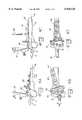
- FIG. 1is a fragmentary, perspective view of a wrist with an embodiment of a joint locator of the present invention engaged therewith;
- FIG. 2is a perspective view of the radius shown in FIG. 1, with the joint locator being attached to a T-template;
- FIG. 3is a perspective view of the joint locator and T-template shown in FIG. 2, and a saw blade positioned in association with a saw guide slot in the T-template;
- FIG. 4Ais a side view of the joint locator and T-template shown in FIG. 3, with an angular correction template being pivotally attached to the T-template after the saw cut has been made and prior to any angular correction;
- FIG. 4Bis a top view of the instrumentation of FIG. 4A;
- FIG. 4Cis a side view of the instrumentation of FIG. 4A after angular correction has been made and with a drill positioned above a drill guide in the angular correction template;
- FIG. 4Dis a top view of the instrumentation of FIG. 4C;
- FIG. 5is a perspective view of the fixating plate attached to the radius shown in FIGS. 4C and D, after use of the T-template and angular correction template;
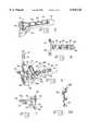
- FIG. 6is a perspective view of the joint locator and T-template shown in FIG. 2, with a radial shortening template attached to the T-template;
- FIG. 7is a top view of the T-template shown in FIG. 2;
- FIG. 8is a top view of the angular correction template shown in FIGS. 4A,B,C, and D;
- FIG. 8Ais a front view of the angular correction template shown in FIG. 8 with an additional locking screw shown.
- FIG. 9is a top view of the radial shortening template shown in FIG. 6;
- FIG. 9Ais a top view of an alternate radial shortening template which includes additional securing screws;
- FIG. 10is an elevational view of the joint locator shown in FIGS. 1-3, 4A,B,C,D and 6;
- FIG. 11is a side view of the joint locator shown in FIG. 10.
- Figs.show instrumentation adapted for use on a right wrist. It may be beneficial for certain of the instruments, such as the joint locator 10 and the first template 30 to be designed for use on a right wrist, with the corresponding instrument for a left wrist being a mirror image thereof.
- FIG. 1there is shown a fragmentary, perspective view of an embodiment of a joint locator 10 which is inserted into a joint space 12 in a wrist at an end of a radius 14.
- the radius 14includes a bearing surface 4 at the end thereof having a general orientation relative to a longitudinal axis 16 of radius 14.
- Joint locator 10includes a handle 18 and a bone engaging end 20 which is attached to and extends from handle 18 (shown in greater detail in FIGS. 10 and 11). Bone engaging end 20 is configured to engage the bearing surface 4 of radius 14 such that handle 18 is disposed at a corresponding orientation relative to the longitudinal axis 16, and thereby provides an indication of the orientation of the bearing surface relative to longitudinal axis 16.
- bone engaging end 20is in the form of two condyle shaped portions 22 each having a convex shape on one side which corresponds to the shape of the bearing surface on radius 14 for engagement therewith, and an oppositely located concave surface which corresponds to the shape of the mating carpus area bones.
- a notch 24is formed in handle 18 relatively closely adjacent to condyle shaped portions 22. Notch 24 is configured to engage radius 14 at a location on a periphery or rim of the bearing surface 4 of radius 14.
- handle 18provides a visual indication of the general orientation of the bearing surface relative to longitudinal axis 16.
- T-template 30includes an opening 32 for slidingly receiving joint locator 10.
- a thumbscrew 34 associated with opening 32is threadingly engaged with T-template 30 and locks joint locator 10 within opening 32.
- T-template 30 and joint locator 10thus coact with each other to position T-template 30 adjacent to the bearing surface at the end of radius 14.
- the locator handle 18may include a flat surface 19 which cooperates with flat surface 33 of opening 32.
- the flat surfaces 19 and 33are oriented relative the condyle shaped portion 22 which engages the bearing surface of the radius 14 to provide proper orientation of T-template 30 to the bearing surface 4.
- T-template 30also includes at least one hole 36 therein, and preferably includes three holes 36 as shown in FIGS. 2 and 3. T-template 30 is attached to the end of radius 14 using a plurality of fasteners or screws 38 which are received in respective holes 36. At a minimum, at least one screw 38 is used to attach T-template 30 to radius 14.
- T-template 30also includes a saw guide surface or slot 40 (FIGS. 2, 3 and 7) which is sized and configured for receiving a saw blade 42 therein.
- Saw blade 42is inserted into saw guide slot 40 (as indicated by directional arrow 44 in FIG. 3), and guides saw blade 42 through radius 14 (indicated by dashed lines 46 in FIG. 3).
- T-template 30also includes a pair of locating surfaces or slots 48 which are configured for attachment with other templates, as will be described in greater detail hereinafter.
- AC template 50is pivotally attached to T-template 30, whereby AC template 50 may be selectively positioned at one of a plurality of angular orientations relative to T-template 30 and is adjustably positioned to accommodate the radial deformity. More particularly, AC template 50 includes a pair of projections or pins 52 which are slidingly received along or within respective locating surfaces or slots 48 of T-template 30. Pins 52 may slide within locating slots 48 and allow pivotal movement between AC template 50 and T-template 30.
- AC template 50accommodates the changing angular orientation between the bearing surface 4 and the longitudinal axis of radius 14, thus allowing the AC template 50 to adjust to the proper position relative to the angularly corrected radius of FIGS. 4C and 4D.
- a thumbscrew 65 shown in FIG. 8Amay be provided on AC template 50 to engage slot 48 to secure the position of AC template 50 relative to first template 30, if desired.
- a second thumbscrew(not shown) may also be provided to engage the oppositely located slot 48, if desired.
- AC template 50also includes a plurality of drill guides 56 for guiding a drill 58 after the angular correction of radius 14 has been made.
- a plurality of holes 60 in AC template 50accommodate a clamp (not shown) which is used to clamp AC template 50 to radius 14 during a drilling operation with drill 58.
- the holes which are formed in radius 14 through holes 36 in T-template 30 and through drill guides 56 in AC template 50correspond to the hole pattern in a fixating plate 62 (FIG. 5) which is attached to radius 14 using a plurality of screws 64.
- a third or radial shortening (RS) template 70is shown in attachment with T-template 30.
- RS template 70includes a plurality of opposing pairs of projections 72, 74 and 76 which are slidingly received along or within respective locating surfaces or slots 48 of T-template 30.
- RS template 70also includes a second saw guide surface or slot 78 which is disposed in substantially parallel relationship to saw guide slot 40 when RS template is attached with T-template 30.
- Opposing pairs of projections 72, 74 and 76which form slots 73,75,77, allow RS template 70 to be attached to T-template 30 at a plurality of locations, whereby saw guide slot 78 may be selectively positioned relative to saw guide slot 40.
- First saw guide slot 40 and second saw guide slot 78guide a saw blade (such as shown in FIG. 3) through radius 14 (as indicated by dashed lines 80 in FIG. 6).
- RS template 70also includes a plurality of drill guides 82 for guiding a drill into radius 14 (such as drill 58 shown in FIG. 4C), and a plurality of holes 84 providing interconnection with a clamp (not shown) used to clamp RS template 70 to radius 14.
- Side drill guide holes 83are provided for drilling holes in bone for subsequent use with a bone clamp (not shown) to draw bone fragments together.
- joint locator 10is inserted into joint space 12 such that the convex condyle shaped portions 22 engage the bearing surface 4 at the end of radius 14.
- Notch 24provides clearance around the periphery of the bearing surface and is engaged with the periphery of the bearing surface.
- Handle 18provides a visual indication of the orientation of the bearing surface relative to the longitudinal axis 16 of radius 14. T-template 30 is then engaged with joint locator 10 such that handle 18 is received within opening 32 and locked into place using thumbscrew 34.
- At least one screw 38is then inserted through a corresponding hole 36 in T-template 30 and into radius 14 to attach T-template 30 at the end of radius 14 adjacent to the bearing surface. If an angular correction procedure is to be followed, a saw blade 42 is inserted into saw guide slot 40 and through radius 14.
- AC template 50is then attached to T-template 30, such that pins 52 are received within locating slots 48 as shown in FIGS. 4A and 4B.
- the distal end of the cut radius 14is rotated (in the direction of arrow 92 of FIG. 4A) to restore the proper volar tilt of approximately 10° as shown in FIG. 4C.
- the 10° volar tiltis angled distally relative to a line which is perpendicular to the longitudinal axis of radius 14.
- the distal end of the cut radiusis also rotated (for example, in the direction of arrow 94 of FIG. 4B) to align elongated portion 57 of AC template 50 with the axis 16 of radius 14 as shown in FIG. 4D.
- Thisprovides a radial correction in addition to the volar correction previously described. Aligning the elongated portion 57 to the axis 16 of radius 14 provides the proper radial correction. Ultimately, the amount of angular correction is determined by the judgment of the surgeon.
- At least one clamp(not shown) is engaged to a hole 60 in AC template 50 to clamp AC template 50 to radius 14, thus stabilizing the proper alignment of the bones. It is noted that upon securing the proper angular orientation of the bearing surface of the radius, the wrist will become properly aligned in all planes as evidenced by the proper alignment of the lunate bone 5 and capitate bone 6 with the radius 14, as shown in FIG. 4C.
- a drill 58is then inserted through drill guides 56 to form holes in radius 14 at particular locations corresponding to the pattern of the fixating plate 62.
- Joint locator 10, T-template 30 and AC template 50are then removed, and the bone graft 54 is placed into the resulting wedge shaped opening.
- a fixating plate 62is then attached to the radius by screws 64 utilizing the preformed holes therein. Any voids under the plate may be filled with bone graft, as appropriate.
- an RS template 70is slidingly engaged with and attached to T-template 30 at a particular location such that the second saw guide slot 78 in RS template 70 is disposed a predetermined distance away from the first saw guide slot 40 in T-template 30.
- the cutsare made in the radius through saw guide slots 40, 78, and the resulting free-floating piece of bone is removed. The thickness of bone removed is determined by which slot 73,75, or 77 is selected.
- RS template 70is clamped in place using at least one clamp (not shown) which engages one of the holes 84.
- Holesare formed in radius 14 by inserting a drill 58 through a plurality of drill guides 82 in RS template 70. Joint locator 10, T-template 30 and RS template 70 are then removed, the cut bone portions brought together, and a fixating plate with a corresponding hole pattern is attached to radius 14.
- FIG. 9AAn alternate RS template 71 is shown in FIG. 9A which provides a means of rigidly fixing the RS template 71 to T-template 30. Thumbscrews 88 are provided which threadingly engage the RS template 71 to secure the locating surface 49 of locating slot 48 in the desired slot of RS template 71.
- the T-template, AC template, RS template and joint locatorare preferably made of stainless steel, although any suitable material may be used. These components may be provided in various sizes as desired.
Landscapes
- Health & Medical Sciences (AREA)
- Surgery (AREA)
- Life Sciences & Earth Sciences (AREA)
- Biomedical Technology (AREA)
- Medical Informatics (AREA)
- Oral & Maxillofacial Surgery (AREA)
- Dentistry (AREA)
- Engineering & Computer Science (AREA)
- Veterinary Medicine (AREA)
- Heart & Thoracic Surgery (AREA)
- Nuclear Medicine, Radiotherapy & Molecular Imaging (AREA)
- Molecular Biology (AREA)
- Animal Behavior & Ethology (AREA)
- General Health & Medical Sciences (AREA)
- Public Health (AREA)
- Orthopedic Medicine & Surgery (AREA)
- Surgical Instruments (AREA)
Abstract
Description
Claims (34)
Priority Applications (1)
| Application Number | Priority Date | Filing Date | Title |
|---|---|---|---|
| US08/844,155US5935128A (en) | 1997-04-18 | 1997-04-18 | Orthopaedic template system including a joint locator |
Applications Claiming Priority (1)
| Application Number | Priority Date | Filing Date | Title |
|---|---|---|---|
| US08/844,155US5935128A (en) | 1997-04-18 | 1997-04-18 | Orthopaedic template system including a joint locator |
Publications (1)
| Publication Number | Publication Date |
|---|---|
| US5935128Atrue US5935128A (en) | 1999-08-10 |
Family
ID=25291967
Family Applications (1)
| Application Number | Title | Priority Date | Filing Date |
|---|---|---|---|
| US08/844,155Expired - Fee RelatedUS5935128A (en) | 1997-04-18 | 1997-04-18 | Orthopaedic template system including a joint locator |
Country Status (1)
| Country | Link |
|---|---|
| US (1) | US5935128A (en) |
Cited By (109)
| Publication number | Priority date | Publication date | Assignee | Title |
|---|---|---|---|---|
| US6283969B1 (en) | 2000-03-10 | 2001-09-04 | Wright Medical Technology, Inc. | Bone plating system |
| US6342057B1 (en) | 2000-04-28 | 2002-01-29 | Synthes (Usa) | Remotely aligned surgical drill guide |
| US6379364B1 (en) | 2000-04-28 | 2002-04-30 | Synthes (Usa) | Dual drill guide for a locking bone plate |
| US20030105461A1 (en)* | 2001-11-30 | 2003-06-05 | Putnam Matthew D. | Wrist surgery devices and techniques |
| US20030171757A1 (en)* | 2002-03-05 | 2003-09-11 | Coon Thomas M. | Minimally invasive total knee arthroplasty method and instrumentation |
| US20030216741A1 (en)* | 2001-06-20 | 2003-11-20 | Sanford Adam H. | Method and apparatus for resecting a distal femur and a proximal tibia in preparation for implementing a partial knee prosthesis |
| US20050171548A1 (en)* | 2003-11-18 | 2005-08-04 | Kelman David C. | Surgical technique and instrumentation for minimal incision hip arthroplasty surgery |
| US20060149287A1 (en)* | 2003-03-11 | 2006-07-06 | Stephane Lavallee | Instrument for fixing the position of a cutting plane |
| US20070055270A1 (en)* | 2004-05-19 | 2007-03-08 | Howmedica Osteonics Corp. | Navigated lateral /medial femoral resection guide |
| US7237556B2 (en) | 2002-02-11 | 2007-07-03 | Smith & Nephew, Inc. | Image-guided fracture reduction |
| US20070173854A1 (en)* | 2006-01-23 | 2007-07-26 | Berger Richard A | Bone resection apparatus and method for knee surgery |
| US20070270850A1 (en)* | 2006-04-28 | 2007-11-22 | Geissler William B | Osteotomy systems |
| US20080147073A1 (en)* | 2005-01-31 | 2008-06-19 | Ammann Kelly G | Method and apparatus for performing an open wedge, high tibial osteotomy |
| US20080172056A1 (en)* | 2007-01-17 | 2008-07-17 | Edwards Scott G | System and method for bone shortening |
| US20080177293A1 (en)* | 2006-10-23 | 2008-07-24 | Warsaw Orthopedic, Inc. | Method and apparatus for osteochondral autograft transplantation |
| US7425213B2 (en) | 2002-12-10 | 2008-09-16 | Depuy Products, Inc. | Method of endosteal nailing |
| US20080255582A1 (en)* | 2007-04-11 | 2008-10-16 | Harris John F | Methods and Template Assembly for Implanting an Electrode Array in a Patient |
| US7477926B2 (en) | 2004-03-31 | 2009-01-13 | Smith & Nephew, Inc. | Methods and apparatuses for providing a reference array input device |
| US7527639B2 (en) | 2000-02-01 | 2009-05-05 | Depuy Products, Inc. | Fixation system with multidirectional bone supports |
| US20090118768A1 (en)* | 2007-11-02 | 2009-05-07 | Sixto Jr Robert | Elbow Fracture Fixation System |
| US7547307B2 (en) | 2001-02-27 | 2009-06-16 | Smith & Nephew, Inc. | Computer assisted knee arthroplasty instrumentation, systems, and processes |
| EP1779797A3 (en)* | 2005-02-25 | 2009-06-24 | Precimed S.A. | Plate and template for canine humeral osteotomy |
| US7563263B2 (en) | 2000-02-01 | 2009-07-21 | Depuy Products, Inc. | Intramedullary fixation device for metaphyseal long bone fractures |
| US20090275987A1 (en)* | 2008-05-02 | 2009-11-05 | Thomas James Graham | Bone plate extender and extension system for bone restoration and methods of use thereof |
| US20090275947A1 (en)* | 2008-05-02 | 2009-11-05 | Thomas James Graham | Bone plate system for bone restoration and methods of use thereof |
| US20090281577A1 (en)* | 2008-05-08 | 2009-11-12 | Thomas James Graham | Bone plate with reduction aids and methods of use thereof |
| US20090312802A1 (en)* | 2007-09-13 | 2009-12-17 | Dasilva Manuel | System for making a bone repair |
| US7695502B2 (en) | 2000-02-01 | 2010-04-13 | Depuy Products, Inc. | Bone stabilization system including plate having fixed-angle holes together with unidirectional locking screws and surgeon-directed locking screws |
| US20100121331A1 (en)* | 2003-11-18 | 2010-05-13 | Sharp Jeffrey A | Universal double offset surgical instrument |
| US7727264B2 (en) | 2000-02-01 | 2010-06-01 | Depuy Products, Inc. | Intramedullary fixation device for metaphyseal long bone fractures |
| US7764985B2 (en) | 2003-10-20 | 2010-07-27 | Smith & Nephew, Inc. | Surgical navigation system component fault interfaces and related processes |
| US20100191244A1 (en)* | 2007-03-23 | 2010-07-29 | Derrick White | Surgical templates |
| US7794467B2 (en) | 2003-11-14 | 2010-09-14 | Smith & Nephew, Inc. | Adjustable surgical cutting systems |
| US7857838B2 (en) | 2003-03-27 | 2010-12-28 | Depuy Products, Inc. | Anatomical distal radius fracture fixation plate |
| US7862570B2 (en) | 2003-10-03 | 2011-01-04 | Smith & Nephew, Inc. | Surgical positioners |
| US7905909B2 (en) | 2005-09-19 | 2011-03-15 | Depuy Products, Inc. | Bone stabilization system including multi-directional threaded fixation element |
| US20110106081A1 (en)* | 2008-05-08 | 2011-05-05 | Thomas James Graham | Bone Plate with Flange Member and Methods of Use Thereof |
| US8109942B2 (en) | 2004-04-21 | 2012-02-07 | Smith & Nephew, Inc. | Computer-aided methods, systems, and apparatuses for shoulder arthroplasty |
| US8177788B2 (en) | 2005-02-22 | 2012-05-15 | Smith & Nephew, Inc. | In-line milling system |
| US20120130383A1 (en)* | 2010-11-18 | 2012-05-24 | Budoff Jeffrey E | Method of performing osteotomy |
| US20120191199A1 (en)* | 2010-12-17 | 2012-07-26 | Michael Raemisch | Method and apparatus for distal radioulnar joint (druj) arthroplasty |
| US8545540B2 (en) | 2004-12-14 | 2013-10-01 | Biomet C.V. | Bone plate with pre-assembled drill guide tips |
| US8591554B2 (en) | 2010-05-07 | 2013-11-26 | Osteomed Llc | System for treating bone fractures |
| US20140180342A1 (en)* | 2012-08-30 | 2014-06-26 | Wright Medical Technology, Inc. | Implant for osteotomy, tool for inserting the implant, and method of inserting the implant using the tool |
| US8771279B2 (en) | 2005-01-31 | 2014-07-08 | Arthrex, Inc. | Method and apparatus for performing an osteotomy in bone |
| US8784495B2 (en) | 2000-01-14 | 2014-07-22 | Bonutti Skeletal Innovations Llc | Segmental knee arthroplasty |
| US8834490B2 (en) | 2001-08-28 | 2014-09-16 | Bonutti Skeletal Innovations Llc | Method for robotic arthroplasty using navigation |
| US8852197B2 (en) | 2011-06-30 | 2014-10-07 | Depuy (Ireland) | Surgical instrument assemblies for use in surgically preparing a tibia for implantation of a prosthetic component |
| US8858562B2 (en) | 2006-03-20 | 2014-10-14 | Biomet C.V. | Bone plate shaping system |
| US8858602B2 (en) | 2011-02-01 | 2014-10-14 | Nextremity Solutions, Inc. | Bone defect repair device and method |
| US8926619B2 (en) | 2011-06-30 | 2015-01-06 | Depuy (Ireland) | Method of surgically preparing a tibia for implantation of a prosthetic component |
| US8939986B2 (en) | 2011-06-30 | 2015-01-27 | Depuy (Ireland) | Surgical instruments for use in surgically preparing a tibia for implantation of a prosthetic component |
| US8951301B2 (en) | 2011-06-30 | 2015-02-10 | Depuy (Ireland) | Method of using a trialing system for a knee prosthesis |
| US8968412B2 (en) | 2011-06-30 | 2015-03-03 | Depuy (Ireland) | Trialing system for a knee prosthesis and method of use |
| US8986390B2 (en) | 2011-06-30 | 2015-03-24 | Depuy (Ireland) | Method of trialing a knee prosthesis |
| US9050151B2 (en) | 2012-03-06 | 2015-06-09 | Stryker Trauma Sa | Bone plate and aiming block |
| US9114012B2 (en) | 2011-06-30 | 2015-08-25 | Depuy (Ireland) | Femoral trial component |
| US20150320430A1 (en)* | 2014-05-12 | 2015-11-12 | Biomet Manufacturing, Llc | Humeral Cut Guide |
| US9259591B2 (en) | 2007-12-28 | 2016-02-16 | Cyberonics, Inc. | Housing for an implantable medical device |
| EP3000416A3 (en)* | 2000-03-10 | 2016-08-17 | Smith & Nephew, Inc. | Apparatus for use in arthroplasty on a knee joint |
| US9622805B2 (en) | 2015-08-14 | 2017-04-18 | Treace Medical Concepts, Inc. | Bone positioning and preparing guide systems and methods |
| WO2017064290A1 (en)* | 2015-10-14 | 2017-04-20 | Surgivisio | Device for minimally invasive attachment of a tracker and/or a registration phantom to a patient's bone |
| US9687250B2 (en) | 2015-01-07 | 2017-06-27 | Treace Medical Concepts, Inc. | Bone cutting guide systems and methods |
| EP3091911A4 (en)* | 2014-01-07 | 2017-09-20 | Nextremity Solutions, Inc. | Resection guides, implants and methods |
| US9833270B2 (en) | 2013-09-19 | 2017-12-05 | Mcginley Engineered Solutions, Llc | Variable angle blade plate system and method |
| US20170360453A1 (en)* | 2016-06-17 | 2017-12-21 | Socovar, L.P. | Limb sparing in mammals using patient-specific endoprostheses and cutting guides. |
| US9861491B2 (en) | 2014-04-30 | 2018-01-09 | Depuy Ireland Unlimited Company | Tibial trial system for a knee prosthesis |
| EP3185796A4 (en)* | 2014-08-28 | 2018-05-02 | Nextremity Solutions, Inc. | Proximal bunion resection guides and plates and methods of use |
| JP2018528008A (en)* | 2015-09-18 | 2018-09-27 | トリース メディカル コンセプツ,インコーポレイティド | Joint spacer system and method |
| US10195056B2 (en) | 2015-10-19 | 2019-02-05 | Depuy Ireland Unlimited Company | Method for preparing a patient's tibia to receive an implant |
| WO2019038240A1 (en)* | 2017-08-22 | 2019-02-28 | Newclip International | Surgical guide device for assisting an open wedge osteotomy |
| US10342590B2 (en) | 2015-08-14 | 2019-07-09 | Treace Medical Concepts, Inc. | Tarsal-metatarsal joint procedure utilizing fulcrum |
| US10512470B1 (en) | 2016-08-26 | 2019-12-24 | Treace Medical Concepts, Inc. | Osteotomy procedure for correcting bone misalignment |
| US10524808B1 (en) | 2016-11-11 | 2020-01-07 | Treace Medical Concepts, Inc. | Devices and techniques for performing an osteotomy procedure on a first metatarsal to correct a bone misalignment |
| US10537445B2 (en) | 2015-10-19 | 2020-01-21 | Depuy Ireland Unlimited Company | Surgical instruments for preparing a patient's tibia to receive an implant |
| US10555757B2 (en) | 2014-07-15 | 2020-02-11 | Treace Medical Concepts, Inc. | Bone positioning and cutting system and method |
| US10653467B2 (en) | 2015-05-06 | 2020-05-19 | Treace Medical Concepts, Inc. | Intra-osseous plate system and method |
| US10849663B2 (en) | 2015-07-14 | 2020-12-01 | Treace Medical Concepts, Inc. | Bone cutting guide systems and methods |
| US10849631B2 (en) | 2015-02-18 | 2020-12-01 | Treace Medical Concepts, Inc. | Pivotable bone cutting guide useful for bone realignment and compression techniques |
| US10874446B2 (en) | 2015-07-14 | 2020-12-29 | Treace Medical Concepts, Inc. | Bone positioning guide |
| US10939939B1 (en) | 2017-02-26 | 2021-03-09 | Treace Medical Concepts, Inc. | Fulcrum for tarsal-metatarsal joint procedure |
| US11278337B2 (en) | 2015-08-14 | 2022-03-22 | Treace Medical Concepts, Inc. | Tarsal-metatarsal joint procedure utilizing fulcrum |
| US11278355B2 (en)* | 2015-10-14 | 2022-03-22 | Ecential Robotics | Modular fluoro-navigation instrument |
| US11406317B2 (en) | 2007-12-28 | 2022-08-09 | Livanova Usa, Inc. | Method for detecting neurological and clinical manifestations of a seizure |
| US11583323B2 (en) | 2018-07-12 | 2023-02-21 | Treace Medical Concepts, Inc. | Multi-diameter bone pin for installing and aligning bone fixation plate while minimizing bone damage |
| US11596443B2 (en) | 2018-07-11 | 2023-03-07 | Treace Medical Concepts, Inc. | Compressor-distractor for angularly realigning bone portions |
| US11602354B2 (en)* | 2016-06-21 | 2023-03-14 | 3D Metal Printing Limited | Surgical assembly, stabilisation plate and methods |
| US11607250B2 (en) | 2019-02-13 | 2023-03-21 | Treace Medical Concepts, Inc. | Tarsal-metatarsal joint procedure utilizing compressor-distractor and instrument providing sliding surface |
| US11622797B2 (en) | 2020-01-31 | 2023-04-11 | Treace Medical Concepts, Inc. | Metatarsophalangeal joint preparation and metatarsal realignment for fusion |
| US11627954B2 (en) | 2019-08-07 | 2023-04-18 | Treace Medical Concepts, Inc. | Bi-planar instrument for bone cutting and joint realignment procedure |
| USD1011524S1 (en) | 2022-02-23 | 2024-01-16 | Treace Medical Concepts, Inc. | Compressor-distractor for the foot |
| US11889998B1 (en) | 2019-09-12 | 2024-02-06 | Treace Medical Concepts, Inc. | Surgical pin positioning lock |
| US11890039B1 (en) | 2019-09-13 | 2024-02-06 | Treace Medical Concepts, Inc. | Multi-diameter K-wire for orthopedic applications |
| US11931106B2 (en) | 2019-09-13 | 2024-03-19 | Treace Medical Concepts, Inc. | Patient-specific surgical methods and instrumentation |
| US11986251B2 (en) | 2019-09-13 | 2024-05-21 | Treace Medical Concepts, Inc. | Patient-specific osteotomy instrumentation |
| US20240164792A1 (en)* | 2022-11-18 | 2024-05-23 | Karl Leibinger Medizintechnik Gmbh & Co. Kg | Resection template for the resection of a bone |
| US12004789B2 (en) | 2020-05-19 | 2024-06-11 | Treace Medical Concepts, Inc. | Devices and techniques for treating metatarsus adductus |
| US20240252181A1 (en)* | 2023-01-30 | 2024-08-01 | Treace Medical Concepts, Inc. | Apparatus, system, and method for instrumentation |
| USD1051382S1 (en) | 2022-02-23 | 2024-11-12 | Treace Medical Concepts, Inc. | Lesser metatarsal cut guide |
| US12161371B2 (en) | 2021-01-18 | 2024-12-10 | Treace Medical Concepts, Inc. | Contoured bone plate with locking screw for bone compression, particularly across a tarsometatarsal joint |
| WO2024254647A1 (en)* | 2023-06-16 | 2024-12-19 | Personalised Surgery Pty Ltd | Surgical guide device |
| USD1057155S1 (en) | 2022-02-23 | 2025-01-07 | Treace Medical Concepts, Inc. | Lesser metatarsal cut guide with parallel cut faces |
| US12193683B2 (en) | 2021-05-20 | 2025-01-14 | Treace Medical Concepts, Inc. | Cut guide with integrated joint realignment features |
| USD1068078S1 (en) | 2023-02-08 | 2025-03-25 | Treace Medical Concepts, Inc. | Handle for an orthopedic instrument |
| USD1068077S1 (en) | 2023-02-08 | 2025-03-25 | Treace Medical Concepts, Inc. | Orthopedic rasp for preparing an intercuneiform joint |
| USD1075012S1 (en) | 2022-02-23 | 2025-05-13 | Treace Medical Concepts, Inc. | Metatarsal lateral release instrument |
| US12310603B2 (en) | 2021-02-18 | 2025-05-27 | Treace Medical Concepts, Inc. | System and technique for metatarsal realignment with reduced incision length |
| USD1079011S1 (en) | 2022-02-23 | 2025-06-10 | Treace Medical Concepts, Inc. | Metatarsal cut guide with parallel cut faces |
| US12440250B2 (en) | 2024-02-05 | 2025-10-14 | Treace Medical Concepts, Inc. | Multi-diameter K-wire for orthopedic applications |
Citations (20)
| Publication number | Priority date | Publication date | Assignee | Title |
|---|---|---|---|---|
| US4565191A (en)* | 1984-01-12 | 1986-01-21 | Slocum D Barclay | Apparatus and method for performing cuneiform osteotomy |
| EP0340176A2 (en)* | 1988-04-29 | 1989-11-02 | G. CREMASCOLI S.p.A. | Device for the resection of a femoral bone for the application of knee articulation prostheses |
| US4929247A (en)* | 1988-10-06 | 1990-05-29 | Rayhack John M | Bone compression and distraction device |
| EP0380451A2 (en)* | 1989-01-11 | 1990-08-01 | G. CREMASCOLI S.p.A. | Apparatus for resecting femurs and applying knee articulation prostheses |
| US5006120A (en)* | 1989-10-10 | 1991-04-09 | Carter Peter R | Distal radial fracture set and method for repairing distal radial fractures |
| US5021056A (en)* | 1989-09-14 | 1991-06-04 | Intermedics Orthopedics, Inc. | Upper tibial osteotomy system |
| US5042983A (en)* | 1989-10-30 | 1991-08-27 | Rayhack John M | Precision bone cutting guide |
| US5049149A (en)* | 1988-12-14 | 1991-09-17 | Joachim Schmidt | Sawing gauge system |
| US5053039A (en)* | 1989-09-14 | 1991-10-01 | Intermedics Orthopedics | Upper tibial osteotomy system |
| US5078719A (en)* | 1990-01-08 | 1992-01-07 | Schreiber Saul N | Osteotomy device and method therefor |
| EP0466659A2 (en)* | 1990-06-22 | 1992-01-15 | G. Cremascoli S.R.L. | Apparatus for resecting the femoral and tibial bones for fitting knee articulation prostheses |
| US5112334A (en)* | 1990-10-25 | 1992-05-12 | Alchermes Stephen L | Surgical instrument for facilitating accurate osteotomy cuts in bone and method for utilizing same |
| US5147364A (en)* | 1981-08-20 | 1992-09-15 | Ohio Medical Instrument Company | Osteotomy saw/file, cutting guide and method |
| US5176685A (en)* | 1989-10-30 | 1993-01-05 | Rayhack John M | Precision bone cutting guide |
| EP0538153A1 (en)* | 1991-10-01 | 1993-04-21 | Impact | Modular auxiliary instrument for the implantation of a knee prosthesis |
| US5254119A (en)* | 1991-08-23 | 1993-10-19 | Schreiber Saul N | Osteotomy device and method therefor |
| US5364402A (en)* | 1993-07-29 | 1994-11-15 | Intermedics Orthopedics, Inc. | Tibial spacer saw guide |
| US5413579A (en)* | 1992-05-03 | 1995-05-09 | Technology Finance Corporation (Proprietary) Limited | Surgical saw guide and drill guide |
| US5540695A (en)* | 1994-02-18 | 1996-07-30 | Howmedica Inc. | Osteotomy cutting guide |
| US5569260A (en)* | 1994-12-01 | 1996-10-29 | Petersen; Thomas D. | Distal femoral resector guide |
- 1997
- 1997-04-18USUS08/844,155patent/US5935128A/ennot_activeExpired - Fee Related
Patent Citations (21)
| Publication number | Priority date | Publication date | Assignee | Title |
|---|---|---|---|---|
| US5147364A (en)* | 1981-08-20 | 1992-09-15 | Ohio Medical Instrument Company | Osteotomy saw/file, cutting guide and method |
| US4565191A (en)* | 1984-01-12 | 1986-01-21 | Slocum D Barclay | Apparatus and method for performing cuneiform osteotomy |
| EP0340176A2 (en)* | 1988-04-29 | 1989-11-02 | G. CREMASCOLI S.p.A. | Device for the resection of a femoral bone for the application of knee articulation prostheses |
| US4929247A (en)* | 1988-10-06 | 1990-05-29 | Rayhack John M | Bone compression and distraction device |
| US5049149A (en)* | 1988-12-14 | 1991-09-17 | Joachim Schmidt | Sawing gauge system |
| EP0380451A2 (en)* | 1989-01-11 | 1990-08-01 | G. CREMASCOLI S.p.A. | Apparatus for resecting femurs and applying knee articulation prostheses |
| US5021056A (en)* | 1989-09-14 | 1991-06-04 | Intermedics Orthopedics, Inc. | Upper tibial osteotomy system |
| US5053039A (en)* | 1989-09-14 | 1991-10-01 | Intermedics Orthopedics | Upper tibial osteotomy system |
| US5006120A (en)* | 1989-10-10 | 1991-04-09 | Carter Peter R | Distal radial fracture set and method for repairing distal radial fractures |
| US5042983A (en)* | 1989-10-30 | 1991-08-27 | Rayhack John M | Precision bone cutting guide |
| US5176685A (en)* | 1989-10-30 | 1993-01-05 | Rayhack John M | Precision bone cutting guide |
| US5078719A (en)* | 1990-01-08 | 1992-01-07 | Schreiber Saul N | Osteotomy device and method therefor |
| EP0466659A2 (en)* | 1990-06-22 | 1992-01-15 | G. Cremascoli S.R.L. | Apparatus for resecting the femoral and tibial bones for fitting knee articulation prostheses |
| US5112334A (en)* | 1990-10-25 | 1992-05-12 | Alchermes Stephen L | Surgical instrument for facilitating accurate osteotomy cuts in bone and method for utilizing same |
| US5254119A (en)* | 1991-08-23 | 1993-10-19 | Schreiber Saul N | Osteotomy device and method therefor |
| EP0538153A1 (en)* | 1991-10-01 | 1993-04-21 | Impact | Modular auxiliary instrument for the implantation of a knee prosthesis |
| US5413579A (en)* | 1992-05-03 | 1995-05-09 | Technology Finance Corporation (Proprietary) Limited | Surgical saw guide and drill guide |
| US5470335A (en)* | 1992-05-03 | 1995-11-28 | Technology Finance Corporation (Proprietary) Limited | Method for carrying out an osteotomy procedure |
| US5364402A (en)* | 1993-07-29 | 1994-11-15 | Intermedics Orthopedics, Inc. | Tibial spacer saw guide |
| US5540695A (en)* | 1994-02-18 | 1996-07-30 | Howmedica Inc. | Osteotomy cutting guide |
| US5569260A (en)* | 1994-12-01 | 1996-10-29 | Petersen; Thomas D. | Distal femoral resector guide |
Non-Patent Citations (12)
| Title |
|---|
| "Biomechanics of Ulnar Osteotomies and Plate Fixation"--Rayhack et al--Clin & Lab Perform of Bone Plates--1994. |
| Biomechanics of Ulnar Osteotomies and Plate Fixation Rayhack et al Clin & Lab Perform of Bone Plates 1994.* |
| Forte Distal Radial Plate System Zimmer, Inc. c1994 Literature No. 97 2480 00.* |
| Forte Distal Radial Plate System--Zimmer, Inc.--c1994--Literature No. 97-2480-00. |
| Osteotomy System The Complete Knee Solution Zimmer, Inc. c1994 Literature No. 97 5250 101.* |
| Osteotomy System-The Complete Knee Solution--Zimmer, Inc.--c1994--Literature No. 97-5250-101. |
| Rayhack Osteotomy System Radial Shortening in Kienb o ck s Disease Creative Medical Designs, Inc. Sep. 1, 1995.* |
| Rayhack Osteotomy Systems Rayhack Radial Distractor Creative Medical Designs, Inc. No date available.* |
| Rayhack Osteotomy Systems™--Rayhack Radial Distractor--Creative Medical Designs, Inc.--No date available. |
| Rayhack Osteotomy System™--Radial Shortening in Kienbock's Disease--Creative Medical Designs, Inc.--Sep. 1, 1995. |
| ROS System Rayhack Osteotomy System Terray Corporation No date available.* |
| ROS™ System--Rayhack Osteotomy System--Terray Corporation--No date available. |
Cited By (264)
| Publication number | Priority date | Publication date | Assignee | Title |
|---|---|---|---|---|
| US9795394B2 (en) | 2000-01-14 | 2017-10-24 | Bonutti Skeletal Innovations Llc | Method for placing implant using robotic system |
| US9192459B2 (en) | 2000-01-14 | 2015-11-24 | Bonutti Skeletal Innovations Llc | Method of performing total knee arthroplasty |
| US8784495B2 (en) | 2000-01-14 | 2014-07-22 | Bonutti Skeletal Innovations Llc | Segmental knee arthroplasty |
| US9101443B2 (en) | 2000-01-14 | 2015-08-11 | Bonutti Skeletal Innovations Llc | Methods for robotic arthroplasty |
| US7563263B2 (en) | 2000-02-01 | 2009-07-21 | Depuy Products, Inc. | Intramedullary fixation device for metaphyseal long bone fractures |
| US9572609B2 (en) | 2000-02-01 | 2017-02-21 | Biomet C.V. | Method of using a volar bone plate on a fracture |
| US7780711B2 (en) | 2000-02-01 | 2010-08-24 | Depuy Products, Inc. | Fixation system with multidirectional bone supports |
| US9480512B2 (en) | 2000-02-01 | 2016-11-01 | Biomet C.V. | Volar fixation system with fixed-angle multi-hole drill guide |
| US7527639B2 (en) | 2000-02-01 | 2009-05-05 | Depuy Products, Inc. | Fixation system with multidirectional bone supports |
| US7727264B2 (en) | 2000-02-01 | 2010-06-01 | Depuy Products, Inc. | Intramedullary fixation device for metaphyseal long bone fractures |
| US7695502B2 (en) | 2000-02-01 | 2010-04-13 | Depuy Products, Inc. | Bone stabilization system including plate having fixed-angle holes together with unidirectional locking screws and surgeon-directed locking screws |
| US9492213B2 (en) | 2000-02-01 | 2016-11-15 | Biomet C.V. | Volar fixation system |
| US8403967B2 (en) | 2000-02-01 | 2013-03-26 | Biomet C.V. | Volar fixation system and methods of using the same |
| US6283969B1 (en) | 2000-03-10 | 2001-09-04 | Wright Medical Technology, Inc. | Bone plating system |
| EP3000416A3 (en)* | 2000-03-10 | 2016-08-17 | Smith & Nephew, Inc. | Apparatus for use in arthroplasty on a knee joint |
| EP1132052A2 (en) | 2000-03-10 | 2001-09-12 | Wright Medical Technology, Inc. | Bone plating system |
| US6379364B1 (en) | 2000-04-28 | 2002-04-30 | Synthes (Usa) | Dual drill guide for a locking bone plate |
| US6342057B1 (en) | 2000-04-28 | 2002-01-29 | Synthes (Usa) | Remotely aligned surgical drill guide |
| US7547307B2 (en) | 2001-02-27 | 2009-06-16 | Smith & Nephew, Inc. | Computer assisted knee arthroplasty instrumentation, systems, and processes |
| US20030216741A1 (en)* | 2001-06-20 | 2003-11-20 | Sanford Adam H. | Method and apparatus for resecting a distal femur and a proximal tibia in preparation for implementing a partial knee prosthesis |
| US7285122B2 (en)* | 2001-06-20 | 2007-10-23 | Zimmer, Inc. | Method and apparatus for resecting a distal femur and a proximal tibia in preparation for implementing a partial knee prosthesis |
| US10321918B2 (en) | 2001-08-28 | 2019-06-18 | Bonutti Skeletal Innovations Llc | Methods for robotic surgery using a cannula |
| US8834490B2 (en) | 2001-08-28 | 2014-09-16 | Bonutti Skeletal Innovations Llc | Method for robotic arthroplasty using navigation |
| US10470780B2 (en) | 2001-08-28 | 2019-11-12 | Bonutti Skeletal Innovations Llc | Systems and methods for ligament balancing in robotic surgery |
| US8858557B2 (en) | 2001-08-28 | 2014-10-14 | Bonutti Skeletal Innovations Llc | Method of preparing a femur and tibia in knee arthroplasty |
| US10231739B1 (en) | 2001-08-28 | 2019-03-19 | Bonutti Skeletal Innovations Llc | System and method for robotic surgery |
| US9060797B2 (en) | 2001-08-28 | 2015-06-23 | Bonutti Skeletal Innovations Llc | Method of preparing a femur and tibia in knee arthroplasty |
| US9763683B2 (en) | 2001-08-28 | 2017-09-19 | Bonutti Skeletal Innovations Llc | Method for performing surgical procedures using optical cutting guides |
| US8840629B2 (en) | 2001-08-28 | 2014-09-23 | Bonutti Skeletal Innovations Llc | Robotic arthroplasty system including navigation |
| US20030105461A1 (en)* | 2001-11-30 | 2003-06-05 | Putnam Matthew D. | Wrist surgery devices and techniques |
| US6755831B2 (en)* | 2001-11-30 | 2004-06-29 | Regents Of The University Of Minnesota | Wrist surgery devices and techniques |
| US7237556B2 (en) | 2002-02-11 | 2007-07-03 | Smith & Nephew, Inc. | Image-guided fracture reduction |
| JP2006504442A (en)* | 2002-03-05 | 2006-02-09 | ネムコムド リミテッド | Total knee arthroplasty methods and instruments to minimize injury |
| US7172596B2 (en)* | 2002-03-05 | 2007-02-06 | Coon Thomas M | Minimally invasive total knee arthroplasty method and instrumentation |
| US20030171757A1 (en)* | 2002-03-05 | 2003-09-11 | Coon Thomas M. | Minimally invasive total knee arthroplasty method and instrumentation |
| US20050273115A1 (en)* | 2002-03-05 | 2005-12-08 | Coon Thomas M | Minimally invasive total-knee arthroplasty method and instrumentation |
| US7425213B2 (en) | 2002-12-10 | 2008-09-16 | Depuy Products, Inc. | Method of endosteal nailing |
| US7780664B2 (en) | 2002-12-10 | 2010-08-24 | Depuy Products, Inc. | Endosteal nail |
| US20060149287A1 (en)* | 2003-03-11 | 2006-07-06 | Stephane Lavallee | Instrument for fixing the position of a cutting plane |
| US7691108B2 (en)* | 2003-03-11 | 2010-04-06 | Perception Raisonnement Action En Medecine | Instrument for locating the position of a cutting plane |
| US8579946B2 (en) | 2003-03-27 | 2013-11-12 | Biomet C.V. | Anatomical distal radius fracture fixation plate |
| US7857838B2 (en) | 2003-03-27 | 2010-12-28 | Depuy Products, Inc. | Anatomical distal radius fracture fixation plate |
| US9072558B2 (en) | 2003-09-17 | 2015-07-07 | Biomet C.V. | Distal radius fracture fixation plate with ulnar buttress |
| US8556945B2 (en) | 2003-09-17 | 2013-10-15 | Biomet C.V. | Anatomical distal radius fracture fixation plate with ulnar buttress |
| US8491597B2 (en) | 2003-10-03 | 2013-07-23 | Smith & Nephew, Inc. (partial interest) | Surgical positioners |
| US7862570B2 (en) | 2003-10-03 | 2011-01-04 | Smith & Nephew, Inc. | Surgical positioners |
| US7764985B2 (en) | 2003-10-20 | 2010-07-27 | Smith & Nephew, Inc. | Surgical navigation system component fault interfaces and related processes |
| US7794467B2 (en) | 2003-11-14 | 2010-09-14 | Smith & Nephew, Inc. | Adjustable surgical cutting systems |
| US9526512B2 (en) | 2003-11-18 | 2016-12-27 | Smith & Nephew, Inc. | Universal double offset surgical instrument |
| US10292715B2 (en) | 2003-11-18 | 2019-05-21 | Smith & Nephew, Inc. | Surgical technique and instrumentation for minimal incision hip arthroplasty surgery |
| US8734451B2 (en) | 2003-11-18 | 2014-05-27 | Smith & Nephew, Inc. | Surgical technique and instrumentation for minimal hip arthroplasty surgery |
| US20050171548A1 (en)* | 2003-11-18 | 2005-08-04 | Kelman David C. | Surgical technique and instrumentation for minimal incision hip arthroplasty surgery |
| US20100121331A1 (en)* | 2003-11-18 | 2010-05-13 | Sharp Jeffrey A | Universal double offset surgical instrument |
| US8657824B2 (en) | 2003-11-18 | 2014-02-25 | Smith & Nephew, Inc. | Universal double offset surgical instrument |
| USD648850S1 (en) | 2003-11-18 | 2011-11-15 | Smith & Nephew, Inc. | Surgical hip anterior approach arthroplasty device |
| US9615837B2 (en) | 2003-11-18 | 2017-04-11 | Smith & Nephew, Inc. | Surgical technique and instrumentation for minimal incision hip arthroplasty surgery |
| US11219467B2 (en) | 2003-11-18 | 2022-01-11 | Smith & Nephew, Inc. | Surgical technique and instrumentation for minimal incision hip arthroplasty surgery |
| US7591821B2 (en) | 2003-11-18 | 2009-09-22 | Smith & Nephew, Inc. | Surgical technique and instrumentation for minimal incision hip arthroplasty surgery |
| US20090275948A1 (en)* | 2003-11-18 | 2009-11-05 | Smith & Nephew, Inc. | Surgical technique and instrumentation for minimal incision hip arthroplasty surgery |
| US11957363B2 (en) | 2003-11-18 | 2024-04-16 | Smith & Nephew, Inc. | Surgical technique and instrumentation for minimal incision hip arthroplasty surgery |
| US9622758B2 (en) | 2003-11-18 | 2017-04-18 | Smith & Nephew, Inc. | Surgical technique and instrumentation for minimal incision hip arthroplasty surgery |
| US8096993B2 (en) | 2003-11-18 | 2012-01-17 | Smith & Nephew, Inc. | Surgical technique and instrumentation for minimal incision hip arthroplasty surgery |
| USD677384S1 (en) | 2003-11-18 | 2013-03-05 | Smith & Nephew, Inc. | Surgical hip anterior approach arthroplasty device |
| US9265508B2 (en) | 2003-11-18 | 2016-02-23 | Smith & Nephew, Inc. | Surgical technique and instrumentation for minimal incision hip arthroplasty surgery |
| US7477926B2 (en) | 2004-03-31 | 2009-01-13 | Smith & Nephew, Inc. | Methods and apparatuses for providing a reference array input device |
| US8109942B2 (en) | 2004-04-21 | 2012-02-07 | Smith & Nephew, Inc. | Computer-aided methods, systems, and apparatuses for shoulder arthroplasty |
| US8075566B2 (en) | 2004-05-19 | 2011-12-13 | Howmedica Osteonics Corp. | Navigated lateral/medial femoral resection guide |
| US20070123900A1 (en)* | 2004-05-19 | 2007-05-31 | Howmedica Osteonics Corp. | Navigated lateral/medial femoral resection guide |
| US7998142B2 (en) | 2004-05-19 | 2011-08-16 | Howmedica Osteonics Corp. | Navigated lateral/medial femoral resection guide |
| US20070055270A1 (en)* | 2004-05-19 | 2007-03-08 | Howmedica Osteonics Corp. | Navigated lateral /medial femoral resection guide |
| US8545540B2 (en) | 2004-12-14 | 2013-10-01 | Biomet C.V. | Bone plate with pre-assembled drill guide tips |
| US9220515B2 (en) | 2004-12-14 | 2015-12-29 | Biomet C.V. | Bone plate with pre-assembled drill guide tips |
| US9370376B2 (en) | 2004-12-14 | 2016-06-21 | Biomet C.V. | Drill guides and extension therefor for simultaneous use on a bone plate |
| US8834537B2 (en) | 2004-12-14 | 2014-09-16 | Biomet C.V. | Drill guides for bone plate |
| US20080147073A1 (en)* | 2005-01-31 | 2008-06-19 | Ammann Kelly G | Method and apparatus for performing an open wedge, high tibial osteotomy |
| US8771279B2 (en) | 2005-01-31 | 2014-07-08 | Arthrex, Inc. | Method and apparatus for performing an osteotomy in bone |
| US8177788B2 (en) | 2005-02-22 | 2012-05-15 | Smith & Nephew, Inc. | In-line milling system |
| EP1779797A3 (en)* | 2005-02-25 | 2009-06-24 | Precimed S.A. | Plate and template for canine humeral osteotomy |
| US7905909B2 (en) | 2005-09-19 | 2011-03-15 | Depuy Products, Inc. | Bone stabilization system including multi-directional threaded fixation element |
| US20070173854A1 (en)* | 2006-01-23 | 2007-07-26 | Berger Richard A | Bone resection apparatus and method for knee surgery |
| US20100286699A1 (en)* | 2006-01-23 | 2010-11-11 | Zimmer Technology, Inc. | Bone resection apparatus and method for knee surgery |
| US7780671B2 (en)* | 2006-01-23 | 2010-08-24 | Zimmer Technology, Inc. | Bone resection apparatus and method for knee surgery |
| US8858562B2 (en) | 2006-03-20 | 2014-10-14 | Biomet C.V. | Bone plate shaping system |
| US9615874B2 (en) | 2006-03-20 | 2017-04-11 | Biomet C.V. | Bone plate shaping system |
| US20070270850A1 (en)* | 2006-04-28 | 2007-11-22 | Geissler William B | Osteotomy systems |
| US8652142B2 (en)* | 2006-04-28 | 2014-02-18 | Acumed Llc | Osteotomy systems |
| US20080177293A1 (en)* | 2006-10-23 | 2008-07-24 | Warsaw Orthopedic, Inc. | Method and apparatus for osteochondral autograft transplantation |
| US7879040B2 (en)* | 2006-10-23 | 2011-02-01 | Warsaw Orthopedic, IN | Method and apparatus for osteochondral autograft transplantation |
| US8282644B2 (en)* | 2007-01-17 | 2012-10-09 | Edwards Scott G | System and method for bone shortening |
| US20080172056A1 (en)* | 2007-01-17 | 2008-07-17 | Edwards Scott G | System and method for bone shortening |
| WO2008089336A1 (en)* | 2007-01-17 | 2008-07-24 | Edwards Scott G | System and method for bone shortening |
| US11672548B2 (en) | 2007-03-23 | 2023-06-13 | Xiros Limited | Surgical templates |
| US9125674B2 (en)* | 2007-03-23 | 2015-09-08 | Xiros Limited | Surgical templates |
| AU2008231636B2 (en)* | 2007-03-23 | 2014-09-18 | Xiros Limited | Surgical templates |
| US9265511B2 (en) | 2007-03-23 | 2016-02-23 | Xiros Limited | Surgical templates |
| US11666346B2 (en) | 2007-03-23 | 2023-06-06 | Xiros Limited | Surgical templates |
| US20130296873A1 (en)* | 2007-03-23 | 2013-11-07 | Xiros Limited | Surgical templates |
| US10835266B2 (en) | 2007-03-23 | 2020-11-17 | Xiros Limited | Surgical templates |
| US9974551B2 (en) | 2007-03-23 | 2018-05-22 | Xiros Limited | Surgical templates |
| US8496663B2 (en)* | 2007-03-23 | 2013-07-30 | Xiros Limited | Surgical templates |
| US9125675B2 (en)* | 2007-03-23 | 2015-09-08 | Xiros Limited | Surgical templates |
| US20140142579A1 (en)* | 2007-03-23 | 2014-05-22 | Xiros Limited | Surgical templates |
| US10835265B2 (en) | 2007-03-23 | 2020-11-17 | Xiros Limited | Surgical templates |
| US20100191244A1 (en)* | 2007-03-23 | 2010-07-29 | Derrick White | Surgical templates |
| US20080255582A1 (en)* | 2007-04-11 | 2008-10-16 | Harris John F | Methods and Template Assembly for Implanting an Electrode Array in a Patient |
| US20090312802A1 (en)* | 2007-09-13 | 2009-12-17 | Dasilva Manuel | System for making a bone repair |
| US8821580B2 (en) | 2007-09-13 | 2014-09-02 | Swiss Ortho, Llc | System for making a bone repair |
| US20090118768A1 (en)* | 2007-11-02 | 2009-05-07 | Sixto Jr Robert | Elbow Fracture Fixation System |
| US9750549B2 (en) | 2007-11-02 | 2017-09-05 | Biomet C.V. | Plate benders for bone plates |
| US8568462B2 (en) | 2007-11-02 | 2013-10-29 | Biomet C.V. | Bone plate system with two different types of drill guides |
| US8603147B2 (en)* | 2007-11-02 | 2013-12-10 | Biomet C.V. | Bone plate with two different sizes of discrete drill guides connected to the plate |
| US9259591B2 (en) | 2007-12-28 | 2016-02-16 | Cyberonics, Inc. | Housing for an implantable medical device |
| US11406317B2 (en) | 2007-12-28 | 2022-08-09 | Livanova Usa, Inc. | Method for detecting neurological and clinical manifestations of a seizure |
| US20090275987A1 (en)* | 2008-05-02 | 2009-11-05 | Thomas James Graham | Bone plate extender and extension system for bone restoration and methods of use thereof |
| US20090275947A1 (en)* | 2008-05-02 | 2009-11-05 | Thomas James Graham | Bone plate system for bone restoration and methods of use thereof |
| US8915918B2 (en) | 2008-05-02 | 2014-12-23 | Thomas James Graham | Bone plate system for bone restoration and methods of use thereof |
| US8652179B2 (en) | 2008-05-02 | 2014-02-18 | The Cleveland Clinic Foundation | Bone plate extender and extension system for bone restoration and methods of use thereof |
| US8608783B2 (en) | 2008-05-08 | 2013-12-17 | The Cleveland Clinic Foundation | Bone plate with flange member and methods of use thereof |
| US20110106081A1 (en)* | 2008-05-08 | 2011-05-05 | Thomas James Graham | Bone Plate with Flange Member and Methods of Use Thereof |
| US8628533B2 (en) | 2008-05-08 | 2014-01-14 | The Cleveland Clinic Foundation | Bone plate with reduction aids and methods of use thereof |
| US20090281577A1 (en)* | 2008-05-08 | 2009-11-12 | Thomas James Graham | Bone plate with reduction aids and methods of use thereof |
| US9649141B2 (en) | 2010-05-07 | 2017-05-16 | Mcginley Engineered Solutions, Llc | System for treating bone fractures |
| US8591554B2 (en) | 2010-05-07 | 2013-11-26 | Osteomed Llc | System for treating bone fractures |
| US10111688B2 (en) | 2010-05-07 | 2018-10-30 | Mcginley Engineered Solutions, Llc | System for treating bone fractures |
| US9295506B2 (en) | 2010-05-07 | 2016-03-29 | Osteomed Llc | System for treating bone fractures |
| US8603148B2 (en) | 2010-05-07 | 2013-12-10 | Raymond B. Raven, III | System for treating bone fractures |
| US9066766B2 (en) | 2010-05-07 | 2015-06-30 | Osteomed Llc | System for treating bone fractures |
| US20120130383A1 (en)* | 2010-11-18 | 2012-05-24 | Budoff Jeffrey E | Method of performing osteotomy |
| US8939984B2 (en)* | 2010-11-18 | 2015-01-27 | Trimed, Inc. | Method of performing osteotomy |
| US20120191199A1 (en)* | 2010-12-17 | 2012-07-26 | Michael Raemisch | Method and apparatus for distal radioulnar joint (druj) arthroplasty |
| US8858602B2 (en) | 2011-02-01 | 2014-10-14 | Nextremity Solutions, Inc. | Bone defect repair device and method |
| US8939986B2 (en) | 2011-06-30 | 2015-01-27 | Depuy (Ireland) | Surgical instruments for use in surgically preparing a tibia for implantation of a prosthetic component |
| US9314257B2 (en) | 2011-06-30 | 2016-04-19 | Depuy (Ireland) | Surgical instruments and method for use in surgically preparing a tibia for implantation of a prosthetic component |
| US9132011B2 (en) | 2011-06-30 | 2015-09-15 | Depuy (Ireland) | Femoral trial component |
| US9402747B2 (en) | 2011-06-30 | 2016-08-02 | Depuy (Ireland) | Femoral trial component |
| US8951301B2 (en) | 2011-06-30 | 2015-02-10 | Depuy (Ireland) | Method of using a trialing system for a knee prosthesis |
| US8986390B2 (en) | 2011-06-30 | 2015-03-24 | Depuy (Ireland) | Method of trialing a knee prosthesis |
| US8968412B2 (en) | 2011-06-30 | 2015-03-03 | Depuy (Ireland) | Trialing system for a knee prosthesis and method of use |
| US8852197B2 (en) | 2011-06-30 | 2014-10-07 | Depuy (Ireland) | Surgical instrument assemblies for use in surgically preparing a tibia for implantation of a prosthetic component |
| US8926619B2 (en) | 2011-06-30 | 2015-01-06 | Depuy (Ireland) | Method of surgically preparing a tibia for implantation of a prosthetic component |
| US9114012B2 (en) | 2011-06-30 | 2015-08-25 | Depuy (Ireland) | Femoral trial component |
| US9050151B2 (en) | 2012-03-06 | 2015-06-09 | Stryker Trauma Sa | Bone plate and aiming block |
| US20140180342A1 (en)* | 2012-08-30 | 2014-06-26 | Wright Medical Technology, Inc. | Implant for osteotomy, tool for inserting the implant, and method of inserting the implant using the tool |
| US9833270B2 (en) | 2013-09-19 | 2017-12-05 | Mcginley Engineered Solutions, Llc | Variable angle blade plate system and method |
| US10117689B2 (en) | 2013-09-19 | 2018-11-06 | Mcginley Engineered Solutions, Llc | Variable angle blade plate system and method |
| EP3091911A4 (en)* | 2014-01-07 | 2017-09-20 | Nextremity Solutions, Inc. | Resection guides, implants and methods |
| US9861491B2 (en) | 2014-04-30 | 2018-01-09 | Depuy Ireland Unlimited Company | Tibial trial system for a knee prosthesis |
| US11684479B2 (en) | 2014-04-30 | 2023-06-27 | Depuy Ireland Unlimited Company | Tibial trial system for a knee prosthesis and method |
| US10265183B2 (en) | 2014-04-30 | 2019-04-23 | Depuy Ireland Unlimited Company | Tibial trial system for a knee prosthesis and method |
| US10952863B2 (en) | 2014-04-30 | 2021-03-23 | Depuy Ireland Unlimited Company | Tibial trial system for a knee prosthesis and method |
| CN106456193A (en)* | 2014-05-12 | 2017-02-22 | 拜欧米特制造有限责任公司 | Humeral cut guide |
| US9408616B2 (en)* | 2014-05-12 | 2016-08-09 | Biomet Manufacturing, Llc | Humeral cut guide |
| US20150320430A1 (en)* | 2014-05-12 | 2015-11-12 | Biomet Manufacturing, Llc | Humeral Cut Guide |
| CN106456193B (en)* | 2014-05-12 | 2020-02-28 | 拜欧米特制造有限责任公司 | Humeral cut guide |
| US12349941B2 (en) | 2014-07-15 | 2025-07-08 | Treace Medical Concepts, Inc. | Bone positioning and cutting system and method |
| US11497528B2 (en) | 2014-07-15 | 2022-11-15 | Treace Medical Concepts, Inc. | Bone positioning and cutting system and method |
| US11147590B2 (en) | 2014-07-15 | 2021-10-19 | Treace Medical Concepts, Inc. | Bone positioning and cutting system and method |
| US11937849B2 (en) | 2014-07-15 | 2024-03-26 | Treace Medical Concepts, Inc. | Bone positioning and cutting system and method |
| US10945764B2 (en) | 2014-07-15 | 2021-03-16 | Treace Medical Concepts, Inc. | Bone positioning and cutting system and method |
| US11771467B2 (en) | 2014-07-15 | 2023-10-03 | Treace Medical Concepts, Inc. | Bone positioning and cutting system and method |
| US11523845B2 (en) | 2014-07-15 | 2022-12-13 | Treace Medical Concepts, Inc. | Bone positioning and cutting system and method |
| US10555757B2 (en) | 2014-07-15 | 2020-02-11 | Treace Medical Concepts, Inc. | Bone positioning and cutting system and method |
| EP3185796A4 (en)* | 2014-08-28 | 2018-05-02 | Nextremity Solutions, Inc. | Proximal bunion resection guides and plates and methods of use |
| AU2015308660B2 (en)* | 2014-08-28 | 2019-11-14 | Zimmer, Inc. | Proximal bunion resection guides and plates and methods of use |
| US10786291B2 (en) | 2014-08-28 | 2020-09-29 | Nextremity Solutions, Inc. | Proximal bunion resection guides and plates and methods of use |
| US9687250B2 (en) | 2015-01-07 | 2017-06-27 | Treace Medical Concepts, Inc. | Bone cutting guide systems and methods |
| US12268397B2 (en) | 2015-01-07 | 2025-04-08 | Treace Medical Concepts, Inc. | Bone cutting guide systems and methods |
| US10561426B1 (en) | 2015-01-07 | 2020-02-18 | Treace Medical Concepts, Inc. | Bone cutting guide systems and methods |
| US10888335B2 (en) | 2015-01-07 | 2021-01-12 | Treace Medical Concepts, Inc. | Bone cutting guide systems and methods |
| US11786257B2 (en) | 2015-01-07 | 2023-10-17 | Treace Medical Concepts, Inc. | Bone cutting guide systems and methods |
| US10603046B2 (en) | 2015-01-07 | 2020-03-31 | Treace Medical Concepts, Inc. | Bone cutting guide systems and methods |
| US10849631B2 (en) | 2015-02-18 | 2020-12-01 | Treace Medical Concepts, Inc. | Pivotable bone cutting guide useful for bone realignment and compression techniques |
| US11844533B2 (en) | 2015-02-18 | 2023-12-19 | Treace Medical Concepts, Inc. | Pivotable bone cutting guide useful for bone realignment and compression techniques |
| US10653467B2 (en) | 2015-05-06 | 2020-05-19 | Treace Medical Concepts, Inc. | Intra-osseous plate system and method |
| US11969193B2 (en) | 2015-05-06 | 2024-04-30 | Treace Medical Concepts, Inc. | Intra-osseous plate system and method |
| US12396771B2 (en) | 2015-05-06 | 2025-08-26 | Treace Medical Concepts, Inc. | Intra-osseous plate system and method |
| US11426219B2 (en) | 2015-05-06 | 2022-08-30 | Treace Medical Concepts, Inc. | Intra-osseous plate system and method |
| US10874446B2 (en) | 2015-07-14 | 2020-12-29 | Treace Medical Concepts, Inc. | Bone positioning guide |
| US11963703B2 (en) | 2015-07-14 | 2024-04-23 | Treace Medical Concepts, Inc. | Bone cutting guide systems and methods |
| US11116558B2 (en) | 2015-07-14 | 2021-09-14 | Treace Medical Concepts, Inc. | Bone positioning guide |
| US10335220B2 (en) | 2015-07-14 | 2019-07-02 | Treace Medical Concepts, Inc. | Bone positioning guide |
| US9936994B2 (en) | 2015-07-14 | 2018-04-10 | Treace Medical Concepts, Inc. | Bone positioning guide |
| US12102368B2 (en) | 2015-07-14 | 2024-10-01 | Treace Medical Concepts, Inc. | Bone positioning guide |
| US10849663B2 (en) | 2015-07-14 | 2020-12-01 | Treace Medical Concepts, Inc. | Bone cutting guide systems and methods |
| US11950819B2 (en) | 2015-07-14 | 2024-04-09 | Treace Medical Concepts, Inc. | Bone positioning guide |
| US11185359B2 (en) | 2015-07-14 | 2021-11-30 | Treace Medical Concepts, Inc. | Bone positioning guide |
| US11602386B2 (en) | 2015-07-14 | 2023-03-14 | Treace Medical Concepts, Inc. | Bone positioning guide |
| US11213333B2 (en) | 2015-08-14 | 2022-01-04 | Treace Medical Concepts, Inc. | Bone positioning and preparing guide systems and methods |
| US11413081B2 (en) | 2015-08-14 | 2022-08-16 | Treace Medical Concepts, Inc. | Tarsal-metatarsal joint procedure utilizing fulcrum |
| US10045807B2 (en) | 2015-08-14 | 2018-08-14 | Treace Medical Concepts, Inc. | Bone positioning and preparing guide systems and methods |
| US10342590B2 (en) | 2015-08-14 | 2019-07-09 | Treace Medical Concepts, Inc. | Tarsal-metatarsal joint procedure utilizing fulcrum |
| US11039873B2 (en) | 2015-08-14 | 2021-06-22 | Treace Medical Concepts, Inc. | Bone positioning and preparing guide systems and methods |
| US10849670B2 (en) | 2015-08-14 | 2020-12-01 | Treace Medical Concepts, Inc. | Bone positioning and preparing guide systems and methods |
| US12268428B2 (en) | 2015-08-14 | 2025-04-08 | Treace Medical Concepts, Inc. | Tarsal-metatarsal joint procedure utilizing fulcrum |
| US11690659B2 (en) | 2015-08-14 | 2023-07-04 | Treace Medical Concepts, Inc. | Tarsal-metatarsal joint procedure utilizing fulcrum |
| US11278337B2 (en) | 2015-08-14 | 2022-03-22 | Treace Medical Concepts, Inc. | Tarsal-metatarsal joint procedure utilizing fulcrum |
| US9622805B2 (en) | 2015-08-14 | 2017-04-18 | Treace Medical Concepts, Inc. | Bone positioning and preparing guide systems and methods |
| US11911085B2 (en) | 2015-08-14 | 2024-02-27 | Treace Medical Concepts, Inc. | Bone positioning and preparing guide systems and methods |
| US11602387B2 (en) | 2015-08-14 | 2023-03-14 | Treace Medical Concepts, Inc. | Bone positioning and preparing guide systems and methods |
| US12274481B2 (en) | 2015-08-14 | 2025-04-15 | Treace Medical Concepts, Inc. | Bone positioning and preparing guide systems and methods |
| US11648019B2 (en) | 2015-09-18 | 2023-05-16 | Treace Medical Concepts, Inc. | Joint spacer systems and methods |
| JP2021183268A (en)* | 2015-09-18 | 2021-12-02 | トリース メディカル コンセプツ,インコーポレイティド | Fitting spacer system and method |
| US12349927B2 (en) | 2015-09-18 | 2025-07-08 | Treace Medical Concepts, Inc. | Joint spacer systems and methods |
| US11771443B2 (en) | 2015-09-18 | 2023-10-03 | Treace Medical Concepts, Inc. | Joint spacer systems and methods |
| US10575862B2 (en) | 2015-09-18 | 2020-03-03 | Treace Medical Concepts, Inc. | Joint spacer systems and methods |
| JP2018528008A (en)* | 2015-09-18 | 2018-09-27 | トリース メディカル コンセプツ,インコーポレイティド | Joint spacer system and method |
| US11278355B2 (en)* | 2015-10-14 | 2022-03-22 | Ecential Robotics | Modular fluoro-navigation instrument |
| EP3361957B1 (en)* | 2015-10-14 | 2023-07-05 | Ecential Robotics | Device for minimally invasive attachment of a tracker and/or a registration phantom to a patient's bone |
| US20180311011A1 (en)* | 2015-10-14 | 2018-11-01 | Surgivisio | Device for minimally invasive attachment of a tracker and/or a registration phantom to a patient's bone |
| JP2018532484A (en)* | 2015-10-14 | 2018-11-08 | サージヴィジオ | Device for minimally invasive attachment of a tracker and / or alignment phantom to a patient's bone |
| WO2017064290A1 (en)* | 2015-10-14 | 2017-04-20 | Surgivisio | Device for minimally invasive attachment of a tracker and/or a registration phantom to a patient's bone |
| AU2016337011B2 (en)* | 2015-10-14 | 2021-07-08 | Surgivisio | Device for minimally invasive attachment of a tracker and/or a registration phantom to a patient's bone |
| CN108135590A (en)* | 2015-10-14 | 2018-06-08 | 苏尔吉维索公司 | For tracker and/or registration model to be minimally invasively attached to the equipment of the bone of patient |
| US11147649B2 (en)* | 2015-10-14 | 2021-10-19 | Ecential Robotics | Device for minimally invasive attachment of a tracker and/or a registration phantom to a patient's bone |
| US10537445B2 (en) | 2015-10-19 | 2020-01-21 | Depuy Ireland Unlimited Company | Surgical instruments for preparing a patient's tibia to receive an implant |
| US10195056B2 (en) | 2015-10-19 | 2019-02-05 | Depuy Ireland Unlimited Company | Method for preparing a patient's tibia to receive an implant |
| US11806252B2 (en) | 2015-10-19 | 2023-11-07 | Depuy Ireland Unlimited Company | Surgical instruments for preparing a patient's tibia to receive an implant |
| US10952874B2 (en) | 2015-10-19 | 2021-03-23 | Depuy Ireland Unlimited Company | Method for preparing a patient's tibia to receive an implant |
| US20170360453A1 (en)* | 2016-06-17 | 2017-12-21 | Socovar, L.P. | Limb sparing in mammals using patient-specific endoprostheses and cutting guides. |
| US10342554B2 (en)* | 2016-06-17 | 2019-07-09 | Socovar, L.P. | Limb sparing in mammals using patient-specific endoprostheses and cutting guides |
| US11602354B2 (en)* | 2016-06-21 | 2023-03-14 | 3D Metal Printing Limited | Surgical assembly, stabilisation plate and methods |
| US10512470B1 (en) | 2016-08-26 | 2019-12-24 | Treace Medical Concepts, Inc. | Osteotomy procedure for correcting bone misalignment |
| US11931047B2 (en) | 2016-08-26 | 2024-03-19 | Treace Medical Concepts, Inc. | Osteotomy procedure for correcting bone misalignment |
| US11076863B1 (en) | 2016-08-26 | 2021-08-03 | Treace Medical Concepts, Inc. | Osteotomy procedure for correcting bone misalignment |
| US11364037B2 (en) | 2016-11-11 | 2022-06-21 | Treace Medical Concepts, Inc. | Techniques for performing an osteotomy procedure on bone to correct a bone misalignment |
| US10582936B1 (en) | 2016-11-11 | 2020-03-10 | Treace Medical Concepts, Inc. | Devices and techniques for performing an osteotomy procedure on a first metatarsal to correct a bone misalignment |
| US12414779B2 (en) | 2016-11-11 | 2025-09-16 | Treace Medical Concepts, Inc. | Devices and techniques for performing an osteotomy procedure on a first metatarsal to correct a bone misalignment |
| US10524808B1 (en) | 2016-11-11 | 2020-01-07 | Treace Medical Concepts, Inc. | Devices and techniques for performing an osteotomy procedure on a first metatarsal to correct a bone misalignment |
| US10939939B1 (en) | 2017-02-26 | 2021-03-09 | Treace Medical Concepts, Inc. | Fulcrum for tarsal-metatarsal joint procedure |
| US12357347B2 (en) | 2017-02-26 | 2025-07-15 | Treace Medical Concepts, Inc. | Fulcrum for tarsal-metatarsal joint procedure |
| US12016578B2 (en) | 2017-08-22 | 2024-06-25 | Newclip International | Surgical method for opening wedge osteotomy and equipment for implementing same, and surgical guide device and method for obtaining same |
| AU2018321114B2 (en)* | 2017-08-22 | 2022-10-20 | Newclip International | Surgical guide device for assisting an open wedge osteotomy |
| FR3070249A1 (en)* | 2017-08-22 | 2019-03-01 | Newclip International | GUIDANCE SURGICAL DEVICE FOR ASSISTING OPENING OSTEOTOMY TECHNIQUE |
| US11399849B2 (en)* | 2017-08-22 | 2022-08-02 | Newclip International | Surgical guide device for assisting an open wedge osteotomy |
| WO2019038240A1 (en)* | 2017-08-22 | 2019-02-28 | Newclip International | Surgical guide device for assisting an open wedge osteotomy |
| EP3804636A1 (en)* | 2017-08-22 | 2021-04-14 | Newclip International | Surgical guide device for assisting an open wedge osteotomy |
| US11596443B2 (en) | 2018-07-11 | 2023-03-07 | Treace Medical Concepts, Inc. | Compressor-distractor for angularly realigning bone portions |
| US11583323B2 (en) | 2018-07-12 | 2023-02-21 | Treace Medical Concepts, Inc. | Multi-diameter bone pin for installing and aligning bone fixation plate while minimizing bone damage |
| US11607250B2 (en) | 2019-02-13 | 2023-03-21 | Treace Medical Concepts, Inc. | Tarsal-metatarsal joint procedure utilizing compressor-distractor and instrument providing sliding surface |
| US12279794B2 (en) | 2019-02-13 | 2025-04-22 | Treace Medical Concepts, Inc. | Tarsal-metatarsal joint procedure utilizing compressor-distractor and instrument providing sliding surface |
| US12251091B2 (en) | 2019-08-07 | 2025-03-18 | Treace Medical Concepts, Inc. | Bi-planar instrument for bone cutting and joint realignment procedure |
| US11627954B2 (en) | 2019-08-07 | 2023-04-18 | Treace Medical Concepts, Inc. | Bi-planar instrument for bone cutting and joint realignment procedure |
| US11889998B1 (en) | 2019-09-12 | 2024-02-06 | Treace Medical Concepts, Inc. | Surgical pin positioning lock |
| US11890039B1 (en) | 2019-09-13 | 2024-02-06 | Treace Medical Concepts, Inc. | Multi-diameter K-wire for orthopedic applications |
| US11931106B2 (en) | 2019-09-13 | 2024-03-19 | Treace Medical Concepts, Inc. | Patient-specific surgical methods and instrumentation |
| US11986251B2 (en) | 2019-09-13 | 2024-05-21 | Treace Medical Concepts, Inc. | Patient-specific osteotomy instrumentation |
| US11622797B2 (en) | 2020-01-31 | 2023-04-11 | Treace Medical Concepts, Inc. | Metatarsophalangeal joint preparation and metatarsal realignment for fusion |
| US12364522B2 (en) | 2020-01-31 | 2025-07-22 | Treace Medical Concepts, Inc. | Metatarsophalangeal joint preparation and metatarsal realignment for fusion |
| US12396770B2 (en) | 2020-05-19 | 2025-08-26 | Treace Medical Concepts, Inc. | Devices and techniques for treating metatarsus adductus |
| US12004789B2 (en) | 2020-05-19 | 2024-06-11 | Treace Medical Concepts, Inc. | Devices and techniques for treating metatarsus adductus |
| US12161371B2 (en) | 2021-01-18 | 2024-12-10 | Treace Medical Concepts, Inc. | Contoured bone plate with locking screw for bone compression, particularly across a tarsometatarsal joint |
| US12310603B2 (en) | 2021-02-18 | 2025-05-27 | Treace Medical Concepts, Inc. | System and technique for metatarsal realignment with reduced incision length |
| US12193683B2 (en) | 2021-05-20 | 2025-01-14 | Treace Medical Concepts, Inc. | Cut guide with integrated joint realignment features |
| USD1075012S1 (en) | 2022-02-23 | 2025-05-13 | Treace Medical Concepts, Inc. | Metatarsal lateral release instrument |
| USD1079011S1 (en) | 2022-02-23 | 2025-06-10 | Treace Medical Concepts, Inc. | Metatarsal cut guide with parallel cut faces |
| USD1051382S1 (en) | 2022-02-23 | 2024-11-12 | Treace Medical Concepts, Inc. | Lesser metatarsal cut guide |
| USD1011524S1 (en) | 2022-02-23 | 2024-01-16 | Treace Medical Concepts, Inc. | Compressor-distractor for the foot |
| USD1057155S1 (en) | 2022-02-23 | 2025-01-07 | Treace Medical Concepts, Inc. | Lesser metatarsal cut guide with parallel cut faces |
| US20240164792A1 (en)* | 2022-11-18 | 2024-05-23 | Karl Leibinger Medizintechnik Gmbh & Co. Kg | Resection template for the resection of a bone |
| US20240252181A1 (en)* | 2023-01-30 | 2024-08-01 | Treace Medical Concepts, Inc. | Apparatus, system, and method for instrumentation |
| USD1068077S1 (en) | 2023-02-08 | 2025-03-25 | Treace Medical Concepts, Inc. | Orthopedic rasp for preparing an intercuneiform joint |
| USD1068078S1 (en) | 2023-02-08 | 2025-03-25 | Treace Medical Concepts, Inc. | Handle for an orthopedic instrument |
| WO2024254647A1 (en)* | 2023-06-16 | 2024-12-19 | Personalised Surgery Pty Ltd | Surgical guide device |
| US12440250B2 (en) | 2024-02-05 | 2025-10-14 | Treace Medical Concepts, Inc. | Multi-diameter K-wire for orthopedic applications |
Similar Documents
| Publication | Publication Date | Title |
|---|---|---|
| US5935128A (en) | Orthopaedic template system including a joint locator | |
| US9888930B2 (en) | Aiming device | |
| US5601565A (en) | Osteotomy method and apparatus | |
| US7364581B2 (en) | Variable angle cutting block | |
| US6796986B2 (en) | Adjustable tibial osteotomy jig and method | |
| US6007535A (en) | Multi-plane bone distraction system | |
| US6183475B1 (en) | Distal femoral osteotomy system and method | |
| US5628750A (en) | Tibial resection guide alignment apparatus and method | |
| JP2560101B2 (en) | Bone cutting guide and its use | |
| US5722978A (en) | Osteotomy system | |
| US7621920B2 (en) | Adjustable cut guide | |
| US5122144A (en) | Method and instrumentation for unicompartmental total knee arthroplasty | |
| US5980526A (en) | Wedge osteotomy device including a guide for controlling osteotomy depth | |
| US7540874B2 (en) | Method and device for use in osteotomy | |
| US5234433A (en) | Method and instrumentation for unicompartmental total knee arthroplasty | |
| EP3610809B1 (en) | Jig and saw guides for use in osteotomies | |
| US6689139B2 (en) | Long oblique ulna shortening osteotomy jig | |
| US4421112A (en) | Tibial osteotomy guide assembly and method | |
| EP2001373B1 (en) | Orthopaedic cutting guide instrument | |
| EP1132052B1 (en) | Bone plating system | |
| US20050273112A1 (en) | Three-dimensional osteotomy device and method for treating bone deformities | |
| EP2501302B1 (en) | A drill guide | |
| JPH11504532A (en) | Distal femoral cutting guide | |
| US20240285288A1 (en) | Variable Angle Lapidus Cut Guide | |
| GB2052268A (en) | A device for guiding surgical instruments during realignment osteotomy on the human hip bone |
Legal Events
| Date | Code | Title | Description |
|---|---|---|---|
| AS | Assignment | Owner name:BRISTON-MYERS SQUIBB COMPANY, NEW YORK Free format text:ASSIGNMENT OF ASSIGNORS INTEREST;ASSIGNORS:HAMMAN, GARY T.;JACKSON, KENNETH S.;TRUMAN, MARI S.;AND OTHERS;REEL/FRAME:008534/0470;SIGNING DATES FROM 19970414 TO 19970415 | |
| FEPP | Fee payment procedure | Free format text:PAYOR NUMBER ASSIGNED (ORIGINAL EVENT CODE: ASPN); ENTITY STATUS OF PATENT OWNER: LARGE ENTITY | |
| AS | Assignment | Owner name:ZIMMER, INC., INDIANA Free format text:ASSIGNMENT OF ASSIGNORS INTEREST;ASSIGNOR:BRISTOL-MYERS SQUIBB COMPANY;REEL/FRAME:012729/0494 Effective date:20020114 | |
| FPAY | Fee payment | Year of fee payment:4 | |
| AS | Assignment | Owner name:ZIMMER TECHNOLOGY, INC., ILLINOIS Free format text:ASSIGNMENT OF ASSIGNORS INTEREST;ASSIGNOR:ZIMMER, INC.;REEL/FRAME:013862/0766 Effective date:20020628 | |
| FPAY | Fee payment | Year of fee payment:8 | |
| REMI | Maintenance fee reminder mailed | ||
| LAPS | Lapse for failure to pay maintenance fees | ||
| STCH | Information on status: patent discontinuation | Free format text:PATENT EXPIRED DUE TO NONPAYMENT OF MAINTENANCE FEES UNDER 37 CFR 1.362 | |
| FP | Lapsed due to failure to pay maintenance fee | Effective date:20110810 |