US5935112A - Hemostasis valve with catheter/guidewire seals - Google Patents
Hemostasis valve with catheter/guidewire sealsDownload PDFInfo
- Publication number
- US5935112A US5935112AUS08/950,627US95062797AUS5935112AUS 5935112 AUS5935112 AUS 5935112AUS 95062797 AUS95062797 AUS 95062797AUS 5935112 AUS5935112 AUS 5935112A
- Authority
- US
- United States
- Prior art keywords
- compressible seal
- seal
- compressible
- compressive force
- valve apparatus
- Prior art date
- Legal status (The legal status is an assumption and is not a legal conclusion. Google has not performed a legal analysis and makes no representation as to the accuracy of the status listed.)
- Expired - Lifetime
Links
- 230000023597hemostasisEffects0.000titleabstractdescription45
- 230000006835compressionEffects0.000claimsabstractdescription76
- 238000007906compressionMethods0.000claimsabstractdescription76
- 210000001124body fluidAnatomy0.000claimsabstractdescription28
- 239000012528membraneSubstances0.000claimsabstractdescription25
- 239000010839body fluidSubstances0.000claimsabstractdescription21
- 230000004044responseEffects0.000claimsabstractdescription12
- 230000000903blocking effectEffects0.000claimsabstractdescription7
- 238000007789sealingMethods0.000claimsdescription56
- 239000012530fluidSubstances0.000claimsdescription21
- 230000000153supplemental effectEffects0.000claimsdescription19
- 238000004891communicationMethods0.000claimsdescription18
- 239000000463materialSubstances0.000claimsdescription16
- 230000008878couplingEffects0.000claimsdescription5
- 238000010168coupling processMethods0.000claimsdescription5
- 238000005859coupling reactionMethods0.000claimsdescription5
- 230000002526effect on cardiovascular systemEffects0.000claimsdescription5
- 239000011521glassSubstances0.000claimsdescription5
- 238000001990intravenous administrationMethods0.000claimsdescription5
- 229920002379silicone rubberPolymers0.000claimsdescription5
- 239000000806elastomerSubstances0.000claimsdescription2
- 235000019589hardnessNutrition0.000claimsdescription2
- 230000003247decreasing effectEffects0.000claims4
- 210000002105tongueAnatomy0.000description28
- 210000004369bloodAnatomy0.000description12
- 239000008280bloodSubstances0.000description12
- 210000000748cardiovascular systemAnatomy0.000description9
- 238000003780insertionMethods0.000description4
- 230000037431insertionEffects0.000description4
- 238000000034methodMethods0.000description4
- 239000003921oilSubstances0.000description4
- 210000004204blood vesselAnatomy0.000description3
- 230000002093peripheral effectEffects0.000description3
- 239000004033plasticSubstances0.000description3
- 229920003023plasticPolymers0.000description3
- 230000000740bleeding effectEffects0.000description2
- 230000000694effectsEffects0.000description2
- 229920001971elastomerPolymers0.000description2
- 238000001356surgical procedureMethods0.000description2
- 210000003462veinAnatomy0.000description2
- 208000030507AIDSDiseases0.000description1
- 229920006362Teflon®Polymers0.000description1
- 239000000853adhesiveSubstances0.000description1
- 230000001070adhesive effectEffects0.000description1
- 238000002399angioplastyMethods0.000description1
- 238000013459approachMethods0.000description1
- 238000010009beatingMethods0.000description1
- 230000000295complement effectEffects0.000description1
- 238000011109contaminationMethods0.000description1
- 230000007423decreaseEffects0.000description1
- 238000013461designMethods0.000description1
- 201000010099diseaseDiseases0.000description1
- 208000037265diseases, disorders, signs and symptomsDiseases0.000description1
- 229940079593drugDrugs0.000description1
- 239000003814drugSubstances0.000description1
- 238000005516engineering processMethods0.000description1
- 230000003993interactionEffects0.000description1
- 230000002452interceptive effectEffects0.000description1
- 238000005461lubricationMethods0.000description1
- 229920002529medical grade siliconePolymers0.000description1
- 238000000465mouldingMethods0.000description1
- 239000004417polycarbonateSubstances0.000description1
- 229920000515polycarbonatePolymers0.000description1
- -1polytetrafluorethylenePolymers0.000description1
- 229920001343polytetrafluoroethylenePolymers0.000description1
- 230000008569processEffects0.000description1
- 239000012858resilient materialSubstances0.000description1
- 239000005060rubberSubstances0.000description1
Images


Classifications
- A—HUMAN NECESSITIES
- A61—MEDICAL OR VETERINARY SCIENCE; HYGIENE
- A61M—DEVICES FOR INTRODUCING MEDIA INTO, OR ONTO, THE BODY; DEVICES FOR TRANSDUCING BODY MEDIA OR FOR TAKING MEDIA FROM THE BODY; DEVICES FOR PRODUCING OR ENDING SLEEP OR STUPOR
- A61M39/00—Tubes, tube connectors, tube couplings, valves, access sites or the like, specially adapted for medical use
- A61M39/02—Access sites
- A61M39/06—Haemostasis valves, i.e. gaskets sealing around a needle, catheter or the like, closing on removal thereof
- A61M39/0613—Haemostasis valves, i.e. gaskets sealing around a needle, catheter or the like, closing on removal thereof with means for adjusting the seal opening or pressure
- A—HUMAN NECESSITIES
- A61—MEDICAL OR VETERINARY SCIENCE; HYGIENE
- A61M—DEVICES FOR INTRODUCING MEDIA INTO, OR ONTO, THE BODY; DEVICES FOR TRANSDUCING BODY MEDIA OR FOR TAKING MEDIA FROM THE BODY; DEVICES FOR PRODUCING OR ENDING SLEEP OR STUPOR
- A61M39/00—Tubes, tube connectors, tube couplings, valves, access sites or the like, specially adapted for medical use
- A61M39/02—Access sites
- A61M39/06—Haemostasis valves, i.e. gaskets sealing around a needle, catheter or the like, closing on removal thereof
- A61M2039/062—Haemostasis valves, i.e. gaskets sealing around a needle, catheter or the like, closing on removal thereof used with a catheter
- A—HUMAN NECESSITIES
- A61—MEDICAL OR VETERINARY SCIENCE; HYGIENE
- A61M—DEVICES FOR INTRODUCING MEDIA INTO, OR ONTO, THE BODY; DEVICES FOR TRANSDUCING BODY MEDIA OR FOR TAKING MEDIA FROM THE BODY; DEVICES FOR PRODUCING OR ENDING SLEEP OR STUPOR
- A61M39/00—Tubes, tube connectors, tube couplings, valves, access sites or the like, specially adapted for medical use
- A61M39/02—Access sites
- A61M39/06—Haemostasis valves, i.e. gaskets sealing around a needle, catheter or the like, closing on removal thereof
- A61M2039/0633—Haemostasis valves, i.e. gaskets sealing around a needle, catheter or the like, closing on removal thereof the seal being a passive seal made of a resilient material with or without an opening
- A61M2039/064—Slit-valve
- A—HUMAN NECESSITIES
- A61—MEDICAL OR VETERINARY SCIENCE; HYGIENE
- A61M—DEVICES FOR INTRODUCING MEDIA INTO, OR ONTO, THE BODY; DEVICES FOR TRANSDUCING BODY MEDIA OR FOR TAKING MEDIA FROM THE BODY; DEVICES FOR PRODUCING OR ENDING SLEEP OR STUPOR
- A61M39/00—Tubes, tube connectors, tube couplings, valves, access sites or the like, specially adapted for medical use
- A61M39/02—Access sites
- A61M39/06—Haemostasis valves, i.e. gaskets sealing around a needle, catheter or the like, closing on removal thereof
- A61M2039/0633—Haemostasis valves, i.e. gaskets sealing around a needle, catheter or the like, closing on removal thereof the seal being a passive seal made of a resilient material with or without an opening
- A61M2039/066—Septum-like element
- A—HUMAN NECESSITIES
- A61—MEDICAL OR VETERINARY SCIENCE; HYGIENE
- A61M—DEVICES FOR INTRODUCING MEDIA INTO, OR ONTO, THE BODY; DEVICES FOR TRANSDUCING BODY MEDIA OR FOR TAKING MEDIA FROM THE BODY; DEVICES FOR PRODUCING OR ENDING SLEEP OR STUPOR
- A61M39/00—Tubes, tube connectors, tube couplings, valves, access sites or the like, specially adapted for medical use
- A61M39/02—Access sites
- A61M39/06—Haemostasis valves, i.e. gaskets sealing around a needle, catheter or the like, closing on removal thereof
- A61M2039/0673—Haemostasis valves, i.e. gaskets sealing around a needle, catheter or the like, closing on removal thereof comprising means actively pressing on the device passing through the seal, e.g. inflatable seals, diaphragms, clamps
- A—HUMAN NECESSITIES
- A61—MEDICAL OR VETERINARY SCIENCE; HYGIENE
- A61M—DEVICES FOR INTRODUCING MEDIA INTO, OR ONTO, THE BODY; DEVICES FOR TRANSDUCING BODY MEDIA OR FOR TAKING MEDIA FROM THE BODY; DEVICES FOR PRODUCING OR ENDING SLEEP OR STUPOR
- A61M39/00—Tubes, tube connectors, tube couplings, valves, access sites or the like, specially adapted for medical use
- A61M39/02—Access sites
- A61M39/06—Haemostasis valves, i.e. gaskets sealing around a needle, catheter or the like, closing on removal thereof
- A61M2039/0686—Haemostasis valves, i.e. gaskets sealing around a needle, catheter or the like, closing on removal thereof comprising more than one seal
Definitions
- a common catheter design used in performing many of the proceduresincludes an elongated, flexible, cylindrical catheter body having a fluid flow passageway or a lumen extending along the interior of that catheter body.
- an end of the catheteris inserted into the body of the patient through an incision in a blood vessel in the cardiovascular system.
- the catheteris advanced along the internal passageway of the vessel until the end of the catheter is located at a desired predetermined location for conducting an intended activity.
- An adaptertypically comprises a short, rigid tube having a passageway extending therethrough. Attached at one end of the adapter tube is a connector. The connector is used to connect the passageway of the adapter to the exposed end of the introducer. This enables fluids and/or medical instruments, such as catheters and guidewires, to pass between the adaptor and the introducer.
- the hemostasis valvePositioned at the opposite end of the adaptor tube, is a valve commonly referred to as a hemostasis valve.
- the hemostasis valveincludes an enlarged chamber portion at the end of the adaptor remote from the patient. The chamber is aligned with and is connected to the passageway extending through the adaptor.
- the adaptorPositioned within the chamber is some type of seal.
- the adaptormay have more than one seal disposed therein.
- the pressure of the blood of the patient caused by the beating of their heartcan cause blood from the patient to flow up through the introducer and into the passageway of the adaptor tube.
- the one or more sealswhich either independently close or are compressed around the catheter or guidewire, prevent blood from escaping out of the adaptor through the access of the valve.
- a portion of the hemostasis valveis advanced, which in turn compresses the seal within the chamber, causing the passageway in the compressible seal to constrict. If the shaft is advanced sufficiently far within the chamber, the passageway in the seal constricts so as to form a seal around the exterior surface of the catheter or guidewire positioned in the passageway. Alternatively, if the catheter or guidewire is removed from within the seal, the passageway in the seal can constrict in response to compressive force so that the seal completely closes off the access through the valve.
- the catheter or guidewirecannot be repositioned or removed unless substantially all of the compressive force is removed from the compressible seal. Once the compressive force is removed, the hemostasis valve is no longer able to properly seal. Thus, conventional hemostasis valves are unable to provide a seal against the loss of bodily fluids while still allowing the catheter or guidewire within the valve to be repositioned.
- an object of the present inventionto provide an improved hemostasis valve which minimizes the loss of body fluids during repositioning or removing of medical instruments, such as catheters and guidewires, from the hemostasis valve.
- Still another object of the present inventionis to provide an improved hemostasis valve that allows the repositioning or removal of the catheter or guidewire with increased speed and substantially without the loss of body fluids.
- a hemostasis valvethat has a resilient seal and a compressible seal.
- the resilient sealsubstantially stops the flow of fluids from the lumen and the compressible seal stops any fluid that passes beyond the resilient seal.
- compressive forceis exerted on the compressible seal, a portion of the compressible seal moves radially inward to form a progressively tighter seal. This is particularly important when an elongated instrument, such as a catheter or a guidewire, is disposed in the lumen.
- the compressible sealselectively opens and closes the longitudinal bore in the housing in response to a compressive force exerted on the compressive seal.
- the compressible sealis elongated and has a longitudinal passageway therethrough that serves as an opening to the lumen of the tubular body.
- the compressible sealpreferably includes a raised annular portion formed in the longitudinal passageway.
- the compressible sealgenerally assumes a normally open position when not subjected to a compressive force, but responds to compressive forces by a portion of the compressible seal moving radially inward so as to progressively reduce the size of the opening provided by first longitudinal passageway until the compressible seal is completely closed if desired.
- the hemostasis valves of the present inventionalso include an end cap that selectively increases the compressive force on the compressible seal when the end cap is rotated in one direction relative to the elongated housing and selectively decreases the compressive force acting on the compressible seal when rotated in an opposite direction relative to the elongated housing.
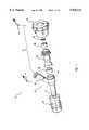
- FIG. 1is an enlarged prospective view of an adaptor having a rotatable end cap and a valve assembly in a partially disassembled condition;
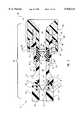
- FIG. 5is an enlarged cross-sectional view of the valve assembly of Figure 3 with an elongated instrument therethrough;
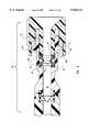
- FIG. 6is an enlarged cross-sectional view of the valve assembly of FIG. 5 showing the compressible seal in a compressed and sealed position;
- FIG. 8is an enlarged cross-sectional view of the valve assembly of FIG. 3 with another alternative embodiment of the compressible seal
- the amount of compressive force that is being exerted on the compressible sealcan be incrementally adjusted so that a seal is formed or maintained around the catheter or guidewire while still allowing the catheter or guidewire to be repositioned or even removed without having to remove substantially all of the compressive force acting on the compressible seal.
- FIG. 1depicts an adaptor 10 comprising a tubular body 12, a rotatable connector 18, and a valve assembly 20.
- Tubular body 12has a distal end 14 and an opposing proximal end 16.
- Rotatable connector 18is positioned at distal end 14 of tubular body 12.
- Rotatable connector 18provides fluid coupling between an introducer (not shown) and tubular body 12.
- Valve assembly 20is positioned at proximal end 16 of tubular body 12.
- tubular body 12includes a first supplemental access tube 22 attached thereto.
- First supplemental access tube 22has a central bore formed therethrough so as to be in fluid communication with tubular body 12.
- first supplemental access tube 22is configured to be placed in fluid communication with an elongated device. such as a catheter.
- First supplemental access tube 22can be used to introduce fluids or medical devices into the body of a patient. It can be appreciated that tubular body 12 may have various other configurations in order to carry out an intended function.
- First supplemental access tube 22is preferably positioned at an angle relative to the longitudinal axis of tubular body 12 so as to project outwardly from tubular body 12 towards proximal end 16. As shown in FIG. 1, the remote end of first supplemental access tube 22 has threads formed thereon to accommodate a conventional Luer lock attachment. Various other types of attachment structure may perform the attaching function thereof equally effectively.
- Valve assembly 20preferably includes a resilient seal 36, a compressible seal 44, and a rotatable end cap 46.
- Valve assembly 10also includes an elongated housing 42 and a slip ring 48. The configuration and interrelationships of these components are more clearly shown in FIG. 2, which depicts a partial cross-sectional exploded view of valve assembly 20.
- Tubular body 12has a longitudinal passageway or lumen 50 extending through tubular body 12.
- tubular body 12has an interior recess 52 that is axially aligned with lumen 50.
- Interior recess 52has a proximal end 54 and a distal end 56.
- the diameter of interior recess 52is defined by an interior surface 60 that extends between proximal end 54 and distal end 56 of interior recess 52.
- Lumen 50communicates at proximal end 58 thereof with distal end 56 of interior recess 52.
- Lumen 50is concentric with interior recess 52 and has an interior surface 59 with a diameter smaller than the diameter formed by interior surface 60 of interior recess 52.
- Lumen 50 and interior recess 52are preferably substantially cylindrical.
- Resilient seal 36also comprises a resilient membrane 40 that is attached to interior surface 70 of body portion 38. Resilient membrane 40 extends across the inner diameter of body portion 38. Membrane 40 is thin and relatively flexible. Membrane 40 has an aperture 78 formed therethrough.
- membrane 40is cone-shaped. Membrane 40 may have other configurations such as being semi-spherical shaped, flat, or elliptical while substantially providing the intended function thereof.
- cone-shaped membrane 40has aperture 78 formed at the apex thereof. Aperture 78 is axially aligned with lumen 50.
- An elongated instrument 250such as by way of example and not limitation, a catheter or guidewire, can be disposed through aperture 78 as depicted in FIG. 5.
- Valve assembly 20further comprises elongated housing 42 that has a longitudinal bore 86.
- housing 42has an exterior surface 80, a distal end 82, and a proximal end 84.
- Distal end 82 of housing 42has an opening 102 formed therein that is in communication with bore 86 and is configured to receive both proximal end 72 of resilient seal 36 and proximal end 16 of body 12 therein.
- Opening 102has a proximal end 104 and a distal end 106.
- An inner surface 103 of opening 102has a diameter approximately equal to the diameter of outside surface 13 of proximal end 16 of body 12.
- Bore 86communicates at a distal end 100 thereof with proximal end 104 of opening 102.
- Bore 86is concentric with opening 102 and has an interior surface 98 that has a diameter smaller than the diameter of opening 102 formed by inner surface 103.
- Opening 102is preferably cylindrical.
- Proximal end 84 of housing 42has an interior compression chamber 88 that is in communication with bore 86.
- Compression chamber 88has an interior diameter defined by an interior surface 90 which extends between a distal end 92 and a proximal end 94 thereof.
- Bore 86communicates at a proximal end 96 thereof with distal end 92 of compression chamber 88.
- Bore 86is concentric with compression chamber 88 and has a diameter formed by interior surface 98 that is smaller than the inner diameter of compression chamber 88 formed by interior surface 90.
- Bore 86 and compression chamber 88are preferably substantially cylindrical.
- Housing 42is one embodiment of structure capable of performing the function of a housing means for providing a longitudinal bore 86 therethrough in communication with lumen 50. It can be appreciated that various other embodiments of structure capable of performing the function of such housing means may be equally effective in carrying out the intended function thereof.
- Compressible seal 44has an interior surface 146 that defines a first passageway 148 therein which extends longitudinally through compressible seal 44 and is axially aligned with bore 86.
- a raised annular portionsuch as by way of example and not limitation, raised annular rib 158, is integrally formed on interior surface 146. As depicted in FIG. 2, raised annular rib 158 is semi-spherical in shape. It can be appreciated that the raised annular portion, such as raised annular rib 158, may have various other configurations and perform the functions thereof equally effectively. By way of example and not limitation, raised annular rib 158 may be shaped as half an ellipse, semi-circular, rectangular, half an octagon, or various other shapes. The function and importance of raised annular rib 158 will be discussed in further detail below.
- An annular second tongue 160projects proximally from proximal end 138 of compressible seal 44.
- Second tongue 160has a proximal end face 162.
- the inside diameter of second tongue 160defines a second recess 166 concentric with first passageway 148 of compressible seal 44 that has a diameter greater than the diameter of first passageway 148 formed by interior surface 146.
- Annular first and second tongues 150 and 160respectively, encircle the respective ends of first passageway 148.
- Compressible seal 44is one embodiment of structure capable of performing the function of a second sealing means for selectively sealing and unsealing bore 86 in response to a compressive force exerted on second sealing means.
- Second sealing meanshas a raised annular portion formed therein configured to allow an elongated instrument 250 accessing lumen 50 through passageway 148 to be repositioned or removed while still maintaining a seal capable of preventing substantially all loss of body fluids beyond the second sealing means without releasing substantially all of the compressive force acting on the second sealing means (FIG. 5).
- Other embodiments including alternative structures capable of performing the function of such a second sealing meansmay be equally effective in carrying out the intended function thereof.
- First tongue 150is configured to cooperate with third annular retaining groove 130 and first annular ridge 124 in compression chamber 88.
- First tongue 150 of compressible seal 44is received within third annular retaining groove 130 with distal end face 152 of first tongue 150 against annular end wall 122.
- First annular ridge 124is received within first recess 156 in distal end 140 of compressible seal 44.
- first tongue 150, third annular retaining groove 130, and first annular ridge 124are shown as having a rectangular-shaped cross section.
- First tongue 150, third annular retaining groove 130, and first annular ridge 124are one example of structure capable of performing the function of a first holding means for interlocking distal end 140 of compressible seal 44 within distal end 92 of compression chamber 88 such that when compressive force is exerted on compressible seal 44, distal end 140 of compressible seal 44 remains firmly in place within housing 42.
- Various other embodiments of structure capable of performing the function of such a first holding meansmay be equally effective in carrying out the intended function thereof.
- valve assembly 20includes an optional slip ring 48.
- Slip ring 48comprises a first ring 170 having an outer diameter that is substantially the same as the diameter of second recess 166 in proximal end 138 of compressible seal 44. The inner diameter of first ring 170 defines a first access 173.
- First access 173is axially aligned with first passageway 148 in compressible seal 44.
- Proximally attached to first ring 170is an annular second ring 174.
- Second ring 174has an outer diameter greater than the outer diameter of first ring 170 and an inner diameter that defines a second access 177.
- the diameter of second access 177is greater than the diameter of first access 173.
- Second access 177is concentric with first access 173 and communicates therewith.
- First ring 170is configured to be received within second recess 166 in proximal end 138 of compressible seal 44.
- Second tongue 160 of compressible seal 44encircles first ring 170 of slip ring 48 with proximal end face 162 contacting second ring 174 of slip ring 48.
- second tongue 160 and first ring 170are shown as having a substantially rectangular-shaped cross-section.
- second tongue 160 and first ring 170may be equally effective in carrying out the intended function thereof. What is important is that second tongue 160 be configured to cooperate with first ring 170 sufficiently to form a seal between proximal end 138 of compressible seal 44 and slip ring 48.
- second tongue 160 and first ring 170must cooperate sufficiently so that compressive force can be uniformly exerted upon compressible seal 44 without compressible seal 44 twisting out of position.
- slip ring 48will be discussed in greater detail below.
- Rotatable end cap 46shown in FIG. 2, is substantially cylindrical and has a proximal end 182 and an opposing distal end 184.
- End cap 46comprises an end wall 186 on proximal end 182 thereof and a side wall 188 integrally formed with end wall 186.
- a plurality of gripping ribs 190extend radially outward on the periphery of end cap 46 and are aligned with the longitudinal axis of body 12 and housing 42.
- End cap 46has an outer diameter greater than housing 42.
- Sidewall 188has an interior surface 196 that defines a recessed chamber 198 in distal end 184 of end cap 46.
- a compression ring 200extends radially inward from interior surface 196 of side wall 188 and has an inner diameter slightly smaller than the outer diameter of compression collar 118 on proximal end 84 of housing 42.
- Second engagement threads 202are configured for rotational, threaded engagement with first engagement threads 120 on proximal end 84 of housing 42.
- Rotatable end cap 46is one example of structure capable of performing the function of a compressing means for exerting compressive force on the second sealing means when the compressing means is rotated in one direction relative to the housing means and for releasing compressive force from the second sealing means when rotated in the opposite direction relative to the housing means.
- Various embodiments of structure capable of performing the function of such a compressing meansare equally effective in carrying out the intended function thereof.
- FIG. 3illustrates an assembled valve assembly 20 prior to any compressive force being exerted on compressible seal 44.
- Distal end 74 of resilient seal 36is disposed within tubular body 12.
- First annular shoulder 64is shown holding distal end 74 of resilient seal 36 in place within interior recess 52 and prevents distal end 74 from sliding into lumen 50, although cone-shaped resilient membrane 40 may partially extend into lumen 50.
- Cone-shaped membrane 40is configured to substantially block and control the loss of fluids from lumen 50 to bore 86.
- Housing 42may be attached to tubular body 12 using a conventional adhesive, although other methods of connecting housing 42 to proximal end 16 of tubular body 12 may be equally effective in carrying out the intended function thereof.
- distal end 82 of housing 42may also be connected to proximal end 16 of tubular body 12 by an interference fit or a snap fit.
- Compressible seal 44is disposed into compression chamber 88 in proximal end 84 of housing 42.
- First tongue 150 on distal end 140 of compressible seal 44is disposed in third annular retaining groove 130 (FIG. 2) in distal end 92 of compression chamber 88.
- First annular ridge 124is disposed in first recess 156 (FIG. 2) of compressible seal 44.
- First annular ridge 124prevents compressible seal 44 from moving out of position and blocking bore 86 of housing 42 as compressible seal 44 is being compressed.
- Distal end face 152 of first tongue 150contacts annular end wall 122.
- the embodiment depicted in FIG. 3includes slip ring 48 disposed in compression chamber 88 against second tongue 160 of compressible seal 44.
- First ring 170 of slip ring 48is disposed in second recess 166 (FIG. 2) of compressible seal 44 and prevents second tongue 160 from moving out of position as compressible seal 44 is compressed.
- Annular proximal end face 162 of second tongue 160 of compressible seal 44contacts and seals with second ring 174 of slip ring 48.
- slip ring 48is preferably made of a relatively rigid material having a relatively low coefficient of friction, such as polytetrafluorethylene, or more commonly known as Teflon®.
- a small quantity of oil or other lubricationsuch as medical grade silicone oil, can be used to lubricate the interactive components of valve assembly 20.
- Compressible seal 44, and more specifically interior surface 146 and raised annular rib 158,are also preferably coated with an oil. The oil prevents interior surface 146 and raised annular rib 158 from sticking together as shaft 210 is retracted from within compression chamber 88 to open first passageway 148 through compressible seal 44.
- first engagement threads 120could be positioned on interior surface 90 of compression chamber 88 while second engagement threads 202 would then be complementarily positioned on exterior surface 216 of shaft 210 for coupling and advancing shaft 210 within compression chamber 88.
- complimentary sets of barbs or ridgescould replace first engagement threads 120 and second engagement threads 202. As shaft 210 is advanced within compression chamber 88, the complimentary sets of barbs or ridges can mechanically interact to couple shaft 210 to housing 42.
- first passageway 148 within compressible seal 44end cap 46 is rotated relative to housing 42, causing shaft 210 to advance within compression chamber 88 (see FIG. 2) as discussed above.
- compressible seal 44is compressed which causes raised annular rib 158 and interior surface 146 of compressible seal 44 to project radially inward, thereby tending to constrict first passageway 148 (FIG. 2) within compressible seal 44.
- compressible seal 44compresses radially outwardly against interior surface 90 of compression chamber 88 (FIG. 2) so as to form a seal therebetween.
- Shaft 210can continue to be advanced until raised annular rib 158 is pressed together against itself to completely close and seal passageway 148 through compressible seal 44.
- an elongated member 250may be longitudinally disposed through passageway 148 of compressible seal 44 and aperture 78 of cone-shaped membrane 40 in resilient seal 36 for insertion into the cardiovascular system of a patient.
- FIG. 5depicts adaptor 10 with elongated member 250 disposed therein prior to compressing compressible seal 44 thereagainst by rotating end cap 46 to advance shaft 210.
- cone-shaped resilient membrane 40With elongated instrument 250 disposed in resilient seal 36, cone-shaped resilient membrane 40 substantially forms a seal around elongated member 250.
- Cone-shaped membrane 40is configured to substantially stop the loss of any fluids beyond interior recess 52 (FIG. 2) of body 12. It is possible, however, that in some instances some amount of body fluids that may pass through aperture 78 of membrane 40 into bore 86 of housing 42.
- compressible seal 44is configured to prevent the passage of any fluids that may pass beyond membrane 40.
- Compressible seal 44is designed to form a seal around elongated instrument 250 and for selectively opening and closing longitudinal bore 86 in housing 42 in response to a compressive force exerted thereon.
- Raised annular rib 158is configured to allow elongated instrument 250 to be repositioned or removed while still maintaining a seal capable of substantially preventing the passage of body fluids beyond compressible seal 44 without having to release substantially all of the compressive forces acting on compressible seal 44.
- gap 240is sufficiently small such that even when compressible seal 44 is substantially uncompressed, raised annular rib 158 will be able to block the majority of fluids that may have passed beyond resilient seal 36 into bore 86.
- end cap 46may be rotated slightly to cause shaft 210 to exert a compressive force on slip ring 48, which in turn transfers the compressive force to compressible seal 44.
- the compressive forcecauses raised annular rib 158 and interior surface 146 of compressible seal 44 to move radially inward in an amount sufficient to close gap 240 and to form a seal about elongated instrument 250.
- raised annular rib 158will exert very little radial force against elongated instrument 250 while nevertheless maintaining an adequate seal. This allows for longitudinal adjustments or removal of elongated instrument 250 to be made without the user having rotate end cap 46 to release all the compressive force acting on compressible seal 44 every time elongated instrument 250 is to be moved.
- Raised annular rib 158 of compressible seal 44is configured to incrementally adjust the tightness of the seal around elongated instrument 250 in precise increments when end cap 46 is rotated.
- the user of valve assembly 20is able to selectively advance rotatable end cap 46 to precisely adjust the tightness of the seal formed around elongated instrument 250 as desired.
- the tightness of the seal around elongated instrument 250is directly related to the amount of force exerted by raised annular rib 158 on elongated member 250. This provides a "sealing window" where compressible seal 44 remains scaled around elongated instrument 250 in varying amounts by exerting varying amounts of force on elongated instrument 250 while still allowing elongated instrument 250 to be repositioned or even removed.
- the user of adaptor 10can minimize the drag acting on elongated instrument 250 if desired when repositioning or moving elongated instruments 250 while still maintaining an adequate seal about elongated instrument 250.
- elongated member 250can be repositioned or even removed while maintaining a seal sufficient to substantially minimize the loss of body fluid from valve assembly 20.
- FIG. 7illustrates an alternative embodiment of valve assembly 268 employing an alternate compressible seal 260 in place of compressible seal 44.
- Alternate compressible seal 260comprises a generally elongated cylindrical body portion 38 that has an exterior surface 136 and an interior surface 146 extending between a proximal end 138 and a distal end 140.
- Alternate compressible seal 260also comprises a raised annular portion such as, by way of example and not by limitation, an annular fin 262 that is integrally formed on interior surface 146 and extends into first passageway 148.
- Alternate compressible seal 260is compressed in the same manner as compressible seal 44 illustrated in FIGS. 1-6 causing annular fin 262 and interior surface 146 to move radially inward to form a seal in response to the compressive force exerted by rotating end cap 46.
- valve assembly 268does not include optional slip ring 48
- shaft 210 of rotatable end cap 46cooperates directly with proximal end 138 of alternate compressible seal 270.
- second annular ridge 224 on distal end 212 of shaft 210is disposed within second recess 166 (FIG. 2) in proximal end 138 of alternate compressible seal 270.
- annular second tongue 160 that projects proximally from proximal end 138 of compressible seal 270is disposed in fourth annular retaining groove 230 (FIG. 2).
- Proximal end face 162 of second tongue 160contacts distal end 212 of shaft 210.
- center peak 272moves radially inward to form a seal either against itself or about elongated instrument 250 when elongated instrument 250 is inserted through first passageway 148.
- Second supplemental access tube 24includes a peripheral valve assembly 302 that is similar to a portion of valve assembly 20.
- Peripheral valve assembly 302includes a housing 304, a compressible seal 44', a rotatable end cap 46', and an optional slip ring 48'.
- Housing 304is substantially the same as the proximal end 84 of housing 42 shown in FIGS. 1 and 2.
- Compressible seal 44', optional slip ring 48', and rotatable end cap 46'are preferably similar to those various embodiments shown and discussed relative to FIGS. 1-8.
- FIG. 10illustrates an alternate embodiment of adaptor 298 depicted in FIG. 9.
- Adaptor 310 depicted in FIG. 10includes an alternative valve assembly 312 in place of valve assembly 20.
- alternative valve assembly 312comprises a resilient seal 36, a housing 42, a compressible seal 44, and a slip ring 48, as were previously discussed in various forms relative to FIGS. 1-9.
- valve assembly 312comprises a second compressible seal 3 14 and a washer 316.
- Compressible seal 44is configured to cooperate with washer 316 and second compressible seal 314.
- second recess 166 in proximal end 138 (FIG. 2) of compressible seal 44may be elongated or deepened longitudinally to better receive and accommodate both of washer 316 and second compressible seal 314 therein as discussed more fully below.
- both main portion 330 and shoulder portion 332 of second compressible seal 314are substantially cylindrical in shape. It can be appreciated that main portion 330 of second compressible seal 314 may have other configurations as long as second compressible seal 314 and second recess 166 (FIG. 2) in proximal end 138 of compressible seal 44 are configured to cooperate.
- Shoulder portion 332is configured to cooperate with both compression chamber 88 (FIG. 2) of housing 42 and first ring 170 (FIG. 2) of slip ring 48 or shaft 210 (FIG. 2), depending on the embodiment.
- the outside diameter of shoulder portion 332 of second compressible seal 314is substantially equal to the inner diameter of compression chamber 88, thereby allowing compressible seal 44, washer 316, second compressible seal 314, and optional slip ring 48 to all be disposed within compression chamber 88.
- the inner diameter of shoulder portion 332is substantially the same as the outside diameter of first ring 170 (FIG. 2) of slip ring 48 and is configured to receive first ring 170 therein. If slip ring 48 is not used, the inner diameter of shoulder portion 332 should be substantially equal to the outside diameter of annular second ridge 224 on distal end 212 of shaft 210 (FIG. 2).
- shoulder portion 332 of second compressible seal 314forms a third recess 336 capable of retaining first ring 170 therein.
- Main portion 330has an interior surface that defines a passageway (not shown) that extends longitudinally therethrough and is axially aligned with opening 322 in washer 316 and passageway 148 (FIG. 2) in compressible seal 44.
- the passageway of main portion 330 of second compressible seal 314has a diameter smaller than the diameter of third recess 336 formed in shoulder portion 332.
- a support surface (not shown)extends from the diameter of third recess 336 to the passageway (not shown). It can be appreciated that various other configurations of shoulder portion 332, compression chamber 88, and slip ring 48 may be utilized that are equally effective in carrying out the intended function thereof.
- compressible seal 44 and second compressible seal 314comprise different elastomeric materials or silicon rubber having different durometer readings.
- compressible seal 44comprise a material that is harder than the material comprising second compressible seal 314.
- second compressible seal 314comprises a material that is softer than the material comprising compressible seal 44
- second compressible seal 314will form a seal prior to compressible seal 44.
- second compressible seal 314will compress radially inward further than compressible seal 44 and thereby exert a greater sealing force on elongated instrument 250 when the same force is applied to both compressible seal 44 and second compressible 314.
- Second compressible seal 314is one example of structure capable of performing the function of a third sealing means for progressively opening and closing longitudinal bore 86 and housing 42 in combination with second sealing means.
- Valve assembly 20can be used for various functions. In one position, valve assembly 20 can be used to completely block off proximal end 16 of tubular body 12 so as to prevent the escape of blood or other bodily fluids flowing from a patient into adaptor 10. Alternatively, valve assembly 20 can be used to form a seal around a medical instrument such as elongated instrument 250 when the instrument is received within valve assembly 20 past tubular body 18 and into the cardiovascular system of a patient. Valve assembly 20 also prevents the back flow of bodily fluids from leaking out of adaptor 10 when an elongated member is removed from valve assembly 20. Valve assembly 20 is also configured to allow a user to selectively adjust the amount of compression acting upon compressible seal 44 by means of rotatable end cap 46.
- valve assembly 10is capable of forming an adequate seal around elongated instrument 250 while minimizing the drag in order to allow elongated instrument 250 to be repositioned or removed without having to rotate end cap 46 each time.
Landscapes
- Health & Medical Sciences (AREA)
- Heart & Thoracic Surgery (AREA)
- Pulmonology (AREA)
- Engineering & Computer Science (AREA)
- Anesthesiology (AREA)
- Biomedical Technology (AREA)
- Hematology (AREA)
- Life Sciences & Earth Sciences (AREA)
- Animal Behavior & Ethology (AREA)
- General Health & Medical Sciences (AREA)
- Public Health (AREA)
- Veterinary Medicine (AREA)
- Media Introduction/Drainage Providing Device (AREA)
- Infusion, Injection, And Reservoir Apparatuses (AREA)
Abstract
Description
Claims (26)
Priority Applications (1)
| Application Number | Priority Date | Filing Date | Title |
|---|---|---|---|
| US08/950,627US5935112A (en) | 1997-10-15 | 1997-10-15 | Hemostasis valve with catheter/guidewire seals |
Applications Claiming Priority (1)
| Application Number | Priority Date | Filing Date | Title |
|---|---|---|---|
| US08/950,627US5935112A (en) | 1997-10-15 | 1997-10-15 | Hemostasis valve with catheter/guidewire seals |
Publications (1)
| Publication Number | Publication Date |
|---|---|
| US5935112Atrue US5935112A (en) | 1999-08-10 |
Family
ID=25490688
Family Applications (1)
| Application Number | Title | Priority Date | Filing Date |
|---|---|---|---|
| US08/950,627Expired - LifetimeUS5935112A (en) | 1997-10-15 | 1997-10-15 | Hemostasis valve with catheter/guidewire seals |
Country Status (1)
| Country | Link |
|---|---|
| US (1) | US5935112A (en) |
Cited By (157)
| Publication number | Priority date | Publication date | Assignee | Title |
|---|---|---|---|---|
| US6287280B1 (en)* | 1999-09-07 | 2001-09-11 | Merit Medical Systems, Inc. | Hemostasis valve apparatus with integral introducer |
| US6301752B1 (en)* | 1999-12-30 | 2001-10-16 | Scott Koppang | Cord organizer |
| US6572590B1 (en)* | 2000-07-13 | 2003-06-03 | Merit Medical Systems, Inc. | Adjustable quick-release valve with toggle capability |
| US20030127620A1 (en)* | 2002-01-09 | 2003-07-10 | Eric Houde | Fluid management valve |
| JP2003525660A (en)* | 1999-09-07 | 2003-09-02 | メリット・メディカル・システムズ・インコーポレーテッド | Hemostasis valve device with integral introducer |
| US6688306B1 (en)* | 2000-11-27 | 2004-02-10 | Kimberly-Clark Worldwide, Inc. | Clamping assembly for maintaining the position of a respiratory care treatment device |
| US6695820B1 (en)* | 1999-03-11 | 2004-02-24 | Advanced Cardiovascular Systems, Inc. | Bleed back control assembly |
| US6712791B2 (en) | 1999-12-30 | 2004-03-30 | Cook Vascular Incorporated | Splittable medical valve |
| WO2004030737A1 (en)* | 2002-09-30 | 2004-04-15 | Arrow Japan, Ltd. | Tube assembly for use in bile drainage after biliary surgery |
| US6723073B2 (en) | 2002-09-06 | 2004-04-20 | Cardiac Pacemakers, Inc. | Hemostasis valve for use with a left ventricular pacing lead |
| US6755806B1 (en)* | 1997-05-31 | 2004-06-29 | Von Casimir Wolf | Catheter insertion device with a system for liquid-tight clamping of the insertion lumen |
| US20040172008A1 (en)* | 2002-11-19 | 2004-09-02 | Gmp/Cardiac Care, Inc. | Hemostasis valve and method of using a hemostasis valve |
| US20040178586A1 (en)* | 2003-02-20 | 2004-09-16 | Biotronik Gmbh & Co. Kg | Sealing element |
| US20050033239A1 (en)* | 2003-08-06 | 2005-02-10 | Trivascular, Inc. | Passive hemostatic sheath valve |
| US20050113757A1 (en)* | 2003-08-08 | 2005-05-26 | Mcfarlane Richard H. | Seal positioning assembly |
| US20050171479A1 (en)* | 2003-12-11 | 2005-08-04 | Hruska Christopher L. | Hemostatic valve assembly |
| US20050235996A1 (en)* | 2004-04-27 | 2005-10-27 | Hooser David Theron V | Clamping assembly for limiting the depth of insertion of a respiratory care treatment device |
| US7094218B2 (en) | 2004-03-18 | 2006-08-22 | C. R. Bard, Inc. | Valved catheter |
| US20060220325A1 (en)* | 2002-04-26 | 2006-10-05 | Mcfarlane Richard H | Floating seal assembly for a trocar |
| US20070010796A1 (en)* | 2005-06-23 | 2007-01-11 | Derek Moran | Catheter device |
| US20070100295A1 (en)* | 2005-10-11 | 2007-05-03 | Belley Richard A | IV catheter with in-line valve and methods related thereto |
| US20070276434A1 (en)* | 2004-01-23 | 2007-11-29 | Js Vascular, Inc. | Vascular sheath |
| US7326188B1 (en) | 2002-08-02 | 2008-02-05 | Elcam Medical | Anesthesia manifold and induction valve |
| EP1501570A4 (en)* | 2002-04-26 | 2008-03-12 | Taut Inc | Floating seal assembly for a trocar |
| US20080108976A1 (en)* | 2006-11-08 | 2008-05-08 | Cardiac Pacemakers, Inc. | Break-away hemostasis hub |
| US20080262465A1 (en)* | 2005-10-30 | 2008-10-23 | Medimop Medical Projects Ltd. | Needleless additive control valve |
| US20080275397A1 (en)* | 2004-08-31 | 2008-11-06 | Bonnette Michael J | Low pierce force needle port |
| US20090069757A1 (en)* | 2007-09-08 | 2009-03-12 | Medco International, Llc | Elastomeric seal for use within a catheter component |
| US20090118575A1 (en)* | 2007-11-06 | 2009-05-07 | Olympus Medical Systems Corp. | Endoscopic system, treatment section operation check instrument for the same, and treatment section operation check method |
| US7578803B2 (en) | 2004-03-18 | 2009-08-25 | C. R. Bard, Inc. | Multifunction adaptor for an open-ended catheter |
| US7637893B2 (en) | 2004-04-30 | 2009-12-29 | C. R. Bard, Inc. | Valved sheath introducer for venous cannulation |
| US20100036329A1 (en)* | 2008-08-07 | 2010-02-11 | Nasser Razack | Hemostasis valve |
| JP2010512206A (en)* | 2006-12-13 | 2010-04-22 | アーツナイミッテル・ゲーエムベーハー・アポテーカー・フェッター・ウント・コンパニー・ラフェンスブルク | Fitting for syringe or cartridge |
| US7731694B2 (en) | 2005-10-24 | 2010-06-08 | Cardiac Pacemakers, Inc. | Hemostasis seal |
| US7854731B2 (en) | 2004-03-18 | 2010-12-21 | C. R. Bard, Inc. | Valved catheter |
| US7875019B2 (en) | 2005-06-20 | 2011-01-25 | C. R. Bard, Inc. | Connection system for multi-lumen catheter |
| US7883502B2 (en) | 2004-03-18 | 2011-02-08 | C. R. Bard, Inc. | Connector system for a proximally trimmable catheter |
| US20110054405A1 (en)* | 2009-09-01 | 2011-03-03 | Pacesetter, Inc. | Hemostasis valve with iris seal |
| USD634007S1 (en) | 2009-03-31 | 2011-03-08 | Medimop Medical Projects Ltd. | Needleless additive control valve |
| US20110137120A1 (en)* | 2004-01-30 | 2011-06-09 | Fujifilm Corporation | Endoscope apparatus |
| US8083728B2 (en)* | 2004-03-18 | 2011-12-27 | C. R. Bard, Inc. | Multifunction adaptor for an open-ended catheter |
| EP2402052A1 (en)* | 2005-06-02 | 2012-01-04 | Olympus Corporation | Balloon catheter |
| US8177770B2 (en) | 2004-04-01 | 2012-05-15 | C. R. Bard, Inc. | Catheter connector system |
| US8177771B2 (en) | 2004-03-18 | 2012-05-15 | C. R. Bard, Inc. | Catheter connector |
| US20120221024A1 (en)* | 2011-02-28 | 2012-08-30 | Normedix Llc | Hemostasis sealing device |
| US8337484B2 (en) | 2009-06-26 | 2012-12-25 | C. R. Band, Inc. | Proximally trimmable catheter including pre-attached bifurcation and related methods |
| US8403890B2 (en) | 2004-11-29 | 2013-03-26 | C. R. Bard, Inc. | Reduced friction catheter introducer and method of manufacturing and using the same |
| US20130116724A1 (en)* | 2011-11-08 | 2013-05-09 | Boston Scientific Scimed, Inc. | Handle assembly for a left atrial appendage occlusion device |
| US8608702B2 (en) | 2007-10-19 | 2013-12-17 | C. R. Bard, Inc. | Introducer including shaped distal region |
| US8684994B2 (en) | 2010-02-24 | 2014-04-01 | Medimop Medical Projects Ltd. | Fluid transfer assembly with venting arrangement |
| US8752598B2 (en) | 2011-04-17 | 2014-06-17 | Medimop Medical Projects Ltd. | Liquid drug transfer assembly |
| US8753325B2 (en) | 2010-02-24 | 2014-06-17 | Medimop Medical Projects, Ltd. | Liquid drug transfer device with vented vial adapter |
| US20140187866A1 (en)* | 2010-09-17 | 2014-07-03 | United States Endoscopy Group, Inc. | Biopsy inlet valve |
| US8852145B2 (en) | 2010-11-14 | 2014-10-07 | Medimop Medical Projects, Ltd. | Inline liquid drug medical device having rotary flow control member |
| US8905994B1 (en) | 2011-10-11 | 2014-12-09 | Medimop Medical Projects, Ltd. | Valve assembly for use with liquid container and drug vial |
| WO2014198828A1 (en)* | 2013-06-12 | 2014-12-18 | W.O.M. World Of Medicine Ag | Connecting element and connecting assembly |
| USD720451S1 (en) | 2012-02-13 | 2014-12-30 | Medimop Medical Projects Ltd. | Liquid drug transfer assembly |
| US8926564B2 (en) | 2004-11-29 | 2015-01-06 | C. R. Bard, Inc. | Catheter introducer including a valve and valve actuator |
| US8932260B2 (en) | 2004-11-29 | 2015-01-13 | C. R. Bard, Inc. | Reduced-friction catheter introducer and method of manufacturing and using the same |
| US8979792B2 (en) | 2009-11-12 | 2015-03-17 | Medimop Medical Projects Ltd. | Inline liquid drug medical devices with linear displaceable sliding flow control member |
| US8998875B2 (en) | 2009-10-01 | 2015-04-07 | Medimop Medical Projects Ltd. | Vial assemblage with vial and pre-attached fluid transfer device |
| USD734868S1 (en) | 2012-11-27 | 2015-07-21 | Medimop Medical Projects Ltd. | Drug vial adapter with downwardly depending stopper |
| USD737436S1 (en) | 2012-02-13 | 2015-08-25 | Medimop Medical Projects Ltd. | Liquid drug reconstitution assembly |
| US9283324B2 (en) | 2012-04-05 | 2016-03-15 | Medimop Medical Projects, Ltd | Fluid transfer devices having cartridge port with cartridge ejection arrangement |
| US9339438B2 (en) | 2012-09-13 | 2016-05-17 | Medimop Medical Projects Ltd. | Telescopic female drug vial adapter |
| USD757933S1 (en) | 2014-09-11 | 2016-05-31 | Medimop Medical Projects Ltd. | Dual vial adapter assemblage |
| USD765837S1 (en) | 2013-08-07 | 2016-09-06 | Medimop Medical Projects Ltd. | Liquid transfer device with integral vial adapter |
| US20160262767A1 (en)* | 2009-06-17 | 2016-09-15 | Coherex Medical, Inc. | Medical device and delivery system for modification of left atrial appendage and methods thereof |
| USD767124S1 (en) | 2013-08-07 | 2016-09-20 | Medimop Medical Projects Ltd. | Liquid transfer device with integral vial adapter |
| CN105962990A (en)* | 2016-06-08 | 2016-09-28 | 深圳市科奕顿生物医疗科技有限公司 | An interventional medical device delivery system |
| US9597483B2 (en) | 2004-11-29 | 2017-03-21 | C. R. Bard, Inc. | Reduced-friction catheter introducer and method of manufacturing and using the same |
| WO2017049073A1 (en)* | 2015-09-18 | 2017-03-23 | Merit Medical Systems, Inc. | Hemostasis valves and related components and methods |
| EP3058894B1 (en) | 2005-09-13 | 2017-07-26 | Boston Scientific Scimed, Inc. | Two-part package for medical implant |
| US9795536B2 (en) | 2012-08-26 | 2017-10-24 | Medimop Medical Projects, Ltd. | Liquid drug transfer devices employing manual rotation for dual flow communication step actuations |
| US9801786B2 (en) | 2013-04-14 | 2017-10-31 | Medimop Medical Projects Ltd. | Drug container closure for mounting on open-topped drug container to form drug reconstitution assemblage for use with needleless syringe |
| USD801522S1 (en) | 2015-11-09 | 2017-10-31 | Medimop Medical Projects Ltd. | Fluid transfer assembly |
| AU2016202012B2 (en)* | 2015-04-23 | 2017-12-07 | Freudenberg Medical, Llc | An automatic medical valve with a variable diameter seal |
| US9839580B2 (en) | 2012-08-26 | 2017-12-12 | Medimop Medical Projects, Ltd. | Liquid drug transfer devices |
| US9884175B2 (en)* | 2015-04-23 | 2018-02-06 | Freudenberg Medical, Llc | Automatic medical valve with a variable diameter seal |
| US9943463B2 (en) | 2013-05-10 | 2018-04-17 | West Pharma. Services IL, Ltd. | Medical devices including vial adapter with inline dry drug module |
| US10064628B2 (en) | 2009-06-17 | 2018-09-04 | Coherex Medical, Inc. | Medical device for modification of left atrial appendage and related systems and methods |
| US10076337B2 (en) | 2009-06-17 | 2018-09-18 | Coherex Medical, Inc. | Medical device for modification of left atrial appendage and related systems and methods |
| WO2018169685A1 (en)* | 2017-03-13 | 2018-09-20 | Boston Scientific Scimed, Inc. | Hemostasis valves and methods for making and using hemostasis valves |
| USD832430S1 (en) | 2016-11-15 | 2018-10-30 | West Pharma. Services IL, Ltd. | Dual vial adapter assemblage |
| US10278897B2 (en) | 2015-11-25 | 2019-05-07 | West Pharma. Services IL, Ltd. | Dual vial adapter assemblage including drug vial adapter with self-sealing access valve |
| US10285907B2 (en) | 2015-01-05 | 2019-05-14 | West Pharma. Services IL, Ltd. | Dual vial adapter assemblages with quick release drug vial adapter for ensuring correct usage |
| WO2019108813A1 (en)* | 2017-12-01 | 2019-06-06 | Merit Medical Systems, Inc. | Hemostasis valve systems and associated methods |
| US10357429B2 (en) | 2015-07-16 | 2019-07-23 | West Pharma. Services IL, Ltd. | Liquid drug transfer devices for secure telescopic snap fit on injection vials |
| US10391292B2 (en) | 2016-06-15 | 2019-08-27 | Surmodics, Inc. | Hemostasis sealing device with constriction ring |
| US20190262598A1 (en)* | 2018-02-28 | 2019-08-29 | Stryker Corporation | Hemostasis valve allowing for lateral translation and simultaneous aspiration |
| US10420564B2 (en) | 2009-01-08 | 2019-09-24 | Coherex Medical, Inc. | Medical device for modification of left atrial appendage and related systems and methods |
| US20190380742A1 (en)* | 2018-06-15 | 2019-12-19 | Ethicon Llc | Asymmetric shaft seal |
| US10537332B2 (en) | 2009-06-17 | 2020-01-21 | Coherex Medical, Inc. | Medical device for modification of left atrial appendage and related systems and methods |
| US10557552B2 (en) | 2016-11-21 | 2020-02-11 | Cardiac Pacemakers, Inc. | Trough seal |
| US10582930B2 (en) | 2009-06-17 | 2020-03-10 | Coherex Medical, Inc. | Medical device for modification of left atrial appendage and related systems and methods |
| US10631969B2 (en) | 2009-06-17 | 2020-04-28 | Coherex Medical, Inc. | Medical device for modification of left atrial appendage and related systems and methods |
| US10646404B2 (en) | 2016-05-24 | 2020-05-12 | West Pharma. Services IL, Ltd. | Dual vial adapter assemblages including identical twin vial adapters |
| US10688295B2 (en) | 2013-08-07 | 2020-06-23 | West Pharma. Services IL, Ltd. | Liquid transfer devices for use with infusion liquid containers |
| US10737086B2 (en) | 2017-03-13 | 2020-08-11 | Boston Scientific Limited | Hemostasis valves and methods for making and using hemostasis valves |
| US10758719B2 (en) | 2016-12-15 | 2020-09-01 | Surmodics, Inc. | Low-friction sealing devices |
| US10765604B2 (en) | 2016-05-24 | 2020-09-08 | West Pharma. Services IL, Ltd. | Drug vial adapter assemblages including vented drug vial adapter and vented liquid vial adapter |
| US10772797B2 (en) | 2016-12-06 | 2020-09-15 | West Pharma. Services IL, Ltd. | Liquid drug transfer devices for use with intact discrete injection vial release tool |
| US10806667B2 (en) | 2016-06-06 | 2020-10-20 | West Pharma. Services IL, Ltd. | Fluid transfer devices for filling drug pump cartridges with liquid drug contents |
| US10806671B2 (en) | 2016-08-21 | 2020-10-20 | West Pharma. Services IL, Ltd. | Syringe assembly |
| US10835729B2 (en) | 2016-11-09 | 2020-11-17 | Boston Scientific Limited | Hemostasis valve design for introducer sheath |
| USD903864S1 (en) | 2018-06-20 | 2020-12-01 | West Pharma. Services IL, Ltd. | Medication mixing apparatus |
| US10945921B2 (en) | 2017-03-29 | 2021-03-16 | West Pharma. Services IL, Ltd. | User actuated liquid drug transfer devices for use in ready-to-use (RTU) liquid drug transfer assemblages |
| US10953214B2 (en) | 2017-09-12 | 2021-03-23 | Boston Scientific Limited | Hemostasis valves and methods for making and using hemostasis valves |
| US10960501B2 (en) | 2017-03-13 | 2021-03-30 | Boston Scientific Limited | Hemostasis valves and methods for making and using hemostasis valves |
| USD917693S1 (en) | 2018-07-06 | 2021-04-27 | West Pharma. Services IL, Ltd. | Medication mixing apparatus |
| US11027062B2 (en) | 2017-12-03 | 2021-06-08 | West Pharma. Services IL, Ltd. | Liquid transfer device with telescopic vial adapter for use with infusion liquid container and discrete injection vial |
| USD923812S1 (en) | 2019-01-16 | 2021-06-29 | West Pharma. Services IL, Ltd. | Medication mixing apparatus |
| USD923782S1 (en) | 2019-01-17 | 2021-06-29 | West Pharma. Services IL, Ltd. | Medication mixing apparatus |
| US11154303B2 (en) | 2007-10-19 | 2021-10-26 | Coherex Medical, Inc. | Medical device for modification of left atrial appendage and related systems and methods |
| US11207497B1 (en) | 2020-08-11 | 2021-12-28 | Imperative Care, Inc. | Catheter with enhanced tensile strength |
| US11207512B2 (en) | 2015-04-23 | 2021-12-28 | Freudenberg Medical, Llc | Automatic medical valve with a variable diameter seal |
| US11224434B2 (en) | 2017-01-06 | 2022-01-18 | Incept, Llc | Thromboresistant coatings for aneurysm treatment devices |
| US11253277B2 (en) | 2019-12-18 | 2022-02-22 | Imperative Care, Inc. | Systems for accessing a central pulmonary artery |
| US20220062594A1 (en)* | 2011-12-22 | 2022-03-03 | Ecp Entwicklungsgesellschaft Mbh | Sheath device for inserting a catheter |
| US11291821B2 (en) | 2017-03-13 | 2022-04-05 | Boston Scientific Limited | Hemostasis valves and methods for making and using hemostasis valves |
| US11311303B2 (en) | 2018-05-01 | 2022-04-26 | Incept, Llc | Enhanced flexibility neurovascular catheter with tensile support |
| USD954253S1 (en) | 2019-04-30 | 2022-06-07 | West Pharma. Services IL, Ltd. | Liquid transfer device |
| US11369355B2 (en) | 2019-06-17 | 2022-06-28 | Coherex Medical, Inc. | Medical device and system for occluding a tissue opening and method thereof |
| USD956958S1 (en) | 2020-07-13 | 2022-07-05 | West Pharma. Services IL, Ltd. | Liquid transfer device |
| US11395665B2 (en) | 2018-05-01 | 2022-07-26 | Incept, Llc | Devices and methods for removing obstructive material, from an intravascular site |
| WO2022159308A1 (en) | 2021-01-19 | 2022-07-28 | Silara Medtech Inc. | Hemostasis valve, introducer and retrieval device |
| US11439799B2 (en) | 2019-12-18 | 2022-09-13 | Imperative Care, Inc. | Split dilator aspiration system |
| US11471647B2 (en) | 2014-11-07 | 2022-10-18 | C. R. Bard, Inc. | Connection system for tunneled catheters |
| US11471582B2 (en)* | 2018-07-06 | 2022-10-18 | Incept, Llc | Vacuum transfer tool for extendable catheter |
| US11504020B2 (en) | 2019-10-15 | 2022-11-22 | Imperative Care, Inc. | Systems and methods for multivariate stroke detection |
| US11517335B2 (en) | 2018-07-06 | 2022-12-06 | Incept, Llc | Sealed neurovascular extendable catheter |
| US11553935B2 (en) | 2019-12-18 | 2023-01-17 | Imperative Care, Inc. | Sterile field clot capture module for use in thrombectomy system |
| US11565082B2 (en) | 2020-03-10 | 2023-01-31 | Imperative Care, Inc. | Enhanced flexibility neurovascular catheter |
| CN116020047A (en)* | 2021-10-25 | 2023-04-28 | 杭州德晋医疗科技有限公司 | hemostasis valve |
| US11642285B2 (en) | 2017-09-29 | 2023-05-09 | West Pharma. Services IL, Ltd. | Dual vial adapter assemblages including twin vented female vial adapters |
| US11672661B2 (en) | 2019-08-22 | 2023-06-13 | Silara Medtech Inc. | Annuloplasty systems and methods |
| WO2023164139A1 (en)* | 2022-02-25 | 2023-08-31 | Boston Scientific Medical Device Limited | Dual arm hemostasis valve hub for sheaths |
| US20230293389A1 (en)* | 2017-05-17 | 2023-09-21 | Klim-Loc, Llc | Devices and methods for needleless extraction and administration of contents from vials |
| US11766539B2 (en) | 2019-03-29 | 2023-09-26 | Incept, Llc | Enhanced flexibility neurovascular catheter |
| CN116983534A (en)* | 2023-09-27 | 2023-11-03 | 山东百多安医疗器械股份有限公司 | High-pressure-resistant auxiliary device of silicone rubber catheter |
| US11812969B2 (en) | 2020-12-03 | 2023-11-14 | Coherex Medical, Inc. | Medical device and system for occluding a tissue opening and method thereof |
| WO2024030780A1 (en)* | 2022-08-01 | 2024-02-08 | Terumo Corporation | Hemostasis valve |
| US11896782B2 (en) | 2017-08-23 | 2024-02-13 | C. R. Bard, Inc. | Priming and tunneling system for a retrograde catheter assembly |
| WO2024043892A1 (en)* | 2022-08-25 | 2024-02-29 | Bard Peripheral Vascular, Inc. | An introducer with lubricating cap |
| US11918542B2 (en) | 2019-01-31 | 2024-03-05 | West Pharma. Services IL, Ltd. | Liquid transfer device |
| WO2024108124A3 (en)* | 2022-11-17 | 2024-06-27 | Microvention, Inc. | Self-healing seal and connector port |
| WO2024238254A1 (en)* | 2023-05-12 | 2024-11-21 | Boston Scientific Medical Device Limited | Introducer sheath with dual arm hub having inbuilt tightening port |
| US12171917B1 (en) | 2024-01-08 | 2024-12-24 | Imperative Care, Inc. | Devices for blood capture and reintroduction during aspiration procedure |
| US12201506B2 (en) | 2019-12-18 | 2025-01-21 | Imperative Care, Inc. | Rotatable thrombus engagement tool |
| WO2025034801A1 (en)* | 2023-08-08 | 2025-02-13 | Boston Scientific Medical Device Limited | Introducer sheath with dual arm hub having encased tightening port mechanism |
| US12232838B2 (en) | 2021-08-12 | 2025-02-25 | Imperative Care, Inc. | Method of robotically performing a neurovascular procedure |
| CN119587866A (en)* | 2023-09-08 | 2025-03-11 | 北京先瑞达医疗科技有限公司 | A hemostatic valve |
| US12274670B2 (en) | 2019-04-09 | 2025-04-15 | West Pharma. Services IL, Ltd. | Liquid transfer device with integrated syringe |
| USD1077996S1 (en) | 2021-10-18 | 2025-06-03 | Imperative Care, Inc. | Inline fluid filter |
| US12343479B2 (en) | 2016-02-24 | 2025-07-01 | Incept, Llc | Neurovascular catheter |
| EP4578482A1 (en)* | 2023-12-27 | 2025-07-02 | Biosense Webster (Israel) Ltd. | Insertion tool for catheter devices |
| US12427091B2 (en) | 2019-01-18 | 2025-09-30 | West Pharma. Services IL, Ltd. | Liquid transfer devices for use with intravenous (IV) bottles |
Citations (17)
| Publication number | Priority date | Publication date | Assignee | Title |
|---|---|---|---|---|
| US4723550A (en)* | 1986-11-10 | 1988-02-09 | Cordis Corporation | Leakproof hemostasis valve with single valve member |
| US4857062A (en)* | 1988-03-09 | 1989-08-15 | Medical Parameters, Inc. | Catheter introducer valve |
| US4978341A (en)* | 1988-04-07 | 1990-12-18 | Schneider Europe | Introducer valve for a catheter arrangement |
| US5009391A (en)* | 1988-05-02 | 1991-04-23 | The Kendall Company | Valve assembly |
| US5059186A (en)* | 1988-03-07 | 1991-10-22 | Vitaphore Corporation | Percutaneous access device |
| US5195980A (en)* | 1992-01-03 | 1993-03-23 | Thomas Medical Products, Inc. | Hemostatic valve |
| US5269764A (en)* | 1992-08-21 | 1993-12-14 | Devices For Vascular Intervention, Inc. | Hemostatic gasket and valve assembly |
| US5324271A (en)* | 1993-06-04 | 1994-06-28 | Cordis Corporation | Double seal hemostasis connector |
| US5338314A (en)* | 1991-04-22 | 1994-08-16 | B. Braun Medical, Inc. | Rotating Y-connector |
| US5338313A (en)* | 1992-12-17 | 1994-08-16 | Thomas J. Fogarty, M.D. | Adjustable valve having a radially compressible sealing body |
| US5350364A (en)* | 1991-10-18 | 1994-09-27 | Ethicon, Inc. | Universal seal for trocar assembly |
| US5352215A (en)* | 1992-08-26 | 1994-10-04 | Scimed Life Systems, Inc. | Y-adapter with a sideport radius |
| US5507732A (en)* | 1994-10-05 | 1996-04-16 | Medtronic, Inc. | Quick assembly catheter manifold |
| US5591137A (en)* | 1995-07-14 | 1997-01-07 | Merit Medical Systems, Inc. | Hemostasis valve with locking seal |
| US5599327A (en)* | 1993-12-16 | 1997-02-04 | Terumo Kabushiki Kaisha | Connector |
| US5693025A (en)* | 1995-07-14 | 1997-12-02 | Merit Medical Systems, Inc. | Adapter with hemostasis valve and rotatable connector |
| US5700251A (en)* | 1994-12-02 | 1997-12-23 | Nissho Corporation | Epidural catheter |
- 1997
- 1997-10-15USUS08/950,627patent/US5935112A/ennot_activeExpired - Lifetime
Patent Citations (17)
| Publication number | Priority date | Publication date | Assignee | Title |
|---|---|---|---|---|
| US4723550A (en)* | 1986-11-10 | 1988-02-09 | Cordis Corporation | Leakproof hemostasis valve with single valve member |
| US5059186A (en)* | 1988-03-07 | 1991-10-22 | Vitaphore Corporation | Percutaneous access device |
| US4857062A (en)* | 1988-03-09 | 1989-08-15 | Medical Parameters, Inc. | Catheter introducer valve |
| US4978341A (en)* | 1988-04-07 | 1990-12-18 | Schneider Europe | Introducer valve for a catheter arrangement |
| US5009391A (en)* | 1988-05-02 | 1991-04-23 | The Kendall Company | Valve assembly |
| US5338314A (en)* | 1991-04-22 | 1994-08-16 | B. Braun Medical, Inc. | Rotating Y-connector |
| US5350364A (en)* | 1991-10-18 | 1994-09-27 | Ethicon, Inc. | Universal seal for trocar assembly |
| US5195980A (en)* | 1992-01-03 | 1993-03-23 | Thomas Medical Products, Inc. | Hemostatic valve |
| US5269764A (en)* | 1992-08-21 | 1993-12-14 | Devices For Vascular Intervention, Inc. | Hemostatic gasket and valve assembly |
| US5352215A (en)* | 1992-08-26 | 1994-10-04 | Scimed Life Systems, Inc. | Y-adapter with a sideport radius |
| US5338313A (en)* | 1992-12-17 | 1994-08-16 | Thomas J. Fogarty, M.D. | Adjustable valve having a radially compressible sealing body |
| US5324271A (en)* | 1993-06-04 | 1994-06-28 | Cordis Corporation | Double seal hemostasis connector |
| US5599327A (en)* | 1993-12-16 | 1997-02-04 | Terumo Kabushiki Kaisha | Connector |
| US5507732A (en)* | 1994-10-05 | 1996-04-16 | Medtronic, Inc. | Quick assembly catheter manifold |
| US5700251A (en)* | 1994-12-02 | 1997-12-23 | Nissho Corporation | Epidural catheter |
| US5591137A (en)* | 1995-07-14 | 1997-01-07 | Merit Medical Systems, Inc. | Hemostasis valve with locking seal |
| US5693025A (en)* | 1995-07-14 | 1997-12-02 | Merit Medical Systems, Inc. | Adapter with hemostasis valve and rotatable connector |
Cited By (242)
| Publication number | Priority date | Publication date | Assignee | Title |
|---|---|---|---|---|
| US6755806B1 (en)* | 1997-05-31 | 2004-06-29 | Von Casimir Wolf | Catheter insertion device with a system for liquid-tight clamping of the insertion lumen |
| US6695820B1 (en)* | 1999-03-11 | 2004-02-24 | Advanced Cardiovascular Systems, Inc. | Bleed back control assembly |
| US6287280B1 (en)* | 1999-09-07 | 2001-09-11 | Merit Medical Systems, Inc. | Hemostasis valve apparatus with integral introducer |
| JP2003525660A (en)* | 1999-09-07 | 2003-09-02 | メリット・メディカル・システムズ・インコーポレーテッド | Hemostasis valve device with integral introducer |
| US6712791B2 (en) | 1999-12-30 | 2004-03-30 | Cook Vascular Incorporated | Splittable medical valve |
| US6301752B1 (en)* | 1999-12-30 | 2001-10-16 | Scott Koppang | Cord organizer |
| US6425165B2 (en) | 1999-12-30 | 2002-07-30 | Scott Koppang | Cord organizer |
| US6572590B1 (en)* | 2000-07-13 | 2003-06-03 | Merit Medical Systems, Inc. | Adjustable quick-release valve with toggle capability |
| US6688306B1 (en)* | 2000-11-27 | 2004-02-10 | Kimberly-Clark Worldwide, Inc. | Clamping assembly for maintaining the position of a respiratory care treatment device |
| US6834842B2 (en) | 2002-01-09 | 2004-12-28 | Scimed Life Systems, Inc. | Fluid management valve |
| WO2003059432A1 (en)* | 2002-01-09 | 2003-07-24 | Scimed Life Systems, Inc. | Fluid management valve |
| US20030127620A1 (en)* | 2002-01-09 | 2003-07-10 | Eric Houde | Fluid management valve |
| US20060220325A1 (en)* | 2002-04-26 | 2006-10-05 | Mcfarlane Richard H | Floating seal assembly for a trocar |
| EP2263718A1 (en)* | 2002-04-26 | 2010-12-22 | Teleflex Medical Incorporated | Floating seal assembly for a trocar |
| EP1501570A4 (en)* | 2002-04-26 | 2008-03-12 | Taut Inc | Floating seal assembly for a trocar |
| US7326188B1 (en) | 2002-08-02 | 2008-02-05 | Elcam Medical | Anesthesia manifold and induction valve |
| US6723073B2 (en) | 2002-09-06 | 2004-04-20 | Cardiac Pacemakers, Inc. | Hemostasis valve for use with a left ventricular pacing lead |
| WO2004030737A1 (en)* | 2002-09-30 | 2004-04-15 | Arrow Japan, Ltd. | Tube assembly for use in bile drainage after biliary surgery |
| US20040172008A1 (en)* | 2002-11-19 | 2004-09-02 | Gmp/Cardiac Care, Inc. | Hemostasis valve and method of using a hemostasis valve |
| US20040178586A1 (en)* | 2003-02-20 | 2004-09-16 | Biotronik Gmbh & Co. Kg | Sealing element |
| US20050033239A1 (en)* | 2003-08-06 | 2005-02-10 | Trivascular, Inc. | Passive hemostatic sheath valve |
| US7241276B2 (en)* | 2003-08-06 | 2007-07-10 | Trivascular, Inc. | Passive hemostatic sheath valve |
| US7901379B2 (en) | 2003-08-06 | 2011-03-08 | Trivascular, Inc. | Passive hemostatic sheath valve |
| US20060149294A1 (en)* | 2003-08-06 | 2006-07-06 | Boston Scientific Santa Rosa Corporation | Passive hemostatic sheath valve |
| WO2005016180A3 (en)* | 2003-08-06 | 2005-09-22 | Trivascular Inc | Passive hemostatic sheath valve |
| JP2007533341A (en)* | 2003-08-06 | 2007-11-22 | トライバスキュラー・インコーポレイテッド | Passive hemostatic sheath valve |
| US20050113757A1 (en)* | 2003-08-08 | 2005-05-26 | Mcfarlane Richard H. | Seal positioning assembly |
| US7390316B2 (en)* | 2003-08-08 | 2008-06-24 | Teleflex Medical Incorporated | Seal positioning assembly |
| US20050171479A1 (en)* | 2003-12-11 | 2005-08-04 | Hruska Christopher L. | Hemostatic valve assembly |
| JP2007513707A (en)* | 2003-12-11 | 2007-05-31 | クック・インコーポレイテッド | Hemostatic valve assembly |
| US7172580B2 (en)* | 2003-12-11 | 2007-02-06 | Cook Incorporated | Hemostatic valve assembly |
| US20070276434A1 (en)* | 2004-01-23 | 2007-11-29 | Js Vascular, Inc. | Vascular sheath |
| US20110137120A1 (en)* | 2004-01-30 | 2011-06-09 | Fujifilm Corporation | Endoscope apparatus |
| US8523840B2 (en) | 2004-03-18 | 2013-09-03 | C. R. Bard, Inc. | Connector system for a proximally trimmable catheter |
| US7883502B2 (en) | 2004-03-18 | 2011-02-08 | C. R. Bard, Inc. | Connector system for a proximally trimmable catheter |
| US8177771B2 (en) | 2004-03-18 | 2012-05-15 | C. R. Bard, Inc. | Catheter connector |
| US8083728B2 (en)* | 2004-03-18 | 2011-12-27 | C. R. Bard, Inc. | Multifunction adaptor for an open-ended catheter |
| US7578803B2 (en) | 2004-03-18 | 2009-08-25 | C. R. Bard, Inc. | Multifunction adaptor for an open-ended catheter |
| US7854731B2 (en) | 2004-03-18 | 2010-12-21 | C. R. Bard, Inc. | Valved catheter |
| US7094218B2 (en) | 2004-03-18 | 2006-08-22 | C. R. Bard, Inc. | Valved catheter |
| US8177770B2 (en) | 2004-04-01 | 2012-05-15 | C. R. Bard, Inc. | Catheter connector system |
| US7353822B2 (en) | 2004-04-27 | 2008-04-08 | Kimberly-Clark , Worldwide, Inc. | Clamping assembly for limiting the depth of insertion of a respiratory care treatment device |
| US20050235996A1 (en)* | 2004-04-27 | 2005-10-27 | Hooser David Theron V | Clamping assembly for limiting the depth of insertion of a respiratory care treatment device |
| US7637893B2 (en) | 2004-04-30 | 2009-12-29 | C. R. Bard, Inc. | Valved sheath introducer for venous cannulation |
| US9108033B2 (en) | 2004-04-30 | 2015-08-18 | C. R. Bard, Inc. | Valved sheath introducer for venous cannulation |
| US8720065B2 (en) | 2004-04-30 | 2014-05-13 | C. R. Bard, Inc. | Valved sheath introducer for venous cannulation |
| US10307182B2 (en) | 2004-04-30 | 2019-06-04 | C. R. Bard, Inc. | Valved sheath introducer for venous cannulation |
| US20080275397A1 (en)* | 2004-08-31 | 2008-11-06 | Bonnette Michael J | Low pierce force needle port |
| US8932260B2 (en) | 2004-11-29 | 2015-01-13 | C. R. Bard, Inc. | Reduced-friction catheter introducer and method of manufacturing and using the same |
| US9597483B2 (en) | 2004-11-29 | 2017-03-21 | C. R. Bard, Inc. | Reduced-friction catheter introducer and method of manufacturing and using the same |
| US8403890B2 (en) | 2004-11-29 | 2013-03-26 | C. R. Bard, Inc. | Reduced friction catheter introducer and method of manufacturing and using the same |
| US9078998B2 (en) | 2004-11-29 | 2015-07-14 | C. R. Bard, Inc. | Catheter introducer including a valve and valve actuator |
| US8926564B2 (en) | 2004-11-29 | 2015-01-06 | C. R. Bard, Inc. | Catheter introducer including a valve and valve actuator |
| US10398879B2 (en) | 2004-11-29 | 2019-09-03 | C. R. Bard, Inc. | Reduced-friction catheter introducer and method of manufacturing and using the same |
| US9101737B2 (en) | 2004-11-29 | 2015-08-11 | C. R. Bard, Inc. | Reduced friction catheter introducer and method of manufacturing and using the same |
| US9278188B2 (en) | 2004-11-29 | 2016-03-08 | C. R. Bard, Inc. | Catheter introducer including a valve and valve actuator |
| US9283351B2 (en) | 2004-11-29 | 2016-03-15 | C. R. Bard, Inc. | Reduced friction catheter introducer and method of manufacturing and using the same |
| EP2402052A1 (en)* | 2005-06-02 | 2012-01-04 | Olympus Corporation | Balloon catheter |
| US8852168B2 (en) | 2005-06-20 | 2014-10-07 | C. R. Bard, Inc. | Connection system for multi-lumen catheter |
| US8617138B2 (en) | 2005-06-20 | 2013-12-31 | C. R. Bard, Inc. | Connection system for multi-lumen catheter |
| US8206376B2 (en) | 2005-06-20 | 2012-06-26 | C. R. Bard, Inc. | Connection system for multi-lumen catheter |
| US7875019B2 (en) | 2005-06-20 | 2011-01-25 | C. R. Bard, Inc. | Connection system for multi-lumen catheter |
| US7914519B2 (en) | 2005-06-23 | 2011-03-29 | Elcam Medical Agricultural Cooperative Association, Ltd. | Catheter device |
| US20070010796A1 (en)* | 2005-06-23 | 2007-01-11 | Derek Moran | Catheter device |
| EP3058894B1 (en) | 2005-09-13 | 2017-07-26 | Boston Scientific Scimed, Inc. | Two-part package for medical implant |
| US10370150B2 (en) | 2005-09-13 | 2019-08-06 | Boston Scientific Scimed Inc. | Two-part package for medical implant |
| US8286657B2 (en) | 2005-10-11 | 2012-10-16 | Tyco Healthcare Group Lp | IV catheter with in-line valve and methods related thereto |
| US20070100295A1 (en)* | 2005-10-11 | 2007-05-03 | Belley Richard A | IV catheter with in-line valve and methods related thereto |
| CN102512727A (en)* | 2005-10-11 | 2012-06-27 | 科维蒂恩股份公司 | Iv catheter with in-line valve and methods related thereto |
| US9220882B2 (en) | 2005-10-11 | 2015-12-29 | Richard A. Belley | IV catheter with in-line valve and methods related thereto |
| CN102512727B (en)* | 2005-10-11 | 2013-10-30 | 科维蒂恩股份公司 | Iv catheter with in-line valve and methods related thereto |
| US7691090B2 (en)* | 2005-10-11 | 2010-04-06 | Tyco Healthcare Group Lp | IV catheter with in-line valve and methods related thereto |
| US20100146765A1 (en)* | 2005-10-11 | 2010-06-17 | Tyco Healthcare Group Lp | IV Catheter with In-Line Valve and Methods Related Thereto |
| US7731694B2 (en) | 2005-10-24 | 2010-06-08 | Cardiac Pacemakers, Inc. | Hemostasis seal |
| US8048033B2 (en) | 2005-10-24 | 2011-11-01 | Cardiac Pacemakers, Inc. | Hemostasis seal |
| US20100292638A1 (en)* | 2005-10-24 | 2010-11-18 | Becker Neil M | Hemostasis seal |
| US20080262465A1 (en)* | 2005-10-30 | 2008-10-23 | Medimop Medical Projects Ltd. | Needleless additive control valve |
| US8551067B2 (en)* | 2005-10-30 | 2013-10-08 | Medimop Medical Projects Ltd. | Needleless additive control valve |
| US8105315B2 (en) | 2006-11-08 | 2012-01-31 | Cardiac Pacemakers, Inc. | Break-away hemostasis hub |
| US20080108976A1 (en)* | 2006-11-08 | 2008-05-08 | Cardiac Pacemakers, Inc. | Break-away hemostasis hub |
| JP2010512206A (en)* | 2006-12-13 | 2010-04-22 | アーツナイミッテル・ゲーエムベーハー・アポテーカー・フェッター・ウント・コンパニー・ラフェンスブルク | Fitting for syringe or cartridge |
| US20090069757A1 (en)* | 2007-09-08 | 2009-03-12 | Medco International, Llc | Elastomeric seal for use within a catheter component |
| US11154303B2 (en) | 2007-10-19 | 2021-10-26 | Coherex Medical, Inc. | Medical device for modification of left atrial appendage and related systems and methods |
| US8608702B2 (en) | 2007-10-19 | 2013-12-17 | C. R. Bard, Inc. | Introducer including shaped distal region |
| US20090118575A1 (en)* | 2007-11-06 | 2009-05-07 | Olympus Medical Systems Corp. | Endoscopic system, treatment section operation check instrument for the same, and treatment section operation check method |
| US20100036329A1 (en)* | 2008-08-07 | 2010-02-11 | Nasser Razack | Hemostasis valve |
| US10695070B2 (en) | 2009-01-08 | 2020-06-30 | Coherex Medical, Inc. | Medical device for modification of left atrial appendage and related systems and methods |
| US10420564B2 (en) | 2009-01-08 | 2019-09-24 | Coherex Medical, Inc. | Medical device for modification of left atrial appendage and related systems and methods |
| USD634007S1 (en) | 2009-03-31 | 2011-03-08 | Medimop Medical Projects Ltd. | Needleless additive control valve |
| US12213677B2 (en) | 2009-06-17 | 2025-02-04 | Coherex Medical, Inc. | Medical device for modification of left atrial appendage and related systems and methods |
| US10064628B2 (en) | 2009-06-17 | 2018-09-04 | Coherex Medical, Inc. | Medical device for modification of left atrial appendage and related systems and methods |
| US11000289B2 (en) | 2009-06-17 | 2021-05-11 | Coherex Medical, Inc. | Medical device for modification of left atrial appendage and related systems and methods |
| US10758240B2 (en) | 2009-06-17 | 2020-09-01 | Coherex Medical, Inc. | Medical device for modification of left atrial appendage and related systems and methods |
| US10772637B2 (en)* | 2009-06-17 | 2020-09-15 | Coherex Medical, Inc. | Medical device and delivery system for modification of left atrial appendage and methods thereof |
| US10537332B2 (en) | 2009-06-17 | 2020-01-21 | Coherex Medical, Inc. | Medical device for modification of left atrial appendage and related systems and methods |
| US11253262B2 (en) | 2009-06-17 | 2022-02-22 | Coherex Medical, Inc. | Delivery device, system, and method thereof |
| US10076337B2 (en) | 2009-06-17 | 2018-09-18 | Coherex Medical, Inc. | Medical device for modification of left atrial appendage and related systems and methods |
| US12419643B2 (en) | 2009-06-17 | 2025-09-23 | Coherex Medical, Inc. | Medical device for modification of left atrial appendage and related systems and methods |
| US10582929B2 (en) | 2009-06-17 | 2020-03-10 | Coherex Medical, Inc. | Medical device for modification of left atrial appendage and related systems and methods |
| US10582930B2 (en) | 2009-06-17 | 2020-03-10 | Coherex Medical, Inc. | Medical device for modification of left atrial appendage and related systems and methods |
| US11540837B2 (en) | 2009-06-17 | 2023-01-03 | Coherex Medical, Inc. | Medical device for modification of left atrial appendage and related systems and methods |
| US10631969B2 (en) | 2009-06-17 | 2020-04-28 | Coherex Medical, Inc. | Medical device for modification of left atrial appendage and related systems and methods |
| US11918227B2 (en) | 2009-06-17 | 2024-03-05 | Coherex Medical, Inc. | Medical device for modification of left atrial appendage and related systems and methods |
| US20160262767A1 (en)* | 2009-06-17 | 2016-09-15 | Coherex Medical, Inc. | Medical device and delivery system for modification of left atrial appendage and methods thereof |
| US8337484B2 (en) | 2009-06-26 | 2012-12-25 | C. R. Band, Inc. | Proximally trimmable catheter including pre-attached bifurcation and related methods |
| US7967790B2 (en) | 2009-09-01 | 2011-06-28 | Pacesetter, Inc. | Hemostasis valve with iris seal |
| US20110054405A1 (en)* | 2009-09-01 | 2011-03-03 | Pacesetter, Inc. | Hemostasis valve with iris seal |
| US8998875B2 (en) | 2009-10-01 | 2015-04-07 | Medimop Medical Projects Ltd. | Vial assemblage with vial and pre-attached fluid transfer device |
| US9132063B2 (en) | 2009-11-12 | 2015-09-15 | Medimop Medical Projects Ltd. | Inline liquid drug medical devices with linear displaceable sliding flow control member |
| US8979792B2 (en) | 2009-11-12 | 2015-03-17 | Medimop Medical Projects Ltd. | Inline liquid drug medical devices with linear displaceable sliding flow control member |
| US8684994B2 (en) | 2010-02-24 | 2014-04-01 | Medimop Medical Projects Ltd. | Fluid transfer assembly with venting arrangement |
| US8753325B2 (en) | 2010-02-24 | 2014-06-17 | Medimop Medical Projects, Ltd. | Liquid drug transfer device with vented vial adapter |
| US20140187866A1 (en)* | 2010-09-17 | 2014-07-03 | United States Endoscopy Group, Inc. | Biopsy inlet valve |
| US8852145B2 (en) | 2010-11-14 | 2014-10-07 | Medimop Medical Projects, Ltd. | Inline liquid drug medical device having rotary flow control member |
| US20120221024A1 (en)* | 2011-02-28 | 2012-08-30 | Normedix Llc | Hemostasis sealing device |
| US10835731B2 (en) | 2011-02-28 | 2020-11-17 | Normedix, Inc. | Hemostasis sealing device |
| US9522266B2 (en)* | 2011-02-28 | 2016-12-20 | Gmedix, Inc. | Hemostasis sealing device |
| US11712550B2 (en) | 2011-02-28 | 2023-08-01 | Normedix, Inc. | Hemostasis sealing device |
| US8752598B2 (en) | 2011-04-17 | 2014-06-17 | Medimop Medical Projects Ltd. | Liquid drug transfer assembly |
| US8905994B1 (en) | 2011-10-11 | 2014-12-09 | Medimop Medical Projects, Ltd. | Valve assembly for use with liquid container and drug vial |
| US9474516B2 (en)* | 2011-11-08 | 2016-10-25 | Boston Scientific Scimed, Inc. | Handle assembly for a left atrial appendage occlusion device |
| US20130116724A1 (en)* | 2011-11-08 | 2013-05-09 | Boston Scientific Scimed, Inc. | Handle assembly for a left atrial appendage occlusion device |
| US20220062594A1 (en)* | 2011-12-22 | 2022-03-03 | Ecp Entwicklungsgesellschaft Mbh | Sheath device for inserting a catheter |
| USD720451S1 (en) | 2012-02-13 | 2014-12-30 | Medimop Medical Projects Ltd. | Liquid drug transfer assembly |
| USD737436S1 (en) | 2012-02-13 | 2015-08-25 | Medimop Medical Projects Ltd. | Liquid drug reconstitution assembly |
| US9283324B2 (en) | 2012-04-05 | 2016-03-15 | Medimop Medical Projects, Ltd | Fluid transfer devices having cartridge port with cartridge ejection arrangement |
| US9839580B2 (en) | 2012-08-26 | 2017-12-12 | Medimop Medical Projects, Ltd. | Liquid drug transfer devices |
| US10299990B2 (en) | 2012-08-26 | 2019-05-28 | West Pharma. Services IL, Ltd. | Liquid drug transfer devices |
| US9795536B2 (en) | 2012-08-26 | 2017-10-24 | Medimop Medical Projects, Ltd. | Liquid drug transfer devices employing manual rotation for dual flow communication step actuations |
| US9339438B2 (en) | 2012-09-13 | 2016-05-17 | Medimop Medical Projects Ltd. | Telescopic female drug vial adapter |
| USD734868S1 (en) | 2012-11-27 | 2015-07-21 | Medimop Medical Projects Ltd. | Drug vial adapter with downwardly depending stopper |
| US9801786B2 (en) | 2013-04-14 | 2017-10-31 | Medimop Medical Projects Ltd. | Drug container closure for mounting on open-topped drug container to form drug reconstitution assemblage for use with needleless syringe |
| US9943463B2 (en) | 2013-05-10 | 2018-04-17 | West Pharma. Services IL, Ltd. | Medical devices including vial adapter with inline dry drug module |
| US9907944B2 (en)* | 2013-06-12 | 2018-03-06 | W.O.M. World Of Medicine Gmbh | Connecting element and connecting assembly |
| JP2016527929A (en)* | 2013-06-12 | 2016-09-15 | ダブリュ・オー・エム・ワールド・オブ・メディスン・ゲーエムベーハーW.O.M. World Of Medicine Gmbh | Connection element and connection structure |
| WO2014198828A1 (en)* | 2013-06-12 | 2014-12-18 | W.O.M. World Of Medicine Ag | Connecting element and connecting assembly |
| CN105407958A (en)* | 2013-06-12 | 2016-03-16 | 世界医疗有限公司 | Connecting elements and connecting devices |
| US10688295B2 (en) | 2013-08-07 | 2020-06-23 | West Pharma. Services IL, Ltd. | Liquid transfer devices for use with infusion liquid containers |
| USD765837S1 (en) | 2013-08-07 | 2016-09-06 | Medimop Medical Projects Ltd. | Liquid transfer device with integral vial adapter |
| USD767124S1 (en) | 2013-08-07 | 2016-09-20 | Medimop Medical Projects Ltd. | Liquid transfer device with integral vial adapter |
| USD757933S1 (en) | 2014-09-11 | 2016-05-31 | Medimop Medical Projects Ltd. | Dual vial adapter assemblage |
| US11471647B2 (en) | 2014-11-07 | 2022-10-18 | C. R. Bard, Inc. | Connection system for tunneled catheters |
| US10285907B2 (en) | 2015-01-05 | 2019-05-14 | West Pharma. Services IL, Ltd. | Dual vial adapter assemblages with quick release drug vial adapter for ensuring correct usage |
| US9884175B2 (en)* | 2015-04-23 | 2018-02-06 | Freudenberg Medical, Llc | Automatic medical valve with a variable diameter seal |
| US11207512B2 (en) | 2015-04-23 | 2021-12-28 | Freudenberg Medical, Llc | Automatic medical valve with a variable diameter seal |
| AU2016202012B2 (en)* | 2015-04-23 | 2017-12-07 | Freudenberg Medical, Llc | An automatic medical valve with a variable diameter seal |
| US10357429B2 (en) | 2015-07-16 | 2019-07-23 | West Pharma. Services IL, Ltd. | Liquid drug transfer devices for secure telescopic snap fit on injection vials |
| US10441771B2 (en) | 2015-09-18 | 2019-10-15 | Merit Medical Systems, Inc. | Hemostasis valves and related components and methods |
| WO2017049073A1 (en)* | 2015-09-18 | 2017-03-23 | Merit Medical Systems, Inc. | Hemostasis valves and related components and methods |
| US20170080200A1 (en)* | 2015-09-18 | 2017-03-23 | Merit Medical Systems, Inc. | Hemostasis valves and related components and methods |
| USD801522S1 (en) | 2015-11-09 | 2017-10-31 | Medimop Medical Projects Ltd. | Fluid transfer assembly |
| US10278897B2 (en) | 2015-11-25 | 2019-05-07 | West Pharma. Services IL, Ltd. | Dual vial adapter assemblage including drug vial adapter with self-sealing access valve |
| US12343479B2 (en) | 2016-02-24 | 2025-07-01 | Incept, Llc | Neurovascular catheter |
| US10646404B2 (en) | 2016-05-24 | 2020-05-12 | West Pharma. Services IL, Ltd. | Dual vial adapter assemblages including identical twin vial adapters |
| US10765604B2 (en) | 2016-05-24 | 2020-09-08 | West Pharma. Services IL, Ltd. | Drug vial adapter assemblages including vented drug vial adapter and vented liquid vial adapter |
| US10806667B2 (en) | 2016-06-06 | 2020-10-20 | West Pharma. Services IL, Ltd. | Fluid transfer devices for filling drug pump cartridges with liquid drug contents |
| CN113017767A (en)* | 2016-06-08 | 2021-06-25 | 深圳市科奕顿生物医疗科技有限公司 | Interventional medical instrument conveying system and method |
| CN105962990A (en)* | 2016-06-08 | 2016-09-28 | 深圳市科奕顿生物医疗科技有限公司 | An interventional medical device delivery system |
| US10391292B2 (en) | 2016-06-15 | 2019-08-27 | Surmodics, Inc. | Hemostasis sealing device with constriction ring |
| US10806671B2 (en) | 2016-08-21 | 2020-10-20 | West Pharma. Services IL, Ltd. | Syringe assembly |
| US10835729B2 (en) | 2016-11-09 | 2020-11-17 | Boston Scientific Limited | Hemostasis valve design for introducer sheath |
| US11779743B2 (en) | 2016-11-09 | 2023-10-10 | Boston Scientific Limited | Hemostasis valve design for introducer sheath |
| USD832430S1 (en) | 2016-11-15 | 2018-10-30 | West Pharma. Services IL, Ltd. | Dual vial adapter assemblage |
| US10557552B2 (en) | 2016-11-21 | 2020-02-11 | Cardiac Pacemakers, Inc. | Trough seal |
| US11786443B2 (en) | 2016-12-06 | 2023-10-17 | West Pharma. Services IL, Ltd. | Liquid transfer device with integral telescopic vial adapter for use with infusion liquid container and discrete injection vial |
| US10772798B2 (en) | 2016-12-06 | 2020-09-15 | West Pharma Services Il, Ltd. | Liquid transfer device with integral telescopic vial adapter for use with infusion liquid container and discrete injection vial |
| US10772797B2 (en) | 2016-12-06 | 2020-09-15 | West Pharma. Services IL, Ltd. | Liquid drug transfer devices for use with intact discrete injection vial release tool |
| US10758719B2 (en) | 2016-12-15 | 2020-09-01 | Surmodics, Inc. | Low-friction sealing devices |
| US11730943B2 (en) | 2016-12-15 | 2023-08-22 | Surmodics, Inc. | Low-friction sealing devices |
| US11903588B2 (en) | 2017-01-06 | 2024-02-20 | Incept, Llc | Thromboresistant coatings for aneurysm treatment devices |
| US11224434B2 (en) | 2017-01-06 | 2022-01-18 | Incept, Llc | Thromboresistant coatings for aneurysm treatment devices |
| US11291821B2 (en) | 2017-03-13 | 2022-04-05 | Boston Scientific Limited | Hemostasis valves and methods for making and using hemostasis valves |
| WO2018169685A1 (en)* | 2017-03-13 | 2018-09-20 | Boston Scientific Scimed, Inc. | Hemostasis valves and methods for making and using hemostasis valves |
| US10960501B2 (en) | 2017-03-13 | 2021-03-30 | Boston Scientific Limited | Hemostasis valves and methods for making and using hemostasis valves |
| US10842981B2 (en) | 2017-03-13 | 2020-11-24 | Boston Scientific Limited | Hemostasis valves and methods for making and using hemostasis valves |
| US10737086B2 (en) | 2017-03-13 | 2020-08-11 | Boston Scientific Limited | Hemostasis valves and methods for making and using hemostasis valves |
| US10945921B2 (en) | 2017-03-29 | 2021-03-16 | West Pharma. Services IL, Ltd. | User actuated liquid drug transfer devices for use in ready-to-use (RTU) liquid drug transfer assemblages |
| US20230293389A1 (en)* | 2017-05-17 | 2023-09-21 | Klim-Loc, Llc | Devices and methods for needleless extraction and administration of contents from vials |
| US12295914B2 (en)* | 2017-05-17 | 2025-05-13 | Klim-Loc Medical, Inc. | Devices and methods for needleless extraction and administration of contents from vials |
| US11896782B2 (en) | 2017-08-23 | 2024-02-13 | C. R. Bard, Inc. | Priming and tunneling system for a retrograde catheter assembly |
| US10953214B2 (en) | 2017-09-12 | 2021-03-23 | Boston Scientific Limited | Hemostasis valves and methods for making and using hemostasis valves |
| US11642285B2 (en) | 2017-09-29 | 2023-05-09 | West Pharma. Services IL, Ltd. | Dual vial adapter assemblages including twin vented female vial adapters |
| WO2019108813A1 (en)* | 2017-12-01 | 2019-06-06 | Merit Medical Systems, Inc. | Hemostasis valve systems and associated methods |
| US11027062B2 (en) | 2017-12-03 | 2021-06-08 | West Pharma. Services IL, Ltd. | Liquid transfer device with telescopic vial adapter for use with infusion liquid container and discrete injection vial |
| US20190262598A1 (en)* | 2018-02-28 | 2019-08-29 | Stryker Corporation | Hemostasis valve allowing for lateral translation and simultaneous aspiration |
| US11311303B2 (en) | 2018-05-01 | 2022-04-26 | Incept, Llc | Enhanced flexibility neurovascular catheter with tensile support |
| US12042160B2 (en) | 2018-05-01 | 2024-07-23 | Incept, Llc | Catheter having angled tip |
| US11395665B2 (en) | 2018-05-01 | 2022-07-26 | Incept, Llc | Devices and methods for removing obstructive material, from an intravascular site |
| US20190380742A1 (en)* | 2018-06-15 | 2019-12-19 | Ethicon Llc | Asymmetric shaft seal |
| US10820924B2 (en)* | 2018-06-15 | 2020-11-03 | Ethicon Llc | Asymmetric shaft seal |
| USD903864S1 (en) | 2018-06-20 | 2020-12-01 | West Pharma. Services IL, Ltd. | Medication mixing apparatus |
| US11471582B2 (en)* | 2018-07-06 | 2022-10-18 | Incept, Llc | Vacuum transfer tool for extendable catheter |
| US11517335B2 (en) | 2018-07-06 | 2022-12-06 | Incept, Llc | Sealed neurovascular extendable catheter |
| USD917693S1 (en) | 2018-07-06 | 2021-04-27 | West Pharma. Services IL, Ltd. | Medication mixing apparatus |
| US11850349B2 (en) | 2018-07-06 | 2023-12-26 | Incept, Llc | Vacuum transfer tool for extendable catheter |
| USD923812S1 (en) | 2019-01-16 | 2021-06-29 | West Pharma. Services IL, Ltd. | Medication mixing apparatus |
| USD923782S1 (en) | 2019-01-17 | 2021-06-29 | West Pharma. Services IL, Ltd. | Medication mixing apparatus |
| US12427091B2 (en) | 2019-01-18 | 2025-09-30 | West Pharma. Services IL, Ltd. | Liquid transfer devices for use with intravenous (IV) bottles |
| US11918542B2 (en) | 2019-01-31 | 2024-03-05 | West Pharma. Services IL, Ltd. | Liquid transfer device |
| US11766539B2 (en) | 2019-03-29 | 2023-09-26 | Incept, Llc | Enhanced flexibility neurovascular catheter |
| US12350443B2 (en) | 2019-03-29 | 2025-07-08 | Incept, Llc | Enhanced flexibility neurovascular catheter |
| US12274670B2 (en) | 2019-04-09 | 2025-04-15 | West Pharma. Services IL, Ltd. | Liquid transfer device with integrated syringe |
| USD1043974S1 (en) | 2019-04-30 | 2024-09-24 | West Pharma. Services IL, Ltd. | Liquid transfer device |
| US11786442B2 (en) | 2019-04-30 | 2023-10-17 | West Pharma. Services IL, Ltd. | Liquid transfer device with dual lumen IV spike |
| US11484470B2 (en) | 2019-04-30 | 2022-11-01 | West Pharma. Services IL, Ltd. | Liquid transfer device with dual lumen IV spike |
| USD954253S1 (en) | 2019-04-30 | 2022-06-07 | West Pharma. Services IL, Ltd. | Liquid transfer device |
| US12102309B2 (en) | 2019-06-17 | 2024-10-01 | Coherex Medical, Inc. | Medical device and system for occluding a tissue opening and method thereof |
| US11369355B2 (en) | 2019-06-17 | 2022-06-28 | Coherex Medical, Inc. | Medical device and system for occluding a tissue opening and method thereof |
| US12133800B2 (en) | 2019-08-22 | 2024-11-05 | Silara Medtech Inc. | Annuloplasty systems and methods |
| US11672661B2 (en) | 2019-08-22 | 2023-06-13 | Silara Medtech Inc. | Annuloplasty systems and methods |
| US11504020B2 (en) | 2019-10-15 | 2022-11-22 | Imperative Care, Inc. | Systems and methods for multivariate stroke detection |
| US11439799B2 (en) | 2019-12-18 | 2022-09-13 | Imperative Care, Inc. | Split dilator aspiration system |
| US11553935B2 (en) | 2019-12-18 | 2023-01-17 | Imperative Care, Inc. | Sterile field clot capture module for use in thrombectomy system |
| US11819228B2 (en) | 2019-12-18 | 2023-11-21 | Imperative Care, Inc. | Methods and systems for treating a pulmonary embolism |
| US11457936B2 (en) | 2019-12-18 | 2022-10-04 | Imperative Care, Inc. | Catheter system for treating thromboembolic disease |
| US12201506B2 (en) | 2019-12-18 | 2025-01-21 | Imperative Care, Inc. | Rotatable thrombus engagement tool |
| US11633272B2 (en) | 2019-12-18 | 2023-04-25 | Imperative Care, Inc. | Manually rotatable thrombus engagement tool |
| US11253277B2 (en) | 2019-12-18 | 2022-02-22 | Imperative Care, Inc. | Systems for accessing a central pulmonary artery |
| US11638637B2 (en) | 2019-12-18 | 2023-05-02 | Imperative Care, Inc. | Method of removing embolic material with thrombus engagement tool |
| US11565082B2 (en) | 2020-03-10 | 2023-01-31 | Imperative Care, Inc. | Enhanced flexibility neurovascular catheter |
| USD956958S1 (en) | 2020-07-13 | 2022-07-05 | West Pharma. Services IL, Ltd. | Liquid transfer device |
| US11207497B1 (en) | 2020-08-11 | 2021-12-28 | Imperative Care, Inc. | Catheter with enhanced tensile strength |
| US12329388B2 (en) | 2020-12-03 | 2025-06-17 | Coherex Medical, Inc. | Medical device and system for occluding a tissue opening and method thereof |
| US11812969B2 (en) | 2020-12-03 | 2023-11-14 | Coherex Medical, Inc. | Medical device and system for occluding a tissue opening and method thereof |
| WO2022159308A1 (en) | 2021-01-19 | 2022-07-28 | Silara Medtech Inc. | Hemostasis valve, introducer and retrieval device |
| EP4281168A4 (en)* | 2021-01-19 | 2024-12-25 | Silara Medtech Inc. | HEMOSTASIS VALVE, INTRODUCER AND RETRIEVER |
| US12232838B2 (en) | 2021-08-12 | 2025-02-25 | Imperative Care, Inc. | Method of robotically performing a neurovascular procedure |
| US12376928B2 (en) | 2021-08-12 | 2025-08-05 | Imperative Care, Inc. | Catheter drive system for supra-aortic access |
| USD1077996S1 (en) | 2021-10-18 | 2025-06-03 | Imperative Care, Inc. | Inline fluid filter |
| CN116020047A (en)* | 2021-10-25 | 2023-04-28 | 杭州德晋医疗科技有限公司 | hemostasis valve |
| WO2023164139A1 (en)* | 2022-02-25 | 2023-08-31 | Boston Scientific Medical Device Limited | Dual arm hemostasis valve hub for sheaths |
| AU2023225706B2 (en)* | 2022-02-25 | 2025-06-26 | Boston Scientific Medical Device Limited | Dual arm hemostasis valve hub for sheaths |
| WO2024030780A1 (en)* | 2022-08-01 | 2024-02-08 | Terumo Corporation | Hemostasis valve |
| WO2024043892A1 (en)* | 2022-08-25 | 2024-02-29 | Bard Peripheral Vascular, Inc. | An introducer with lubricating cap |
| WO2024108124A3 (en)* | 2022-11-17 | 2024-06-27 | Microvention, Inc. | Self-healing seal and connector port |
| WO2024238254A1 (en)* | 2023-05-12 | 2024-11-21 | Boston Scientific Medical Device Limited | Introducer sheath with dual arm hub having inbuilt tightening port |
| WO2025034801A1 (en)* | 2023-08-08 | 2025-02-13 | Boston Scientific Medical Device Limited | Introducer sheath with dual arm hub having encased tightening port mechanism |
| CN119587866A (en)* | 2023-09-08 | 2025-03-11 | 北京先瑞达医疗科技有限公司 | A hemostatic valve |
| CN116983534B (en)* | 2023-09-27 | 2023-12-08 | 山东百多安医疗器械股份有限公司 | High-pressure-resistant auxiliary device of silicone rubber catheter |
| CN116983534A (en)* | 2023-09-27 | 2023-11-03 | 山东百多安医疗器械股份有限公司 | High-pressure-resistant auxiliary device of silicone rubber catheter |
| EP4578482A1 (en)* | 2023-12-27 | 2025-07-02 | Biosense Webster (Israel) Ltd. | Insertion tool for catheter devices |
| US12171917B1 (en) | 2024-01-08 | 2024-12-24 | Imperative Care, Inc. | Devices for blood capture and reintroduction during aspiration procedure |
Similar Documents
| Publication | Publication Date | Title |
|---|---|---|
| US5935112A (en) | Hemostasis valve with catheter/guidewire seals | |
| US5921968A (en) | Valve apparatus with adjustable quick-release mechanism | |
| US5591137A (en) | Hemostasis valve with locking seal | |
| US6287280B1 (en) | Hemostasis valve apparatus with integral introducer | |
| EP1441801B1 (en) | H-shape duckbill hemostasis valve assembly including guide wire seal | |
| AU765712B2 (en) | Valved connector with closure operated by axial movement of the valve | |
| US6402723B1 (en) | Inline hemostasis valve | |
| US5693025A (en) | Adapter with hemostasis valve and rotatable connector | |
| EP1691884B1 (en) | Hemostatic valve assembly | |
| US5556387A (en) | Method of manufacturing an adjustable valve for surgical applications | |
| US5599328A (en) | Split ring assembly for an airless rotatable connector | |
| US5059186A (en) | Percutaneous access device | |
| US8123727B2 (en) | Flush entrance hemostasis valve with unobstructed passageway | |
| EP1229948B1 (en) | Hemostasis valve apparatus with integral introducer | |
| US5269764A (en) | Hemostatic gasket and valve assembly | |
| US5147336A (en) | Adapter kit for a catheter introducer | |
| US5125903A (en) | Hemostasis valve | |
| EP0875262B1 (en) | Medical insertion device with hemostatic valve | |
| US7377909B2 (en) | Connection assembly for use with splittable sheath | |
| US20190167967A1 (en) | Hemostasis valve systems and associated methods | |
| WO2020134092A1 (en) | Hemostatic valve, sheath, and catheter sheath assembly |
Legal Events
| Date | Code | Title | Description |
|---|---|---|---|
| AS | Assignment | Owner name:MERIT MEDICAL SYSTEMS, INC., UTAH Free format text:ASSIGNMENT OF ASSIGNORS INTEREST;ASSIGNORS:STEVENS, BRIAN W.;NELSON, ARLIN DALE;REEL/FRAME:009003/0386 Effective date:19971029 | |
| STCF | Information on status: patent grant | Free format text:PATENTED CASE | |
| CC | Certificate of correction | ||
| FEPP | Fee payment procedure | Free format text:PAYER NUMBER DE-ASSIGNED (ORIGINAL EVENT CODE: RMPN); ENTITY STATUS OF PATENT OWNER: LARGE ENTITY Free format text:PAYOR NUMBER ASSIGNED (ORIGINAL EVENT CODE: ASPN); ENTITY STATUS OF PATENT OWNER: LARGE ENTITY | |
| FPAY | Fee payment | Year of fee payment:4 | |
| FPAY | Fee payment | Year of fee payment:8 | |
| FPAY | Fee payment | Year of fee payment:12 | |
| AS | Assignment | Owner name:WELLS FARGO BANK, NATIONAL ASSOCIATION, AS ADMINIS Free format text:PATENT SECURITY AGREEMENT;ASSIGNOR:MERIT MEDICAL SYSTEMS, INC.;REEL/FRAME:029698/0033 Effective date:20121219 Owner name:WELLS FARGO BANK, NATIONAL ASSOCIATION, AS ADMINISTRATIVE AGENT, UTAH Free format text:PATENT SECURITY AGREEMENT;ASSIGNOR:MERIT MEDICAL SYSTEMS, INC.;REEL/FRAME:029698/0033 Effective date:20121219 |