US5935104A - Safety medical syringe with retractable needle - Google Patents
Safety medical syringe with retractable needleDownload PDFInfo
- Publication number
- US5935104A US5935104AUS09/137,429US13742998AUS5935104AUS 5935104 AUS5935104 AUS 5935104AUS 13742998 AUS13742998 AUS 13742998AUS 5935104 AUS5935104 AUS 5935104A
- Authority
- US
- United States
- Prior art keywords
- needle
- barrel
- plunger
- fluid
- safety syringe
- Prior art date
- Legal status (The legal status is an assumption and is not a legal conclusion. Google has not performed a legal analysis and makes no representation as to the accuracy of the status listed.)
- Expired - Lifetime
Links
Images


Classifications
- A—HUMAN NECESSITIES
- A61—MEDICAL OR VETERINARY SCIENCE; HYGIENE
- A61M—DEVICES FOR INTRODUCING MEDIA INTO, OR ONTO, THE BODY; DEVICES FOR TRANSDUCING BODY MEDIA OR FOR TAKING MEDIA FROM THE BODY; DEVICES FOR PRODUCING OR ENDING SLEEP OR STUPOR
- A61M5/00—Devices for bringing media into the body in a subcutaneous, intra-vascular or intramuscular way; Accessories therefor, e.g. filling or cleaning devices, arm-rests
- A61M5/178—Syringes
- A61M5/31—Details
- A61M5/32—Needles; Details of needles pertaining to their connection with syringe or hub; Accessories for bringing the needle into, or holding the needle on, the body; Devices for protection of needles
- A61M5/3205—Apparatus for removing or disposing of used needles or syringes, e.g. containers; Means for protection against accidental injuries from used needles
- A61M5/321—Means for protection against accidental injuries by used needles
- A61M5/322—Retractable needles, i.e. disconnected from and withdrawn into the syringe barrel by the piston
- A61M5/3234—Fully automatic needle retraction, i.e. in which triggering of the needle does not require a deliberate action by the user
- A—HUMAN NECESSITIES
- A61—MEDICAL OR VETERINARY SCIENCE; HYGIENE
- A61M—DEVICES FOR INTRODUCING MEDIA INTO, OR ONTO, THE BODY; DEVICES FOR TRANSDUCING BODY MEDIA OR FOR TAKING MEDIA FROM THE BODY; DEVICES FOR PRODUCING OR ENDING SLEEP OR STUPOR
- A61M5/00—Devices for bringing media into the body in a subcutaneous, intra-vascular or intramuscular way; Accessories therefor, e.g. filling or cleaning devices, arm-rests
- A61M5/178—Syringes
- A61M5/31—Details
- A61M5/32—Needles; Details of needles pertaining to their connection with syringe or hub; Accessories for bringing the needle into, or holding the needle on, the body; Devices for protection of needles
- A61M5/3202—Devices for protection of the needle before use, e.g. caps
- A—HUMAN NECESSITIES
- A61—MEDICAL OR VETERINARY SCIENCE; HYGIENE
- A61M—DEVICES FOR INTRODUCING MEDIA INTO, OR ONTO, THE BODY; DEVICES FOR TRANSDUCING BODY MEDIA OR FOR TAKING MEDIA FROM THE BODY; DEVICES FOR PRODUCING OR ENDING SLEEP OR STUPOR
- A61M5/00—Devices for bringing media into the body in a subcutaneous, intra-vascular or intramuscular way; Accessories therefor, e.g. filling or cleaning devices, arm-rests
- A61M5/178—Syringes
- A61M5/31—Details
- A61M5/32—Needles; Details of needles pertaining to their connection with syringe or hub; Accessories for bringing the needle into, or holding the needle on, the body; Devices for protection of needles
- A61M5/34—Constructions for connecting the needle, e.g. to syringe nozzle or needle hub
- A61M5/347—Constructions for connecting the needle, e.g. to syringe nozzle or needle hub rotatable, e.g. bayonet or screw
- A—HUMAN NECESSITIES
- A61—MEDICAL OR VETERINARY SCIENCE; HYGIENE
- A61M—DEVICES FOR INTRODUCING MEDIA INTO, OR ONTO, THE BODY; DEVICES FOR TRANSDUCING BODY MEDIA OR FOR TAKING MEDIA FROM THE BODY; DEVICES FOR PRODUCING OR ENDING SLEEP OR STUPOR
- A61M5/00—Devices for bringing media into the body in a subcutaneous, intra-vascular or intramuscular way; Accessories therefor, e.g. filling or cleaning devices, arm-rests
- A61M5/50—Devices for bringing media into the body in a subcutaneous, intra-vascular or intramuscular way; Accessories therefor, e.g. filling or cleaning devices, arm-rests having means for preventing re-use, or for indicating if defective, used, tampered with or unsterile
- A61M5/508—Means for preventing re-use by disrupting the piston seal, e.g. by puncturing
Definitions
- This inventionrelates generally to medical syringes such as hypodermic syringes and in particular to the type having retractable needles which are withdrawn or propelled into the barrel and/or plunger after an injection has been given, thereby preventing accidental needle sticks which could transmit AIDS, hepatitis and other infectious diseases.
- the present inventionis a further development of the concept shown in prior U.S. Pat. No. 5,180,370 issued to E R Gillespie which uses a hollow plunger in a medical syringe as a needle storage compartment when the needle has been retracted inside the syringe after an injection has been given.
- One primary advantage of the hollow plungeris that the needle can be in the stored or retracted position inside the plunger when the plunger is pressed into the barrel.
- the plungerIn other patents which do not show a hollow plunger, the plunger must either be left protruding from the rear end of the barrel after needle retraction or in some instances the protruding portion of the plunger is broken off at the rear end of the barrel. Either option is not as desirable as having substantially all of the plunger contained inside the barrel after the needle has been retracted.
- the prior Gillespie patent mentioned aboveuses a rupturable end cover member over the front end of the plunger to seal off the interior of the hollow plunger from the fluid chamber and an annular cutting surface to rupture or separate the cover member from the plunger while releasing a needle retaining member to permit the retaining member with a needle to be transmitted into the hollow interior of the plunger.
- the present inventionuses a positive and realiable end closure cover for sealing off the interior of the plunger from the fluid chamber and an improved angled cutting edge for shearing off and cutting loose the end closure cover or wall and an improved angled cutting edge on the front end of the plunger for shearing or cutting loose the needle retaining assembly from the barrel so that it is propelled by a bias means into the hollow interior of the plunger and retained therein.
- Another object of this inventionis to provide a hypodermic syringe with a retractable needle wherein the plunger or piston remains in a depressed position within the barrel of the syringe after the needle is retracted into the plunger.
- Another object of the inventionis to provide a hypodermic syringe which has a positive and reliable release means to ensure needle release from the barrel to permit needle retraction into a needle receiving chamber in the plunger of the syringe.
- a still further object of this inventionis to provide a hypodermic syringe with a retractable needle which is inexpensive to manufacture and easy to use.
- An even further object of this inventionis to provide a hypodermic syringe with a retractable needle in which various sizes of needles are readily interchangeable with the same barrel.
- a safety syringecomprising: a hollow barrel for containing a fluid having a cylindrical wall, a rear end opening and a front end opening and a fluid chamber therein extending between said openings, a hollow plunger mounted in the fluid chamber of the barrel and axially moveable back and forth between the front and rear end opening of the barrel, for the intake and expulsion of fluid from the fluid chamber, the plunger containing an axial needle receiving chamber therein and the plunger having a rear end portion extending out of the rear end opening of the barrel, a sealing means extending around the periphery of the plunger, engaging an inside surface of the wall of the barrel within the fluid chamber to prevent fluid from leaking out of the rear end of the barrel, a barrier means sealingly attached to the plunger adjacent the front end thereof to hydraulically separate the needle receiving chamber from the fluid chamber to prevent fluid from the fluid chamber from entering the needle receiving chamber, a hollow needle temporarily sealingly mounted at the front end of the barrel and protruding therefrom, the fluid chamber being in communication with the interior of the
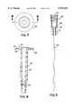
- FIG. 1is a side elevational view of the syringe of this invention
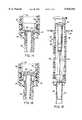
- FIG. 2is an axial cross-sectional view of the syringe of FIG. 1 illustrating the various working parts of the invention with the plunger substantially depressed and the needle protruding from the front end of the barrel;
- FIG. 3is an enlarged rear end view of the barrel of the syringe of FIG. 2;
- FIG. 4is an enlarged axial cross-sectional view of the barrel of the syringe taken on line 4--4 of FIG. 3;
- FIG. 5is an enlarged rear end view of the hollow plunger of the syringe of FIG. 2;
- FIG. 6is an enlarged axial cross-sectional view of the hollow plunger of the syringe taken on line 6--6 of FIG. 5;
- FIG. 7is an enlarged rear end view of a hollow stem which is separably attached adjacent to the front end of the syringe barrel;
- FIG. 8is an enlarged axial cross-sectional view of the hollow stem taken on line 8--8 of FIG. 7;
- FIG. 9is an enlarged axial cross-sectional view of an assembly of a needle mounted in a hub
- FIG. 10is an enlarged rear end view of a hollow needle cap which fits over the needle and snaps onto the hub of FIG. 9;
- FIG. 11is an enlarged partially broken away axial cross-sectional view of the hollow needle cap taken on line 11--11 of FIG. 10;
- FIG. 12is a cross-sectional view of the needle cap taken on line 12--12 of FIG. 11;
- FIG. 13is a enlarged cross-sectional partial view of the syringe shown in FIG. 2 to better emphasize the release mechanism for causing the stem and needle assembly to be released into the hollow plunger;
- FIG. 14is an enlarged fragmentary cross-sectional view similar to FIG. 13 with the plunger moved axially forward a sufficient distance that the end of the plunger is starting to sever the stem from the barrel;
- FIG. 15is an enlarged fragmentary cross-sectional view similar to FIG. 14 but with the plunger moved axially forward even farther so that the rear end of the stem has severed a front end wall of the hollow plunger and the stem has started to move into the plunger;
- FIG. 16is a cross sectional view of the syringe of the invention similar to FIG. 2 but showing the stem and needle assembly fully enclosed in the plunger and barrel and held in the retracted position by a compression spring;
- FIG. 17is an enlarged fragmentary axial cross section similar to FIGS. 14 and 15 but showing another embodiment of the stem and needle assembly release mechanism having multi-angled cutting edges;
- FIG. 18is an enlarged fragmentary axial cross section similar to FIGS. 14 and 15 but showing still another embodiment of the stem and needle assembly release mechanism which is designed to sever the plunger end wall before severing the stem from the barrel.
- the syringe 20has a hollow cylindrical barrel 22 (also shown in FIG. 3) which is open at the rear end and has a main body portion 24 and a hollow front end extension 26 of reduced diameter from the body portion 24.
- the barrelalso has transverse flanges 28 at the rear end thereof which are gripped by the fingers of a user of the syringe 20.
- a hollow plunger 30(also shown in FIGS. 5 and 6) is inserted into the open rear end of the barrel 22 and is axially slideable therein.
- the plunger 30has a resilient seal 32 encircling the plunger near the front end and sealing against an inner surface 34 of the barrel main body portion 24.
- the seal 32fits in an annular groove 36 (shown in FIG. 6) near the front end of the plunger 30.
- Both the barrel 22 and the plunger 30 as well as the other later described parts of the syringe 20are made preferably of radiation resistant thermoplastic material such as Polypropylene or the like by injection and coining molding or injection and compression molding or extrusion and compression molding of multiple cavities rotary stations.
- the plunger 30has a rear end cap 38 which is snapped in place by means of an annular groove 40 which receives an annular rib 42 (shown in FIG. 6).
- the plunger 30has an annular rib or protrusion 31 which holds the plunger in centered axial alignment within the barrel 22.
- This rib 31also serves to prevent the plunger 30 from being pulled out of the barrel 30 if the rib comes in contact with a reduced diameter portion 25 near the rear end of the barrel 22 as shown in FIG. 4.
- the front end of the hollow plunger 30is sealingly closed by a disc shaped end wall 44 which is preferably molded as an integral part of the plunger 30.
- the end wall 44has an annular notch 46 extending around the periphery thereof which provides a thin membrane portion and a notch effect which makes the wall 44 easier to sever from the plunger as will be explained later.
- FIGS. 7 and 8is a hollow stem 48 having a tubular body portion 50, a radially outwardly extending annular flange or disc 52 molded integrally on the rear end of the stem 48, and a threaded portion 54 on the front end thereof.
- the flange 52has an annular notch 55 which is similar to the notch 46 in the end wall 44 and produces an annular membrane and a notch effect.
- This notch 55 and the notch effectmakes it easier for the stem 48 to be severed from the barrel 22 and release the stem 48 from the barrel 22.
- the annular notches 46 and 55 and their notch effectcan be placed on the opposite side of the respective part on which they are shown in the drawings.
- the main objective of the notchesis to provide a thin membrane portion and notch effect which is easy to sever when the plunger 30 is depressed.
- the notches 46 and 55are circumferentially aligned with the annular cutting edges 78 and 80 so that the cutting edges pass through the thin membranes when cutting is performed.
- FIG. 9is a needle assembly 56 comprising a needle hub 58 to which is attached a needle 60 by suitable bonding adhesive.
- the hub 58has a threaded portion 62 which engages the threaded portion 54 on the stem 48.
- the threads in the present exampleare inclined at a steep angle and are commonly know as a "Luer-Lok" configuration.
- the needle and hub assembly 56is screwed onto the stem 48 which in turn is attached to the barrel 22 preferably by ultrasonic bonding.
- Annular ridge 64 on the flange 52makes contact with ledge 66 to permit ultrasonic bonding of the stem 48 to the barrel 22.
- a sheath or cap 68 as shown in FIGS. 10 through 12is shown in chain dotted lines in FIGS. 1 and 13 snapped onto an annular ridge 59 on the needle hub 58.
- the sheath 68has ribs 70 which makes it easy to grasp and rotate when screwing the needle assembly 56 onto the stem 48.
- the sheathhas a plurality of longitudinal grooves 72 inside the ribs 70.
- the grooves 72are positioned to match with a plurality of fins 74 extending radially outwardly from the hub 58 as shown in FIG. 9.
- an annular inwardly facing groove 76 near the rear end of the sheath 68snaps over the ridge 59 on the needle hub 58 and holds it in place.
- the engagement of the fins 74 and the grooves 72permits the sheath 68 and the needle assembly 56 to be rotated together as a unit to screw the needle assembly 56 onto the threaded portion 54 of the stem 48.
- the interior of the needle hub 58has a threaded portion 62 which engages the threaded portion 54 of the stem 48.
- needlescan be interchangeable by selecting and attaching the desired size of needle assembly 56 to the stem 48.
- FIG. 13shows an enlarged version of the syringe 20 shown in FIG. 2 with the plunger 30 approaching the flange 52 of the stem 48.
- the plunger 30 on the front end thereofhas a sharp annular cutting edge 78 on the plunger 30 which severs the flange 52 of the stem 48 when the plunger 30 is depressed to a certain position.
- the flange 52 of the stem 48has a cutting edge 80 which severs the wall 44 of the plunger 30.
- the cutting edges 78 and 80are both inclined at an angle of approximately 5 degrees to a plane which is perpendicular to the axis of the syringe 20. This angle of inclination is necessary to provide a pointed force and shearing action on both the plunger end wall 44 and the flange 52 when the plunger 30 is depressed forwardly beyond a certain distance.
- FIG. 13shows the plunger 30 as the forward end approaches the front end of the barrel main body 24. Assuming that a liquid medication has been drawn into a liquid chamber 82 between the barrel 22 and the plunger 30, as the plunger 30 approaches the front end of the barrel main body 24, most of the liquid medication has been injected into the patient.
- the cutting edge 78 on the front end of the plunger 30contacts and severs the flange 52 thereby releasing the stem 48 and permitting it to be propelled rearwardly by a compression spring 84 as shown in FIG. 14.
- the spring 84is held under compression between the flange 52 on the stem 48 and an annular retaining band 86 which is formed as a thickened portion on the inside of the front end extension 26.
- the cutting edge 80 on the rear end of the flange 52severs the front end wall 44 from the plunger 30 and permits the stem 48 and the needle assembly 56 to be propelled rearwardly by the compression spring 84 into the hollow interior 88 of the plunger 30 as shown in FIG. 15 where it comes to rest inside the hollow interior 88 of the plunger 30 as shown in FIG. 16 where it is held in a retracted position by the spring 84.
- the cutting edge 78can enter an annular channel 90 which provides clearance for easier forward movement of the plunger 30 and easier deflection of the flange 52 and also receives any remaining liquid medication from the liquid chamber 82.
- the important components which cause the release of the stem 48 and needle assembly 56 and the plunger end wall 44are the cutting edges 78 and 80 and the notch effect at the annular notches 46 and 55. These edges cooperate to permit the retraction of the needle 60 by being propelled rearwardly by the spring 84.
- the inclined plane in which the edges 78 and 80 lieis the primary reason that these edges create a pointed force and shearing action on the disk 52 and the wall 44 and in which the notch effect is provided on the notches 46 and 55, thereby providing a more positive and reliable release and retraction of the needle assembly 56 and stem 48.
- the annular cutting edge 80telescopes inside the annular cutting edge 78, and in the embodiment showing in FIGS. 2 through 16, this results in the severing of the stem disk 52 slightly before severing of the plunger end wall 44.
- FIG. 17another embodiment of the invention shows multi-angle cutting edges 78a and 78b on the plunger 30a and multi-angle cutting edges 80a and 80b on the stem disk 52a. These cutting edges perform the same function as the cutting edges 78 and 80 but with a different angle configuration.
- FIG. 18shows cutting edges 78c and 80c in which the axial length of the stem mounted cutting edge 80c is longer than cutting edge 78c on the plunger 30c. This causes the end wall 44c to be severed and released before the disk 52c.
- needle release and retraction meanscan be used without departing from the scope of the inventions as long as the syringe uses a hollow plunger with a means of hydraulically sealing off the interior of the plunger from the fluid chamber of the syringe.
Landscapes
- Health & Medical Sciences (AREA)
- Engineering & Computer Science (AREA)
- Heart & Thoracic Surgery (AREA)
- Vascular Medicine (AREA)
- Anesthesiology (AREA)
- Biomedical Technology (AREA)
- Environmental & Geological Engineering (AREA)
- Hematology (AREA)
- Life Sciences & Earth Sciences (AREA)
- Animal Behavior & Ethology (AREA)
- General Health & Medical Sciences (AREA)
- Public Health (AREA)
- Veterinary Medicine (AREA)
- Infusion, Injection, And Reservoir Apparatuses (AREA)
Abstract
Description
Claims (45)
Priority Applications (8)
| Application Number | Priority Date | Filing Date | Title |
|---|---|---|---|
| US09/137,429US5935104A (en) | 1998-08-21 | 1998-08-21 | Safety medical syringe with retractable needle |
| PCT/US1999/018659WO2000013724A1 (en) | 1998-08-21 | 1999-08-17 | Safety medical syringe with retractable needle |
| ES99942248TES2260929T3 (en) | 1998-08-21 | 1999-08-17 | MEDICAL SAFETY SYRINGE WITH RETRACTABLE NEEDLE. |
| DE69930393TDE69930393T2 (en) | 1998-08-21 | 1999-08-17 | MEDICAL SECURITY SYRINGE WITH RETRACTABLE NEEDLE |
| AT99942248TATE320279T1 (en) | 1998-08-21 | 1999-08-17 | MEDICAL SAFETY SYRINGE WITH RETRACTABLE NEEDLE |
| CA002338830ACA2338830C (en) | 1998-08-21 | 1999-08-17 | Safety medical syringe with retractable needle |
| JP2000568529AJP2002524154A (en) | 1998-08-21 | 1999-08-17 | Safety syringe |
| EP99942248AEP1105174B1 (en) | 1998-08-21 | 1999-08-17 | Safety medical syringe with retractable needle |
Applications Claiming Priority (1)
| Application Number | Priority Date | Filing Date | Title |
|---|---|---|---|
| US09/137,429US5935104A (en) | 1998-08-21 | 1998-08-21 | Safety medical syringe with retractable needle |
Publications (1)
| Publication Number | Publication Date |
|---|---|
| US5935104Atrue US5935104A (en) | 1999-08-10 |
Family
ID=22477398
Family Applications (1)
| Application Number | Title | Priority Date | Filing Date |
|---|---|---|---|
| US09/137,429Expired - LifetimeUS5935104A (en) | 1998-08-21 | 1998-08-21 | Safety medical syringe with retractable needle |
Country Status (8)
| Country | Link |
|---|---|
| US (1) | US5935104A (en) |
| EP (1) | EP1105174B1 (en) |
| JP (1) | JP2002524154A (en) |
| AT (1) | ATE320279T1 (en) |
| CA (1) | CA2338830C (en) |
| DE (1) | DE69930393T2 (en) |
| ES (1) | ES2260929T3 (en) |
| WO (1) | WO2000013724A1 (en) |
Cited By (57)
| Publication number | Priority date | Publication date | Assignee | Title |
|---|---|---|---|---|
| WO2000037131A1 (en)* | 1998-12-18 | 2000-06-29 | Becton, Dickinson And Company | Retracting needle syringe |
| WO2001062320A1 (en)* | 2000-02-22 | 2001-08-30 | Occupational & Medical Innovations Ltd | A single use syringe |
| WO2002004050A1 (en)* | 2000-07-10 | 2002-01-17 | Hillsands Corporation Pty Ltd | Syringe with retractable needle |
| EP1092443A3 (en)* | 1999-10-15 | 2002-04-03 | Becton Dickinson and Company | Retracting needle syringe |
| WO2001049348A3 (en)* | 2000-01-04 | 2002-04-25 | Becton Dickinson Co | Retracting needle syringe |
| US6409701B1 (en) | 2000-09-29 | 2002-06-25 | Becton, Dickinson And Company | Hypodermic syringe with selectively retractable needle |
| US6413237B1 (en) | 2000-08-31 | 2002-07-02 | Becton, Dickinson And Company | Hypodermic syringe with selectively retractable needle |
| US6432087B1 (en) | 2000-07-31 | 2002-08-13 | Becton, Dickinson And Company | Hypodermic syringe with selectively retractable needle |
| US20020173753A1 (en)* | 1999-10-15 | 2002-11-21 | Richard Caizza | Attachment for a medical device |
| GB2376889A (en)* | 2001-04-26 | 2002-12-31 | Nmt Group Plc | Fluid handling devices |
| EP1237601A4 (en)* | 1999-12-07 | 2003-01-22 | Mdc Invest Holdings Inc | Safety needle medical bearing devices |
| US6530903B2 (en) | 2000-02-24 | 2003-03-11 | Xiping Wang | Safety syringe |
| US20030050605A1 (en)* | 1999-12-08 | 2003-03-13 | John Targell | Closure assembly in particular for hypodermic syringes |
| US6558357B1 (en) | 2000-08-30 | 2003-05-06 | Becton Dickinson And Company | Hypodermic syringe with selectively retractable needle |
| US6585701B1 (en) | 1998-06-15 | 2003-07-01 | Edward D. Dysarz | Trap in modular hub chamber spring needle cannula |
| US6585690B1 (en) | 2000-06-29 | 2003-07-01 | Becton Dickinson And Company | Hypodermic syringe with selectivity retractable needle |
| US6589209B1 (en) | 2000-09-05 | 2003-07-08 | Edward D. Dysarz | Safety syringe with retraction trunk |
| US6645181B1 (en) | 1998-11-13 | 2003-11-11 | Elan Pharma International Limited | Drug delivery systems and methods |
| WO2003093108A1 (en)* | 2002-04-05 | 2003-11-13 | Comar, Inc. | Dispenser for medicaments and method and apparatus for making same |
| US6712787B1 (en)* | 2000-05-19 | 2004-03-30 | Edward D. Dysarz | Self destructive safety syringe |
| US20040069044A1 (en)* | 1999-04-29 | 2004-04-15 | Gilad Lavi | Device for measuring a volume of drug |
| US6800066B2 (en)* | 2001-04-26 | 2004-10-05 | Nmt Group Plc | Retractable needle syringe |
| WO2005072802A1 (en)* | 2004-01-20 | 2005-08-11 | Becton, Dickinson And Company | Syringe having a retractable needle |
| US20060155245A1 (en)* | 2002-07-04 | 2006-07-13 | Kevin Woehr | Catheter insertion device |
| US20060189935A1 (en)* | 2004-10-14 | 2006-08-24 | Janek Gregory A | Safety medical syringe with retractable needle |
| US20060229568A1 (en)* | 2005-04-11 | 2006-10-12 | Koopman Robert A | Compact syringe |
| WO2006119537A1 (en)* | 2005-05-13 | 2006-11-16 | Occupational & Medical Innovations Ltd | A single use syringe with improved needle retraction mechanism |
| US20070100293A1 (en)* | 2005-10-28 | 2007-05-03 | Becton, Dickinson And Company | Plunger for retracting needle syringe |
| US20070129675A1 (en)* | 2005-12-05 | 2007-06-07 | Becton, Dickinson And Company | Cutting element for a retracting needle syringe |
| US20080108944A1 (en)* | 2006-11-03 | 2008-05-08 | Kevin Woehr | Catheter assembly and components thereof |
| US20080287881A1 (en)* | 2007-05-14 | 2008-11-20 | Bruce Leigh Kiehne | Syringe for use with nuclear medicines |
| US20090118677A1 (en)* | 2004-11-04 | 2009-05-07 | Global Medisafe Holdings Pty Limited | Exchange needle retractable safety syringe |
| US20100076378A1 (en)* | 2007-03-21 | 2010-03-25 | Midland Medical Devices Holdings, Llc | Safety Medical Syringe with Retractable Needle and Including a Plunger that is Received within a Barrel |
| US7846135B2 (en) | 2006-02-24 | 2010-12-07 | Midland Medical Holding LLC | Retractable needle syringe with needle trap |
| US20100331778A1 (en)* | 2009-06-26 | 2010-12-30 | Becton, Dickinson And Company | Passive Reuse Prevention Syringe That Uses A Flange Lock |
| US20110092902A1 (en)* | 2006-07-20 | 2011-04-21 | Bruce Leigh Kiehne | Single use syringe |
| US8162882B2 (en) | 2010-06-23 | 2012-04-24 | Sta-Med, Llc | Automatic-locking safety needle covers and methods of use and manufacture |
| CN102573954A (en)* | 2009-08-13 | 2012-07-11 | 路易斯·恩里克·普韦达·埃斯特巴 | Medical biosafety automatic disposable syringe |
| US20120232482A1 (en)* | 2011-03-07 | 2012-09-13 | Richard Caizza | Retractable Syringe with Segmented Retaining Ledge |
| US8486024B2 (en) | 2011-04-27 | 2013-07-16 | Covidien Lp | Safety IV catheter assemblies |
| JP2013530022A (en)* | 2010-06-30 | 2013-07-25 | リトラクタブル テクノロジーズ,インコーポレイテッド | Medical device with retractable needle and movable plunger seal |
| TWI409090B (en)* | 2005-03-03 | 2013-09-21 | Midland Medical Device Holdings Llc | Safety medical syringe with retractable needle |
| US8628497B2 (en) | 2011-09-26 | 2014-01-14 | Covidien Lp | Safety catheter |
| US8663129B2 (en) | 2011-05-31 | 2014-03-04 | Sta-Med, Llc | Blood collection safety devices and methods of use and manufacture |
| US8715250B2 (en) | 2011-09-26 | 2014-05-06 | Covidien Lp | Safety catheter and needle assembly |
| USD708260S1 (en)* | 2013-01-22 | 2014-07-01 | Professional Gallery, Inc. | Highlighter pen |
| US8834422B2 (en) | 2011-10-14 | 2014-09-16 | Covidien Lp | Vascular access assembly and safety device |
| US8939938B2 (en) | 2006-10-12 | 2015-01-27 | Covidien Lp | Needle tip protector |
| USD728690S1 (en)* | 2012-08-07 | 2015-05-05 | Jackpen Limited | Writing instrument |
| EP2566542A4 (en)* | 2010-05-07 | 2015-09-16 | Intuitive Creations Pte Ltd | A retractable syringe with a cutting crown |
| US9649450B2 (en) | 2004-09-03 | 2017-05-16 | L.O.M. Laboratories Inc. | Single use pneumatic safety syringe providing gas-driven needle retraction |
| US9849248B2 (en) | 2013-11-18 | 2017-12-26 | Tessy Plastics Corporation | Dispenser assembly for liquids comprising flexible barrel and rigid plunger |
| US10335554B2 (en) | 2008-06-02 | 2019-07-02 | Sta-Med, Llc | Needle cover |
| US10709847B2 (en) | 2015-01-20 | 2020-07-14 | L.O.M. Laboratories Inc. | Retractable needle syringe with unitary propellant release module |
| US10765815B2 (en) | 2014-10-31 | 2020-09-08 | L.O.M. Laboratories Inc. | Retractable needle syringe |
| US11058825B2 (en) | 2015-11-27 | 2021-07-13 | Sanofi-Aventis Deutschland Gmbh | Cap for an injection device |
| KR20210133356A (en)* | 2020-04-28 | 2021-11-08 | 재단법인 아산사회복지재단 | Safety syringe |
Families Citing this family (2)
| Publication number | Priority date | Publication date | Assignee | Title |
|---|---|---|---|---|
| CN2712373Y (en)* | 2004-06-16 | 2005-07-27 | 董忠浩 | Safety syringe with automatic retracting needle |
| CN101128232B (en)* | 2004-10-14 | 2011-06-08 | 安全医学国际公司 | Safety medical syringe with retractable needle |
Citations (21)
| Publication number | Priority date | Publication date | Assignee | Title |
|---|---|---|---|---|
| US4728320A (en)* | 1987-04-17 | 1988-03-01 | Chen Chang Cheng | Syringe cap with hammer |
| US4838863A (en)* | 1987-09-21 | 1989-06-13 | Allard Edward F | Safe needle system for collecting fluids |
| US4921486A (en)* | 1989-06-23 | 1990-05-01 | Dechellis Francis M | Disposable syringe with retracting needle |
| US4950241A (en)* | 1988-12-27 | 1990-08-21 | Sherwood Medical Company | Disposable syringe |
| US4973316A (en)* | 1990-01-16 | 1990-11-27 | Dysarz Edward D | One handed retractable safety syringe |
| US4978343A (en)* | 1990-01-16 | 1990-12-18 | Dysarz Edward D | Trap in barrel one handed retractable safety syringe |
| US5000738A (en)* | 1989-05-11 | 1991-03-19 | Lavallo Frank | Protective syringe with frangible barrel |
| US5019044A (en)* | 1989-08-14 | 1991-05-28 | Tsao Chien Hua | Safety hypodermic syringe |
| US5024616A (en)* | 1988-11-15 | 1991-06-18 | International Medication Systems, Limited | Disposable sheath for hypodermic cannula used with a syringe |
| US5049133A (en)* | 1989-01-24 | 1991-09-17 | Villen Pascual Joee A | Single-use safety syringe |
| US5064419A (en)* | 1987-07-13 | 1991-11-12 | Gaarde Knud W | Disposable hypodermic syringe |
| US5180370A (en)* | 1992-05-18 | 1993-01-19 | Gillespie Elgene R | Safety hypodermic syringe with retractable needle |
| US5188599A (en)* | 1989-07-11 | 1993-02-23 | Med-Design, Inc. | Retractable needle system |
| US5190526A (en)* | 1992-09-18 | 1993-03-02 | Murray Kenneth W | Hypodermic safety syringe with retracting needle system |
| US5267961A (en)* | 1991-04-03 | 1993-12-07 | Shaw Thomas J | Nonreusable syringe with safety indicator |
| US5389076A (en)* | 1994-04-05 | 1995-02-14 | Shaw; Thomas J. | Single use medical device with retraction mechanism |
| US5423758A (en)* | 1993-12-16 | 1995-06-13 | Shaw; Thomas J. | Retractable fluid collection device |
| US5542927A (en)* | 1995-01-10 | 1996-08-06 | Specialized Health Products, Inc. | Self retracting syringe needle apparatus and methods |
| US5769822A (en)* | 1996-09-13 | 1998-06-23 | Mcgary; R. Kern | Non-reusable retractable safety syringe |
| US5800403A (en)* | 1991-12-23 | 1998-09-01 | Syringe Development Partners L.L.C. | Safety syringe |
| US5843034A (en)* | 1993-10-28 | 1998-12-01 | Lok-Tek International Ltd. | Hypodermic syringe with retractable needle mount |
Family Cites Families (1)
| Publication number | Priority date | Publication date | Assignee | Title |
|---|---|---|---|---|
| US5053010A (en)* | 1990-10-03 | 1991-10-01 | Triad Technology | Safety syringe with retractable needle |
- 1998
- 1998-08-21USUS09/137,429patent/US5935104A/ennot_activeExpired - Lifetime
- 1999
- 1999-08-17EPEP99942248Apatent/EP1105174B1/ennot_activeExpired - Lifetime
- 1999-08-17WOPCT/US1999/018659patent/WO2000013724A1/enactiveIP Right Grant
- 1999-08-17ESES99942248Tpatent/ES2260929T3/ennot_activeExpired - Lifetime
- 1999-08-17JPJP2000568529Apatent/JP2002524154A/enactivePending
- 1999-08-17CACA002338830Apatent/CA2338830C/ennot_activeExpired - Fee Related
- 1999-08-17DEDE69930393Tpatent/DE69930393T2/ennot_activeExpired - Lifetime
- 1999-08-17ATAT99942248Tpatent/ATE320279T1/ennot_activeIP Right Cessation
Patent Citations (21)
| Publication number | Priority date | Publication date | Assignee | Title |
|---|---|---|---|---|
| US4728320A (en)* | 1987-04-17 | 1988-03-01 | Chen Chang Cheng | Syringe cap with hammer |
| US5064419A (en)* | 1987-07-13 | 1991-11-12 | Gaarde Knud W | Disposable hypodermic syringe |
| US4838863A (en)* | 1987-09-21 | 1989-06-13 | Allard Edward F | Safe needle system for collecting fluids |
| US5024616A (en)* | 1988-11-15 | 1991-06-18 | International Medication Systems, Limited | Disposable sheath for hypodermic cannula used with a syringe |
| US4950241A (en)* | 1988-12-27 | 1990-08-21 | Sherwood Medical Company | Disposable syringe |
| US5049133A (en)* | 1989-01-24 | 1991-09-17 | Villen Pascual Joee A | Single-use safety syringe |
| US5000738A (en)* | 1989-05-11 | 1991-03-19 | Lavallo Frank | Protective syringe with frangible barrel |
| US4921486A (en)* | 1989-06-23 | 1990-05-01 | Dechellis Francis M | Disposable syringe with retracting needle |
| US5188599A (en)* | 1989-07-11 | 1993-02-23 | Med-Design, Inc. | Retractable needle system |
| US5019044A (en)* | 1989-08-14 | 1991-05-28 | Tsao Chien Hua | Safety hypodermic syringe |
| US4978343A (en)* | 1990-01-16 | 1990-12-18 | Dysarz Edward D | Trap in barrel one handed retractable safety syringe |
| US4973316A (en)* | 1990-01-16 | 1990-11-27 | Dysarz Edward D | One handed retractable safety syringe |
| US5267961A (en)* | 1991-04-03 | 1993-12-07 | Shaw Thomas J | Nonreusable syringe with safety indicator |
| US5800403A (en)* | 1991-12-23 | 1998-09-01 | Syringe Development Partners L.L.C. | Safety syringe |
| US5180370A (en)* | 1992-05-18 | 1993-01-19 | Gillespie Elgene R | Safety hypodermic syringe with retractable needle |
| US5190526A (en)* | 1992-09-18 | 1993-03-02 | Murray Kenneth W | Hypodermic safety syringe with retracting needle system |
| US5843034A (en)* | 1993-10-28 | 1998-12-01 | Lok-Tek International Ltd. | Hypodermic syringe with retractable needle mount |
| US5423758A (en)* | 1993-12-16 | 1995-06-13 | Shaw; Thomas J. | Retractable fluid collection device |
| US5389076A (en)* | 1994-04-05 | 1995-02-14 | Shaw; Thomas J. | Single use medical device with retraction mechanism |
| US5542927A (en)* | 1995-01-10 | 1996-08-06 | Specialized Health Products, Inc. | Self retracting syringe needle apparatus and methods |
| US5769822A (en)* | 1996-09-13 | 1998-06-23 | Mcgary; R. Kern | Non-reusable retractable safety syringe |
Cited By (130)
| Publication number | Priority date | Publication date | Assignee | Title |
|---|---|---|---|---|
| US6585701B1 (en) | 1998-06-15 | 2003-07-01 | Edward D. Dysarz | Trap in modular hub chamber spring needle cannula |
| US6723068B2 (en) | 1998-11-13 | 2004-04-20 | Elan Pharma International Limited | Drug delivery systems and methods |
| US6645181B1 (en) | 1998-11-13 | 2003-11-11 | Elan Pharma International Limited | Drug delivery systems and methods |
| JP2002532205A (en)* | 1998-12-18 | 2002-10-02 | ベクトン・ディキンソン・アンド・カンパニー | Retractable needle syringe |
| WO2000037131A1 (en)* | 1998-12-18 | 2000-06-29 | Becton, Dickinson And Company | Retracting needle syringe |
| AU762938B2 (en)* | 1998-12-18 | 2003-07-10 | Becton Dickinson & Company | Retracting needle syringe |
| US20040069044A1 (en)* | 1999-04-29 | 2004-04-15 | Gilad Lavi | Device for measuring a volume of drug |
| US6368303B1 (en) | 1999-10-15 | 2002-04-09 | Becton, Dickinson And Company | Retracting needle syringe |
| US6840291B2 (en) | 1999-10-15 | 2005-01-11 | Becton Dickinson And Company | Attachment for a medical device |
| EP1092443A3 (en)* | 1999-10-15 | 2002-04-03 | Becton Dickinson and Company | Retracting needle syringe |
| US20020173753A1 (en)* | 1999-10-15 | 2002-11-21 | Richard Caizza | Attachment for a medical device |
| US6632198B2 (en) | 1999-10-15 | 2003-10-14 | Becton Dickinson And Company | Retracting needle syringe |
| EP1323447A3 (en)* | 1999-10-15 | 2003-08-13 | Becton, Dickinson and Company | Retracting needle syringe |
| AU782903B2 (en)* | 1999-12-07 | 2005-09-08 | Mdc Investment Holdings, Inc. | Safety needle medical bearing devices |
| EP1237601A4 (en)* | 1999-12-07 | 2003-01-22 | Mdc Invest Holdings Inc | Safety needle medical bearing devices |
| US20030050605A1 (en)* | 1999-12-08 | 2003-03-13 | John Targell | Closure assembly in particular for hypodermic syringes |
| CN101172178B (en)* | 2000-01-04 | 2011-01-26 | 贝克顿迪肯森公司 | Injector with retractable needle and retraction type needle component |
| CN100358594C (en)* | 2000-01-04 | 2008-01-02 | 贝克顿迪肯森公司 | needle retractable syringe |
| AU779896B2 (en)* | 2000-01-04 | 2005-02-17 | Becton Dickinson & Company | Retracting needle syringe |
| WO2001049348A3 (en)* | 2000-01-04 | 2002-04-25 | Becton Dickinson Co | Retracting needle syringe |
| AU775427B2 (en)* | 2000-02-22 | 2004-07-29 | Occupational & Medical Innovations Ltd | A single use syringe |
| WO2001062320A1 (en)* | 2000-02-22 | 2001-08-30 | Occupational & Medical Innovations Ltd | A single use syringe |
| US6994690B2 (en)* | 2000-02-22 | 2006-02-07 | Occupational & Medical Innovations Ltd | Single use syringe |
| US20020193736A1 (en)* | 2000-02-22 | 2002-12-19 | Kiehne Bruce Leigh | Single use syringe |
| AU775427C (en)* | 2000-02-22 | 2005-09-22 | Occupational & Medical Innovations Ltd | A single use syringe |
| US6530903B2 (en) | 2000-02-24 | 2003-03-11 | Xiping Wang | Safety syringe |
| US6712787B1 (en)* | 2000-05-19 | 2004-03-30 | Edward D. Dysarz | Self destructive safety syringe |
| US6585690B1 (en) | 2000-06-29 | 2003-07-01 | Becton Dickinson And Company | Hypodermic syringe with selectivity retractable needle |
| WO2002004050A1 (en)* | 2000-07-10 | 2002-01-17 | Hillsands Corporation Pty Ltd | Syringe with retractable needle |
| US6432087B1 (en) | 2000-07-31 | 2002-08-13 | Becton, Dickinson And Company | Hypodermic syringe with selectively retractable needle |
| US6558357B1 (en) | 2000-08-30 | 2003-05-06 | Becton Dickinson And Company | Hypodermic syringe with selectively retractable needle |
| US6413237B1 (en) | 2000-08-31 | 2002-07-02 | Becton, Dickinson And Company | Hypodermic syringe with selectively retractable needle |
| US6589209B1 (en) | 2000-09-05 | 2003-07-08 | Edward D. Dysarz | Safety syringe with retraction trunk |
| US6409701B1 (en) | 2000-09-29 | 2002-06-25 | Becton, Dickinson And Company | Hypodermic syringe with selectively retractable needle |
| GB2376889A (en)* | 2001-04-26 | 2002-12-31 | Nmt Group Plc | Fluid handling devices |
| US6800066B2 (en)* | 2001-04-26 | 2004-10-05 | Nmt Group Plc | Retractable needle syringe |
| US20050054980A1 (en)* | 2001-04-26 | 2005-03-10 | John Targell | Hub assembly for a retractable needle syringe and method of making |
| US20040010238A1 (en)* | 2002-04-05 | 2004-01-15 | Manera David A. | Dispenser for medicaments and method and apparatus for making same |
| US7070581B2 (en) | 2002-04-05 | 2006-07-04 | Comar, Inc. | Dispenser for medicaments and method and apparatus for making same |
| US20090062749A1 (en)* | 2002-04-05 | 2009-03-05 | Comar, Inc. | Dispenser for medicaments and method and apparatus for making same |
| US7438552B2 (en) | 2002-04-05 | 2008-10-21 | Comar, Inc. | Dispenser for medicaments and method and apparatus for making same |
| WO2003093108A1 (en)* | 2002-04-05 | 2003-11-13 | Comar, Inc. | Dispenser for medicaments and method and apparatus for making same |
| US8517997B2 (en) | 2002-04-05 | 2013-08-27 | Comar, Inc. | Dispenser for medicaments and method and apparatus for making same |
| US10166370B2 (en) | 2002-07-04 | 2019-01-01 | B. Braun Melsungen Ag | Catheter insertion device |
| US7736339B2 (en) | 2002-07-04 | 2010-06-15 | B.Braun Melsungen Ag | Catheter insertion device |
| US9149626B2 (en) | 2002-07-04 | 2015-10-06 | B. Braun Melsungen Ag | Catheter insertion device |
| US8540728B2 (en) | 2002-07-04 | 2013-09-24 | B. Braun Melsungen Ag | Catheter insertion device |
| US9149625B2 (en) | 2002-07-04 | 2015-10-06 | B. Braun Melsungen Ag | Catheter insertion device |
| US10080869B2 (en) | 2002-07-04 | 2018-09-25 | B. Braun Melsungen Ag | Catheter insertion device |
| US8337463B2 (en) | 2002-07-04 | 2012-12-25 | B. Braun Melsungen Ag | Catheter insertion device |
| US20100249707A1 (en)* | 2002-07-04 | 2010-09-30 | Kevin Woehr | Catheter insertion device |
| US8333735B2 (en) | 2002-07-04 | 2012-12-18 | B. Braun Melsungen Ag | Catheter insertion device |
| US20060155245A1 (en)* | 2002-07-04 | 2006-07-13 | Kevin Woehr | Catheter insertion device |
| US8328762B2 (en) | 2002-07-04 | 2012-12-11 | B. Braun Melsungen Ag | Catheter insertion device |
| WO2005072802A1 (en)* | 2004-01-20 | 2005-08-11 | Becton, Dickinson And Company | Syringe having a retractable needle |
| US7604613B2 (en) | 2004-01-20 | 2009-10-20 | Beckton, Dickinson And Company | Syringe having a retractable needle |
| US9649450B2 (en) | 2004-09-03 | 2017-05-16 | L.O.M. Laboratories Inc. | Single use pneumatic safety syringe providing gas-driven needle retraction |
| US10335555B2 (en) | 2004-09-03 | 2019-07-02 | L.O.M. Laboratories Inc. | Single-use pneumatic safety syringe providing gas-driven needle retraction |
| US20110021989A1 (en)* | 2004-10-14 | 2011-01-27 | Janek Gregory A | Safety medical syringe with retractable needle |
| US20060189935A1 (en)* | 2004-10-14 | 2006-08-24 | Janek Gregory A | Safety medical syringe with retractable needle |
| US8684966B2 (en)* | 2004-10-14 | 2014-04-01 | Midland Medical Devices Holdings, Llc | Safety medical syringe with retractable needle |
| US7803132B2 (en)* | 2004-10-14 | 2010-09-28 | Midland Medical Device Holdings, LLC | Safety medical syringe with retractable needle |
| US20090118677A1 (en)* | 2004-11-04 | 2009-05-07 | Global Medisafe Holdings Pty Limited | Exchange needle retractable safety syringe |
| TWI409090B (en)* | 2005-03-03 | 2013-09-21 | Midland Medical Device Holdings Llc | Safety medical syringe with retractable needle |
| US7972312B2 (en)* | 2005-04-11 | 2011-07-05 | Koopman Robert A | Compac syringe |
| US20060229568A1 (en)* | 2005-04-11 | 2006-10-12 | Koopman Robert A | Compact syringe |
| US7544182B2 (en) | 2005-05-13 | 2009-06-09 | Occupational & Medical Innovations Ltd | Single use syringe with improved needle retraction mechanism |
| WO2006119537A1 (en)* | 2005-05-13 | 2006-11-16 | Occupational & Medical Innovations Ltd | A single use syringe with improved needle retraction mechanism |
| US20070244433A1 (en)* | 2005-05-13 | 2007-10-18 | Kiehne Bruce L | Single use syringe with improved needle retraction mechanism |
| US20060258984A1 (en)* | 2005-05-13 | 2006-11-16 | Kiehne Bruce L | Single use syringe with improved needle retraction mechanism |
| US7713245B2 (en)* | 2005-10-28 | 2010-05-11 | Becton, Dickinson And Company | Plunger for retracting needle syringe |
| US20070100293A1 (en)* | 2005-10-28 | 2007-05-03 | Becton, Dickinson And Company | Plunger for retracting needle syringe |
| WO2007067449A3 (en)* | 2005-12-05 | 2007-11-15 | Becton Dickinson Co | Cutting element for a retracting needle syringe |
| US20070129675A1 (en)* | 2005-12-05 | 2007-06-07 | Becton, Dickinson And Company | Cutting element for a retracting needle syringe |
| US9919114B2 (en) | 2005-12-05 | 2018-03-20 | Becton, Dickinson And Company | Cutting element for a retracting needle syringe |
| US8277409B2 (en)* | 2005-12-05 | 2012-10-02 | Becton, Dickinson And Company | Cutting element for a retracting needle syringe |
| US9072840B2 (en) | 2005-12-05 | 2015-07-07 | Becton, Dickinson And Company | Cutting element for a retracting needle syringe |
| AU2006322099B2 (en)* | 2005-12-05 | 2012-02-23 | Becton, Dickinson And Company | Cutting element for a retracting needle syringe |
| US7846135B2 (en) | 2006-02-24 | 2010-12-07 | Midland Medical Holding LLC | Retractable needle syringe with needle trap |
| US20110092902A1 (en)* | 2006-07-20 | 2011-04-21 | Bruce Leigh Kiehne | Single use syringe |
| US8939938B2 (en) | 2006-10-12 | 2015-01-27 | Covidien Lp | Needle tip protector |
| US10682500B2 (en) | 2006-11-03 | 2020-06-16 | B. Braun Melsungen Ag | Catheter assembly and components thereof |
| US8308691B2 (en) | 2006-11-03 | 2012-11-13 | B. Braun Melsungen Ag | Catheter assembly and components thereof |
| US9370641B2 (en) | 2006-11-03 | 2016-06-21 | B. Braun Melsungen Ag | Catheter assembly and components thereof |
| US8460247B2 (en) | 2006-11-03 | 2013-06-11 | B Braun Melsungen Ag | Catheter assembly and components thereof |
| US8591468B2 (en) | 2006-11-03 | 2013-11-26 | B. Braun Melsungen Ag | Catheter assembly and components thereof |
| US8597249B2 (en) | 2006-11-03 | 2013-12-03 | B. Braun Melsungen Ag | Catheter assembly and components thereof |
| US20080108944A1 (en)* | 2006-11-03 | 2008-05-08 | Kevin Woehr | Catheter assembly and components thereof |
| US20100076378A1 (en)* | 2007-03-21 | 2010-03-25 | Midland Medical Devices Holdings, Llc | Safety Medical Syringe with Retractable Needle and Including a Plunger that is Received within a Barrel |
| US20080287881A1 (en)* | 2007-05-14 | 2008-11-20 | Bruce Leigh Kiehne | Syringe for use with nuclear medicines |
| US10335554B2 (en) | 2008-06-02 | 2019-07-02 | Sta-Med, Llc | Needle cover |
| US11090443B2 (en) | 2008-06-02 | 2021-08-17 | Sta-Med, Llc | Needle cover |
| US11992665B2 (en) | 2008-06-02 | 2024-05-28 | Sta-Med, Llc | Needle cover |
| AU2009348448B2 (en)* | 2009-06-26 | 2013-05-23 | Becton, Dickinson And Company | Passive reuse prevention syringe that uses a flange lock |
| US8790302B2 (en) | 2009-06-26 | 2014-07-29 | Becton, Dickinson And Company | Passive reuse prevention syringe that uses a flange lock |
| AU2009348448C1 (en)* | 2009-06-26 | 2015-12-24 | Becton, Dickinson And Company | Passive reuse prevention syringe that uses a flange lock |
| US8066668B2 (en)* | 2009-06-26 | 2011-11-29 | Becton, Dickinson And Company | Passive reuse prevention syringe that uses a flange lock |
| US20100331778A1 (en)* | 2009-06-26 | 2010-12-30 | Becton, Dickinson And Company | Passive Reuse Prevention Syringe That Uses A Flange Lock |
| CN102573954A (en)* | 2009-08-13 | 2012-07-11 | 路易斯·恩里克·普韦达·埃斯特巴 | Medical biosafety automatic disposable syringe |
| EP2566542A4 (en)* | 2010-05-07 | 2015-09-16 | Intuitive Creations Pte Ltd | A retractable syringe with a cutting crown |
| US8747355B2 (en) | 2010-06-23 | 2014-06-10 | Sta-Med, Llc | Automatic-locking safety needle covers and methods of use and manufacture |
| US9694140B2 (en) | 2010-06-23 | 2017-07-04 | Sta-Med, Llc | Automatic-locking safety needle covers and methods of use and manufacture |
| US8162882B2 (en) | 2010-06-23 | 2012-04-24 | Sta-Med, Llc | Automatic-locking safety needle covers and methods of use and manufacture |
| US11992666B2 (en) | 2010-06-23 | 2024-05-28 | Sta-Med, Llc | Automatic-locking safety needle covers and methods of use and manufacture |
| US10682470B2 (en) | 2010-06-23 | 2020-06-16 | Sta-Med, Llc | Automatic-locking safety needle covers and methods of use and manufacture |
| JP2013530022A (en)* | 2010-06-30 | 2013-07-25 | リトラクタブル テクノロジーズ,インコーポレイテッド | Medical device with retractable needle and movable plunger seal |
| EP2588174A4 (en)* | 2010-06-30 | 2014-01-22 | Retractable Technologies Inc | MEDICAL DEVICE WITH RETRACTABLE NEEDLE AND MOBILE PISTON SEAL |
| US9642970B2 (en) | 2010-06-30 | 2017-05-09 | Retractable Technologies, Inc. | Syringe with retractable needle and moveable plunger seal |
| US20120232482A1 (en)* | 2011-03-07 | 2012-09-13 | Richard Caizza | Retractable Syringe with Segmented Retaining Ledge |
| US8535267B2 (en)* | 2011-03-07 | 2013-09-17 | Midland Medical Devices Holdings, Llc | Retractable syringe with segmented retaining ledge |
| US8926563B2 (en) | 2011-04-27 | 2015-01-06 | Covidien Lp | Safety IV catheter assemblies |
| US8486024B2 (en) | 2011-04-27 | 2013-07-16 | Covidien Lp | Safety IV catheter assemblies |
| US12274550B2 (en) | 2011-05-31 | 2025-04-15 | Sta-Med, Llc | Blood collection safety devices and methods of use and manufacture |
| US9445760B2 (en) | 2011-05-31 | 2016-09-20 | Sta-Med, Llc | Blood collection safety devices and methods of use and manufacture |
| US8663129B2 (en) | 2011-05-31 | 2014-03-04 | Sta-Med, Llc | Blood collection safety devices and methods of use and manufacture |
| US9848810B2 (en) | 2011-05-31 | 2017-12-26 | Sta-Med, Llc | Blood collection safety devices and methods of use and manufacture |
| US11116432B2 (en) | 2011-05-31 | 2021-09-14 | Sta-Med, Llc | Blood collection safety devices and methods of use and manufacture |
| US8628497B2 (en) | 2011-09-26 | 2014-01-14 | Covidien Lp | Safety catheter |
| US9375552B2 (en) | 2011-09-26 | 2016-06-28 | Covidien Lp | Safety needle assembly |
| US8715250B2 (en) | 2011-09-26 | 2014-05-06 | Covidien Lp | Safety catheter and needle assembly |
| US8834422B2 (en) | 2011-10-14 | 2014-09-16 | Covidien Lp | Vascular access assembly and safety device |
| USD728690S1 (en)* | 2012-08-07 | 2015-05-05 | Jackpen Limited | Writing instrument |
| USD708260S1 (en)* | 2013-01-22 | 2014-07-01 | Professional Gallery, Inc. | Highlighter pen |
| US9849248B2 (en) | 2013-11-18 | 2017-12-26 | Tessy Plastics Corporation | Dispenser assembly for liquids comprising flexible barrel and rigid plunger |
| US10765815B2 (en) | 2014-10-31 | 2020-09-08 | L.O.M. Laboratories Inc. | Retractable needle syringe |
| US10709847B2 (en) | 2015-01-20 | 2020-07-14 | L.O.M. Laboratories Inc. | Retractable needle syringe with unitary propellant release module |
| US11904151B2 (en) | 2015-11-27 | 2024-02-20 | Sanofi-Aventis Deutschland Gmbh | Cap for an injection device |
| US11058825B2 (en) | 2015-11-27 | 2021-07-13 | Sanofi-Aventis Deutschland Gmbh | Cap for an injection device |
| KR102421258B1 (en) | 2020-04-28 | 2022-07-15 | 재단법인 아산사회복지재단 | Safety syringe |
| KR20210133356A (en)* | 2020-04-28 | 2021-11-08 | 재단법인 아산사회복지재단 | Safety syringe |
Also Published As
| Publication number | Publication date |
|---|---|
| DE69930393T2 (en) | 2006-12-07 |
| ES2260929T3 (en) | 2006-11-01 |
| CA2338830A1 (en) | 2000-03-16 |
| WO2000013724A1 (en) | 2000-03-16 |
| DE69930393D1 (en) | 2006-05-11 |
| JP2002524154A (en) | 2002-08-06 |
| EP1105174A1 (en) | 2001-06-13 |
| CA2338830C (en) | 2008-02-19 |
| EP1105174A4 (en) | 2001-11-28 |
| EP1105174B1 (en) | 2006-03-15 |
| ATE320279T1 (en) | 2006-04-15 |
Similar Documents
| Publication | Publication Date | Title |
|---|---|---|
| US5935104A (en) | Safety medical syringe with retractable needle | |
| US5180370A (en) | Safety hypodermic syringe with retractable needle | |
| US4969877A (en) | Syringe | |
| US4026287A (en) | Syringe with retractable cannula | |
| US5458576A (en) | Safety syringe with retracting needle | |
| US5882342A (en) | Safety medical syringe with retractable needle | |
| US6096005A (en) | Retractable needle medical devices | |
| EP1225933B1 (en) | Retractable dental syringe | |
| EP0551421B1 (en) | Safety syringe with retractable needle | |
| US6036674A (en) | Retracting needle syringe | |
| US5188599A (en) | Retractable needle system | |
| EP1092443B1 (en) | Retracting needle syringe | |
| US6123688A (en) | Pre-filled retractable needle injection devices | |
| US5531705A (en) | Syringe unit | |
| EP2522382B1 (en) | Injection device | |
| US6221052B1 (en) | Retracting needle syringe | |
| CN102573966B (en) | Medical device with retractable needle and movable plunger seal | |
| US5984898A (en) | Retractable needle and syringe combination | |
| US20030078540A1 (en) | Retractable needle assembly | |
| MXPA01008819A (en) | Hypodermic syringe with selectively retractable needle. | |
| EP1011766A1 (en) | Syringe with retractable needle assembly | |
| MXPA01006743A (en) | Hypodermic syringe with selectively retractable needle. | |
| JP2005523118A (en) | Fluid transfer adapter for use with a syringe barrel | |
| MXPA01006619A (en) | Hypodermic syringe with a selectively retractable needle. | |
| EP0927054B1 (en) | Pre-filled medical injection device having retractable needle |
Legal Events
| Date | Code | Title | Description |
|---|---|---|---|
| AS | Assignment | Owner name:SAFETY MEDICAL MANUFACTURING, INCORPORATED, FLORID Free format text:ASSIGNMENT OF ASSIGNORS INTEREST;ASSIGNORS:JANEK, GREGORY A.;LEE, MORRIS M.;GILLESPIE, ELGENE R.;REEL/FRAME:009408/0594;SIGNING DATES FROM 19980812 TO 19980820 | |
| AS | Assignment | Owner name:SAFETY MEDICAL INTERNATIONAL, FLORIDA Free format text:ASSIGNMENT OF ASSIGNORS INTEREST;ASSIGNOR:SAFETY MEDICAL MANUFACTURING, INC.;REEL/FRAME:013532/0130 Effective date:20021120 | |
| FPAY | Fee payment | Year of fee payment:4 | |
| REMI | Maintenance fee reminder mailed | ||
| FEPP | Fee payment procedure | Free format text:PETITION RELATED TO MAINTENANCE FEES FILED (ORIGINAL EVENT CODE: PMFP); ENTITY STATUS OF PATENT OWNER: SMALL ENTITY | |
| REMI | Maintenance fee reminder mailed | ||
| REIN | Reinstatement after maintenance fee payment confirmed | ||
| FPAY | Fee payment | Year of fee payment:8 | |
| FP | Lapsed due to failure to pay maintenance fee | Effective date:20070810 | |
| FEPP | Fee payment procedure | Free format text:PETITION RELATED TO MAINTENANCE FEES GRANTED (ORIGINAL EVENT CODE: PMFG); ENTITY STATUS OF PATENT OWNER: SMALL ENTITY | |
| PRDP | Patent reinstated due to the acceptance of a late maintenance fee | Effective date:20080109 | |
| STCF | Information on status: patent grant | Free format text:PATENTED CASE | |
| AS | Assignment | Owner name:CLARK, MITCHELL R., TEXAS Free format text:ASSIGNMENT OF ASSIGNORS INTEREST;ASSIGNOR:SAFETY MEDICAL INTERNATIONAL, INC.;REEL/FRAME:022951/0671 Effective date:20090527 | |
| AS | Assignment | Owner name:MIDLAND MEDICAL DEVICES HOLDINGS, LLC, TEXAS Free format text:ASSIGNMENT OF ASSIGNORS INTEREST;ASSIGNOR:CLARK, MITCHELL R.;REEL/FRAME:022960/0192 Effective date:20090604 | |
| FEPP | Fee payment procedure | Free format text:PAYOR NUMBER ASSIGNED (ORIGINAL EVENT CODE: ASPN); ENTITY STATUS OF PATENT OWNER: SMALL ENTITY | |
| FPAY | Fee payment | Year of fee payment:12 |