US5935079A - Systems and methods for positioning multiple electrode structures in electrical contact with the myocardium - Google Patents
Systems and methods for positioning multiple electrode structures in electrical contact with the myocardiumDownload PDFInfo
- Publication number
- US5935079A US5935079AUS08/925,196US92519697AUS5935079AUS 5935079 AUS5935079 AUS 5935079AUS 92519697 AUS92519697 AUS 92519697AUS 5935079 AUS5935079 AUS 5935079A
- Authority
- US
- United States
- Prior art keywords
- electrode
- myocardium
- contact
- electrical contact
- signal
- Prior art date
- Legal status (The legal status is an assumption and is not a legal conclusion. Google has not performed a legal analysis and makes no representation as to the accuracy of the status listed.)
- Expired - Lifetime
Links
- 210000004165myocardiumAnatomy0.000titleclaimsabstractdescription81
- 238000000034methodMethods0.000titleclaimsabstractdescription53
- 210000002216heartAnatomy0.000claimsabstractdescription36
- 150000001875compoundsChemical class0.000claimsabstractdescription26
- 239000008280bloodSubstances0.000claimsdescription20
- 210000004369bloodAnatomy0.000claimsdescription20
- 238000012545processingMethods0.000claimsdescription14
- 230000002107myocardial effectEffects0.000claimsdescription7
- 230000002596correlated effectEffects0.000claimsdescription2
- 239000007933dermal patchSubstances0.000claims1
- 210000001519tissueAnatomy0.000description37
- 238000013507mappingMethods0.000description16
- 210000005003heart tissueAnatomy0.000description10
- 230000008569processEffects0.000description9
- 238000002847impedance measurementMethods0.000description8
- 239000000523sampleSubstances0.000description6
- 238000002679ablationMethods0.000description5
- 230000000747cardiac effectEffects0.000description4
- 210000005242cardiac chamberAnatomy0.000description3
- 230000008859changeEffects0.000description3
- 210000005240left ventricleAnatomy0.000description3
- 210000003462veinAnatomy0.000description3
- 238000004458analytical methodMethods0.000description2
- 210000001367arteryAnatomy0.000description2
- 206010061592cardiac fibrillationDiseases0.000description2
- 239000002131composite materialSubstances0.000description2
- 230000002600fibrillogenic effectEffects0.000description2
- 230000006698inductionEffects0.000description2
- 230000002452interceptive effectEffects0.000description2
- 238000005259measurementMethods0.000description2
- 230000028161membrane depolarizationEffects0.000description2
- 230000037361pathwayEffects0.000description2
- 230000035479physiological effects, processes and functionsEffects0.000description2
- BASFCYQUMIYNBI-UHFFFAOYSA-NplatinumChemical compound[Pt]BASFCYQUMIYNBI-UHFFFAOYSA-N0.000description2
- 230000001594aberrant effectEffects0.000description1
- 238000003491arrayMethods0.000description1
- 230000000712assemblyEffects0.000description1
- 238000000429assemblyMethods0.000description1
- 238000010009beatingMethods0.000description1
- 230000005540biological transmissionEffects0.000description1
- 230000000052comparative effectEffects0.000description1
- 230000006835compressionEffects0.000description1
- 238000007906compressionMethods0.000description1
- 230000001143conditioned effectEffects0.000description1
- 230000008878couplingEffects0.000description1
- 238000010168coupling processMethods0.000description1
- 238000005859coupling reactionMethods0.000description1
- 230000007423decreaseEffects0.000description1
- 230000005684electric fieldEffects0.000description1
- 210000001174endocardiumAnatomy0.000description1
- 238000011156evaluationMethods0.000description1
- PCHJSUWPFVWCPO-UHFFFAOYSA-NgoldChemical compound[Au]PCHJSUWPFVWCPO-UHFFFAOYSA-N0.000description1
- 229910052737goldInorganic materials0.000description1
- 239000010931goldSubstances0.000description1
- 230000003902lesionEffects0.000description1
- 239000000463materialSubstances0.000description1
- 230000007246mechanismEffects0.000description1
- 229910052751metalInorganic materials0.000description1
- 239000002184metalSubstances0.000description1
- 229910052697platinumInorganic materials0.000description1
- 230000004044responseEffects0.000description1
- 230000033764rhythmic processEffects0.000description1
- 238000012883sequential measurementMethods0.000description1
- 229910001220stainless steelInorganic materials0.000description1
- 239000010935stainless steelSubstances0.000description1
- 230000003068static effectEffects0.000description1
- 238000001356surgical procedureMethods0.000description1
- 238000012360testing methodMethods0.000description1
- 230000001225therapeutic effectEffects0.000description1
- 238000002560therapeutic procedureMethods0.000description1
Images


Classifications
- A—HUMAN NECESSITIES
- A61—MEDICAL OR VETERINARY SCIENCE; HYGIENE
- A61B—DIAGNOSIS; SURGERY; IDENTIFICATION
- A61B5/00—Measuring for diagnostic purposes; Identification of persons
- A61B5/68—Arrangements of detecting, measuring or recording means, e.g. sensors, in relation to patient
- A61B5/6846—Arrangements of detecting, measuring or recording means, e.g. sensors, in relation to patient specially adapted to be brought in contact with an internal body part, i.e. invasive
- A61B5/6885—Monitoring or controlling sensor contact pressure
- A—HUMAN NECESSITIES
- A61—MEDICAL OR VETERINARY SCIENCE; HYGIENE
- A61B—DIAGNOSIS; SURGERY; IDENTIFICATION
- A61B5/00—Measuring for diagnostic purposes; Identification of persons
- A61B5/24—Detecting, measuring or recording bioelectric or biomagnetic signals of the body or parts thereof
- A61B5/25—Bioelectric electrodes therefor
- A61B5/276—Protection against electrode failure
- A—HUMAN NECESSITIES
- A61—MEDICAL OR VETERINARY SCIENCE; HYGIENE
- A61B—DIAGNOSIS; SURGERY; IDENTIFICATION
- A61B5/00—Measuring for diagnostic purposes; Identification of persons
- A61B5/24—Detecting, measuring or recording bioelectric or biomagnetic signals of the body or parts thereof
- A61B5/25—Bioelectric electrodes therefor
- A61B5/279—Bioelectric electrodes therefor specially adapted for particular uses
- A61B5/28—Bioelectric electrodes therefor specially adapted for particular uses for electrocardiography [ECG]
- A61B5/283—Invasive
- A61B5/287—Holders for multiple electrodes, e.g. electrode catheters for electrophysiological study [EPS]
- A—HUMAN NECESSITIES
- A61—MEDICAL OR VETERINARY SCIENCE; HYGIENE
- A61B—DIAGNOSIS; SURGERY; IDENTIFICATION
- A61B5/00—Measuring for diagnostic purposes; Identification of persons
- A61B5/24—Detecting, measuring or recording bioelectric or biomagnetic signals of the body or parts thereof
- A61B5/30—Input circuits therefor
- A61B5/307—Input circuits therefor specially adapted for particular uses
- A61B5/308—Input circuits therefor specially adapted for particular uses for electrocardiography [ECG]
- A—HUMAN NECESSITIES
- A61—MEDICAL OR VETERINARY SCIENCE; HYGIENE
- A61B—DIAGNOSIS; SURGERY; IDENTIFICATION
- A61B5/00—Measuring for diagnostic purposes; Identification of persons
- A61B5/68—Arrangements of detecting, measuring or recording means, e.g. sensors, in relation to patient
- A61B5/6846—Arrangements of detecting, measuring or recording means, e.g. sensors, in relation to patient specially adapted to be brought in contact with an internal body part, i.e. invasive
- A61B5/6847—Arrangements of detecting, measuring or recording means, e.g. sensors, in relation to patient specially adapted to be brought in contact with an internal body part, i.e. invasive mounted on an invasive device
- A61B5/6852—Catheters
- A61B5/6858—Catheters with a distal basket, e.g. expandable basket
- A—HUMAN NECESSITIES
- A61—MEDICAL OR VETERINARY SCIENCE; HYGIENE
- A61B—DIAGNOSIS; SURGERY; IDENTIFICATION
- A61B18/00—Surgical instruments, devices or methods for transferring non-mechanical forms of energy to or from the body
- A61B18/04—Surgical instruments, devices or methods for transferring non-mechanical forms of energy to or from the body by heating
- A61B18/12—Surgical instruments, devices or methods for transferring non-mechanical forms of energy to or from the body by heating by passing a current through the tissue to be heated, e.g. high-frequency current
- A61B18/14—Probes or electrodes therefor
- A61B18/1492—Probes or electrodes therefor having a flexible, catheter-like structure, e.g. for heart ablation
- A—HUMAN NECESSITIES
- A61—MEDICAL OR VETERINARY SCIENCE; HYGIENE
- A61B—DIAGNOSIS; SURGERY; IDENTIFICATION
- A61B18/00—Surgical instruments, devices or methods for transferring non-mechanical forms of energy to or from the body
- A61B18/04—Surgical instruments, devices or methods for transferring non-mechanical forms of energy to or from the body by heating
- A61B18/12—Surgical instruments, devices or methods for transferring non-mechanical forms of energy to or from the body by heating by passing a current through the tissue to be heated, e.g. high-frequency current
- A61B18/14—Probes or electrodes therefor
- A61B2018/1465—Deformable electrodes
- A—HUMAN NECESSITIES
- A61—MEDICAL OR VETERINARY SCIENCE; HYGIENE
- A61B—DIAGNOSIS; SURGERY; IDENTIFICATION
- A61B90/00—Instruments, implements or accessories specially adapted for surgery or diagnosis and not covered by any of the groups A61B1/00 - A61B50/00, e.g. for luxation treatment or for protecting wound edges
- A61B90/06—Measuring instruments not otherwise provided for
- A61B2090/064—Measuring instruments not otherwise provided for for measuring force, pressure or mechanical tension
- A61B2090/065—Measuring instruments not otherwise provided for for measuring force, pressure or mechanical tension for measuring contact or contact pressure
- A—HUMAN NECESSITIES
- A61—MEDICAL OR VETERINARY SCIENCE; HYGIENE
- A61B—DIAGNOSIS; SURGERY; IDENTIFICATION
- A61B2562/00—Details of sensors; Constructional details of sensor housings or probes; Accessories for sensors
- A61B2562/04—Arrangements of multiple sensors of the same type
- A61B2562/043—Arrangements of multiple sensors of the same type in a linear array
- A—HUMAN NECESSITIES
- A61—MEDICAL OR VETERINARY SCIENCE; HYGIENE
- A61B—DIAGNOSIS; SURGERY; IDENTIFICATION
- A61B5/00—Measuring for diagnostic purposes; Identification of persons
- A61B5/24—Detecting, measuring or recording bioelectric or biomagnetic signals of the body or parts thereof
- A61B5/30—Input circuits therefor
- A61B5/304—Switching circuits
Definitions
- the inventionrelates to systems and methods for mapping and ablating the interior regions of the heart for treatment of cardiac conditions.
- Physiciansmake use of catheters today in medical procedures to gain access into interior regions of the body to ablate targeted tissue areas. It is important for the physician to be able to precisely locate the catheter and control its emission of energy within the body during tissue ablation procedures.
- a physiciansteers a catheter through a main vein or artery into the interior region of the heart that is to be treated.
- the physicianthen further manipulates a steering mechanism to place the electrode carried on the distal tip of the catheter into direct contact with the endocardial tissue.
- the physiciandirects energy from the electrode through myocardial tissue either to an indifferent electrode (in a uni-polar electrode arrangement) or to an adjacent electrode (in a bi-polar electrode arrangement) to ablate the tissue and form a lesion.
- Physiciansexamine the propagation of electrical impulses in heart tissue to locate aberrant conductive pathways and to identify foci, which are ablated.
- the techniques used to analyze these pathways and locate fociare commonly called "mapping.”
- Conventional cardiac tissue mapping techniquesuse multiple electrodes positioned in contact with epicardial heart tissue to obtain multiple electrograms. These conventional mapping techniques require invasive open heart surgical techniques to position the electrodes on the epicardial surface of the heart.
- An alternative technique of introducing multiple electrode arrays into the heart through vein or arterial accesses to map myocardial tissueis known.
- endocardial mapping techniquesbeing comparatively non-invasive, hold great promise.
- Multiple electrogram signals obtained from within the heartcan be externally processed to detect local electrical events and identify likely foci.
- all electrodes in a multiple electrode arrayshould be in intimate, electrical contact with heart tissue.
- invasive, open heart techniquesmultiple electrode contact on exposed epicardial surfaces can be visually confirmed directly by the physician.
- endocardial mapping techniquesconfirming multiple electrode contact within the beating heart can be problematic.
- This inventionhas as its principal objective the realization of safe and efficacious endocardial mapping techniques.
- One aspect of the inventionprovides a system and related method for evaluating electrical contact between the myocardium and at least two spaced apart electrodes in the heart.
- the system and methodgenerate a first unitary contact-indicating output indicating the presence or absence of electrical contact between the myocardium and one of the electrodes.
- the system and methodalso generate a second unitary contact-indicating output indicating the presence or absence of electrical contact between the myocardium and the other electrode.
- the system and methodcorrelate the electrode-specific unitary contact-indicating outputs to generate a compound contact-indicating output.
- the compound outputindicates the aggregate of the electrical contact between the myocardium and multiple electrodes in a multiple electrode array.
- the system and methodsense electrical contact by emitting through the electrodes an electrical signal that does not activate the myocardium.
- the system and methodacquire a tissue impedance measurement based upon this emission.
- the system and methodsense electrical contact by emitting through the electrodes an electrical signal that activates the myocardium, like a pacing pulse. In this implementation, the system and method acquire an electrogram based upon this signal emission.
- the system and methodevaluate electrical contact for a multiple electrode array that comprises electrodes supported on circumferentially spaced splines.
- the system and methodelectrically evaluate electrical contact to obtain a unitary contact-indicating output for at least one electrode on each spline.
- the system and methodalso correlate these unitary contact-indications to obtain a compound contact-indication, indicating the aggregate electrical contact between the myocardium and the multiple electrode array.
- Another aspect of the inventionelectrically evaluates electrical contact between the myocardium and an electrode inside the heart by emitting electrical energy into the myocardium through the electrode.
- the system and method that embody this aspect of the inventiondetect at least one selected signal resulting from the emission of electrical energy by the electrode.
- the selected signalvaries with electrical contact between the electrode and the myocardium to differentiate between electrical contact and the absence of electrical contact.
- the system and methodprocess the acquired signal by comparing it to an expected signal.
- the system and methodgenerate a contact-indicating output for the electrode based upon the comparison.
- the contact-confirm outputindicates the presence of electrical contact between the electrode and the myocardium in the form of a contact-confirm signal, and a contact-contrary output indicates the absence of such contact.
- FIGS. 1 and 2are plan views of an endocardial mapping probe having a collapsible multiple electrode structure whose electrical contact with the myocardium can be evaluated using a contact sensing module that embodies the features of the invention
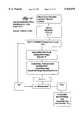
- FIG. 3is a somewhat diagrammatic view of the mapping probe shown in FIGS. 1 and 2 deployed in the left ventricle of the heart and electrically coupled to a process controller that includes a contact sensing module that embodies the features of the invention;
- FIG. 4is a schematic view of a preferred implementation of a contact sensing module that embodies the features of the invention by sensing electrical contact with the myocardium using pacing signals;
- FIGS. 5 and 6are schematic views of a switching device used in association with the contact sensing module shown in FIG. 4;
- FIG. 7is a flow chart showing the operation of the contact sensing module shown in FIG. 4 in Mode 1;
- FIG. 8is a flow chart showing the operation of the contact sensing module shown in FIG. 4 in Mode 2;
- FIG. 9is a schematic view of an alternative implementation of a contact sensing module that embodies the features of the invention by sensing electrical contact with the myocardium using tissue impedance measurements;
- FIG. 10is an enlarged perspective view of a part of the multiple electrode assembly usable in association with the contact sensing module shown in FIG. 9;
- FIG. 11is a flow chart showing the operation of the contact sensing module shown in FIG. 9, being used to sense individual electrode contact by tissue impedance measurements;
- FIG. 12is a flow chart showing further operation of the contact sensing module shown in FIG. 9, being used to assess composite contact of the multiple electrode structure by tissue impedance measurements;
- FIG. 13shows in somewhat diagrammatic form an alternative embodiment of a collapsible endocardial multiple electrode structure deployed in the left ventricle, being shown in a partially collapsed condition for urging electrical contact mostly with the blood pool;
- FIG. 14shows in somewhat diagrammatic form the alternative embodiment shown in FIG. 13, with the multiple electrode structure in an expanded condition for urging electrical contact mostly with the myocardium;
- FIG. 15is a flow chart showing the operation of a contact sensing module usable in association with the multiple electrode structure shown in FIGS. 13 and 14 with the structure in its partially collapsed condition for sensing blood path impedance;
- FIG. 16is a flow chart showing the operation of a contact sensing module usable in association with the multiple electrode structure shown in FIGS. 13 and 14 with the structure in its expanded condition for sensing tissue path impedance;
- FIG. 17is a flow chart showing the operation of a contact sensing module usable in association with the multiple electrode structure shown in FIGS. 13 and 14 comparing sensed tissue path impedance and sensed blood path impedance to derive contact-indicating signals.
- FIG. 1shows an endocardial mapping probe 10.
- the probe 10comprises a flexible catheter tube 12 with a proximal end 14 and a distal end 16.
- the proximal end 14carries an attached handle 18.
- the distal end 16carries a multiple electrode support assembly 20.
- the multiple electrode support assembly 20comprises an array of flexible spline elements 22 assembled to form a three dimensional structure.
- the far ends of the spline elements 22radiate from a distal hub 24.
- the near ends of the spline elements 22are affixed to a base 26, which the distal end 16 of the catheter tube 12 carries.
- the spline elements 22comprise thin, rectilinear strips of resilient metal or plastic material. Still, other cross sectional configurations can be used.
- the support assembly 20retains the spline elements 22 in a circumferentially spaced array.
- the arraytakes the shape of a three dimensional basket structure.
- the resulting structurecan assume other shapes.
- the spline elements 22carry an array of electrodes 38.
- Signal wires (not shown) electrically coupled to the electrodespass along the guide tube 12 and connect to connectors 17 carried outside the handle 18.
- the probe 10includes an outer sheath 40 carried about the catheter tube 12.
- the sheath 40has an inner diameter that is greater than the outer diameter of the catheter tube 12.
- the sheath 40slides along the catheter tube 12 (as the arrows in FIG. 2 show).
- FIG. 2shows, forward movement advances the slidable sheath 40 over the support assembly 20.
- the slidable sheath 40compresses and collapses the support assembly 20 for introduction through a vein or artery to the intended treatment site within the body.
- FIG. 1shows, rearward movement retracts the slidable sheath 40 away from the support assembly 20. This removes the compression force.
- the freed support assembly 20opens and assumes its three dimensional shape inside a heart chamber.
- the electrode support assembly 20can be assembled in different ways. Representative support assemblies are shown in co-pending U.S. patent application Ser. No. 08/206,414, filed Mar. 4, 1994, entitled “Multiple Electrode Support Structures,” which is incorporated herein by reference.
- FIG. 3shows the support assembly 20 deployed and ready for use inside a chamber 30 in the human heart.
- FIG. 3generally shows the support assembly 20 deployed in the left ventricle of the heart.
- the assembly 20can be deployed in other regions of the heart, too.
- the heart shown in the Figuresis not anatomically accurate.
- the Figuresshow the heart in diagrammatic form to demonstrate the features of the invention.
- FIG. 3shows, when deployed within the heart, the circumferentially spaced splines 22 make contact with circumferentially spaced regions of the endocardium.
- the connectors 17plug into a processing system 32.
- the system 32includes an on board signal processing module 34 that receives and processes diagnostic signals from the multiple electrodes 38 on the assembly 20.
- the output of the module 34helps the physician in identifying appropriate ablation sites within the heart.
- the type of signals that the module 34 receives and processescan vary, according to the choice of the physician.
- the physiciancan condition the module 34 to take multiple, sequential measurements of the transmission of electrical current by heart tissue to obtain tissue resistivity measurements.
- tissue resistivity signalsto identify appropriate ablation sites.
- the processing of tissue resistivity signals to identify appropriate ablation sitesis disclosed in co-pending U.S. patent application Ser. No. 08/197,236, filed Jan. 28, 1994, and entitled "Systems and Methods for Matching Electrical Characteristics and Propagation Velocities in Cardiac Tissue to Locate Potential Ablation Sites.”
- the physiciancan condition the module 34 to acquire and process electrograms in a conventional fashion.
- the module 34processes the electrogram information to map the conduction of electrical impulses in the myocardium.
- the physiciancan condition one or more of the electrodes 38 to emit a therapeutic signal into the myocardium.
- the physiciancan condition selected electrodes 38 to emit radio-frequency energy to ablate myocardial tissue.
- a separate ablation probe(not shown) can be deployed for this purpose.
- the support assembly 20should be oriented in the heart chamber 30 to hold all or substantially all electrodes 38 in electrical contact the myocardium.
- the controller 32includes a tissue contact sensing module 36.
- the contact sensing module 36evaluates electrical contact between the myocardium and the multiple electrode array inside the heart.
- the contact sensing module 36electrically senses electrical contact between the myocardium and at least one electrode 38 on spaced apart spline elements 22.
- the module 36generates a unitary contact-indicating output for the energy emitting electrodes 38.
- the unitary outputindicates the presence or absence of the electrical contact between a particular electrode and the myocardium.
- the module 36also correlates the electrode-specific unitary contact-indicating outputs to generate a compound contact-indicating output.
- the compound outputindicates the aggregate electrical contact between the myocardium and the multiple electrode array.
- the module 36electrically senses electrical contact by emitting from one or more of the electrodes 38 an electrical signal that activates the myocardium. In this embodiment, the module 36 ascertains electrical contact by detecting electrograms.
- the module 36electrically senses electrical contact by emitting from one or more of the electrodes 38 an electrical signal that does not activate the myocardium. In this arrangement, the module 36 ascertains electrical contact by measuring tissue impedance.
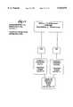
- FIGS. 4 to 6show a preferred implementation of the contact sensing module (designated 36(1)) and the associated processing system 32.
- the module 36(1)generates pacing signals to evaluate the quality of electrical contact between the electrodes 38 and the myocardium.
- This sensing informationis preferably obtained by pacing at the end of diastole, at the stage of the cardiac cycle when the heart is at its maximum relaxation.
- the processing system 32includes a host central processing unit (CPU) 42 (as FIG. 3 also shows).
- the CPU 42communicates with a mass storage device 44 and an extended static RAM block 46.
- a user interactive interface 48also communicates with the CPU 42.
- the interactive user interface 48includes an input device 50 (for example, a key board or mouse) and an output display device 52 (for example, a graphics display monitor or CRT).
- an input device 50for example, a key board or mouse
- an output display device 52for example, a graphics display monitor or CRT.
- the CPU 42communicates with both the signal processing module 34 and the contact sensing module 36(1).
- the CPU 42coordinates the control functions for the modules 34 and 36(1).
- the contact sensing module 36(1)includes a controller interface 54 coupled to the host processor 42.
- the controller interface 54is also coupled to a pulse generator 56 and an output stage 58.
- the output stage 58is electrically coupled by supply path 60 and return path 62 to a switching element 64.
- the configuration of the switching element 64can vary.
- FIG. 5diagrammatically shows one preferred arrangement.
- FIG. 5shows for illustration purposes a spline 22 with seven adjacent electrodes 38, designated E1 to E7.
- Each electrode E1 to E7is electrically coupled to its own signal wire, designated W1 to W7.
- An indifferent electrode, designated EI in FIG. 5,is also electrically coupled to its own signal wire WI.
- the indifferent electrode EIis preferably an electrode in the blood pool.
- the indifferent electrode EIcan be formed by other means. For example, it can also be a conventional patch electrode attached on the outside of the patient's body.
- the switching element 64includes an electronic switch S M and electronic switches S E1 to S E7 that electrically couple the pacing output stage 58 to the signal wires W1 to W7.
- the switch S Mgoverns the overall operating mode of the electrodes E1 to E7 (i.e., unipolar or bipolar).
- the switches S E1 to S E7govern the electrical conduction pattern of the electrodes E1 to E7.
- the switches S M and S E1 to E7are electrically coupled to the output stage 58 of the pulse generator 56 through the lines 60 and 62.
- the supply line 60 of the output stage 58is electrically coupled to the leads L1 of the switches S E1 to E7.
- the return line 62 of the output stage 58is electrically coupled to the center lead L2 of the mode selection switch S M .
- a connector 66electrically couples the leads L3 of the switches S M and S E1 to E7.
- the center leads L2 of the selecting switches S E1 to E7are directly electrically coupled to the signal wires W1 to W7 serving the electrodes E1 to E7, so that one switch S E (N) serves only one electrode E.sub.(N).
- the lead L1 of the switch S Mis directly electrically coupled to the signal wire WI serving the indifferent electrode EI.
- An interface 68electronically sets the switches S M and S E1 to E7 among three positions, designated A, B, and C in FIG. 6.
- Position Aelectrically couples leads L1 and L2 of the associated switch.
- Position Celectrically couples leads L2 and L3 of the associated switch.
- Position Belectrically isolates both leads L1 and L3 from lead L2 of the associated switch.
- Position Bis an electrically OFF position. Positions A and B are electrically ON positions.
- the interface 68electronically inactivates the switching network 64.
- the interface 68electronically configures the switching element for operation in the unipolar mode.
- the center lead L2 of switch S Mis coupled to lead L1, electronically coupling the indifferent electrode EI to the return 62 of the pulse output stage 58. This configures the indifferent electrode EI as a return path for current.
- the interface 68electronically selectively configures each individual electrode E1 to E7 to emit current by sequentially setting the associated switch S E1 to E7 in Position A.
- the selected electrode E1 to E7is so configured, it is electronically coupled to the supply 60 of the pulse output stage 58 and emits current.
- the indifferent electrode EIreceives the current sequentially emitted by the selected electrode E1 to E7.
- the interface 68electronically isolates the indifferent electrode EI from the electrodes E1 to E7. This configures the switching element for operation in the bipolar mode.
- the interface 68can electronically alter the polarity of adjacent electrodes E1 to E7, choosing among current source, current sink, or neither.
- the interface 68electronically configures the associated electrode E1 to E7 to be a current source.
- the interface 68electronically configures the associated electrode E1 to E7 to be a current sink.
- the interface 68electronically turns off the associated electrode E1 to E7.
- the controller interface 54 of the module 36(1)includes control buses 70, 72, and 74.
- Bus 70conveys pulse period control signals to the pulse generator 56.
- Bus 72conveys pulse amplitude control signals to the pulse generator 56.
- Bus 74constitutes the control bus path for the switching element 64 by the means of interface 68.
- the switching element 64When used to pace the heart, the switching element 64 distributes pacing signals generated by the pulse generator 56 to selected basket electrodes 38. The pacing sequence is governed through the interface 54 by the host processor 42.
- the pacing signalWhen emitted by a selected electrode 38 in electrical contact with viable myocardium, the pacing signal depolarizes myocardial tissue at the site of the selected electrode 38. Since the intensity of the electric field generated by the pacing signal decreases with the square of the distance from the emitting electrode 38, the pacing signal will not be effective unless the emitting electrode 38 is very near or in intimate contact with viable myocardium.
- the basket electrodes 38will sense signals as the depolarization front generated by the pacing signal reaches them. These signals are passed back through the switching element 64 and the data acquisition system 75 to the host processor 42 for analysis according to prescribed criteria, which will be described in greater detail later.
- the analysisgenerates contact-indicating output.
- the contact-indicating outputreflects the quality of electrical contact that exists between the myocardium and one or more electrodes 38 on the support assembly 20.
- the module 36(1)operates in two modes. In the first mode, the module 36(1) operates to establish a reliable electrode pacing site by assessing the quality of electrical contact of a single, selected electrode 38 on the support assembly 20 (which will also be called a "unitary contact-indicating output.”). In the second mode, the module 36(1) generates pacing signals in succession from multiple electrode pacing sites to generate the contact-indicating output, which assesses the quality of electrical contact for a composite of all the electrodes on the support assembly 20 (which will also be called a "compound contact-indicating output").
- Mode 1the CPU 42 selects one electrode 38 on the support structure 20. Through the controller interface 54, the CPU 42 causes the pulse generator 56 to generate a pacing signal through the switching element 64 to the selected electrode.
- the pacing signalIn Mode 1, the pacing signal must provide enough voltage or current to the selected electrode to locally stimulate the myocardium. Still, the pacing signal should not be large enough to field stimulate the myocardium at a distance greater than about 2 mm. In the preferred implementation, it is believed that the pacing signal should be about 3 milliamps (3 Volts), with a pulse width of about 0.5 msec.
- the CPU 42By analyzing signals received back through the switching element 64 from at least one electrode on the support assembly 20, the CPU 42 confirms capture; that is, the CPU 42 confirms that a depolarization wavefront emanated from the selected electrode in response to the pacing signal.
- the CPU 42requires all or at least a significant number of electrodes spaced from the selected electrode to sense capture. The greater the number of sensing electrodes used to sense capture, the more reliable the overall output will be.
- the CPU 42Upon sensing capture at the selected electrode, the CPU 42 generates a unitary contact-confirm signal.
- the unitary contact-confirm signalindicates that the selected electrode is in sufficient electrical contact with viable myocardium.
- the CPU 42then automatically switches to the module 36(1) to Mode 2 operation.
- Mode 1multiple pacing signals are sent to the selected electrode and multiple captures are confirmed. This confirms that the module 36(1) is working reliably, and that the electrical stimulus of the pacing signal is large enough to proceed to Mode 2 operation.
- the CPU 42If signals received back through the switching element 64 from at least one electrode on the support assembly 20, do not confirm capture, the CPU 42 generates a unitary contact-contrary signal.
- the unitary contact-contrary signalindicates either (i) the selected electrode is not in sufficient electrical contact with the myocardium, or (ii) that the myocardium that the selected electrode contacts is not viable.
- the unitary contact-contrary signaladvises the physician to relocate the support structure 20 and repeat Mode 1 until a unitary contact-confirm signal is received or he/she decides that the myocardium is not viable.
- the CPU 42Upon entering Mode 2 (see FIG. 8), the CPU 42 causes the controller interface 54 to perform a prescribed pacing cycle. During the pacing cycle, the switching element 64 sends a pacing signal in succession to a selected number of electrodes 38. In the preferred implementation of Mode 2, every electrode on the support structure receives at least one pacing signal during the pacing cycle.
- the pacing ratemust be faster than the baseline heart beat (that is, typically greater than about 70 beats per minute). Preferably, the pacing rate should be at least 20% larger than the baseline heart beat (that is, typically greater than 84 beats per minute).
- a pacing rate of 120 pacing signals per minutecould be selected. Given 60 pacing signals during each pacing cycle (for a support assembly 20 having 60 electrodes), this selected pacing rate would require 30 seconds to complete one pacing cycle.
- the CPU 42registers the number of captures sensed during the pacing cycle. The CPU 42 then evaluates, for each pacing cycle, the number of registered captures against predetermined criteria. Based upon this evaluation, the signal processing system generates the compound contact-indicating output.
- the CPU 42compares, for each pacing cycle, the number of registered captures to the maximum possible number of captures. From this comparison, the signal processing system creates a contact value C VAL , which is computed as follows: ##EQU1##
- C REGis the actual number of registered captures during the pacing cycle
- C MAXis the maximum number of captures possible during the pacing cycle, which corresponds to the number pacing signals generated during the pacing cycle.
- the CPU 42compares the contact value C VAL to a predetermined value C EST to generate the compound contact-indicating output.
- the CPU 42If the contact value C VAL equals or exceeds the predetermined value C EST , the CPU 42 generates through the output 52 a compound contact-confirming signal.
- the compound contact-confirming signalindicates to the physician that the electrodes 38 on the support structure 20 are in sufficient contact with the myocardium to perform a reliable mapping procedure.
- the CPU 42If the contact value C VAL lies below the predetermined value C EST , the CPU 42 generates through the output 52 a compound contact-contrary signal.
- the compound contact-contrary signalindicates to the physician that the electrodes 38 on the support structure 20 are not in sufficient electrical contact with the myocardium to perform a reliable mapping procedure.
- the combined contact-contrary signalsuggests that the physician should relocate the support assembly and repeat Mode 1.
- the module 36(1)allows the physician to generate another pacing cycle to confirm the compound contact-indicating output.
- the predetermined capture value C ESTcan vary according to the physiology of the patient, the structure of the electrode support assembly, and the medical judgement of the physician. For example, C EST for a patient having entirely viable myocardium can be larger than for a patient having damaged heart tissue. The C EST for an assembly 20 having a larger number of electrodes 38 can be smaller than for an assembly 20 having a smaller number of electrodes 38. The medical judgement of one physician may require a larger C EST than another physician.
- pacingis accomplished by operating the electrodes 38 in a uni-polar configuration (that is, by setting switch S M in Position A in FIG. 5).
- an external indifferent electrode EIserves as the return path for the pacing signal.
- the pacingcould be accomplished by operating the electrodes 38 in a bi-polar configuration (that, by setting switch S M in Position C in FIG. 5).
- the pacing signalis generated between spaced apart pairs of electrodes 38 on the support assembly 20 using bipolar pacing techniques.
- one of the electrodes 38 of the bipolar pairis known not to be in electrical contact with viable myocardium. Pacing artifacts are reduced using bipolar pacing.
- the physiciancan cause the process controller 32 to switch to the signal processing module 34 and proceed with the intended mapping process.
- the CPU 42can also specifically identify the electrode sites where capture is sensed and not sensed. By operating the module 36(1) in Mode 2 through successive pacing cycles, the CPU 42 can generate electrode-specific information. For example, the CPU 42 can process historical information obtained during successive pacing cycles to identify locations where capture is consistently not sensed. By generating an output identifying those electrode locations where capture is consistently not sensed, the CPU 42 provides the physician with information that, on a gross scale, indicates where regions of nonviable (i.e., infarcted) myocardium exist.
- FIG. 9shows an alternative implementation of the contact sensing module (designated 36(2)).
- the module 36(2)derives contact-indicating information by measuring tissue impedance.
- the module 36(2)offers the physician the capability of sensing contact throughout the cardiac cycle, systole and diastole.
- the module 36(2)also simplifies sensing contact at each individual electrode site.
- the module 36(2)includes an oscillator 76 that generates a sinusoidal voltage signal.
- An associated interface 78has a bus 80 that controls the frequency of the output voltage signal and a bus 82 that controls the amplitude of the output voltage signal.
- the interface 78is programmed by the host CPU 42, already described.
- the oscillator 76has as an output stage that includes a voltage-to-current converter 84.
- the converter 84converts the sinusoidal voltage signal to current.
- the transmitted currenthas an amplitude of about 0.1 milliamps to 5.0 milliamps.
- the lower range of the current amplitudeis selected to be high enough to overcome the influence of the double layer at the tissue-electrode interface on the impedance measurement.
- the high range of the current amplitudeis selected to avoid the induction of fibrillation.
- the currenthas a frequency in a range of about 5 to 50 kHz.
- the rangeis selected to avoid the induction of fibrillation, as well as provide contrast between infarcted tissue and healthy tissue.
- the output of the converter 84can comprise a constant current with a constant frequency within the above range.
- the interface 78can control the modulation of the frequency of the current signal within the prescribed range.
- the current output of the module 36(2)is supplied to the basket electrodes 38 via supply path 86 through the switching element 64, already described and shown in FIG. 5.
- the interface 78electronically configures the switching element 64 to direct current in succession to selected basket electrodes 38 through their associated signal wires in a unipolar mode (that is, with switch S M in Position A).
- the current return path 88 to the switch element 64is provided by the indifferent electrode EI attached to the patient.
- Line 90constitutes the control bus for the switching element 64.
- the module 36(2)includes a data acquisition system 92. While current is emitted by each selected basket electrode 38, the system 92 senses the voltage in the tissue path lying between the selected electrode 38 and the indifferent electrode EI. Based upon the data acquired by the system 92, the host processor 42 computes the impedance of the path (in ohms) lying between the electrodes.
- the measured path impedancecan be directly correlated to electrode contact with tissue.
- a relatively high impedance valueindicates electrical contact with healthy myocardium, while a relatively low impedance value indicates either a lack of electrical contact or the presence of infarcted myocardium in the path.
- the CPU 42analyzes the computed impedance values according to prescribed criteria. Based upon this comparison, the CPU 42 generates a contact-indicating output.
- the contact-indicating outputreflects the amount of electrical contact that exists between the myocardium and one or more electrodes 28 on the support assembly 20.
- the electrodes 38are mounted to each spline 22 to maximize surface contact with endocardial tissue, while at the same time minimizing exposure to the surrounding blood pool. Incidental exposure of the electrodes 38 to blood while in contact with heart tissue introduces an unwanted artifact to tissue impedance measurement, because the resistivity of blood is about three times lower than the resistivity of heart tissue. This artifact can skew the impedance measurement to a lower value, thereby reducing the desired contrast between contact-confirm and contact-contrary signals.
- the electrodes 38are made of platinum or gold plated stainless steel bands affixed to only one side of the rectilinear splines 22. This is the side of the spline 22 that, in use, contacts endocardial tissue. The opposite surface of the splines 22 (which, in use, contacts the blood pool) is free of electrodes.
- One preferred implementation of this embodimentmaintains contact between the support assembly 20 and the myocardium while deriving the impedance values.
- the implementationcomputes tissue path impedance using the following equation: ##EQU2##
- the PathVoltage and PathCurrentare both root mean squared (RMS) values.
- the voltageis measured in succession between each electrode and the indifferent electrode (or between EI and E(n), where n represents the location of the current emitting electrode).
- the impedance computedreflects not only the impedance of the underlying myocardium, but also includes the impedance of the other tissue mass in the path. The computed impedance therefore is not the actual impedance of the myocardium itself. Rather, it provides a relative scale of impedance differences of the myocardium lying in contact with the electrodes.
- the CPU 42compares the computed impedance E VAL for each electrode to a prescribed impedance value E EST .
- the value E ESTshould account for the resistivities of blood and viable myocardium at the frequency of the emitted current.
- blood resistivityis about 150 ohm.cm
- viable myocardium resistivityis about 450 ohm.cm (infarcted myocardium resistivity is about 250 ohm.cm).
- E ESTis about 150 ohms. Other values could be used for other electrode geometries.
- the computed impedance value E VALequals or exceeds the prescribed value E EST , the CPU 42 infers sufficient electrical contact at that electrode site and generates a unitary contact-confirm signal. If the computed impedance value E VAL is less than the prescribed value E EST , the processing system infers a lack of sufficient electrical contact at that electrode site and generates a unitary contact-contrary signal.
- the unitary contact-confirm and contact-contrary signalsare specific to each electrode site.
- the physiciancan use each of these site specific signals to position the support assembly to obtain the best site specific electrical contact.
- the CPU 42provides the physician with an overall assessment of electrode contact for the support assembly.
- the CPU 42assigns a position score value of 1, indicating sufficient electrical contact at that electrode site. If the computed impedance value E VAL is less than the prescribed value E EST , the CPU 42 assigns a position score value of 0, indicating the lack of sufficient electrical contact at that electrode site.
- the CPU 42computes the sum of the position score values obtained ( ⁇ PS). The CPU 42 then compares the position score value sum ⁇ PS to the total number of electrodes sampled ( ⁇ E). From this comparison, the CPU 42 creates a contact value C VAL , which is computed as follows: ##EQU3##
- the CPU 42compares the contact value C VAL to a predetermined value C EST to generate the compound contact-indicating output.
- the CPU 42If the contact value C VAL equals or exceeds the predetermined value C EST , the CPU 42 generates a compound contact-confirming signal.
- the compound contact-confirming signalindicates to the physician that enough electrodes 38 on the support structure 20 are in sufficient electrical contact with the myocardium to perform a reliable mapping procedure.
- the CPU 42If the contact value C VAL lies below the predetermined value C EST , the CPU 42 generates a compound contact-contrary signal.
- the compound contact-contrary signalindicates to the physician that the electrodes 38 on the support structure 20 are not in sufficient contact with the myocardium to perform a reliable mapping procedure.
- the compound contact-contrary signalsuggests that the physician should relocate the support assembly 20.
- the predetermined contact value C ESTcan vary according to the physiology of the patient, the structure of the electrode support assembly 20, and the medical judgement of the physician.
- the module 36(2)allows the physician to generate another cycle to confirm the compound contact-indicating output.
- FIGS. 13 and 14show an alternate embodiment of a multiple electrode assembly 94 whose contact with the myocardium can be electrically determined by differential tissue impedance measurements.
- the assembly 94comprises an array of flexible spline elements 96 assembled to form a three dimensional structure carried on the distal end 16 of the catheter tube 12.
- the spline elements 96 of the assembly 94carry an array of electrodes 98.
- the electrodes 98are mounted to each spline 22 to maximize surface contact with endocardial tissue, while at the same time minimizing exposure to the surrounding blood pool, as FIG. 10 shows.
- the assembly 94includes a center wire 100 to alter the shape of the structure.
- the distal end of the wire 100connects to the hub 102 of the assembly 94.
- the wire 100passes through the catheter tube 12 into the handle 104, where its proximal end attaches to a control lever 106.
- pushing the control lever 106 forwardcauses the wire 100 to straighten the splines elements 96 inward. This causes at least a partially collapse or elongation of the support assembly 94 within the heart chamber 30. This in turn pulls the electrodes 98 away from electrical contact with the myocardium. Instead, the electrodes 98 are mostly exposed to the blood pool in the chamber 30.
- FIG. 14shows, pulling back on the control lever 106 causes the wire to bend the spline elements 96 outward.
- the support assembly 94expands to its intended fully deployed condition, urging the electrodes 94 toward electrical contact with the myocardium.
- the contact sensing module 36(2)is conditioned by the CPU 42 to measure the relative change in impedance values when the support assembly 94 is opened to contact heart tissue (as in FIG. 14) and when the support assembly 94 is partially collapsed to contact blood (as in FIG. 13).
- the CPU 42generates a contact-indicating output based upon the measured change in impedance values.
- the CPU 42prompts the physician to move the control lever 106 forward to urge the electrodes 98 into the blood pool (as FIG. 13 shows). With the support assembly 98 in this condition, the CPU 42 conditions the module 36(2) to transmit an electrical current in succession through all or at least a significant number of electrodes 98, in the manner previously described.
- the CPU 42computes the impedance, which represents blood path impedance BloodPathImp, since most of the electrode 98 are exposed to the blood pool. BloodPathImp is calculated as follows: ##EQU4##
- the BloodPathVoltage and BloodPathCurrentare both root mean squared (RMS) values.
- the voltageis measured in succession between each electrode and the indifferent electrode (or between EI and E(n), where n represents the location of the current emitting electrode).
- the CPU 42then prompts the physician to move the control lever 106 rearward to urge the electrodes 98 into electrical contact with the myocardium (as FIG. 14 shows). With the support assembly 98 in this condition, the CPU 42 conditions the module 36(2) to again transmit an electrical current in succession through the same electrodes that emitted current when the support assembly 94 was collapsed in the blood pool. The CPU 42 computes impedance, which this time represents tissue path impedance TissuePathImp.
- the CPU 42computes TissuePathImp using the following equation: ##EQU5##
- TissuePathVoltage and TissuePathCurrentare both root mean squared (RMS) values.
- the voltageis measured in succession between each electrode and the indifferent electrode (or between EI and E(n), where n represents the location of the current emitting electrode).
- the CPU 42compares the derived TissuePathImpedance for each electrode with the derived BloodPathImpedance for that electrode.
- the processing systemderives the change in the impedance ( ⁇ IMP), as follows: ##EQU6##
- the CPU 42For each electrode 98 that emitted current, the CPU 42 compares ⁇ IMP to a prescribed difference value ⁇ EST. If ⁇ IMP equals or exceeds ⁇ EST, the CPU 42 infers sufficient electrical contact between the electrode and the myocardium. In this circumstance, the CPU 42 generates a unitary contact-confirm signal. If ⁇ IMP is less than ⁇ EST, the CPU 42 infers that sufficient electrical contact does not exist. In this circumstance, the CPU 42 generates a unitary contact-contrary signal.
- the unitary contact-confirm and contact-contrary signals in this implementationare also specific to each electrode. The physician can use each of these site specific signals to position the support assembly to obtain the best site specific electrical contact.
- the CPU 42can provide the physician with an overall assessment of electrode contact for the support assembly 98. In this implementation (see FIG. 17), if ⁇ IMP equal or exceeds ⁇ EST, the CPU 42 assigns a position score value of 1, indicating sufficient electrical contact at that electrode site. If ⁇ IMP is less than ⁇ EST, the CPU 42 assigns a position score value of 0, indicating the lack of sufficient electrical contact at that electrode site.
- the CPU 42then computes the sum of the position score values obtained ( ⁇ PS), as before described and as shown in FIG. 12. Also as before described and shown in FIG. 12, the CPU 42 then compares the position score value sum ⁇ PS to the total number of electrodes sampled ( ⁇ E). From this comparison, the signal processing system creates a contact value C VAL , which is compared to the predetermined contact value C EST to generate either a position contrary signal or a position confirm signal, as previously described. As before stated, a realistic value for C EST for most procedures is believed to lie at or above 85.
Landscapes
- Health & Medical Sciences (AREA)
- Life Sciences & Earth Sciences (AREA)
- Medical Informatics (AREA)
- Animal Behavior & Ethology (AREA)
- Pathology (AREA)
- Engineering & Computer Science (AREA)
- Biomedical Technology (AREA)
- Heart & Thoracic Surgery (AREA)
- Physics & Mathematics (AREA)
- Molecular Biology (AREA)
- Surgery (AREA)
- Biophysics (AREA)
- General Health & Medical Sciences (AREA)
- Public Health (AREA)
- Veterinary Medicine (AREA)
- Cardiology (AREA)
- Physiology (AREA)
- Electrotherapy Devices (AREA)
- Measurement And Recording Of Electrical Phenomena And Electrical Characteristics Of The Living Body (AREA)
Abstract
Description
This is a continuation of application Ser. No. 08/790,221 filed on Feb. 3, 1997, now abandoned, which is a divisional of 08/221,347 filed on Mar. 31, 1994 (now U.S. Pat. No. 5,598,848 granted on Feb. 4, 1997).
The invention relates to systems and methods for mapping and ablating the interior regions of the heart for treatment of cardiac conditions.
Physicians make use of catheters today in medical procedures to gain access into interior regions of the body to ablate targeted tissue areas. It is important for the physician to be able to precisely locate the catheter and control its emission of energy within the body during tissue ablation procedures.
The need for precise control over the catheter is especially critical during procedures that ablate myocardial tissue from within the heart. These procedures, called electrophysiological therapy, are used to treat cardiac rhythm disturbances.
During these procedures, a physician steers a catheter through a main vein or artery into the interior region of the heart that is to be treated. The physician then further manipulates a steering mechanism to place the electrode carried on the distal tip of the catheter into direct contact with the endocardial tissue. The physician directs energy from the electrode through myocardial tissue either to an indifferent electrode (in a uni-polar electrode arrangement) or to an adjacent electrode (in a bi-polar electrode arrangement) to ablate the tissue and form a lesion.
Physicians examine the propagation of electrical impulses in heart tissue to locate aberrant conductive pathways and to identify foci, which are ablated. The techniques used to analyze these pathways and locate foci are commonly called "mapping."
Conventional cardiac tissue mapping techniques use multiple electrodes positioned in contact with epicardial heart tissue to obtain multiple electrograms. These conventional mapping techniques require invasive open heart surgical techniques to position the electrodes on the epicardial surface of the heart.
An alternative technique of introducing multiple electrode arrays into the heart through vein or arterial accesses to map myocardial tissue is known. Compared to conventional, open heart mapping techniques, endocardial mapping techniques, being comparatively non-invasive, hold great promise. Multiple electrogram signals obtained from within the heart can be externally processed to detect local electrical events and identify likely foci.
To achieve consistent, reliable foci identification rates, all electrodes in a multiple electrode array should be in intimate, electrical contact with heart tissue. With invasive, open heart techniques, multiple electrode contact on exposed epicardial surfaces can be visually confirmed directly by the physician. However, with comparatively non-invasive endocardial mapping techniques, confirming multiple electrode contact within the beating heart can be problematic.
There is the need to provide simple, yet reliable ways of assuring that the electrodes of an endocardial multiple electrode structure are in intimate, electrical contact with tissue within the heart.
This invention has as its principal objective the realization of safe and efficacious endocardial mapping techniques.
One aspect of the invention provides a system and related method for evaluating electrical contact between the myocardium and at least two spaced apart electrodes in the heart. The system and method generate a first unitary contact-indicating output indicating the presence or absence of electrical contact between the myocardium and one of the electrodes. The system and method also generate a second unitary contact-indicating output indicating the presence or absence of electrical contact between the myocardium and the other electrode.
In a preferred embodiment, the system and method correlate the electrode-specific unitary contact-indicating outputs to generate a compound contact-indicating output. The compound output indicates the aggregate of the electrical contact between the myocardium and multiple electrodes in a multiple electrode array.
In one implementation, the system and method sense electrical contact by emitting through the electrodes an electrical signal that does not activate the myocardium. In a preferred arrangement, the system and method acquire a tissue impedance measurement based upon this emission.
In a preferred implementation, the system and method sense electrical contact by emitting through the electrodes an electrical signal that activates the myocardium, like a pacing pulse. In this implementation, the system and method acquire an electrogram based upon this signal emission.
In a preferred implementation, the system and method evaluate electrical contact for a multiple electrode array that comprises electrodes supported on circumferentially spaced splines. The system and method electrically evaluate electrical contact to obtain a unitary contact-indicating output for at least one electrode on each spline. The system and method also correlate these unitary contact-indications to obtain a compound contact-indication, indicating the aggregate electrical contact between the myocardium and the multiple electrode array.
Another aspect of the invention electrically evaluates electrical contact between the myocardium and an electrode inside the heart by emitting electrical energy into the myocardium through the electrode. The system and method that embody this aspect of the invention detect at least one selected signal resulting from the emission of electrical energy by the electrode. The selected signal varies with electrical contact between the electrode and the myocardium to differentiate between electrical contact and the absence of electrical contact. The system and method process the acquired signal by comparing it to an expected signal. The system and method generate a contact-indicating output for the electrode based upon the comparison. The contact-confirm output indicates the presence of electrical contact between the electrode and the myocardium in the form of a contact-confirm signal, and a contact-contrary output indicates the absence of such contact.
Other features and advantages of the inventions are set forth in the following Description and Drawings, as well as in the appended claims.
FIGS. 1 and 2 are plan views of an endocardial mapping probe having a collapsible multiple electrode structure whose electrical contact with the myocardium can be evaluated using a contact sensing module that embodies the features of the invention;
FIG. 3 is a somewhat diagrammatic view of the mapping probe shown in FIGS. 1 and 2 deployed in the left ventricle of the heart and electrically coupled to a process controller that includes a contact sensing module that embodies the features of the invention;
FIG. 4 is a schematic view of a preferred implementation of a contact sensing module that embodies the features of the invention by sensing electrical contact with the myocardium using pacing signals;
FIGS. 5 and 6 are schematic views of a switching device used in association with the contact sensing module shown in FIG. 4;
FIG. 7 is a flow chart showing the operation of the contact sensing module shown in FIG. 4 inMode 1;
FIG. 8 is a flow chart showing the operation of the contact sensing module shown in FIG. 4 inMode 2;
FIG. 9 is a schematic view of an alternative implementation of a contact sensing module that embodies the features of the invention by sensing electrical contact with the myocardium using tissue impedance measurements;
FIG. 10 is an enlarged perspective view of a part of the multiple electrode assembly usable in association with the contact sensing module shown in FIG. 9;
FIG. 11 is a flow chart showing the operation of the contact sensing module shown in FIG. 9, being used to sense individual electrode contact by tissue impedance measurements;
FIG. 12 is a flow chart showing further operation of the contact sensing module shown in FIG. 9, being used to assess composite contact of the multiple electrode structure by tissue impedance measurements;
FIG. 13 shows in somewhat diagrammatic form an alternative embodiment of a collapsible endocardial multiple electrode structure deployed in the left ventricle, being shown in a partially collapsed condition for urging electrical contact mostly with the blood pool;
FIG. 14 shows in somewhat diagrammatic form the alternative embodiment shown in FIG. 13, with the multiple electrode structure in an expanded condition for urging electrical contact mostly with the myocardium;
FIG. 15 is a flow chart showing the operation of a contact sensing module usable in association with the multiple electrode structure shown in FIGS. 13 and 14 with the structure in its partially collapsed condition for sensing blood path impedance;
FIG. 16 is a flow chart showing the operation of a contact sensing module usable in association with the multiple electrode structure shown in FIGS. 13 and 14 with the structure in its expanded condition for sensing tissue path impedance; and
FIG. 17 is a flow chart showing the operation of a contact sensing module usable in association with the multiple electrode structure shown in FIGS. 13 and 14 comparing sensed tissue path impedance and sensed blood path impedance to derive contact-indicating signals.
The invention may be embodied in several forms without departing from its spirit or essential characteristics. The scope of the invention is defined in the appended claims, rather than in the specific description preceding them. All embodiments that fall within the meaning and range of equivalency of the claims are therefore intended to be embraced by the claims.
FIG. 1 shows anendocardial mapping probe 10. Theprobe 10 comprises aflexible catheter tube 12 with a proximal end 14 and adistal end 16. The proximal end 14 carries an attachedhandle 18. Thedistal end 16 carries a multipleelectrode support assembly 20.
The multipleelectrode support assembly 20 comprises an array offlexible spline elements 22 assembled to form a three dimensional structure. The far ends of thespline elements 22 radiate from adistal hub 24. The near ends of thespline elements 22 are affixed to abase 26, which thedistal end 16 of thecatheter tube 12 carries.
Preferably, thespline elements 22 comprise thin, rectilinear strips of resilient metal or plastic material. Still, other cross sectional configurations can be used.
Thesupport assembly 20 retains thespline elements 22 in a circumferentially spaced array. In the illustrated embodiment, the array takes the shape of a three dimensional basket structure. Of course, the resulting structure can assume other shapes.
Thespline elements 22 carry an array ofelectrodes 38. Signal wires (not shown) electrically coupled to the electrodes pass along theguide tube 12 and connect to connectors 17 carried outside thehandle 18.
In the illustrated and preferred embodiment, theprobe 10 includes anouter sheath 40 carried about thecatheter tube 12. As FIG. 2 best shows, thesheath 40 has an inner diameter that is greater than the outer diameter of thecatheter tube 12. As a result, thesheath 40 slides along the catheter tube 12 (as the arrows in FIG. 2 show).
As FIG. 2 shows, forward movement advances theslidable sheath 40 over thesupport assembly 20. In this position, theslidable sheath 40 compresses and collapses thesupport assembly 20 for introduction through a vein or artery to the intended treatment site within the body.
As FIG. 1 shows, rearward movement retracts theslidable sheath 40 away from thesupport assembly 20. This removes the compression force. The freedsupport assembly 20 opens and assumes its three dimensional shape inside a heart chamber.
Theelectrode support assembly 20 can be assembled in different ways. Representative support assemblies are shown in co-pending U.S. patent application Ser. No. 08/206,414, filed Mar. 4, 1994, entitled "Multiple Electrode Support Structures," which is incorporated herein by reference.
FIG. 3 shows thesupport assembly 20 deployed and ready for use inside achamber 30 in the human heart. FIG. 3 generally shows thesupport assembly 20 deployed in the left ventricle of the heart. Of course, theassembly 20 can be deployed in other regions of the heart, too. It should also be noted that the heart shown in the Figures is not anatomically accurate. The Figures show the heart in diagrammatic form to demonstrate the features of the invention.
As FIG. 3 shows, when deployed within the heart, the circumferentially spacedsplines 22 make contact with circumferentially spaced regions of the endocardium.
As FIG. 3 also shows, the connectors 17 plug into aprocessing system 32. Thesystem 32 includes an on boardsignal processing module 34 that receives and processes diagnostic signals from themultiple electrodes 38 on theassembly 20. The output of themodule 34 helps the physician in identifying appropriate ablation sites within the heart. The type of signals that themodule 34 receives and processes can vary, according to the choice of the physician.
For example, the physician can condition themodule 34 to take multiple, sequential measurements of the transmission of electrical current by heart tissue to obtain tissue resistivity measurements. The processing of tissue resistivity signals to identify appropriate ablation sites is disclosed in co-pending U.S. patent application Ser. No. 08/197,236, filed Jan. 28, 1994, and entitled "Systems and Methods for Matching Electrical Characteristics and Propagation Velocities in Cardiac Tissue to Locate Potential Ablation Sites."
Alternatively, or in conjunction with tissue resistivity measurements, the physician can condition themodule 34 to acquire and process electrograms in a conventional fashion. Themodule 34 processes the electrogram information to map the conduction of electrical impulses in the myocardium.
Furthermore, if desired, the physician can condition one or more of theelectrodes 38 to emit a therapeutic signal into the myocardium. For example, the physician can condition selectedelectrodes 38 to emit radio-frequency energy to ablate myocardial tissue. Alternatively, a separate ablation probe (not shown) can be deployed for this purpose.
Regardless of the particular type of signal that is processed, thesupport assembly 20 should be oriented in theheart chamber 30 to hold all or substantially allelectrodes 38 in electrical contact the myocardium. According to the invention, thecontroller 32 includes a tissuecontact sensing module 36. Thecontact sensing module 36 evaluates electrical contact between the myocardium and the multiple electrode array inside the heart.
As will be described in greater detail later, thecontact sensing module 36 electrically senses electrical contact between the myocardium and at least oneelectrode 38 on spaced apart splineelements 22. Themodule 36 generates a unitary contact-indicating output for theenergy emitting electrodes 38. The unitary output indicates the presence or absence of the electrical contact between a particular electrode and the myocardium.
In the illustrated and preferred embodiment, themodule 36 also correlates the electrode-specific unitary contact-indicating outputs to generate a compound contact-indicating output. The compound output indicates the aggregate electrical contact between the myocardium and the multiple electrode array.
In the preferred embodiment themodule 36 electrically senses electrical contact by emitting from one or more of theelectrodes 38 an electrical signal that activates the myocardium. In this embodiment, themodule 36 ascertains electrical contact by detecting electrograms.
In another embodiment, themodule 36 electrically senses electrical contact by emitting from one or more of theelectrodes 38 an electrical signal that does not activate the myocardium. In this arrangement, themodule 36 ascertains electrical contact by measuring tissue impedance.
I. Pace-Locate Module
FIGS. 4 to 6 show a preferred implementation of the contact sensing module (designated 36(1)) and the associatedprocessing system 32.
In this implementation, the module 36(1) generates pacing signals to evaluate the quality of electrical contact between theelectrodes 38 and the myocardium. This sensing information is preferably obtained by pacing at the end of diastole, at the stage of the cardiac cycle when the heart is at its maximum relaxation.
In this implementation (see FIG. 4), theprocessing system 32 includes a host central processing unit (CPU) 42 (as FIG. 3 also shows). TheCPU 42 communicates with amass storage device 44 and an extendedstatic RAM block 46. A user interactive interface 48 also communicates with theCPU 42.
As FIG. 4 shows, the interactive user interface 48 includes an input device 50 (for example, a key board or mouse) and an output display device 52 (for example, a graphics display monitor or CRT).
TheCPU 42 communicates with both thesignal processing module 34 and the contact sensing module 36(1). TheCPU 42 coordinates the control functions for themodules 34 and 36(1).
In the illustrated and preferred implementation (as FIG. 4 shows), the contact sensing module 36(1) includes a controller interface 54 coupled to thehost processor 42. The controller interface 54 is also coupled to apulse generator 56 and anoutput stage 58.
Theoutput stage 58 is electrically coupled bysupply path 60 and returnpath 62 to a switchingelement 64. The configuration of the switchingelement 64 can vary. FIG. 5 diagrammatically shows one preferred arrangement.
FIG. 5 shows for illustration purposes aspline 22 with sevenadjacent electrodes 38, designated E1 to E7. Each electrode E1 to E7 is electrically coupled to its own signal wire, designated W1 to W7. An indifferent electrode, designated EI in FIG. 5, is also electrically coupled to its own signal wire WI. The indifferent electrode EI is preferably an electrode in the blood pool. However, the indifferent electrode EI can be formed by other means. For example, it can also be a conventional patch electrode attached on the outside of the patient's body.
In this arrangement, the switchingelement 64 includes an electronic switch SM and electronic switches SE1 to SE7 that electrically couple thepacing output stage 58 to the signal wires W1 to W7. The switch SM governs the overall operating mode of the electrodes E1 to E7 (i.e., unipolar or bipolar). The switches SE1 to SE7 govern the electrical conduction pattern of the electrodes E1 to E7.
The switches SM and SE1 to E7 are electrically coupled to theoutput stage 58 of thepulse generator 56 through thelines supply line 60 of theoutput stage 58 is electrically coupled to the leads L1 of the switches SE1 to E7. Thereturn line 62 of theoutput stage 58 is electrically coupled to the center lead L2 of the mode selection switch SM. A connector 66 electrically couples the leads L3 of the switches SM and SE1 to E7.
The center leads L2 of the selecting switches SE1 to E7 are directly electrically coupled to the signal wires W1 to W7 serving the electrodes E1 to E7, so that one switch SE(N) serves only one electrode E.sub.(N).
The lead L1 of the switch SM is directly electrically coupled to the signal wire WI serving the indifferent electrode EI.
An interface 68 electronically sets the switches SM and SE1 to E7 among three positions, designated A, B, and C in FIG. 6.
As FIG. 6 shows, Position A electrically couples leads L1 and L2 of the associated switch. Position C electrically couples leads L2 and L3 of the associated switch. Position B electrically isolates both leads L1 and L3 from lead L2 of the associated switch.
Position B is an electrically OFF position. Positions A and B are electrically ON positions.
By setting switch SM in Position B, the interface 68 electronically inactivates theswitching network 64.
By setting switch SM in Position A, the interface 68 electronically configures the switching element for operation in the unipolar mode. The center lead L2 of switch SM is coupled to lead L1, electronically coupling the indifferent electrode EI to thereturn 62 of thepulse output stage 58. This configures the indifferent electrode EI as a return path for current.
With switch SM set in Position A, the interface 68 electronically selectively configures each individual electrode E1 to E7 to emit current by sequentially setting the associated switch SE1 to E7 in Position A. When the selected electrode E1 to E7 is so configured, it is electronically coupled to thesupply 60 of thepulse output stage 58 and emits current. The indifferent electrode EI receives the current sequentially emitted by the selected electrode E1 to E7.
By setting switch SM in Position C, the interface 68 electronically isolates the indifferent electrode EI from the electrodes E1 to E7. This configures the switching element for operation in the bipolar mode.
With switch SM set in Position C, the interface 68 can electronically alter the polarity of adjacent electrodes E1 to E7, choosing among current source, current sink, or neither.
By setting the selected switch SE1 to E7 in Position A, the interface 68 electronically configures the associated electrode E1 to E7 to be a current source. By setting the selected switch SE1 to E7 in Position C, the interface 68 electronically configures the associated electrode E1 to E7 to be a current sink. By setting the selected switch SE1 to E7 in Position B, the interface 68 electronically turns off the associated electrode E1 to E7.
The controller interface 54 of the module 36(1) includescontrol buses Bus 70 conveys pulse period control signals to thepulse generator 56.Bus 72 conveys pulse amplitude control signals to thepulse generator 56.Bus 74 constitutes the control bus path for the switchingelement 64 by the means of interface 68.
When used to pace the heart, the switchingelement 64 distributes pacing signals generated by thepulse generator 56 to selectedbasket electrodes 38. The pacing sequence is governed through the interface 54 by thehost processor 42.
When emitted by a selectedelectrode 38 in electrical contact with viable myocardium, the pacing signal depolarizes myocardial tissue at the site of the selectedelectrode 38. Since the intensity of the electric field generated by the pacing signal decreases with the square of the distance from the emittingelectrode 38, the pacing signal will not be effective unless the emittingelectrode 38 is very near or in intimate contact with viable myocardium.
Thebasket electrodes 38 will sense signals as the depolarization front generated by the pacing signal reaches them. These signals are passed back through the switchingelement 64 and thedata acquisition system 75 to thehost processor 42 for analysis according to prescribed criteria, which will be described in greater detail later. The analysis generates contact-indicating output. The contact-indicating output reflects the quality of electrical contact that exists between the myocardium and one ormore electrodes 38 on thesupport assembly 20.
In the illustrated and preferred implementation, the module 36(1) operates in two modes. In the first mode, the module 36(1) operates to establish a reliable electrode pacing site by assessing the quality of electrical contact of a single, selectedelectrode 38 on the support assembly 20 (which will also be called a "unitary contact-indicating output."). In the second mode, the module 36(1) generates pacing signals in succession from multiple electrode pacing sites to generate the contact-indicating output, which assesses the quality of electrical contact for a composite of all the electrodes on the support assembly 20 (which will also be called a "compound contact-indicating output").
(i) Mode 1: Establishing Unitary Contact
In Mode 1 (see FIG. 7), theCPU 42 selects oneelectrode 38 on thesupport structure 20. Through the controller interface 54, theCPU 42 causes thepulse generator 56 to generate a pacing signal through the switchingelement 64 to the selected electrode.
InMode 1, the pacing signal must provide enough voltage or current to the selected electrode to locally stimulate the myocardium. Still, the pacing signal should not be large enough to field stimulate the myocardium at a distance greater than about 2 mm. In the preferred implementation, it is believed that the pacing signal should be about 3 milliamps (3 Volts), with a pulse width of about 0.5 msec.
By analyzing signals received back through the switchingelement 64 from at least one electrode on thesupport assembly 20, theCPU 42 confirms capture; that is, theCPU 42 confirms that a depolarization wavefront emanated from the selected electrode in response to the pacing signal. In the preferred implementation, theCPU 42 requires all or at least a significant number of electrodes spaced from the selected electrode to sense capture. The greater the number of sensing electrodes used to sense capture, the more reliable the overall output will be.
Upon sensing capture at the selected electrode, theCPU 42 generates a unitary contact-confirm signal. The unitary contact-confirm signal indicates that the selected electrode is in sufficient electrical contact with viable myocardium. TheCPU 42 then automatically switches to the module 36(1) toMode 2 operation.
In the preferred implementation ofMode 1, multiple pacing signals are sent to the selected electrode and multiple captures are confirmed. This confirms that the module 36(1) is working reliably, and that the electrical stimulus of the pacing signal is large enough to proceed toMode 2 operation.
If signals received back through the switchingelement 64 from at least one electrode on thesupport assembly 20, do not confirm capture, theCPU 42 generates a unitary contact-contrary signal. The unitary contact-contrary signal indicates either (i) the selected electrode is not in sufficient electrical contact with the myocardium, or (ii) that the myocardium that the selected electrode contacts is not viable. The unitary contact-contrary signal advises the physician to relocate thesupport structure 20 andrepeat Mode 1 until a unitary contact-confirm signal is received or he/she decides that the myocardium is not viable.
(ii) Mode 2: Establishing Compound Contact
Upon entering Mode 2 (see FIG. 8), theCPU 42 causes the controller interface 54 to perform a prescribed pacing cycle. During the pacing cycle, the switchingelement 64 sends a pacing signal in succession to a selected number ofelectrodes 38. In the preferred implementation ofMode 2, every electrode on the support structure receives at least one pacing signal during the pacing cycle.
The pacing rate must be faster than the baseline heart beat (that is, typically greater than about 70 beats per minute). Preferably, the pacing rate should be at least 20% larger than the baseline heart beat (that is, typically greater than 84 beats per minute).
For example, a pacing rate of 120 pacing signals per minute could be selected. Given 60 pacing signals during each pacing cycle (for asupport assembly 20 having 60 electrodes), this selected pacing rate would require 30 seconds to complete one pacing cycle.
TheCPU 42 registers the number of captures sensed during the pacing cycle. TheCPU 42 then evaluates, for each pacing cycle, the number of registered captures against predetermined criteria. Based upon this evaluation, the signal processing system generates the compound contact-indicating output.
In the preferred implementation, theCPU 42 compares, for each pacing cycle, the number of registered captures to the maximum possible number of captures. From this comparison, the signal processing system creates a contact value CVAL, which is computed as follows: ##EQU1##
where
CREG is the actual number of registered captures during the pacing cycle, and
CMAX is the maximum number of captures possible during the pacing cycle, which corresponds to the number pacing signals generated during the pacing cycle.
In this implementation, theCPU 42 compares the contact value CVAL to a predetermined value CEST to generate the compound contact-indicating output.
If the contact value CVAL equals or exceeds the predetermined value CEST, theCPU 42 generates through the output 52 a compound contact-confirming signal. The compound contact-confirming signal indicates to the physician that theelectrodes 38 on thesupport structure 20 are in sufficient contact with the myocardium to perform a reliable mapping procedure.
If the contact value CVAL lies below the predetermined value CEST, theCPU 42 generates through the output 52 a compound contact-contrary signal. The compound contact-contrary signal indicates to the physician that theelectrodes 38 on thesupport structure 20 are not in sufficient electrical contact with the myocardium to perform a reliable mapping procedure. The combined contact-contrary signal suggests that the physician should relocate the support assembly andrepeat Mode 1.
In either situation, inMode 2 operation, the module 36(1) allows the physician to generate another pacing cycle to confirm the compound contact-indicating output.
The predetermined capture value CEST can vary according to the physiology of the patient, the structure of the electrode support assembly, and the medical judgement of the physician. For example, CEST for a patient having entirely viable myocardium can be larger than for a patient having damaged heart tissue. The CEST for anassembly 20 having a larger number ofelectrodes 38 can be smaller than for anassembly 20 having a smaller number ofelectrodes 38. The medical judgement of one physician may require a larger CEST than another physician.
Taking these variables into consideration, it is believed that an acceptable CEST lies in the range of about 50 to 100. A realistic target for CEST is believed to lie at or above 85 for most procedures.
In the preferred implementation, pacing is accomplished by operating theelectrodes 38 in a uni-polar configuration (that is, by setting switch SM in Position A in FIG. 5). In this configuration, an external indifferent electrode EI serves as the return path for the pacing signal.
In an alternative implementation, the pacing could be accomplished by operating theelectrodes 38 in a bi-polar configuration (that, by setting switch SM in Position C in FIG. 5). In this configuration, the pacing signal is generated between spaced apart pairs ofelectrodes 38 on thesupport assembly 20 using bipolar pacing techniques. Preferably, one of theelectrodes 38 of the bipolar pair is known not to be in electrical contact with viable myocardium. Pacing artifacts are reduced using bipolar pacing.
Once the module generates a compound contact-confirming signal duringMode 2, the physician can cause theprocess controller 32 to switch to thesignal processing module 34 and proceed with the intended mapping process.
Once a satisfactory compound contact-confirming signal is received, theCPU 42 can also specifically identify the electrode sites where capture is sensed and not sensed. By operating the module 36(1) inMode 2 through successive pacing cycles, theCPU 42 can generate electrode-specific information. For example, theCPU 42 can process historical information obtained during successive pacing cycles to identify locations where capture is consistently not sensed. By generating an output identifying those electrode locations where capture is consistently not sensed, theCPU 42 provides the physician with information that, on a gross scale, indicates where regions of nonviable (i.e., infarcted) myocardium exist.
II. Tissue Impedance-Locate Module
FIG. 9 shows an alternative implementation of the contact sensing module (designated 36(2)). In this embodiment, the module 36(2) derives contact-indicating information by measuring tissue impedance.
The module 36(2) offers the physician the capability of sensing contact throughout the cardiac cycle, systole and diastole. The module 36(2) also simplifies sensing contact at each individual electrode site.
As FIG. 9 shows, the module 36(2) includes an oscillator 76 that generates a sinusoidal voltage signal. An associated interface 78 has abus 80 that controls the frequency of the output voltage signal and abus 82 that controls the amplitude of the output voltage signal. The interface 78, in turn, is programmed by thehost CPU 42, already described.
The oscillator 76 has as an output stage that includes a voltage-to-current converter 84. In conventional fashion, the converter 84 converts the sinusoidal voltage signal to current.
In the illustrated and preferred embodiment, the transmitted current has an amplitude of about 0.1 milliamps to 5.0 milliamps. The lower range of the current amplitude is selected to be high enough to overcome the influence of the double layer at the tissue-electrode interface on the impedance measurement. The high range of the current amplitude is selected to avoid the induction of fibrillation.
The current has a frequency in a range of about 5 to 50 kHz. The range is selected to avoid the induction of fibrillation, as well as provide contrast between infarcted tissue and healthy tissue. The output of the converter 84 can comprise a constant current with a constant frequency within the above range. Alternatively, the interface 78 can control the modulation of the frequency of the current signal within the prescribed range.
The current output of the module 36(2) is supplied to thebasket electrodes 38 viasupply path 86 through the switchingelement 64, already described and shown in FIG. 5. The interface 78 electronically configures the switchingelement 64 to direct current in succession to selectedbasket electrodes 38 through their associated signal wires in a unipolar mode (that is, with switch SM in Position A). When operated in a unipolar mode, thecurrent return path 88 to theswitch element 64 is provided by the indifferent electrode EI attached to the patient.Line 90 constitutes the control bus for the switchingelement 64.
The module 36(2) includes adata acquisition system 92. While current is emitted by each selectedbasket electrode 38, thesystem 92 senses the voltage in the tissue path lying between the selectedelectrode 38 and the indifferent electrode EI. Based upon the data acquired by thesystem 92, thehost processor 42 computes the impedance of the path (in ohms) lying between the electrodes.
The measured path impedance can be directly correlated to electrode contact with tissue. A relatively high impedance value indicates electrical contact with healthy myocardium, while a relatively low impedance value indicates either a lack of electrical contact or the presence of infarcted myocardium in the path.
Preliminary tests indicate that for good contact the impedance with respect to a 40 cm2 patch electrode on the back of the patient is about 200 ohms. For poor contact the impedance is about 125 ohms. Other values can be obtained for different electrode geometries.
TheCPU 42 analyzes the computed impedance values according to prescribed criteria. Based upon this comparison, theCPU 42 generates a contact-indicating output. The contact-indicating output reflects the amount of electrical contact that exists between the myocardium and one ormore electrodes 28 on thesupport assembly 20.
In this implementation (as FIG. 10 shows), theelectrodes 38 are mounted to eachspline 22 to maximize surface contact with endocardial tissue, while at the same time minimizing exposure to the surrounding blood pool. Incidental exposure of theelectrodes 38 to blood while in contact with heart tissue introduces an unwanted artifact to tissue impedance measurement, because the resistivity of blood is about three times lower than the resistivity of heart tissue. This artifact can skew the impedance measurement to a lower value, thereby reducing the desired contrast between contact-confirm and contact-contrary signals.
In the illustrated embodiment, theelectrodes 38 are made of platinum or gold plated stainless steel bands affixed to only one side of therectilinear splines 22. This is the side of thespline 22 that, in use, contacts endocardial tissue. The opposite surface of the splines 22 (which, in use, contacts the blood pool) is free of electrodes.
It is believed that no more than 20% of the electrode surface should be exposed to the blood pool during use. Preferable, less than 5% of the electrode should be so exposed during use.
(i) Determine Absolute Tissue Contact
One preferred implementation of this embodiment (see FIG. 11) maintains contact between thesupport assembly 20 and the myocardium while deriving the impedance values.
The implementation computes tissue path impedance using the following equation: ##EQU2##
The PathVoltage and PathCurrent are both root mean squared (RMS) values.
The voltage is measured in succession between each electrode and the indifferent electrode (or between EI and E(n), where n represents the location of the current emitting electrode). The impedance computed reflects not only the impedance of the underlying myocardium, but also includes the impedance of the other tissue mass in the path. The computed impedance therefore is not the actual impedance of the myocardium itself. Rather, it provides a relative scale of impedance differences of the myocardium lying in contact with the electrodes.
TheCPU 42 compares the computed impedance EVAL for each electrode to a prescribed impedance value EEST.
The value EEST should account for the resistivities of blood and viable myocardium at the frequency of the emitted current. For example, blood resistivity is about 150 ohm.cm, while viable myocardium resistivity is about 450 ohm.cm (infarcted myocardium resistivity is about 250 ohm.cm). If the indifferent electrode EI is an external 40 cm2 patch electrode, EEST is about 150 ohms. Other values could be used for other electrode geometries. If the computed impedance value EVAL equals or exceeds the prescribed value EEST, theCPU 42 infers sufficient electrical contact at that electrode site and generates a unitary contact-confirm signal. If the computed impedance value EVAL is less than the prescribed value EEST, the processing system infers a lack of sufficient electrical contact at that electrode site and generates a unitary contact-contrary signal.
The unitary contact-confirm and contact-contrary signals are specific to each electrode site. The physician can use each of these site specific signals to position the support assembly to obtain the best site specific electrical contact.
Alternatively, or at the same time (see FIG. 12), theCPU 42 provides the physician with an overall assessment of electrode contact for the support assembly. In this implementation, if the computed impedance value EVAL equals or exceeds the prescribed value EEST, theCPU 42 assigns a position score value of 1, indicating sufficient electrical contact at that electrode site. If the computed impedance value EVAL is less than the prescribed value EEST, theCPU 42 assigns a position score value of 0, indicating the lack of sufficient electrical contact at that electrode site.
TheCPU 42 computes the sum of the position score values obtained (ΣPS). TheCPU 42 then compares the position score value sum ΣPS to the total number of electrodes sampled (ΣE). From this comparison, theCPU 42 creates a contact value CVAL, which is computed as follows: ##EQU3##
In this implementation, as with the previously described embodiment, theCPU 42 compares the contact value CVAL to a predetermined value CEST to generate the compound contact-indicating output.
If the contact value CVAL equals or exceeds the predetermined value CEST, theCPU 42 generates a compound contact-confirming signal. The compound contact-confirming signal indicates to the physician thatenough electrodes 38 on thesupport structure 20 are in sufficient electrical contact with the myocardium to perform a reliable mapping procedure.
If the contact value CVAL lies below the predetermined value CEST, theCPU 42 generates a compound contact-contrary signal. The compound contact-contrary signal indicates to the physician that theelectrodes 38 on thesupport structure 20 are not in sufficient contact with the myocardium to perform a reliable mapping procedure. The compound contact-contrary signal suggests that the physician should relocate thesupport assembly 20.
As before stated, the predetermined contact value CEST can vary according to the physiology of the patient, the structure of theelectrode support assembly 20, and the medical judgement of the physician.
For reasons stated above, it is believed that an acceptable CEST lies in the range of about 50 to 100. A realistic target for CEST is believed to lie at or above 85 for most procedures.
In either situation, the module 36(2) allows the physician to generate another cycle to confirm the compound contact-indicating output.
(ii) Comparative Blood/Tissue Impedance
FIGS. 13 and 14 show an alternate embodiment of a multiple electrode assembly 94 whose contact with the myocardium can be electrically determined by differential tissue impedance measurements.
Like theassembly 20 shown in FIG. 1, the assembly 94 comprises an array of flexible spline elements 96 assembled to form a three dimensional structure carried on thedistal end 16 of thecatheter tube 12. Like theassembly 20, the spline elements 96 of the assembly 94 carry an array of electrodes 98. The electrodes 98 are mounted to eachspline 22 to maximize surface contact with endocardial tissue, while at the same time minimizing exposure to the surrounding blood pool, as FIG. 10 shows.
Unlike theassembly 20, which used theouter sheath 40 to collapse thespline elements 22, the assembly 94 includes acenter wire 100 to alter the shape of the structure. The distal end of thewire 100 connects to thehub 102 of the assembly 94. Thewire 100 passes through thecatheter tube 12 into thehandle 104, where its proximal end attaches to acontrol lever 106.
As FIG. 13 shows, pushing thecontrol lever 106 forward causes thewire 100 to straighten the splines elements 96 inward. This causes at least a partially collapse or elongation of the support assembly 94 within theheart chamber 30. This in turn pulls the electrodes 98 away from electrical contact with the myocardium. Instead, the electrodes 98 are mostly exposed to the blood pool in thechamber 30.
As FIG. 14 shows, pulling back on thecontrol lever 106 causes the wire to bend the spline elements 96 outward. The support assembly 94 expands to its intended fully deployed condition, urging the electrodes 94 toward electrical contact with the myocardium.
Used in association with the support assembly 94, the contact sensing module 36(2) is conditioned by theCPU 42 to measure the relative change in impedance values when the support assembly 94 is opened to contact heart tissue (as in FIG. 14) and when the support assembly 94 is partially collapsed to contact blood (as in FIG. 13). TheCPU 42 generates a contact-indicating output based upon the measured change in impedance values.
As FIG. 15 shows, theCPU 42 prompts the physician to move thecontrol lever 106 forward to urge the electrodes 98 into the blood pool (as FIG. 13 shows). With the support assembly 98 in this condition, theCPU 42 conditions the module 36(2) to transmit an electrical current in succession through all or at least a significant number of electrodes 98, in the manner previously described. TheCPU 42 computes the impedance, which represents blood path impedance BloodPathImp, since most of the electrode 98 are exposed to the blood pool. BloodPathImp is calculated as follows: ##EQU4##
The BloodPathVoltage and BloodPathCurrent are both root mean squared (RMS) values.
The voltage is measured in succession between each electrode and the indifferent electrode (or between EI and E(n), where n represents the location of the current emitting electrode).
As FIG. 16 shows, theCPU 42 then prompts the physician to move thecontrol lever 106 rearward to urge the electrodes 98 into electrical contact with the myocardium (as FIG. 14 shows). With the support assembly 98 in this condition, theCPU 42 conditions the module 36(2) to again transmit an electrical current in succession through the same electrodes that emitted current when the support assembly 94 was collapsed in the blood pool. TheCPU 42 computes impedance, which this time represents tissue path impedance TissuePathImp.
TheCPU 42 computes TissuePathImp using the following equation: ##EQU5##
As before, the TissuePathVoltage and TissuePathCurrent are both root mean squared (RMS) values.
As before, the voltage is measured in succession between each electrode and the indifferent electrode (or between EI and E(n), where n represents the location of the current emitting electrode).
As FIG. 17 shows, theCPU 42 compares the derived TissuePathImpedance for each electrode with the derived BloodPathImpedance for that electrode. The processing system derives the change in the impedance (ΔIMP), as follows: ##EQU6##
For each electrode 98 that emitted current, theCPU 42 compares ΔIMP to a prescribed difference value ΔEST. If ΔIMP equals or exceeds ΔEST, theCPU 42 infers sufficient electrical contact between the electrode and the myocardium. In this circumstance, theCPU 42 generates a unitary contact-confirm signal. If ΔIMP is less than ΔEST, theCPU 42 infers that sufficient electrical contact does not exist. In this circumstance, theCPU 42 generates a unitary contact-contrary signal.
The unitary contact-confirm and contact-contrary signals in this implementation are also specific to each electrode. The physician can use each of these site specific signals to position the support assembly to obtain the best site specific electrical contact.
Alternatively, or at the same time, theCPU 42 can provide the physician with an overall assessment of electrode contact for the support assembly 98. In this implementation (see FIG. 17), if ΔIMP equal or exceeds ΔEST, theCPU 42 assigns a position score value of 1, indicating sufficient electrical contact at that electrode site. If ΔIMP is less than ΔEST, theCPU 42 assigns a position score value of 0, indicating the lack of sufficient electrical contact at that electrode site.
TheCPU 42 then computes the sum of the position score values obtained (ΣPS), as before described and as shown in FIG. 12. Also as before described and shown in FIG. 12, theCPU 42 then compares the position score value sum ΣPS to the total number of electrodes sampled (ΣE). From this comparison, the signal processing system creates a contact value CVAL, which is compared to the predetermined contact value CEST to generate either a position contrary signal or a position confirm signal, as previously described. As before stated, a realistic value for CEST for most procedures is believed to lie at or above 85.
The features of the invention are set forth in the following claims.
Claims (10)
1. A system for evaluating electrical contact between the myocardium and an electrode disposed inside the heart, comprising:
an electrode;
an energy generating element coupled to the electrode and configured to produce an electrical signal at a level below that necessary to activate the myocardium, the electrode emitting the electrical signal;
an indifferent electrode adapted to be situated outside the heart and serving as a return path for the electrical signal; and
means employing the electrical signal for sensing unitary electrical contact between the electrode and the myocardium and for generating a unitary contact-indicating output indicating the presence or absence of electrical contact.
2. The system of claim 1, wherein the system senses electrical contact by measuring myocardial tissue impedance.
3. The system of claim 1, wherein the indifferent electrode is an externally applied skin patch.
4. A system for evaluating electrical contact between the myocardium and an electrode disposed inside the heart, comprising:
an electrode;
an energy generating element coupled to the electrode and configured to produce an electrical signal at a level below that necessary to activate the myocardium, the electrode emitting the electrical signal;
an indifferent electrode adapted for internal positioning in the blood pool and serving as a return path for the electrical signal; and
means employing the electrical signal for sensing unitary electrical contact between the electrode and the myocardium and for generating a unitary contact-indicating output indicating the presence or absence of electrical contact.
5. A system for evaluating electrical contact between the myocardium and an electrode array disposed inside the heart, the electrode array comprising first and second electrodes, the system comprising:
a first circuit configured for sensing unitary electrical contact between the first electrode and the myocardium via an indifferent electrode situated outside the heart, the first circuit further configured for generating a first unitary contact-indicating output indicating the presence or absence of electrical contact, and
a second circuit configured for sensing unitary electrical contact between the second electrode and the myocardium via the indifferent electrode, the second circuit further configured for generating a second unitary contact-indicating output indicating the presence or absence of electrical contact
wherein at least one of the first and second circuits senses unitary electrical contact between the respective electrode and myocardium by emitting from the respective electrode an electrical signal at a level below that necessary to activate the myocardium.
6. The system of claim 5, wherein the first and second unitary contact-indicating outputs are correlated to generate a compound contact-indicating output representing the aggregate electrical contact between the myocardium and the first and second electrodes.
7. The system of claim 5, wherein at least one of the first and second circuits senses electrical contact by measuring myocardial tissue impedance.
8. A system for evaluating electrical contact between the myocardium and an internal electrode disposed inside the heart, comprising:
an energy generating element for supplying the internal electrode with an electrical signal at a level below that necessary to activate the myocardium, the internal electrode emitting the electrical signal;
an indifferent electrode adapted to be situated outside the heart and serving as a return path for the electrical signal;
a signal acquisition element electrically coupled to the indifferent electrode for detecting at least one acquired signal resulting from the emission of electrical energy by the internal electrode, the acquired signal varying with the presence or absence of electrical contact between the internal electrode and the myocardium to thereby differentiate between electrical contact and the absence of electrical contact;
a processing element electrically coupled to the signal acquisition element to compare the acquired signal with an expected signal; and
an output element for generating a contact-indicating output indicating the presence or absence of electrical contact between the internal electrode and the myocardium based upon the comparison between the acquired signal and the expected signal.
9. A method for evaluating electrical contact between the myocardium and an internal electrode disposed inside the heart, comprising:
emitting from the internal electrode an electrical signal at a level below that necessary to activate the myocardium;
providing a return path for the electrical signal via an indifferent electrode adapted to be located outside the heart; and
detecting at least one acquired signal resulting form the emission of electrical energy by the internal electrode, the acquired signal varying with the presence or absence of electrical contact between the internal electrode and the myocardium to thereby differentiate between electrical contact and the absence of electrical contact.
10. The method of claim 9, further comprising
comparing the acquired signal with an expected signal; and
generating a contact-indicating output signal indicating the presence or absence of electrical contact between the internal electrode and the myocardium based upon the comparison between the acquired signal and the expected signal.
Priority Applications (1)
| Application Number | Priority Date | Filing Date | Title |
|---|---|---|---|
| US08/925,196US5935079A (en) | 1994-03-31 | 1997-09-08 | Systems and methods for positioning multiple electrode structures in electrical contact with the myocardium |
Applications Claiming Priority (3)
| Application Number | Priority Date | Filing Date | Title |
|---|---|---|---|
| US08/221,347US5598848A (en) | 1994-03-31 | 1994-03-31 | Systems and methods for positioning multiple electrode structures in electrical contact with the myocardium |
| US79022197A | 1997-02-03 | 1997-02-03 | |
| US08/925,196US5935079A (en) | 1994-03-31 | 1997-09-08 | Systems and methods for positioning multiple electrode structures in electrical contact with the myocardium |
Related Parent Applications (1)
| Application Number | Title | Priority Date | Filing Date |
|---|---|---|---|
| US79022197AContinuation | 1994-03-31 | 1997-02-03 |
Publications (1)
| Publication Number | Publication Date |
|---|---|
| US5935079Atrue US5935079A (en) | 1999-08-10 |
Family
ID=22827445
Family Applications (2)
| Application Number | Title | Priority Date | Filing Date |
|---|---|---|---|
| US08/221,347Expired - LifetimeUS5598848A (en) | 1994-03-31 | 1994-03-31 | Systems and methods for positioning multiple electrode structures in electrical contact with the myocardium |
| US08/925,196Expired - LifetimeUS5935079A (en) | 1994-03-31 | 1997-09-08 | Systems and methods for positioning multiple electrode structures in electrical contact with the myocardium |
Family Applications Before (1)
| Application Number | Title | Priority Date | Filing Date |
|---|---|---|---|
| US08/221,347Expired - LifetimeUS5598848A (en) | 1994-03-31 | 1994-03-31 | Systems and methods for positioning multiple electrode structures in electrical contact with the myocardium |
Country Status (1)
| Country | Link |
|---|---|
| US (2) | US5598848A (en) |
Cited By (140)
| Publication number | Priority date | Publication date | Assignee | Title |
|---|---|---|---|---|
| US6064905A (en)* | 1998-06-18 | 2000-05-16 | Cordis Webster, Inc. | Multi-element tip electrode mapping catheter |
| WO2001018835A1 (en)* | 1999-09-08 | 2001-03-15 | Endosonics Corporation | Medical device having precision interconnect |
| US6230050B1 (en)* | 1996-05-15 | 2001-05-08 | The University Court Of The University Of Dundee | Methods and apparatus for the detection of dental caries |
| US6264653B1 (en)* | 1999-09-24 | 2001-07-24 | C. R. Band, Inc. | System and method for gauging the amount of electrode-tissue contact using pulsed radio frequency energy |
| EP1169974A1 (en) | 2000-07-07 | 2002-01-09 | Biosense, Inc. | System and method for detecting electrode-tissue contact |
| EP1169976A1 (en)* | 2000-07-07 | 2002-01-09 | Biosense, Inc. | Multi-electrode catheter, system and method |
| WO2002024063A2 (en) | 2000-09-20 | 2002-03-28 | Medtronic, Inc. | Improved system and method for determining tissue contact of an implantable medical device within a body |
| WO2001074439A3 (en)* | 2000-03-29 | 2002-05-16 | St Jude Medical | Implantable heart stimulator |
| US6408199B1 (en) | 2000-07-07 | 2002-06-18 | Biosense, Inc. | Bipolar mapping of intracardiac potentials with electrode having blood permeable covering |
| US6411852B1 (en) | 1997-04-07 | 2002-06-25 | Broncus Technologies, Inc. | Modification of airways by application of energy |
| US20030181965A1 (en)* | 2002-03-19 | 2003-09-25 | Surx, Inc. | Heating method for tissue contraction |
| US6634363B1 (en) | 1997-04-07 | 2003-10-21 | Broncus Technologies, Inc. | Methods of treating lungs having reversible obstructive pulmonary disease |
| US20040059325A1 (en)* | 2002-09-24 | 2004-03-25 | Scimed Life Systems, Inc. | Electrophysiology electrode having multiple power connections and electrophysiology devices including the same |
| US20040162556A1 (en)* | 2003-02-14 | 2004-08-19 | Scimed Life Systems, Inc. | Power supply and control apparatus and electrophysiology systems including the same |
| US6827714B2 (en) | 2001-03-07 | 2004-12-07 | Scimed Life Systems, Inc. | Internal indifferent electrode device for use with lesion creation apparatus and method of forming lesions using the same |
| US20050171583A1 (en)* | 2004-01-30 | 2005-08-04 | Solarant Medical, Inc. | Heating method for tissue contraction |
| US7027869B2 (en) | 1998-01-07 | 2006-04-11 | Asthmatx, Inc. | Method for treating an asthma attack |
| US20060100610A1 (en)* | 2004-03-05 | 2006-05-11 | Wallace Daniel T | Methods using a robotic catheter system |
| US20070038078A1 (en)* | 2005-07-08 | 2007-02-15 | Daniel Osadchy | Relative impedance measurement |
| US20070156128A1 (en)* | 2005-12-30 | 2007-07-05 | Eduardo Jimenez | System and method for selectively energizing catheter electrodes |
| US20070181139A1 (en)* | 2004-05-28 | 2007-08-09 | Hauck John A | Robotic surgical system with contact sensing feature |
| EP1746950A4 (en)* | 2004-05-17 | 2008-07-16 | Cryocor Inc | Device and method for positioning a catheter tip for creating a cryogenic lesion |
| US7425212B1 (en) | 1998-06-10 | 2008-09-16 | Asthmatx, Inc. | Devices for modification of airways by transfer of energy |
| WO2009036369A1 (en) | 2007-09-14 | 2009-03-19 | Corventis, Inc. | System and methods for wireless body fluid monitoring |
| US7556624B2 (en) | 1997-04-07 | 2009-07-07 | Asthmatx, Inc. | Method of increasing gas exchange of a lung |
| US7837679B2 (en) | 2000-10-17 | 2010-11-23 | Asthmatx, Inc. | Control system and process for application of energy to airway walls and other mediums |
| US7853331B2 (en) | 2004-11-05 | 2010-12-14 | Asthmatx, Inc. | Medical device with procedure improvement features |
| WO2009134605A3 (en)* | 2008-05-01 | 2011-02-17 | Magnetecs, Inc. | Method and apparatus for creating a high resolution map of the electrical and mechanical properties of the heart |
| US7921855B2 (en) | 1998-01-07 | 2011-04-12 | Asthmatx, Inc. | Method for treating an asthma attack |
| US7931647B2 (en) | 2006-10-20 | 2011-04-26 | Asthmatx, Inc. | Method of delivering energy to a lung airway using markers |
| US7937148B2 (en) | 2005-10-14 | 2011-05-03 | Nanostim, Inc. | Rate responsive leadless cardiac pacemaker |
| US7949407B2 (en) | 2004-11-05 | 2011-05-24 | Asthmatx, Inc. | Energy delivery devices and methods |
| US20110172658A1 (en)* | 2007-11-16 | 2011-07-14 | Kardium Inc. | Medical device for use in bodily lumens, for example an atrium |
| US7992572B2 (en) | 1998-06-10 | 2011-08-09 | Asthmatx, Inc. | Methods of evaluating individuals having reversible obstructive pulmonary disease |
| US20110230896A1 (en)* | 2004-03-05 | 2011-09-22 | Hansen Medical, Inc. | Robotic catheter system |
| US20110230866A1 (en)* | 2010-03-16 | 2011-09-22 | William Brent Benoist | Delivery device for implantable monitor |
| US20110238083A1 (en)* | 2005-07-01 | 2011-09-29 | Hansen Medical, Inc. | Robotic catheter system and methods |
| US8116841B2 (en) | 2007-09-14 | 2012-02-14 | Corventis, Inc. | Adherent device with multiple physiological sensors |
| US8181656B2 (en) | 1998-06-10 | 2012-05-22 | Asthmatx, Inc. | Methods for treating airways |
| US8190238B2 (en) | 2005-12-09 | 2012-05-29 | Hansen Medical, Inc. | Robotic catheter system and methods |
| US8235983B2 (en) | 2007-07-12 | 2012-08-07 | Asthmatx, Inc. | Systems and methods for delivering energy to passageways in a patient |
| US8249686B2 (en) | 2007-09-14 | 2012-08-21 | Corventis, Inc. | Adherent device for sleep disordered breathing |
| US8251070B2 (en) | 2000-03-27 | 2012-08-28 | Asthmatx, Inc. | Methods for treating airways |
| US8257413B2 (en) | 2000-10-17 | 2012-09-04 | Asthmatx, Inc. | Modification of airways by application of energy |
| US8412317B2 (en) | 2008-04-18 | 2013-04-02 | Corventis, Inc. | Method and apparatus to measure bioelectric impedance of patient tissue |
| US8460189B2 (en) | 2007-09-14 | 2013-06-11 | Corventis, Inc. | Adherent cardiac monitor with advanced sensing capabilities |
| US8483831B1 (en) | 2008-02-15 | 2013-07-09 | Holaira, Inc. | System and method for bronchial dilation |
| US8489172B2 (en) | 2008-01-25 | 2013-07-16 | Kardium Inc. | Liposuction system |
| US8527068B2 (en) | 2009-02-02 | 2013-09-03 | Nanostim, Inc. | Leadless cardiac pacemaker with secondary fixation capability |
| US8543205B2 (en) | 2010-10-12 | 2013-09-24 | Nanostim, Inc. | Temperature sensor for a leadless cardiac pacemaker |
| US8615310B2 (en) | 2010-12-13 | 2013-12-24 | Pacesetter, Inc. | Delivery catheter systems and methods |
| US8684925B2 (en) | 2007-09-14 | 2014-04-01 | Corventis, Inc. | Injectable device for physiological monitoring |
| US8718752B2 (en) | 2008-03-12 | 2014-05-06 | Corventis, Inc. | Heart failure decompensation prediction based on cardiac rhythm |
| US8740895B2 (en) | 2009-10-27 | 2014-06-03 | Holaira, Inc. | Delivery devices with coolable energy emitting assemblies |
| US8790259B2 (en) | 2009-10-22 | 2014-07-29 | Corventis, Inc. | Method and apparatus for remote detection and monitoring of functional chronotropic incompetence |
| US8808280B2 (en) | 2008-05-09 | 2014-08-19 | Holaira, Inc. | Systems, assemblies, and methods for treating a bronchial tree |
| US8897868B2 (en) | 2007-09-14 | 2014-11-25 | Medtronic, Inc. | Medical device automatic start-up upon contact to patient tissue |
| US8911439B2 (en) | 2009-11-11 | 2014-12-16 | Holaira, Inc. | Non-invasive and minimally invasive denervation methods and systems for performing the same |
| US8920413B2 (en) | 2004-11-12 | 2014-12-30 | Asthmatx, Inc. | Energy delivery devices and methods |
| US8920411B2 (en)* | 2006-06-28 | 2014-12-30 | Kardium Inc. | Apparatus and method for intra-cardiac mapping and ablation |
| US8940002B2 (en) | 2010-09-30 | 2015-01-27 | Kardium Inc. | Tissue anchor system |
| US8965498B2 (en) | 2010-04-05 | 2015-02-24 | Corventis, Inc. | Method and apparatus for personalized physiologic parameters |
| US9011423B2 (en) | 2012-05-21 | 2015-04-21 | Kardium, Inc. | Systems and methods for selecting, activating, or selecting and activating transducers |
| US9020611B2 (en) | 2010-10-13 | 2015-04-28 | Pacesetter, Inc. | Leadless cardiac pacemaker with anti-unscrewing feature |
| US9060692B2 (en) | 2010-10-12 | 2015-06-23 | Pacesetter, Inc. | Temperature sensor for a leadless cardiac pacemaker |
| US9072511B2 (en) | 2011-03-25 | 2015-07-07 | Kardium Inc. | Medical kit for constricting tissue or a bodily orifice, for example, a mitral valve |
| US9119633B2 (en) | 2006-06-28 | 2015-09-01 | Kardium Inc. | Apparatus and method for intra-cardiac mapping and ablation |
| US9126032B2 (en) | 2010-12-13 | 2015-09-08 | Pacesetter, Inc. | Pacemaker retrieval systems and methods |
| US9149328B2 (en) | 2009-11-11 | 2015-10-06 | Holaira, Inc. | Systems, apparatuses, and methods for treating tissue and controlling stenosis |
| US9168383B2 (en) | 2005-10-14 | 2015-10-27 | Pacesetter, Inc. | Leadless cardiac pacemaker with conducted communication |
| US9192468B2 (en) | 2006-06-28 | 2015-11-24 | Kardium Inc. | Method for anchoring a mitral valve |
| US9198592B2 (en) | 2012-05-21 | 2015-12-01 | Kardium Inc. | Systems and methods for activating transducers |
| US9204964B2 (en) | 2009-10-01 | 2015-12-08 | Kardium Inc. | Medical device, kit and method for constricting tissue or a bodily orifice, for example, a mitral valve |
| US20150374427A1 (en)* | 2013-03-13 | 2015-12-31 | Kardium, Inc. | Detecting improper energy transmission configuration in medical device system |
| US9242102B2 (en) | 2010-12-20 | 2016-01-26 | Pacesetter, Inc. | Leadless pacemaker with radial fixation mechanism |
| US9272132B2 (en) | 2012-11-02 | 2016-03-01 | Boston Scientific Scimed, Inc. | Medical device for treating airways and related methods of use |
| US9283374B2 (en) | 2012-11-05 | 2016-03-15 | Boston Scientific Scimed, Inc. | Devices and methods for delivering energy to body lumens |
| US9314306B2 (en) | 2010-09-17 | 2016-04-19 | Hansen Medical, Inc. | Systems and methods for manipulating an elongate member |
| US9326822B2 (en) | 2013-03-14 | 2016-05-03 | Hansen Medical, Inc. | Active drives for robotic catheter manipulators |
| US9339618B2 (en) | 2003-05-13 | 2016-05-17 | Holaira, Inc. | Method and apparatus for controlling narrowing of at least one airway |
| US9358076B2 (en) | 2011-01-20 | 2016-06-07 | Hansen Medical, Inc. | System and method for endoluminal and translumenal therapy |
| US9398933B2 (en) | 2012-12-27 | 2016-07-26 | Holaira, Inc. | Methods for improving drug efficacy including a combination of drug administration and nerve modulation |
| US9408669B2 (en) | 2013-03-15 | 2016-08-09 | Hansen Medical, Inc. | Active drive mechanism with finite range of motion |
| US9411936B2 (en) | 2007-09-14 | 2016-08-09 | Medtronic Monitoring, Inc. | Dynamic pairing of patients to data collection gateways |
| US9451897B2 (en) | 2009-12-14 | 2016-09-27 | Medtronic Monitoring, Inc. | Body adherent patch with electronics for physiologic monitoring |
| US9452016B2 (en) | 2011-01-21 | 2016-09-27 | Kardium Inc. | Catheter system |
| US9480525B2 (en) | 2011-01-21 | 2016-11-01 | Kardium, Inc. | High-density electrode-based medical device system |
| US9492228B2 (en) | 2011-01-21 | 2016-11-15 | Kardium Inc. | Enhanced medical device for use in bodily cavities, for example an atrium |
| US20160331267A1 (en)* | 2012-12-20 | 2016-11-17 | Boston Scientific Scimed Inc. | Real-time feedback for electrode contact during mapping |
| US9511236B2 (en) | 2011-11-04 | 2016-12-06 | Pacesetter, Inc. | Leadless cardiac pacemaker with integral battery and redundant welds |
| US9510905B2 (en) | 2014-11-19 | 2016-12-06 | Advanced Cardiac Therapeutics, Inc. | Systems and methods for high-resolution mapping of tissue |
| US9517103B2 (en) | 2014-11-19 | 2016-12-13 | Advanced Cardiac Therapeutics, Inc. | Medical instruments with multiple temperature sensors |
| US9532725B2 (en) | 2014-03-07 | 2017-01-03 | Boston Scientific Scimed Inc. | Medical devices for mapping cardiac tissue |
| USD777926S1 (en) | 2012-01-20 | 2017-01-31 | Kardium Inc. | Intra-cardiac procedure device |
| USD777925S1 (en) | 2012-01-20 | 2017-01-31 | Kardium Inc. | Intra-cardiac procedure device |
| US9572557B2 (en) | 2006-02-21 | 2017-02-21 | Kardium Inc. | Method and device for closing holes in tissue |
| US9592086B2 (en) | 2012-07-24 | 2017-03-14 | Boston Scientific Scimed, Inc. | Electrodes for tissue treatment |
| US9636164B2 (en) | 2015-03-25 | 2017-05-02 | Advanced Cardiac Therapeutics, Inc. | Contact sensing systems and methods |
| US9687167B2 (en) | 2014-03-11 | 2017-06-27 | Boston Scientific Scimed, Inc. | Medical devices for mapping cardiac tissue |
| US9730600B2 (en) | 2013-10-31 | 2017-08-15 | Boston Scientific Scimed, Inc. | Medical device for high resolution mapping using localized matching |
| US9744038B2 (en) | 2008-05-13 | 2017-08-29 | Kardium Inc. | Medical device for constricting tissue or a bodily orifice, for example a mitral valve |
| CN107184270A (en)* | 2017-05-05 | 2017-09-22 | 上海安臻医疗科技有限公司 | A kind of adherent feedback method of radio frequency ablation system |
| US9770293B2 (en) | 2012-06-04 | 2017-09-26 | Boston Scientific Scimed, Inc. | Systems and methods for treating tissue of a passageway within a body |
| US9802054B2 (en) | 2012-08-01 | 2017-10-31 | Pacesetter, Inc. | Biostimulator circuit with flying cell |
| US9814618B2 (en) | 2013-06-06 | 2017-11-14 | Boston Scientific Scimed, Inc. | Devices for delivering energy and related methods of use |
| US9993178B2 (en) | 2016-03-15 | 2018-06-12 | Epix Therapeutics, Inc. | Methods of determining catheter orientation |
| US10028783B2 (en) | 2006-06-28 | 2018-07-24 | Kardium Inc. | Apparatus and method for intra-cardiac mapping and ablation |
| US10046140B2 (en) | 2014-04-21 | 2018-08-14 | Hansen Medical, Inc. | Devices, systems, and methods for controlling active drive systems |
| US10076258B2 (en) | 2013-11-01 | 2018-09-18 | Boston Scientific Scimed, Inc. | Cardiac mapping using latency interpolation |
| US10166062B2 (en) | 2014-11-19 | 2019-01-01 | Epix Therapeutics, Inc. | High-resolution mapping of tissue with pacing |
| US10363103B2 (en) | 2009-04-29 | 2019-07-30 | Auris Health, Inc. | Flexible and steerable elongate instruments with shape control and support elements |
| US10368936B2 (en) | 2014-11-17 | 2019-08-06 | Kardium Inc. | Systems and methods for selecting, activating, or selecting and activating transducers |
| US10463439B2 (en) | 2016-08-26 | 2019-11-05 | Auris Health, Inc. | Steerable catheter with shaft load distributions |
| US10478247B2 (en) | 2013-08-09 | 2019-11-19 | Boston Scientific Scimed, Inc. | Expandable catheter and related methods of manufacture and use |
| US10524867B2 (en) | 2013-03-15 | 2020-01-07 | Auris Health, Inc. | Active drive mechanism for simultaneous rotation and translation |
| US10556092B2 (en) | 2013-03-14 | 2020-02-11 | Auris Health, Inc. | Active drives for robotic catheter manipulators |
| US10583271B2 (en) | 2012-11-28 | 2020-03-10 | Auris Health, Inc. | Method of anchoring pullwire directly articulatable region in catheter |
| US10667720B2 (en) | 2011-07-29 | 2020-06-02 | Auris Health, Inc. | Apparatus and methods for fiber integration and registration |
| US10722184B2 (en) | 2014-11-17 | 2020-07-28 | Kardium Inc. | Systems and methods for selecting, activating, or selecting and activating transducers |
| US10827977B2 (en) | 2012-05-21 | 2020-11-10 | Kardium Inc. | Systems and methods for activating transducers |
| EP3741298A2 (en) | 2019-05-23 | 2020-11-25 | Biosense Webster (Israel) Ltd | Indicating electrode contact |
| US10888373B2 (en) | 2017-04-27 | 2021-01-12 | Epix Therapeutics, Inc. | Contact assessment between an ablation catheter and tissue |
| EP3791816A2 (en) | 2019-09-12 | 2021-03-17 | Biosense Webster (Israel) Ltd | Balloon catheter with force sensor |
| WO2021113862A1 (en) | 2019-12-04 | 2021-06-10 | Biosense Webster (Israel) Ltd. | Catheter contact force sensor |
| US11033392B2 (en) | 2006-08-02 | 2021-06-15 | Kardium Inc. | System for improving diastolic dysfunction |
| US11241559B2 (en) | 2016-08-29 | 2022-02-08 | Auris Health, Inc. | Active drive for guidewire manipulation |
| US11259867B2 (en) | 2011-01-21 | 2022-03-01 | Kardium Inc. | High-density electrode-based medical device system |
| EP4014847A1 (en) | 2020-12-16 | 2022-06-22 | Biosense Webster (Israel) Ltd | Accurate tissue proximity |
| EP4018953A2 (en) | 2020-12-22 | 2022-06-29 | Biosense Webster (Israel) Ltd | Distal end assembly guidance |
| US11389232B2 (en) | 2006-06-28 | 2022-07-19 | Kardium Inc. | Apparatus and method for intra-cardiac mapping and ablation |
| US20220370145A1 (en)* | 2021-05-24 | 2022-11-24 | Biosense Webster (Israel) Ltd. | Gesture based selection of portion of catheter |
| EP4115828A1 (en) | 2021-07-06 | 2023-01-11 | Biosense Webster (Israel) Ltd | Contact assessment for balloon catheter |
| EP4122413A1 (en) | 2021-07-23 | 2023-01-25 | Biosense Webster (Israel) Ltd | Accurate tissue proximity |
| EP4183342A1 (en) | 2021-11-22 | 2023-05-24 | Biosense Webster (Israel) Ltd | Mapping system with realtime electrogram overlay |
| EP4205653A1 (en) | 2021-12-30 | 2023-07-05 | Biosense Webster (Israel) Ltd. | Intuitive mapping system |
| US11786300B2 (en) | 2021-04-07 | 2023-10-17 | Btl Medical Technologies S.R.O. | Pulsed field ablation device and method |
| US11896298B2 (en) | 2021-07-06 | 2024-02-13 | Btl Medical Development A.S. | Pulsed field ablation device and method |
| EP4393389A1 (en) | 2022-12-27 | 2024-07-03 | Biosense Webster (Israel) Ltd. | Systems and methods for mapping tissue contact via triangulation |
| US12076067B2 (en) | 2022-10-05 | 2024-09-03 | Btl Medical Development A.S. | Pulsed field ablation device and method |
| EP4272669A4 (en)* | 2020-12-31 | 2024-11-20 | Hangzhou Broncus Medical Co., Ltd. | Radio frequency operation safety control method, device and radio frequency host |
Families Citing this family (183)
| Publication number | Priority date | Publication date | Assignee | Title |
|---|---|---|---|---|
| US5797903A (en)* | 1996-04-12 | 1998-08-25 | Ep Technologies, Inc. | Tissue heating and ablation systems and methods using porous electrode structures with electrically conductive surfaces |
| US5840076A (en)* | 1996-04-12 | 1998-11-24 | Ep Technologies, Inc. | Tissue heating and ablation systems and methods using electrode structures with distally oriented porous regions |
| ZA948393B (en)* | 1993-11-01 | 1995-06-26 | Polartechnics Ltd | Method and apparatus for tissue type recognition |
| US5598848A (en)* | 1994-03-31 | 1997-02-04 | Ep Technologies, Inc. | Systems and methods for positioning multiple electrode structures in electrical contact with the myocardium |
| CA2213133C (en) | 1995-02-17 | 2003-06-17 | Ep Technologies, Inc. | Systems and methods for making time-sequential measurements of biological events |
| US5879348A (en)* | 1996-04-12 | 1999-03-09 | Ep Technologies, Inc. | Electrode structures formed from flexible, porous, or woven materials |
| WO1997025918A1 (en)* | 1996-01-19 | 1997-07-24 | Ep Technologies, Inc. | Electrode structures formed from flexible, porous, or woven materials |
| US5925038A (en)* | 1996-01-19 | 1999-07-20 | Ep Technologies, Inc. | Expandable-collapsible electrode structures for capacitive coupling to tissue |
| US5868736A (en)* | 1996-04-12 | 1999-02-09 | Ep Technologies, Inc. | Systems and methods to control tissue heating or ablation with porous electrode structures |
| US5891136A (en)* | 1996-01-19 | 1999-04-06 | Ep Technologies, Inc. | Expandable-collapsible mesh electrode structures |
| US6475213B1 (en) | 1996-01-19 | 2002-11-05 | Ep Technologies, Inc. | Method of ablating body tissue |
| US5846239A (en)* | 1996-04-12 | 1998-12-08 | Ep Technologies, Inc. | Tissue heating and ablation systems and methods using segmented porous electrode structures |
| US5871483A (en)* | 1996-01-19 | 1999-02-16 | Ep Technologies, Inc. | Folding electrode structures |
| US5846238A (en)* | 1996-01-19 | 1998-12-08 | Ep Technologies, Inc. | Expandable-collapsible electrode structures with distal end steering or manipulation |
| US5830213A (en)* | 1996-04-12 | 1998-11-03 | Ep Technologies, Inc. | Systems for heating and ablating tissue using multifunctional electrode structures |
| US5961513A (en)* | 1996-01-19 | 1999-10-05 | Ep Technologies, Inc. | Tissue heating and ablation systems and methods using porous electrode structures |
| US5891135A (en)* | 1996-01-19 | 1999-04-06 | Ep Technologies, Inc. | Stem elements for securing tubing and electrical wires to expandable-collapsible electrode structures |
| US5836874A (en)* | 1996-04-08 | 1998-11-17 | Ep Technologies, Inc. | Multi-function electrode structures for electrically analyzing and heating body tissue |
| US6071278A (en)* | 1996-02-28 | 2000-06-06 | Ep Technologies, Inc. | Tissue heating and ablation systems and methods using porous electrode structures with specified electrical resistivities |
| WO1997025917A1 (en)* | 1996-01-19 | 1997-07-24 | Ep Technologies, Inc. | Multi-function electrode structures for electrically analyzing and heating body tissue |
| US5853411A (en)* | 1996-01-19 | 1998-12-29 | Ep Technologies, Inc. | Enhanced electrical connections for electrode structures |
| US6217585B1 (en)* | 1996-08-16 | 2001-04-17 | Converge Medical, Inc. | Mechanical stent and graft delivery system |
| US5820568A (en)* | 1996-10-15 | 1998-10-13 | Cardiac Pathways Corporation | Apparatus and method for aiding in the positioning of a catheter |
| US5782826A (en)* | 1996-11-01 | 1998-07-21 | Ep Technologies, Inc. | System and methods for detecting ancillary tissue near tissue targeted for ablation |
| US5701907A (en)* | 1996-12-16 | 1997-12-30 | Hewlett-Packard Company | Electrocardiographic waveform monitoring method and system |
| US5697378A (en)* | 1996-12-16 | 1997-12-16 | Siemens Medical Systems, Inc. | Method and apparatus for using multiple leads for QRS detection |
| US6088614A (en)* | 1997-03-31 | 2000-07-11 | Boston Scientific Corporation | Tissue characterization to identify an ablation site |
| US5954661A (en)* | 1997-03-31 | 1999-09-21 | Thomas Jefferson University | Tissue characterization and treatment using pacing |
| US6014579A (en)* | 1997-07-21 | 2000-01-11 | Cardiac Pathways Corp. | Endocardial mapping catheter with movable electrode |
| US6778853B1 (en)* | 1997-12-17 | 2004-08-17 | University Of South Florida | Electroporation device |
| WO1999052588A1 (en)* | 1998-04-14 | 1999-10-21 | Koninklijke Philips Electronics N.V. | Electro-stimulation apparatus |
| US6110100A (en)* | 1998-04-22 | 2000-08-29 | Scimed Life Systems, Inc. | System for stress relieving the heart muscle and for controlling heart function |
| US6035226A (en)* | 1998-05-22 | 2000-03-07 | Scimed Life Systems, Inc. | Systems and methods for assessing stability of an operative instrument inside a body region |
| US6129669A (en)* | 1998-05-22 | 2000-10-10 | Scimed Life Systems, Inc. | Systems and methods for assessing stability of an ablation electrode in contact with heart tissue |
| US20070123958A1 (en)* | 1998-06-10 | 2007-05-31 | Asthmatx, Inc. | Apparatus for treating airways in the lung |
| US7194294B2 (en)* | 1999-01-06 | 2007-03-20 | Scimed Life Systems, Inc. | Multi-functional medical catheter and methods of use |
| US6206831B1 (en) | 1999-01-06 | 2001-03-27 | Scimed Life Systems, Inc. | Ultrasound-guided ablation catheter and methods of use |
| US6309384B1 (en) | 1999-02-01 | 2001-10-30 | Adiana, Inc. | Method and apparatus for tubal occlusion |
| US6391024B1 (en)* | 1999-06-17 | 2002-05-21 | Cardiac Pacemakers, Inc. | RF ablation apparatus and method having electrode/tissue contact assessment scheme and electrocardiogram filtering |
| US8974446B2 (en) | 2001-10-11 | 2015-03-10 | St. Jude Medical, Inc. | Ultrasound ablation apparatus with discrete staggered ablation zones |
| US6780182B2 (en)* | 2002-05-23 | 2004-08-24 | Adiana, Inc. | Catheter placement detection system and operator interface |
| US20040082947A1 (en)* | 2002-10-25 | 2004-04-29 | The Regents Of The University Of Michigan | Ablation catheters |
| US20050033137A1 (en)* | 2002-10-25 | 2005-02-10 | The Regents Of The University Of Michigan | Ablation catheters and methods for their use |
| US20060089637A1 (en)* | 2004-10-14 | 2006-04-27 | Werneth Randell L | Ablation catheter |
| US9101386B2 (en) | 2004-10-15 | 2015-08-11 | Amendia, Inc. | Devices and methods for treating tissue |
| US7963915B2 (en)* | 2004-10-15 | 2011-06-21 | Baxano, Inc. | Devices and methods for tissue access |
| US7738969B2 (en)* | 2004-10-15 | 2010-06-15 | Baxano, Inc. | Devices and methods for selective surgical removal of tissue |
| US7938830B2 (en)* | 2004-10-15 | 2011-05-10 | Baxano, Inc. | Powered tissue modification devices and methods |
| US7887538B2 (en) | 2005-10-15 | 2011-02-15 | Baxano, Inc. | Methods and apparatus for tissue modification |
| US8221397B2 (en) | 2004-10-15 | 2012-07-17 | Baxano, Inc. | Devices and methods for tissue modification |
| US20090018507A1 (en)* | 2007-07-09 | 2009-01-15 | Baxano, Inc. | Spinal access system and method |
| US20080161809A1 (en)* | 2006-10-03 | 2008-07-03 | Baxano, Inc. | Articulating Tissue Cutting Device |
| US8062300B2 (en)* | 2006-05-04 | 2011-11-22 | Baxano, Inc. | Tissue removal with at least partially flexible devices |
| US20110190772A1 (en) | 2004-10-15 | 2011-08-04 | Vahid Saadat | Powered tissue modification devices and methods |
| US8430881B2 (en) | 2004-10-15 | 2013-04-30 | Baxano, Inc. | Mechanical tissue modification devices and methods |
| US8257356B2 (en)* | 2004-10-15 | 2012-09-04 | Baxano, Inc. | Guidewire exchange systems to treat spinal stenosis |
| US7857813B2 (en) | 2006-08-29 | 2010-12-28 | Baxano, Inc. | Tissue access guidewire system and method |
| US20060122458A1 (en)* | 2004-10-15 | 2006-06-08 | Baxano, Inc. | Devices and methods for tissue access |
| US7578819B2 (en)* | 2005-05-16 | 2009-08-25 | Baxano, Inc. | Spinal access and neural localization |
| US8048080B2 (en) | 2004-10-15 | 2011-11-01 | Baxano, Inc. | Flexible tissue rasp |
| JP5243034B2 (en) | 2004-10-15 | 2013-07-24 | バクサノ,インク. | Tissue removal device |
| US20100331883A1 (en) | 2004-10-15 | 2010-12-30 | Schmitz Gregory P | Access and tissue modification systems and methods |
| US9247952B2 (en) | 2004-10-15 | 2016-02-02 | Amendia, Inc. | Devices and methods for tissue access |
| US8613745B2 (en)* | 2004-10-15 | 2013-12-24 | Baxano Surgical, Inc. | Methods, systems and devices for carpal tunnel release |
| US7959577B2 (en) | 2007-09-06 | 2011-06-14 | Baxano, Inc. | Method, system, and apparatus for neural localization |
| US8617152B2 (en)* | 2004-11-15 | 2013-12-31 | Medtronic Ablation Frontiers Llc | Ablation system with feedback |
| US7429261B2 (en)* | 2004-11-24 | 2008-09-30 | Ablation Frontiers, Inc. | Atrial ablation catheter and method of use |
| US7468062B2 (en)* | 2004-11-24 | 2008-12-23 | Ablation Frontiers, Inc. | Atrial ablation catheter adapted for treatment of septal wall arrhythmogenic foci and method of use |
| EP2759276A1 (en) | 2005-06-20 | 2014-07-30 | Medtronic Ablation Frontiers LLC | Ablation catheter |
| AU2006268238A1 (en)* | 2005-07-11 | 2007-01-18 | Medtronic Ablation Frontiers Llc | Low power tissue ablation system |
| US8657814B2 (en) | 2005-08-22 | 2014-02-25 | Medtronic Ablation Frontiers Llc | User interface for tissue ablation system |
| US8366712B2 (en) | 2005-10-15 | 2013-02-05 | Baxano, Inc. | Multiple pathways for spinal nerve root decompression from a single access point |
| US20080091227A1 (en)* | 2006-08-25 | 2008-04-17 | Baxano, Inc. | Surgical probe and method of making |
| US8092456B2 (en)* | 2005-10-15 | 2012-01-10 | Baxano, Inc. | Multiple pathways for spinal nerve root decompression from a single access point |
| US8062298B2 (en) | 2005-10-15 | 2011-11-22 | Baxano, Inc. | Flexible tissue removal devices and methods |
| US20080033465A1 (en)* | 2006-08-01 | 2008-02-07 | Baxano, Inc. | Multi-Wire Tissue Cutter |
| US20070270688A1 (en) | 2006-05-19 | 2007-11-22 | Daniel Gelbart | Automatic atherectomy system |
| US20100063360A1 (en)* | 2006-11-28 | 2010-03-11 | Adiana, Inc. | Side-arm Port Introducer |
| WO2008070189A2 (en) | 2006-12-06 | 2008-06-12 | The Cleveland Clinic Foundation | Method and system for treating acute heart failure by neuromodulation |
| EP2241274B1 (en)* | 2006-12-07 | 2012-02-01 | Baxano, Inc. | Tissue removal devices |
| US8641704B2 (en)* | 2007-05-11 | 2014-02-04 | Medtronic Ablation Frontiers Llc | Ablation therapy system and method for treating continuous atrial fibrillation |
| WO2008157513A1 (en)* | 2007-06-15 | 2008-12-24 | Baxano, Inc. | Devices and methods for measuring the space around a nerve root |
| US20090043301A1 (en)* | 2007-08-09 | 2009-02-12 | Asthmatx, Inc. | Monopolar energy delivery devices and methods for controlling current density in tissue |
| JP2010540037A (en)* | 2007-09-20 | 2010-12-24 | ナノスティム インコーポレイテッド | Leadless cardiac pacemaker with secondary fixation capability |
| JP5004771B2 (en)* | 2007-11-22 | 2012-08-22 | 株式会社リコー | Image forming apparatus |
| US8192436B2 (en)* | 2007-12-07 | 2012-06-05 | Baxano, Inc. | Tissue modification devices |
| US8437938B2 (en)* | 2008-01-15 | 2013-05-07 | GM Global Technology Operations LLC | Axle torque based cruise control |
| US8839798B2 (en)* | 2008-04-18 | 2014-09-23 | Medtronic, Inc. | System and method for determining sheath location |
| US8663120B2 (en)* | 2008-04-18 | 2014-03-04 | Regents Of The University Of Minnesota | Method and apparatus for mapping a structure |
| US8494608B2 (en) | 2008-04-18 | 2013-07-23 | Medtronic, Inc. | Method and apparatus for mapping a structure |
| US8260395B2 (en) | 2008-04-18 | 2012-09-04 | Medtronic, Inc. | Method and apparatus for mapping a structure |
| US8532734B2 (en)* | 2008-04-18 | 2013-09-10 | Regents Of The University Of Minnesota | Method and apparatus for mapping a structure |
| US8398641B2 (en) | 2008-07-01 | 2013-03-19 | Baxano, Inc. | Tissue modification devices and methods |
| US9314253B2 (en) | 2008-07-01 | 2016-04-19 | Amendia, Inc. | Tissue modification devices and methods |
| US8409206B2 (en) | 2008-07-01 | 2013-04-02 | Baxano, Inc. | Tissue modification devices and methods |
| AU2009271047B2 (en)* | 2008-07-14 | 2014-04-17 | Baxano Surgical, Inc. | Tissue modification devices |
| US8175681B2 (en) | 2008-12-16 | 2012-05-08 | Medtronic Navigation Inc. | Combination of electromagnetic and electropotential localization |
| EP2405823A4 (en) | 2009-03-13 | 2012-07-04 | Baxano Inc | Flexible neural localization devices and methods |
| US8394102B2 (en)* | 2009-06-25 | 2013-03-12 | Baxano, Inc. | Surgical tools for treatment of spinal stenosis |
| US8494613B2 (en)* | 2009-08-31 | 2013-07-23 | Medtronic, Inc. | Combination localization system |
| US20110077708A1 (en)* | 2009-09-28 | 2011-03-31 | Alan Ostroff | MRI Compatible Leadless Cardiac Pacemaker |
| JP6013186B2 (en) | 2009-11-13 | 2016-10-25 | セント ジュード メディカル インコーポレイテッド | Staggered arrangement of shochu elements |
| US10624553B2 (en)* | 2009-12-08 | 2020-04-21 | Biosense Webster (Israel), Ltd. | Probe data mapping using contact information |
| US8231619B2 (en)* | 2010-01-22 | 2012-07-31 | Cytyc Corporation | Sterilization device and method |
| US8909316B2 (en) | 2011-05-18 | 2014-12-09 | St. Jude Medical, Cardiology Division, Inc. | Apparatus and method of assessing transvascular denervation |
| US20130030430A1 (en) | 2011-07-29 | 2013-01-31 | Stewart Mark T | Intracardiac tools and methods for delivery of electroporation therapies |
| US9427579B2 (en) | 2011-09-29 | 2016-08-30 | Pacesetter, Inc. | System and method for performing renal denervation verification |
| US8934988B2 (en) | 2012-03-16 | 2015-01-13 | St. Jude Medical Ab | Ablation stent with meander structure |
| US9113929B2 (en) | 2012-04-19 | 2015-08-25 | St. Jude Medical, Cardiology Division, Inc. | Non-electric field renal denervation electrode |
| US20130296840A1 (en)* | 2012-05-01 | 2013-11-07 | Medtronic Ablation Frontiers Llc | Systems and methods for detecting tissue contact during ablation |
| US9179997B2 (en) | 2013-03-06 | 2015-11-10 | St. Jude Medical, Cardiology Division, Inc. | Thermochromic polyvinyl alcohol based hydrogel artery |
| US9775966B2 (en) | 2013-03-12 | 2017-10-03 | St. Jude Medical, Cardiology Division, Inc. | Catheter system |
| US10716914B2 (en) | 2013-03-12 | 2020-07-21 | St. Jude Medical, Cardiology Division, Inc. | Catheter system |
| US10328238B2 (en) | 2013-03-12 | 2019-06-25 | St. Jude Medical, Cardiology Division, Inc. | Catheter system |
| US9510902B2 (en) | 2013-03-13 | 2016-12-06 | St. Jude Medical, Cardiology Division, Inc. | Ablation catheters and systems including rotational monitoring means |
| US8876813B2 (en) | 2013-03-14 | 2014-11-04 | St. Jude Medical, Inc. | Methods, systems, and apparatus for neural signal detection |
| US9131982B2 (en) | 2013-03-14 | 2015-09-15 | St. Jude Medical, Cardiology Division, Inc. | Mediguide-enabled renal denervation system for ensuring wall contact and mapping lesion locations |
| EP3345564A1 (en) | 2013-03-15 | 2018-07-11 | St. Jude Medical, Cardiology Division, Inc. | Multi-electrode ablation system with a controller for determining a thermal gain of each electrode |
| US9974477B2 (en) | 2013-03-15 | 2018-05-22 | St. Jude Medical, Cardiology Division, Inc. | Quantification of renal denervation via alterations in renal blood flow pre/post ablation |
| US9186212B2 (en) | 2013-03-15 | 2015-11-17 | St. Jude Medical, Cardiology Division, Inc. | Feedback systems and methods utilizing two or more sites along denervation catheter |
| US9561070B2 (en) | 2013-03-15 | 2017-02-07 | St. Jude Medical, Cardiology Division, Inc. | Ablation system, methods, and controllers |
| US9179973B2 (en) | 2013-03-15 | 2015-11-10 | St. Jude Medical, Cardiology Division, Inc. | Feedback systems and methods for renal denervation utilizing balloon catheter |
| WO2014176205A1 (en) | 2013-04-25 | 2014-10-30 | St. Jude Medical, Cardiology Division, Inc. | Electrode assembly for catheter system |
| WO2014186684A1 (en)* | 2013-05-16 | 2014-11-20 | Boston Scientific Scimed Inc. | Enhanced activation onset time optimization by similarity based pattern matching |
| US9872728B2 (en) | 2013-06-28 | 2018-01-23 | St. Jude Medical, Cardiology Division, Inc. | Apparatuses and methods for affixing electrodes to an intravascular balloon |
| US20150011991A1 (en) | 2013-07-03 | 2015-01-08 | St. Jude Medical, Cardiology Division, Inc. | Electrode Assembly For Catheter System |
| EP3038522B1 (en) | 2013-08-28 | 2023-05-31 | Boston Scientific Scimed Inc. | Estimating the prevalence of activation patterns in data segments during electrophysiology mapping |
| US10856936B2 (en) | 2013-10-23 | 2020-12-08 | St. Jude Medical, Cardiology Division, Inc. | Electrode assembly for catheter system including thermoplastic-based struts |
| USD747491S1 (en) | 2013-10-23 | 2016-01-12 | St. Jude Medical, Cardiology Division, Inc. | Ablation generator |
| USD914883S1 (en) | 2013-10-23 | 2021-03-30 | St. Jude Medical, Cardiology Division, Inc. | Ablation generator |
| USD774043S1 (en) | 2013-10-23 | 2016-12-13 | St. Jude Medical, Cardiology Division, Inc. | Display screen with graphical user interface for ablation generator |
| US9913961B2 (en) | 2013-10-24 | 2018-03-13 | St. Jude Medical, Cardiology Division, Inc. | Flexible catheter shaft and method of manufacture |
| US10034705B2 (en) | 2013-10-24 | 2018-07-31 | St. Jude Medical, Cardiology Division, Inc. | High strength electrode assembly for catheter system including novel electrode |
| WO2015061034A1 (en) | 2013-10-24 | 2015-04-30 | St. Jude Medical, Cardiology Division, Inc. | Flexible catheter shaft and method of manufacture |
| US10420604B2 (en) | 2013-10-28 | 2019-09-24 | St. Jude Medical, Cardiology Division, Inc. | Electrode assembly for catheter system including interlinked struts |
| US9861433B2 (en) | 2013-11-05 | 2018-01-09 | St. Jude Medical, Cardiology Division, Inc. | Helical-shaped ablation catheter and methods of use |
| US9986949B2 (en)* | 2014-03-05 | 2018-06-05 | Biosense Webster (Israel) Ltd. | Multi-arm catheter with signal transmission over braid wires |
| US10398501B2 (en) | 2014-04-24 | 2019-09-03 | St. Jude Medical, Cardiology Division, Inc. | Ablation systems including pulse rate detector and feedback mechanism and methods of use |
| CA2946791C (en) | 2014-05-22 | 2023-09-19 | CARDIONOMIC, Inc. | Catheter and catheter system for electrical neuromodulation |
| EP3157419A1 (en) | 2014-06-20 | 2017-04-26 | Boston Scientific Scimed Inc. | Medical devices for mapping cardiac tissue |
| EP3194017A1 (en) | 2014-09-08 | 2017-07-26 | Cardionomic, Inc. | Methods for electrical neuromodulation of the heart |
| EP3194007B1 (en) | 2014-09-08 | 2018-07-04 | Cardionomic, Inc. | Catheter and electrode systems for electrical neuromodulation |
| JP6626111B2 (en) | 2015-01-05 | 2019-12-25 | カーディオノミック,インク. | Method and system for promoting cardiac regulation |
| PL227730B1 (en)* | 2015-04-16 | 2018-01-31 | Stec Sebastian Medikard | Ablative-mapping catheter for treatments in electro-cardiology |
| WO2016181317A2 (en) | 2015-05-12 | 2016-11-17 | Navix International Limited | Calculation of an ablation plan |
| EP3294174B1 (en) | 2015-05-12 | 2022-12-14 | Navix International Limited | Contact quality assessment by dielectric property analysis |
| CN107635503B (en) | 2015-05-12 | 2021-09-07 | 纳维斯国际有限公司 | Damage estimation by dielectric property analysis |
| CN107921258B (en) | 2015-08-06 | 2021-09-07 | 美敦力公司 | Cardiac pulse field ablation |
| AU2017229496B2 (en) | 2016-03-09 | 2022-03-31 | CARDIONOMIC, Inc. | Cardiac contractility neurostimulation systems and methods |
| US10905329B2 (en) | 2016-06-09 | 2021-02-02 | Biosense Webster (Israel) Ltd. | Multi-function conducting elements for a catheter |
| WO2017223264A1 (en) | 2016-06-23 | 2017-12-28 | St. Jude Medical, Cardiology Division, Inc. | Catheter system and electrode assembly for intraprocedural evaluation of renal denervation |
| WO2018092071A1 (en) | 2016-11-16 | 2018-05-24 | Navix International Limited | Estimators for ablation effectiveness |
| US10709507B2 (en) | 2016-11-16 | 2020-07-14 | Navix International Limited | Real-time display of treatment-related tissue changes using virtual material |
| WO2018092062A1 (en) | 2016-11-16 | 2018-05-24 | Navix International Limited | Real-time display of tissue deformation by interactions with an intra-body probe |
| WO2018092059A1 (en) | 2016-11-16 | 2018-05-24 | Navix International Limited | Tissue model dynamic visual rendering |
| US12029545B2 (en) | 2017-05-30 | 2024-07-09 | Biosense Webster (Israel) Ltd. | Catheter splines as location sensors |
| WO2019055434A1 (en) | 2017-09-13 | 2019-03-21 | CARDIONOMIC, Inc. | Neurostimulation systems and methods for affecting cardiac contractility |
| US10856768B2 (en)* | 2018-01-25 | 2020-12-08 | Biosense Webster (Israel) Ltd. | Intra-cardiac scar tissue identification using impedance sensing and contact measurement |
| US20190314083A1 (en) | 2018-04-11 | 2019-10-17 | Biosense Webster (Israel) Ltd. | Flexible Multi-Arm Catheter with Diametrically Opposed Sensing Electrodes |
| EP3836859B1 (en) | 2018-08-13 | 2025-03-05 | Cardionomic, Inc. | Systems for affecting cardiac contractility and/or relaxation |
| US11045628B2 (en) | 2018-12-11 | 2021-06-29 | Biosense Webster (Israel) Ltd. | Balloon catheter with high articulation |
| US11207016B2 (en) | 2018-12-28 | 2021-12-28 | Biosense Webster (Israel) Ltd. | Mapping ECG signals using a multipole electrode assembly |
| JP7189971B2 (en)* | 2019-01-28 | 2022-12-14 | オリンパス株式会社 | Electrode unit and endoscope system |
| US11850051B2 (en) | 2019-04-30 | 2023-12-26 | Biosense Webster (Israel) Ltd. | Mapping grid with high density electrode array |
| AU2020269601A1 (en) | 2019-05-06 | 2021-12-02 | CARDIONOMIC, Inc. | Systems and methods for denoising physiological signals during electrical neuromodulation |
| US11712172B2 (en) | 2019-07-18 | 2023-08-01 | Biosense Webster (Israel) Ltd. | Visual guidance for positioning a distal end of a medical probe |
| WO2021165882A2 (en) | 2020-02-20 | 2021-08-26 | Navix International Limited | Impedance-based characterization of intracardiac structure |
| US11950930B2 (en) | 2019-12-12 | 2024-04-09 | Biosense Webster (Israel) Ltd. | Multi-dimensional acquisition of bipolar signals from a catheter |
| US11517218B2 (en) | 2019-12-20 | 2022-12-06 | Biosense Webster (Israel) Ltd. | Selective graphical presentation of electrophysiological parameters |
| US12232874B2 (en) | 2020-05-29 | 2025-02-25 | Biosense Webster (Israel) Ltd. | Electrode apparatus for diagnosis of arrhythmias |
| US11987017B2 (en) | 2020-06-08 | 2024-05-21 | Biosense Webster (Israel) Ltd. | Features to assist in assembly and testing of devices |
| US12048479B2 (en) | 2020-09-10 | 2024-07-30 | Biosense Webster (Israel) Ltd. | Surface mounted electrode catheter |
| US11950841B2 (en) | 2020-09-22 | 2024-04-09 | Biosense Webster (Israel) Ltd. | Basket catheter having insulated ablation electrodes and diagnostic electrodes |
| US11950840B2 (en) | 2020-09-22 | 2024-04-09 | Biosense Webster (Israel) Ltd. | Basket catheter having insulated ablation electrodes |
| US12082875B2 (en) | 2020-09-24 | 2024-09-10 | Biosense Webster (Israel) Ltd | Balloon catheter having a coil for sensing tissue temperature and position of the balloon |
| US11974803B2 (en) | 2020-10-12 | 2024-05-07 | Biosense Webster (Israel) Ltd. | Basket catheter with balloon |
| US12201786B2 (en) | 2020-12-17 | 2025-01-21 | Biosense Webster (Israel) Ltd. | Measurement of distal end dimension of catheters using magnetic fields |
| US11918383B2 (en) | 2020-12-21 | 2024-03-05 | Biosense Webster (Israel) Ltd. | Visualizing performance of catheter electrodes |
| US12064170B2 (en) | 2021-05-13 | 2024-08-20 | Biosense Webster (Israel) Ltd. | Distal assembly for catheter with lumens running along spines |
| US12364426B2 (en) | 2021-08-12 | 2025-07-22 | Biosense Webster (Israel) Ltd. | Electro-anatomical mapping and annotation presented in electrophysiological procedures |
| US12004804B2 (en) | 2021-09-09 | 2024-06-11 | Biosense Webster (Israel) Ltd. | Basket catheter with mushroom shape distal tip |
| US12011280B2 (en) | 2021-10-04 | 2024-06-18 | Biosense Webster (Israel) Ltd. | Electrophysiological mapping in the presence of injury current |
| US12419683B2 (en) | 2021-12-22 | 2025-09-23 | Biosense Webster (Israel) Ltd. | Irreversible electroporation with shorted electrodes |
Citations (12)
| Publication number | Priority date | Publication date | Assignee | Title |
|---|---|---|---|---|
| US5228442A (en)* | 1991-02-15 | 1993-07-20 | Cardiac Pathways Corporation | Method for mapping, ablation, and stimulation using an endocardial catheter |
| US5293869A (en)* | 1992-09-25 | 1994-03-15 | Ep Technologies, Inc. | Cardiac probe with dynamic support for maintaining constant surface contact during heart systole and diastole |
| US5297549A (en)* | 1992-09-23 | 1994-03-29 | Endocardial Therapeutics, Inc. | Endocardial mapping system |
| US5309910A (en)* | 1992-09-25 | 1994-05-10 | Ep Technologies, Inc. | Cardiac mapping and ablation systems |
| US5313953A (en)* | 1992-01-14 | 1994-05-24 | Incontrol, Inc. | Implantable cardiac patient monitor |
| US5313943A (en)* | 1992-09-25 | 1994-05-24 | Ep Technologies, Inc. | Catheters and methods for performing cardiac diagnosis and treatment |
| US5324284A (en)* | 1992-06-05 | 1994-06-28 | Cardiac Pathways, Inc. | Endocardial mapping and ablation system utilizing a separately controlled ablation catheter and method |
| US5341807A (en)* | 1992-06-30 | 1994-08-30 | American Cardiac Ablation Co., Inc. | Ablation catheter positioning system |
| US5345936A (en)* | 1991-02-15 | 1994-09-13 | Cardiac Pathways Corporation | Apparatus with basket assembly for endocardial mapping |
| US5357956A (en)* | 1992-11-13 | 1994-10-25 | American Cardiac Ablation Co., Inc. | Apparatus and method for monitoring endocardial signal during ablation |
| US5487391A (en)* | 1994-01-28 | 1996-01-30 | Ep Technologies, Inc. | Systems and methods for deriving and displaying the propagation velocities of electrical events in the heart |
| US5598848A (en)* | 1994-03-31 | 1997-02-04 | Ep Technologies, Inc. | Systems and methods for positioning multiple electrode structures in electrical contact with the myocardium |
- 1994
- 1994-03-31USUS08/221,347patent/US5598848A/ennot_activeExpired - Lifetime
- 1997
- 1997-09-08USUS08/925,196patent/US5935079A/ennot_activeExpired - Lifetime
Patent Citations (12)
| Publication number | Priority date | Publication date | Assignee | Title |
|---|---|---|---|---|
| US5228442A (en)* | 1991-02-15 | 1993-07-20 | Cardiac Pathways Corporation | Method for mapping, ablation, and stimulation using an endocardial catheter |
| US5345936A (en)* | 1991-02-15 | 1994-09-13 | Cardiac Pathways Corporation | Apparatus with basket assembly for endocardial mapping |
| US5313953A (en)* | 1992-01-14 | 1994-05-24 | Incontrol, Inc. | Implantable cardiac patient monitor |
| US5324284A (en)* | 1992-06-05 | 1994-06-28 | Cardiac Pathways, Inc. | Endocardial mapping and ablation system utilizing a separately controlled ablation catheter and method |
| US5341807A (en)* | 1992-06-30 | 1994-08-30 | American Cardiac Ablation Co., Inc. | Ablation catheter positioning system |
| US5297549A (en)* | 1992-09-23 | 1994-03-29 | Endocardial Therapeutics, Inc. | Endocardial mapping system |
| US5293869A (en)* | 1992-09-25 | 1994-03-15 | Ep Technologies, Inc. | Cardiac probe with dynamic support for maintaining constant surface contact during heart systole and diastole |
| US5309910A (en)* | 1992-09-25 | 1994-05-10 | Ep Technologies, Inc. | Cardiac mapping and ablation systems |
| US5313943A (en)* | 1992-09-25 | 1994-05-24 | Ep Technologies, Inc. | Catheters and methods for performing cardiac diagnosis and treatment |
| US5357956A (en)* | 1992-11-13 | 1994-10-25 | American Cardiac Ablation Co., Inc. | Apparatus and method for monitoring endocardial signal during ablation |
| US5487391A (en)* | 1994-01-28 | 1996-01-30 | Ep Technologies, Inc. | Systems and methods for deriving and displaying the propagation velocities of electrical events in the heart |
| US5598848A (en)* | 1994-03-31 | 1997-02-04 | Ep Technologies, Inc. | Systems and methods for positioning multiple electrode structures in electrical contact with the myocardium |
Cited By (421)
| Publication number | Priority date | Publication date | Assignee | Title |
|---|---|---|---|---|
| US6230050B1 (en)* | 1996-05-15 | 2001-05-08 | The University Court Of The University Of Dundee | Methods and apparatus for the detection of dental caries |
| US9956023B2 (en) | 1997-04-07 | 2018-05-01 | Boston Scientific Scimed, Inc. | System for treating a lung |
| US8944071B2 (en) | 1997-04-07 | 2015-02-03 | Asthmatx, Inc. | Method for treating an asthma attack |
| US8161978B2 (en) | 1997-04-07 | 2012-04-24 | Asthmatx, Inc. | Methods for treating asthma by damaging nerve tissue |
| US11033317B2 (en) | 1997-04-07 | 2021-06-15 | Boston Scientific Scimed, Inc. | Methods for treating a lung |
| US9027564B2 (en) | 1997-04-07 | 2015-05-12 | Asthmatx, Inc. | Method for treating a lung |
| US7938123B2 (en) | 1997-04-07 | 2011-05-10 | Asthmatx, Inc. | Modification of airways by application of cryo energy |
| US10058370B2 (en) | 1997-04-07 | 2018-08-28 | Boston Scientific Scimed, Inc. | Method for treating a lung |
| US8640711B2 (en) | 1997-04-07 | 2014-02-04 | Asthmatx, Inc. | Method for treating an asthma attack |
| US8267094B2 (en) | 1997-04-07 | 2012-09-18 | Asthmatx, Inc. | Modification of airways by application of ultrasound energy |
| US6634363B1 (en) | 1997-04-07 | 2003-10-21 | Broncus Technologies, Inc. | Methods of treating lungs having reversible obstructive pulmonary disease |
| US6411852B1 (en) | 1997-04-07 | 2002-06-25 | Broncus Technologies, Inc. | Modification of airways by application of energy |
| US7770584B2 (en) | 1997-04-07 | 2010-08-10 | Asthmatx, Inc. | Modification of airways by application of microwave energy |
| US7740017B2 (en) | 1997-04-07 | 2010-06-22 | Asthmatx, Inc. | Method for treating an asthma attack |
| US7556624B2 (en) | 1997-04-07 | 2009-07-07 | Asthmatx, Inc. | Method of increasing gas exchange of a lung |
| US7921855B2 (en) | 1998-01-07 | 2011-04-12 | Asthmatx, Inc. | Method for treating an asthma attack |
| US8584681B2 (en) | 1998-01-07 | 2013-11-19 | Asthmatx, Inc. | Method for treating an asthma attack |
| US9789331B2 (en) | 1998-01-07 | 2017-10-17 | Boston Scientific Scimed, Inc. | Methods of treating a lung |
| US7027869B2 (en) | 1998-01-07 | 2006-04-11 | Asthmatx, Inc. | Method for treating an asthma attack |
| US8534291B2 (en) | 1998-06-10 | 2013-09-17 | Asthmatx, Inc. | Methods of treating inflammation in airways |
| US7992572B2 (en) | 1998-06-10 | 2011-08-09 | Asthmatx, Inc. | Methods of evaluating individuals having reversible obstructive pulmonary disease |
| US7425212B1 (en) | 1998-06-10 | 2008-09-16 | Asthmatx, Inc. | Devices for modification of airways by transfer of energy |
| US7542802B2 (en) | 1998-06-10 | 2009-06-02 | Asthmatx, Inc. | Methods of regenerating tissue in airways |
| US8464723B2 (en) | 1998-06-10 | 2013-06-18 | Asthmatx, Inc. | Methods of evaluating individuals having reversible obstructive pulmonary disease |
| US8181656B2 (en) | 1998-06-10 | 2012-05-22 | Asthmatx, Inc. | Methods for treating airways |
| US7273055B2 (en) | 1998-06-10 | 2007-09-25 | Asthmatx, Inc. | Methods of treating asthma |
| US8733367B2 (en) | 1998-06-10 | 2014-05-27 | Asthmatx, Inc. | Methods of treating inflammation in airways |
| US7264002B2 (en) | 1998-06-10 | 2007-09-04 | Asthmatx, Inc. | Methods of treating reversible obstructive pulmonary disease |
| US8443810B2 (en) | 1998-06-10 | 2013-05-21 | Asthmatx, Inc. | Methods of reducing mucus in airways |
| US6064905A (en)* | 1998-06-18 | 2000-05-16 | Cordis Webster, Inc. | Multi-element tip electrode mapping catheter |
| US6265792B1 (en)* | 1999-09-08 | 2001-07-24 | Endosonics Corporation | Medical device having precision interconnect |
| WO2001018835A1 (en)* | 1999-09-08 | 2001-03-15 | Endosonics Corporation | Medical device having precision interconnect |
| US6264653B1 (en)* | 1999-09-24 | 2001-07-24 | C. R. Band, Inc. | System and method for gauging the amount of electrode-tissue contact using pulsed radio frequency energy |
| US10561458B2 (en) | 2000-03-27 | 2020-02-18 | Boston Scientific Scimed, Inc. | Methods for treating airways |
| US9358024B2 (en) | 2000-03-27 | 2016-06-07 | Asthmatx, Inc. | Methods for treating airways |
| US8251070B2 (en) | 2000-03-27 | 2012-08-28 | Asthmatx, Inc. | Methods for treating airways |
| US8459268B2 (en) | 2000-03-27 | 2013-06-11 | Asthmatx, Inc. | Methods for treating airways |
| US10278766B2 (en) | 2000-03-27 | 2019-05-07 | Boston Scientific Scimed, Inc. | Methods for treating airways |
| US6823215B2 (en) | 2000-03-29 | 2004-11-23 | St. Jude Medical Ab | Implantable heart stimulator with microinstability testing for electrode contact with tissue |
| WO2001074439A3 (en)* | 2000-03-29 | 2002-05-16 | St Jude Medical | Implantable heart stimulator |
| US20030078626A1 (en)* | 2000-03-29 | 2003-04-24 | Martin Obel | Implantable heart stimulator |
| EP1169976A1 (en)* | 2000-07-07 | 2002-01-09 | Biosense, Inc. | Multi-electrode catheter, system and method |
| KR100817002B1 (en)* | 2000-07-07 | 2008-03-27 | 바이오센스, 인코포레이티드 | Multi-Electrode Catheter, System And Method |
| EP1169974A1 (en) | 2000-07-07 | 2002-01-09 | Biosense, Inc. | System and method for detecting electrode-tissue contact |
| US6408199B1 (en) | 2000-07-07 | 2002-06-18 | Biosense, Inc. | Bipolar mapping of intracardiac potentials with electrode having blood permeable covering |
| US6569160B1 (en) | 2000-07-07 | 2003-05-27 | Biosense, Inc. | System and method for detecting electrode-tissue contact |
| US6546270B1 (en) | 2000-07-07 | 2003-04-08 | Biosense, Inc. | Multi-electrode catheter, system and method |
| US6663573B2 (en) | 2000-07-07 | 2003-12-16 | Biosense, Inc. | Bipolar mapping of intracardiac potentials using recessed electrodes |
| WO2002024063A2 (en) | 2000-09-20 | 2002-03-28 | Medtronic, Inc. | Improved system and method for determining tissue contact of an implantable medical device within a body |
| US7837679B2 (en) | 2000-10-17 | 2010-11-23 | Asthmatx, Inc. | Control system and process for application of energy to airway walls and other mediums |
| US8257413B2 (en) | 2000-10-17 | 2012-09-04 | Asthmatx, Inc. | Modification of airways by application of energy |
| US9931163B2 (en) | 2000-10-17 | 2018-04-03 | Boston Scientific Scimed, Inc. | Energy delivery devices |
| US7854734B2 (en) | 2000-10-17 | 2010-12-21 | Asthmatx, Inc. | Control system and process for application of energy to airway walls and other mediums |
| US8465486B2 (en) | 2000-10-17 | 2013-06-18 | Asthmatx, Inc. | Modification of airways by application of energy |
| US9033976B2 (en) | 2000-10-17 | 2015-05-19 | Asthmatx, Inc. | Modification of airways by application of energy |
| US8888769B2 (en) | 2000-10-17 | 2014-11-18 | Asthmatx, Inc. | Control system and process for application of energy to airway walls and other mediums |
| US7288090B2 (en) | 2001-03-07 | 2007-10-30 | Boston Scientific Scimed, Inc. | Internal indifferent electrode device for use with lesion creation apparatus and method of forming lesions using the same |
| US8758335B2 (en) | 2001-03-07 | 2014-06-24 | Boston Scientific Scimed, Inc. | Internal indifferent electrode device for use with lesion creation apparatus and method of forming lesions using the same |
| US20050085805A1 (en)* | 2001-03-07 | 2005-04-21 | Swanson David K. | Internal indifferent electrode device for use with lesion creation apparatus and method of forming lesions using the same |
| US6827714B2 (en) | 2001-03-07 | 2004-12-07 | Scimed Life Systems, Inc. | Internal indifferent electrode device for use with lesion creation apparatus and method of forming lesions using the same |
| US10016592B2 (en) | 2001-10-17 | 2018-07-10 | Boston Scientific Scimed, Inc. | Control system and process for application of energy to airway walls and other mediums |
| US6882885B2 (en)* | 2002-03-19 | 2005-04-19 | Solarant Medical, Inc. | Heating method for tissue contraction |
| US7792589B2 (en) | 2002-03-19 | 2010-09-07 | Ams Research Corporation | Heating method for tissue contraction |
| US20030181965A1 (en)* | 2002-03-19 | 2003-09-25 | Surx, Inc. | Heating method for tissue contraction |
| US20050154433A1 (en)* | 2002-03-19 | 2005-07-14 | Solarant Medical, Inc. | Heating method for tissue contraction |
| US7674258B2 (en) | 2002-09-24 | 2010-03-09 | Endoscopic Technologies, Inc. (ESTECH, Inc.) | Electrophysiology electrode having multiple power connections and electrophysiology devices including the same |
| US20040059325A1 (en)* | 2002-09-24 | 2004-03-25 | Scimed Life Systems, Inc. | Electrophysiology electrode having multiple power connections and electrophysiology devices including the same |
| US9427278B2 (en) | 2002-09-24 | 2016-08-30 | Atricure, Inc. | Electrophysiology electrode having multiple power connections and electrophysiology devices including the same |
| US20100121322A1 (en)* | 2002-09-24 | 2010-05-13 | Endoscopic Technologies, Inc. (Estech) | Electrophysiology electrode having multiple power connections and electrophysiology devices including the same |
| US8518038B2 (en) | 2002-09-24 | 2013-08-27 | Endoscopic Technologies, Inc. (Estech) | Electrophysiology electrode having multiple power connections and electrophysiology devices including the same |
| US20040162556A1 (en)* | 2003-02-14 | 2004-08-19 | Scimed Life Systems, Inc. | Power supply and control apparatus and electrophysiology systems including the same |
| US7357800B2 (en) | 2003-02-14 | 2008-04-15 | Boston Scientific Scimed, Inc. | Power supply and control apparatus and electrophysiology systems including the same |
| US10953170B2 (en) | 2003-05-13 | 2021-03-23 | Nuvaira, Inc. | Apparatus for treating asthma using neurotoxin |
| US9339618B2 (en) | 2003-05-13 | 2016-05-17 | Holaira, Inc. | Method and apparatus for controlling narrowing of at least one airway |
| US7251531B2 (en) | 2004-01-30 | 2007-07-31 | Ams Research Corporation | Heating method for tissue contraction |
| US20050171583A1 (en)* | 2004-01-30 | 2005-08-04 | Solarant Medical, Inc. | Heating method for tissue contraction |
| US20060100610A1 (en)* | 2004-03-05 | 2006-05-11 | Wallace Daniel T | Methods using a robotic catheter system |
| US9629682B2 (en) | 2004-03-05 | 2017-04-25 | Hansen Medical, Inc. | Robotic catheter system |
| EP2384715A2 (en) | 2004-03-05 | 2011-11-09 | Hansen Medical, Inc. | Robotic catheter system |
| US10874468B2 (en) | 2004-03-05 | 2020-12-29 | Auris Health, Inc. | Robotic catheter system |
| US11883121B2 (en) | 2004-03-05 | 2024-01-30 | Auris Health, Inc. | Robotic catheter system |
| US8394054B2 (en) | 2004-03-05 | 2013-03-12 | Hansen Medical, Inc. | Robotic catheter system |
| US8409136B2 (en) | 2004-03-05 | 2013-04-02 | Hansen Medical, Inc. | Robotic catheter system |
| US20110230896A1 (en)* | 2004-03-05 | 2011-09-22 | Hansen Medical, Inc. | Robotic catheter system |
| US8974408B2 (en) | 2004-03-05 | 2015-03-10 | Hansen Medical, Inc. | Robotic catheter system |
| EP1746950A4 (en)* | 2004-05-17 | 2008-07-16 | Cryocor Inc | Device and method for positioning a catheter tip for creating a cryogenic lesion |
| US20070181139A1 (en)* | 2004-05-28 | 2007-08-09 | Hauck John A | Robotic surgical system with contact sensing feature |
| US10863945B2 (en)* | 2004-05-28 | 2020-12-15 | St. Jude Medical, Atrial Fibrillation Division, Inc. | Robotic surgical system with contact sensing feature |
| US7853331B2 (en) | 2004-11-05 | 2010-12-14 | Asthmatx, Inc. | Medical device with procedure improvement features |
| US7949407B2 (en) | 2004-11-05 | 2011-05-24 | Asthmatx, Inc. | Energy delivery devices and methods |
| US10076380B2 (en) | 2004-11-05 | 2018-09-18 | Boston Scientific Scimed, Inc. | Energy delivery devices and methods |
| US8480667B2 (en) | 2004-11-05 | 2013-07-09 | Asthmatx, Inc. | Medical device with procedure improvement features |
| US10398502B2 (en) | 2004-11-05 | 2019-09-03 | Boston Scientific Scimed, Inc. | Energy delivery devices and methods |
| US8920413B2 (en) | 2004-11-12 | 2014-12-30 | Asthmatx, Inc. | Energy delivery devices and methods |
| US10368951B2 (en) | 2005-03-04 | 2019-08-06 | Auris Health, Inc. | Robotic catheter system and methods |
| US20110238083A1 (en)* | 2005-07-01 | 2011-09-29 | Hansen Medical, Inc. | Robotic catheter system and methods |
| US8801661B2 (en) | 2005-07-01 | 2014-08-12 | Hansen Medical, Inc. | Robotic catheter system and methods |
| US8257303B2 (en) | 2005-07-01 | 2012-09-04 | Hansen Medical, Inc. | Robotic catheter system and methods |
| US9457168B2 (en) | 2005-07-01 | 2016-10-04 | Hansen Medical, Inc. | Robotic catheter system and methods |
| US12251176B2 (en) | 2005-07-01 | 2025-03-18 | Auris Health, Inc. | Robotic catheter system and methods |
| US8617102B2 (en) | 2005-07-01 | 2013-12-31 | Hansen Medical, Inc. | Robotic catheter system and methods |
| EP2233070A1 (en) | 2005-07-08 | 2010-09-29 | Biosense Webster, Inc. | Relative impedance measurement |
| EP1982651A1 (en) | 2005-07-08 | 2008-10-22 | Biosense Webster, Inc. | Relative impedance measurement |
| EP1974664A1 (en) | 2005-07-08 | 2008-10-01 | Biosense Webster, Inc. | Relative impedance measurement |
| US7848787B2 (en) | 2005-07-08 | 2010-12-07 | Biosense Webster, Inc. | Relative impedance measurement |
| US20070038078A1 (en)* | 2005-07-08 | 2007-02-15 | Daniel Osadchy | Relative impedance measurement |
| US8788035B2 (en) | 2005-10-14 | 2014-07-22 | Pacesetter, Inc. | Leadless cardiac pacemaker triggered by conductive communication |
| US8798745B2 (en) | 2005-10-14 | 2014-08-05 | Pacesetter, Inc. | Leadless cardiac pacemaker system for usage in combination with an implantable cardioverter-defibrillator |
| US9687666B2 (en) | 2005-10-14 | 2017-06-27 | Pacesetter, Inc. | Leadless cardiac pacemaker system for usage in combination with an implantable cardioverter-defibrillator |
| US9872999B2 (en) | 2005-10-14 | 2018-01-23 | Pacesetter, Inc. | Leadless cardiac pacemaker system for usage in combination with an implantable cardioverter-defibrillator |
| US7937148B2 (en) | 2005-10-14 | 2011-05-03 | Nanostim, Inc. | Rate responsive leadless cardiac pacemaker |
| US7945333B2 (en) | 2005-10-14 | 2011-05-17 | Nanostim, Inc. | Programmer for biostimulator system |
| US10238883B2 (en) | 2005-10-14 | 2019-03-26 | Pacesetter Inc. | Leadless cardiac pacemaker system for usage in combination with an implantable cardioverter-defibrillator |
| US8010209B2 (en) | 2005-10-14 | 2011-08-30 | Nanostim, Inc. | Delivery system for implantable biostimulator |
| US8788053B2 (en) | 2005-10-14 | 2014-07-22 | Pacesetter, Inc. | Programmer for biostimulator system |
| US9072913B2 (en) | 2005-10-14 | 2015-07-07 | Pacesetter, Inc. | Rate responsive leadless cardiac pacemaker |
| US9409033B2 (en) | 2005-10-14 | 2016-08-09 | Pacesetter, Inc. | Leadless cardiac pacemaker system for usage in combination with an implantable cardioverter-defibrillator |
| US8457742B2 (en) | 2005-10-14 | 2013-06-04 | Nanostim, Inc. | Leadless cardiac pacemaker system for usage in combination with an implantable cardioverter-defibrillator |
| US9358400B2 (en) | 2005-10-14 | 2016-06-07 | Pacesetter, Inc. | Leadless cardiac pacemaker |
| US8295939B2 (en) | 2005-10-14 | 2012-10-23 | Nanostim, Inc. | Programmer for biostimulator system |
| US8352025B2 (en) | 2005-10-14 | 2013-01-08 | Nanostim, Inc. | Leadless cardiac pacemaker triggered by conductive communication |
| US8855789B2 (en) | 2005-10-14 | 2014-10-07 | Pacesetter, Inc. | Implantable biostimulator delivery system |
| US9227077B2 (en) | 2005-10-14 | 2016-01-05 | Pacesetter, Inc. | Leadless cardiac pacemaker triggered by conductive communication |
| US9216298B2 (en) | 2005-10-14 | 2015-12-22 | Pacesetter, Inc. | Leadless cardiac pacemaker system with conductive communication |
| US9192774B2 (en) | 2005-10-14 | 2015-11-24 | Pacesetter, Inc. | Cardiac pacemaker system for usage in combination with an implantable cardioverter-defibrillator |
| US9168383B2 (en) | 2005-10-14 | 2015-10-27 | Pacesetter, Inc. | Leadless cardiac pacemaker with conducted communication |
| US8190238B2 (en) | 2005-12-09 | 2012-05-29 | Hansen Medical, Inc. | Robotic catheter system and methods |
| US10231780B2 (en) | 2005-12-30 | 2019-03-19 | Biosense Webster, Inc. | System and method for selectively energizing catheter electrodes |
| US20070156128A1 (en)* | 2005-12-30 | 2007-07-05 | Eduardo Jimenez | System and method for selectively energizing catheter electrodes |
| US9814524B2 (en) | 2005-12-30 | 2017-11-14 | Biosense Webster, Inc. | System and method for selectively energizing catheter electrodes |
| US7879029B2 (en) | 2005-12-30 | 2011-02-01 | Biosense Webster, Inc. | System and method for selectively energizing catheter electrodes |
| US9226793B2 (en) | 2005-12-30 | 2016-01-05 | Biosense Webster, Inc. | System and method for selectively energizing catheter electrodes |
| US11213346B2 (en) | 2005-12-30 | 2022-01-04 | Biosense Webster, Inc. | System and method for selectively energizing catheter electrodes |
| US9510893B2 (en) | 2005-12-30 | 2016-12-06 | Biosense Webster, Inc. | System and method for selectively energizing catheter electrodes |
| US8603085B2 (en) | 2005-12-30 | 2013-12-10 | Biosense Webster, Inc. | System and method for selectively energizing catheter electrodes |
| US20110106075A1 (en)* | 2005-12-30 | 2011-05-05 | Biosense Webster, Inc. | System and method for selectively energizing catheter electrodes |
| US9572557B2 (en) | 2006-02-21 | 2017-02-21 | Kardium Inc. | Method and device for closing holes in tissue |
| US9987084B2 (en) | 2006-06-28 | 2018-06-05 | Kardium Inc. | Apparatus and method for intra-cardiac mapping and ablation |
| US9119634B2 (en) | 2006-06-28 | 2015-09-01 | Kardium Inc. | Apparatus and method for intra-cardiac mapping and ablation |
| US11399890B2 (en) | 2006-06-28 | 2022-08-02 | Kardium Inc. | Apparatus and method for intra-cardiac mapping and ablation |
| US11389232B2 (en) | 2006-06-28 | 2022-07-19 | Kardium Inc. | Apparatus and method for intra-cardiac mapping and ablation |
| US11389231B2 (en) | 2006-06-28 | 2022-07-19 | Kardium Inc. | Apparatus and method for intra-cardiac mapping and ablation |
| US9192468B2 (en) | 2006-06-28 | 2015-11-24 | Kardium Inc. | Method for anchoring a mitral valve |
| US8920411B2 (en)* | 2006-06-28 | 2014-12-30 | Kardium Inc. | Apparatus and method for intra-cardiac mapping and ablation |
| US10028783B2 (en) | 2006-06-28 | 2018-07-24 | Kardium Inc. | Apparatus and method for intra-cardiac mapping and ablation |
| US10828094B2 (en) | 2006-06-28 | 2020-11-10 | Kardium Inc. | Apparatus and method for intra-cardiac mapping and ablation |
| US9987083B2 (en) | 2006-06-28 | 2018-06-05 | Kardium Inc. | Apparatus and method for intra-cardiac mapping and ablation |
| US10828093B2 (en) | 2006-06-28 | 2020-11-10 | Kardium Inc. | Apparatus and method for intra-cardiac mapping and ablation |
| US9119633B2 (en) | 2006-06-28 | 2015-09-01 | Kardium Inc. | Apparatus and method for intra-cardiac mapping and ablation |
| US10820941B2 (en) | 2006-06-28 | 2020-11-03 | Kardium Inc. | Apparatus and method for intra-cardiac mapping and ablation |
| US11033392B2 (en) | 2006-08-02 | 2021-06-15 | Kardium Inc. | System for improving diastolic dysfunction |
| US7931647B2 (en) | 2006-10-20 | 2011-04-26 | Asthmatx, Inc. | Method of delivering energy to a lung airway using markers |
| US8235983B2 (en) | 2007-07-12 | 2012-08-07 | Asthmatx, Inc. | Systems and methods for delivering energy to passageways in a patient |
| US10368941B2 (en) | 2007-07-12 | 2019-08-06 | Boston Scientific Scimed, Inc. | Systems and methods for delivering energy to passageways in a patient |
| US11478299B2 (en) | 2007-07-12 | 2022-10-25 | Boston Scientific Scimed, Inc. | Systems and methods for delivering energy to passageways in a patient |
| US12029476B2 (en) | 2007-07-12 | 2024-07-09 | Boston Scientific Scimed, Inc. | Systems and methods for delivering energy to passageways in a patient |
| US9411936B2 (en) | 2007-09-14 | 2016-08-09 | Medtronic Monitoring, Inc. | Dynamic pairing of patients to data collection gateways |
| US8591430B2 (en) | 2007-09-14 | 2013-11-26 | Corventis, Inc. | Adherent device for respiratory monitoring |
| US9770182B2 (en) | 2007-09-14 | 2017-09-26 | Medtronic Monitoring, Inc. | Adherent device with multiple physiological sensors |
| US8897868B2 (en) | 2007-09-14 | 2014-11-25 | Medtronic, Inc. | Medical device automatic start-up upon contact to patient tissue |
| US8684925B2 (en) | 2007-09-14 | 2014-04-01 | Corventis, Inc. | Injectable device for physiological monitoring |
| US9186089B2 (en) | 2007-09-14 | 2015-11-17 | Medtronic Monitoring, Inc. | Injectable physiological monitoring system |
| WO2009036369A1 (en) | 2007-09-14 | 2009-03-19 | Corventis, Inc. | System and methods for wireless body fluid monitoring |
| US8374688B2 (en) | 2007-09-14 | 2013-02-12 | Corventis, Inc. | System and methods for wireless body fluid monitoring |
| US9579020B2 (en) | 2007-09-14 | 2017-02-28 | Medtronic Monitoring, Inc. | Adherent cardiac monitor with advanced sensing capabilities |
| US10028699B2 (en) | 2007-09-14 | 2018-07-24 | Medtronic Monitoring, Inc. | Adherent device for sleep disordered breathing |
| US9538960B2 (en) | 2007-09-14 | 2017-01-10 | Medtronic Monitoring, Inc. | Injectable physiological monitoring system |
| US8460189B2 (en) | 2007-09-14 | 2013-06-11 | Corventis, Inc. | Adherent cardiac monitor with advanced sensing capabilities |
| US10405809B2 (en) | 2007-09-14 | 2019-09-10 | Medtronic Monitoring, Inc | Injectable device for physiological monitoring |
| US8116841B2 (en) | 2007-09-14 | 2012-02-14 | Corventis, Inc. | Adherent device with multiple physiological sensors |
| US8285356B2 (en) | 2007-09-14 | 2012-10-09 | Corventis, Inc. | Adherent device with multiple physiological sensors |
| US8790257B2 (en) | 2007-09-14 | 2014-07-29 | Corventis, Inc. | Multi-sensor patient monitor to detect impending cardiac decompensation |
| US10599814B2 (en) | 2007-09-14 | 2020-03-24 | Medtronic Monitoring, Inc. | Dynamic pairing of patients to data collection gateways |
| US8249686B2 (en) | 2007-09-14 | 2012-08-21 | Corventis, Inc. | Adherent device for sleep disordered breathing |
| US11304751B2 (en) | 2007-11-16 | 2022-04-19 | Kardium Inc. | Medical device for use in bodily lumens, for example an atrium |
| US9585717B2 (en) | 2007-11-16 | 2017-03-07 | Kardium Inc. | Medical device for use in bodily lumens, for example an atrium |
| US10828096B2 (en) | 2007-11-16 | 2020-11-10 | Kardium Inc. | Medical device for use in bodily lumens, for example an atrium |
| US8932287B2 (en) | 2007-11-16 | 2015-01-13 | Kardium Inc. | Medical device for use in bodily lumens, for example an atrium |
| US11076913B2 (en) | 2007-11-16 | 2021-08-03 | Kardium Inc. | Medical device for use in bodily lumens, for example an atrium |
| US9877779B2 (en) | 2007-11-16 | 2018-01-30 | Kardium Inc. | Medical device for use in bodily lumens, for example an atrium |
| US9839474B2 (en) | 2007-11-16 | 2017-12-12 | Kardium Inc. | Medical device for use in bodily lumens, for example an atrium |
| US11751940B2 (en) | 2007-11-16 | 2023-09-12 | Kardium Inc. | Medical device for use in bodily lumens, for example an atrium |
| US9603661B2 (en) | 2007-11-16 | 2017-03-28 | Kardium Inc. | Medical device for use in bodily lumens, for example an atrium |
| US11801091B2 (en) | 2007-11-16 | 2023-10-31 | Kardium Inc. | Medical device for use in bodily lumens, for example an atrium |
| US11432874B2 (en) | 2007-11-16 | 2022-09-06 | Kardium Inc. | Medical device for use in bodily lumens, for example an atrium |
| US10499986B2 (en) | 2007-11-16 | 2019-12-10 | Kardium Inc. | Medical device for use in bodily lumens, for example an atrium |
| US10828097B2 (en) | 2007-11-16 | 2020-11-10 | Kardium Inc. | Medical device for use in bodily lumens, for example an atrium |
| US10828098B2 (en) | 2007-11-16 | 2020-11-10 | Kardium Inc. | Medical device for use in bodily lumens, for example an atrium |
| US9750569B2 (en) | 2007-11-16 | 2017-09-05 | Kardium Inc. | Medical device for use in bodily lumens, for example an atrium |
| US8906011B2 (en) | 2007-11-16 | 2014-12-09 | Kardium Inc. | Medical device for use in bodily lumens, for example an atrium |
| US9820810B2 (en) | 2007-11-16 | 2017-11-21 | Kardium Inc. | Medical device for use in bodily lumens, for example an atrium |
| US11633231B2 (en) | 2007-11-16 | 2023-04-25 | Kardium Inc. | Medical device for use in bodily lumens, for example an atrium |
| US20110172658A1 (en)* | 2007-11-16 | 2011-07-14 | Kardium Inc. | Medical device for use in bodily lumens, for example an atrium |
| US11413091B2 (en) | 2007-11-16 | 2022-08-16 | Kardium Inc. | Medical device for use in bodily lumens, for example an atrium |
| US10828095B2 (en) | 2007-11-16 | 2020-11-10 | Kardium Inc. | Medical device for use in bodily lumens, for example an atrium |
| US11331141B2 (en)* | 2007-11-16 | 2022-05-17 | Kardium Inc. | Medical device for use in bodily lumens, for example an atrium |
| US8489172B2 (en) | 2008-01-25 | 2013-07-16 | Kardium Inc. | Liposuction system |
| US12357827B2 (en) | 2008-02-15 | 2025-07-15 | Nuvaira, Inc. | System and method for bronchial dilation |
| US8489192B1 (en) | 2008-02-15 | 2013-07-16 | Holaira, Inc. | System and method for bronchial dilation |
| US9125643B2 (en) | 2008-02-15 | 2015-09-08 | Holaira, Inc. | System and method for bronchial dilation |
| US8483831B1 (en) | 2008-02-15 | 2013-07-09 | Holaira, Inc. | System and method for bronchial dilation |
| US11058879B2 (en) | 2008-02-15 | 2021-07-13 | Nuvaira, Inc. | System and method for bronchial dilation |
| US8731672B2 (en) | 2008-02-15 | 2014-05-20 | Holaira, Inc. | System and method for bronchial dilation |
| US8718752B2 (en) | 2008-03-12 | 2014-05-06 | Corventis, Inc. | Heart failure decompensation prediction based on cardiac rhythm |
| US8412317B2 (en) | 2008-04-18 | 2013-04-02 | Corventis, Inc. | Method and apparatus to measure bioelectric impedance of patient tissue |
| US9668667B2 (en) | 2008-04-18 | 2017-06-06 | Medtronic Monitoring, Inc. | Method and apparatus to measure bioelectric impedance of patient tissue |
| WO2009134605A3 (en)* | 2008-05-01 | 2011-02-17 | Magnetecs, Inc. | Method and apparatus for creating a high resolution map of the electrical and mechanical properties of the heart |
| US8821489B2 (en) | 2008-05-09 | 2014-09-02 | Holaira, Inc. | Systems, assemblies, and methods for treating a bronchial tree |
| US8808280B2 (en) | 2008-05-09 | 2014-08-19 | Holaira, Inc. | Systems, assemblies, and methods for treating a bronchial tree |
| US8961507B2 (en) | 2008-05-09 | 2015-02-24 | Holaira, Inc. | Systems, assemblies, and methods for treating a bronchial tree |
| US8961508B2 (en) | 2008-05-09 | 2015-02-24 | Holaira, Inc. | Systems, assemblies, and methods for treating a bronchial tree |
| US10149714B2 (en) | 2008-05-09 | 2018-12-11 | Nuvaira, Inc. | Systems, assemblies, and methods for treating a bronchial tree |
| US9668809B2 (en) | 2008-05-09 | 2017-06-06 | Holaira, Inc. | Systems, assemblies, and methods for treating a bronchial tree |
| US11937868B2 (en) | 2008-05-09 | 2024-03-26 | Nuvaira, Inc. | Systems, assemblies, and methods for treating a bronchial tree |
| US9744038B2 (en) | 2008-05-13 | 2017-08-29 | Kardium Inc. | Medical device for constricting tissue or a bodily orifice, for example a mitral valve |
| USRE50564E1 (en) | 2009-02-02 | 2025-09-02 | Pacesetter, Inc. | Leadless cardiac pacemaker with secondary fixation capability |
| US8527068B2 (en) | 2009-02-02 | 2013-09-03 | Nanostim, Inc. | Leadless cardiac pacemaker with secondary fixation capability |
| US9272155B2 (en) | 2009-02-02 | 2016-03-01 | Pacesetter, Inc. | Leadless cardiac pacemaker with secondary fixation capability |
| US11464586B2 (en) | 2009-04-29 | 2022-10-11 | Auris Health, Inc. | Flexible and steerable elongate instruments with shape control and support elements |
| US10363103B2 (en) | 2009-04-29 | 2019-07-30 | Auris Health, Inc. | Flexible and steerable elongate instruments with shape control and support elements |
| US9867703B2 (en) | 2009-10-01 | 2018-01-16 | Kardium Inc. | Medical device, kit and method for constricting tissue or a bodily orifice, for example, a mitral valve |
| US10687941B2 (en) | 2009-10-01 | 2020-06-23 | Kardium Inc. | Medical device, kit and method for constricting tissue or a bodily orifice, for example, a mitral valve |
| US9204964B2 (en) | 2009-10-01 | 2015-12-08 | Kardium Inc. | Medical device, kit and method for constricting tissue or a bodily orifice, for example, a mitral valve |
| US10813758B2 (en) | 2009-10-01 | 2020-10-27 | Kardium Inc. | Medical device, kit and method for constricting tissue or a bodily orifice, for example, a mitral valve |
| US9615757B2 (en) | 2009-10-22 | 2017-04-11 | Medtronic Monitoring, Inc. | Method and apparatus for remote detection and monitoring of functional chronotropic incompetence |
| US8790259B2 (en) | 2009-10-22 | 2014-07-29 | Corventis, Inc. | Method and apparatus for remote detection and monitoring of functional chronotropic incompetence |
| US10779737B2 (en) | 2009-10-22 | 2020-09-22 | Medtronic Monitoring, Inc. | Method and apparatus for remote detection and monitoring of functional chronotropic incompetence |
| US9649153B2 (en) | 2009-10-27 | 2017-05-16 | Holaira, Inc. | Delivery devices with coolable energy emitting assemblies |
| US9005195B2 (en) | 2009-10-27 | 2015-04-14 | Holaira, Inc. | Delivery devices with coolable energy emitting assemblies |
| US8740895B2 (en) | 2009-10-27 | 2014-06-03 | Holaira, Inc. | Delivery devices with coolable energy emitting assemblies |
| US8777943B2 (en) | 2009-10-27 | 2014-07-15 | Holaira, Inc. | Delivery devices with coolable energy emitting assemblies |
| US9017324B2 (en) | 2009-10-27 | 2015-04-28 | Holaira, Inc. | Delivery devices with coolable energy emitting assemblies |
| US9931162B2 (en) | 2009-10-27 | 2018-04-03 | Nuvaira, Inc. | Delivery devices with coolable energy emitting assemblies |
| US9675412B2 (en) | 2009-10-27 | 2017-06-13 | Holaira, Inc. | Delivery devices with coolable energy emitting assemblies |
| US8932289B2 (en) | 2009-10-27 | 2015-01-13 | Holaira, Inc. | Delivery devices with coolable energy emitting assemblies |
| US8911439B2 (en) | 2009-11-11 | 2014-12-16 | Holaira, Inc. | Non-invasive and minimally invasive denervation methods and systems for performing the same |
| US9649154B2 (en) | 2009-11-11 | 2017-05-16 | Holaira, Inc. | Non-invasive and minimally invasive denervation methods and systems for performing the same |
| US11712283B2 (en) | 2009-11-11 | 2023-08-01 | Nuvaira, Inc. | Non-invasive and minimally invasive denervation methods and systems for performing the same |
| US10610283B2 (en) | 2009-11-11 | 2020-04-07 | Nuvaira, Inc. | Non-invasive and minimally invasive denervation methods and systems for performing the same |
| US12290309B2 (en) | 2009-11-11 | 2025-05-06 | Nuvaira, Inc. | Systems, apparatuses, and methods for treating tissue and controlling stenosis |
| US12343060B2 (en) | 2009-11-11 | 2025-07-01 | Nuvaira, Inc. | Non-invasive and minimally invasive denervation methods and systems for performing the same |
| US11389233B2 (en) | 2009-11-11 | 2022-07-19 | Nuvaira, Inc. | Systems, apparatuses, and methods for treating tissue and controlling stenosis |
| US9149328B2 (en) | 2009-11-11 | 2015-10-06 | Holaira, Inc. | Systems, apparatuses, and methods for treating tissue and controlling stenosis |
| US9451897B2 (en) | 2009-12-14 | 2016-09-27 | Medtronic Monitoring, Inc. | Body adherent patch with electronics for physiologic monitoring |
| US20110230866A1 (en)* | 2010-03-16 | 2011-09-22 | William Brent Benoist | Delivery device for implantable monitor |
| US9173615B2 (en) | 2010-04-05 | 2015-11-03 | Medtronic Monitoring, Inc. | Method and apparatus for personalized physiologic parameters |
| US8965498B2 (en) | 2010-04-05 | 2015-02-24 | Corventis, Inc. | Method and apparatus for personalized physiologic parameters |
| US10130427B2 (en) | 2010-09-17 | 2018-11-20 | Auris Health, Inc. | Systems and methods for positioning an elongate member inside a body |
| US9314306B2 (en) | 2010-09-17 | 2016-04-19 | Hansen Medical, Inc. | Systems and methods for manipulating an elongate member |
| US11213356B2 (en) | 2010-09-17 | 2022-01-04 | Auris Health, Inc. | Systems and methods for positioning an elongate member inside a body |
| US10555780B2 (en) | 2010-09-17 | 2020-02-11 | Auris Health, Inc. | Systems and methods for positioning an elongate member inside a body |
| US12310669B2 (en) | 2010-09-17 | 2025-05-27 | Auris Health, Inc. | Systems and methods for positioning an elongate member inside a body |
| US8940002B2 (en) | 2010-09-30 | 2015-01-27 | Kardium Inc. | Tissue anchor system |
| US9060692B2 (en) | 2010-10-12 | 2015-06-23 | Pacesetter, Inc. | Temperature sensor for a leadless cardiac pacemaker |
| US9687655B2 (en) | 2010-10-12 | 2017-06-27 | Pacesetter, Inc. | Temperature sensor for a leadless cardiac pacemaker |
| US8543205B2 (en) | 2010-10-12 | 2013-09-24 | Nanostim, Inc. | Temperature sensor for a leadless cardiac pacemaker |
| US9020611B2 (en) | 2010-10-13 | 2015-04-28 | Pacesetter, Inc. | Leadless cardiac pacemaker with anti-unscrewing feature |
| US12226122B2 (en) | 2010-12-13 | 2025-02-18 | Pacesetter, Inc. | Pacemaker retrieval systems and methods |
| US10188425B2 (en) | 2010-12-13 | 2019-01-29 | Pacesetter, Inc. | Pacemaker retrieval systems and methods |
| US11759234B2 (en) | 2010-12-13 | 2023-09-19 | Pacesetter, Inc. | Pacemaker retrieval systems and methods |
| US11786272B2 (en) | 2010-12-13 | 2023-10-17 | Pacesetter, Inc. | Pacemaker retrieval systems and methods |
| US9126032B2 (en) | 2010-12-13 | 2015-09-08 | Pacesetter, Inc. | Pacemaker retrieval systems and methods |
| US11890032B2 (en) | 2010-12-13 | 2024-02-06 | Pacesetter, Inc. | Pacemaker retrieval systems and methods |
| US8615310B2 (en) | 2010-12-13 | 2013-12-24 | Pacesetter, Inc. | Delivery catheter systems and methods |
| US9242102B2 (en) | 2010-12-20 | 2016-01-26 | Pacesetter, Inc. | Leadless pacemaker with radial fixation mechanism |
| US10350390B2 (en) | 2011-01-20 | 2019-07-16 | Auris Health, Inc. | System and method for endoluminal and translumenal therapy |
| US9358076B2 (en) | 2011-01-20 | 2016-06-07 | Hansen Medical, Inc. | System and method for endoluminal and translumenal therapy |
| US11298173B2 (en) | 2011-01-21 | 2022-04-12 | Kardium Inc. | Enhanced medical device for use in bodily cavities, for example an atrium |
| US11896295B2 (en) | 2011-01-21 | 2024-02-13 | Kardium Inc. | High-density electrode-based medical device system |
| US9492227B2 (en) | 2011-01-21 | 2016-11-15 | Kardium Inc. | Enhanced medical device for use in bodily cavities, for example an atrium |
| US9492228B2 (en) | 2011-01-21 | 2016-11-15 | Kardium Inc. | Enhanced medical device for use in bodily cavities, for example an atrium |
| US11350989B2 (en) | 2011-01-21 | 2022-06-07 | Kardium Inc. | Catheter system |
| US12349955B2 (en) | 2011-01-21 | 2025-07-08 | Kardium Inc. | Enhanced medical device for use in bodily cavities, for example an atrium |
| US11399881B2 (en) | 2011-01-21 | 2022-08-02 | Kardium Inc. | Enhanced medical device for use in bodily cavities, for example an atrium |
| US12178490B2 (en) | 2011-01-21 | 2024-12-31 | Kardium Inc. | Enhanced medical device for use in bodily cavities, for example an atrium |
| US10485608B2 (en) | 2011-01-21 | 2019-11-26 | Kardium Inc. | Catheter system |
| US11259867B2 (en) | 2011-01-21 | 2022-03-01 | Kardium Inc. | High-density electrode-based medical device system |
| US12059202B2 (en) | 2011-01-21 | 2024-08-13 | Kardium Inc. | Catheter system |
| US9486273B2 (en) | 2011-01-21 | 2016-11-08 | Kardium Inc. | High-density electrode-based medical device system |
| US9526573B2 (en) | 2011-01-21 | 2016-12-27 | Kardium Inc. | Enhanced medical device for use in bodily cavities, for example an atrium |
| US12383325B2 (en) | 2011-01-21 | 2025-08-12 | Kardium Inc. | Enhanced medical device for use in bodily cavities, for example an atrium |
| US11607261B2 (en) | 2011-01-21 | 2023-03-21 | Kardium Inc. | Enhanced medical device for use in bodily cavities, for example an atrium |
| US9480525B2 (en) | 2011-01-21 | 2016-11-01 | Kardium, Inc. | High-density electrode-based medical device system |
| US9675401B2 (en) | 2011-01-21 | 2017-06-13 | Kardium Inc. | Enhanced medical device for use in bodily cavities, for example an atrium |
| US11596463B2 (en) | 2011-01-21 | 2023-03-07 | Kardium Inc. | Enhanced medical device for use in bodily cavities, for example an atrium |
| US9452016B2 (en) | 2011-01-21 | 2016-09-27 | Kardium Inc. | Catheter system |
| US9072511B2 (en) | 2011-03-25 | 2015-07-07 | Kardium Inc. | Medical kit for constricting tissue or a bodily orifice, for example, a mitral valve |
| US10058318B2 (en) | 2011-03-25 | 2018-08-28 | Kardium Inc. | Medical kit for constricting tissue or a bodily orifice, for example, a mitral valve |
| US10667720B2 (en) | 2011-07-29 | 2020-06-02 | Auris Health, Inc. | Apparatus and methods for fiber integration and registration |
| US11419518B2 (en) | 2011-07-29 | 2022-08-23 | Auris Health, Inc. | Apparatus and methods for fiber integration and registration |
| US9511236B2 (en) | 2011-11-04 | 2016-12-06 | Pacesetter, Inc. | Leadless cardiac pacemaker with integral battery and redundant welds |
| USD777926S1 (en) | 2012-01-20 | 2017-01-31 | Kardium Inc. | Intra-cardiac procedure device |
| USD777925S1 (en) | 2012-01-20 | 2017-01-31 | Kardium Inc. | Intra-cardiac procedure device |
| US9888972B2 (en) | 2012-05-21 | 2018-02-13 | Kardium Inc. | Systems and methods for selecting, activating, or selecting and activating transducers |
| US10918446B2 (en) | 2012-05-21 | 2021-02-16 | Kardium Inc. | Systems and methods for selecting, activating, or selecting and activating transducers |
| US9017320B2 (en) | 2012-05-21 | 2015-04-28 | Kardium, Inc. | Systems and methods for activating transducers |
| US12226172B2 (en) | 2012-05-21 | 2025-02-18 | Kardium Inc. | Systems and methods for selecting, activating, or selecting and activating transducers |
| US9693832B2 (en) | 2012-05-21 | 2017-07-04 | Kardium Inc. | Systems and methods for selecting, activating, or selecting and activating transducers |
| US11154248B2 (en) | 2012-05-21 | 2021-10-26 | Kardium Inc. | Systems and methods for activating transducers |
| US10470826B2 (en) | 2012-05-21 | 2019-11-12 | Kardium Inc. | Systems and methods for selecting, activating, or selecting and activating transducers |
| US9445862B2 (en) | 2012-05-21 | 2016-09-20 | Kardium Inc. | Systems and methods for selecting, activating, or selecting and activating transducers |
| US9439713B2 (en) | 2012-05-21 | 2016-09-13 | Kardium Inc. | Systems and methods for activating transducers |
| US9017321B2 (en) | 2012-05-21 | 2015-04-28 | Kardium, Inc. | Systems and methods for activating transducers |
| US10568576B2 (en) | 2012-05-21 | 2020-02-25 | Kardium Inc. | Systems and methods for activating transducers |
| US12376796B2 (en) | 2012-05-21 | 2025-08-05 | Kardium Inc. | Systems and methods for activating transducers |
| US11690684B2 (en) | 2012-05-21 | 2023-07-04 | Kardium Inc. | Systems and methods for selecting, activating, or selecting and activating transducers |
| US9011423B2 (en) | 2012-05-21 | 2015-04-21 | Kardium, Inc. | Systems and methods for selecting, activating, or selecting and activating transducers |
| US10827977B2 (en) | 2012-05-21 | 2020-11-10 | Kardium Inc. | Systems and methods for activating transducers |
| US9980679B2 (en) | 2012-05-21 | 2018-05-29 | Kardium Inc. | Systems and methods for activating transducers |
| US11672485B2 (en) | 2012-05-21 | 2023-06-13 | Kardium Inc. | Systems and methods for activating transducers |
| US9532831B2 (en) | 2012-05-21 | 2017-01-03 | Kardium Inc. | Systems and methods for activating transducers |
| US9259264B2 (en) | 2012-05-21 | 2016-02-16 | Kardium Inc. | Systems and methods for activating transducers |
| US12376795B2 (en) | 2012-05-21 | 2025-08-05 | Kardium Inc. | Systems and methods for activating transducers |
| US9572509B2 (en) | 2012-05-21 | 2017-02-21 | Kardium Inc. | Systems and methods for activating transducers |
| US9198592B2 (en) | 2012-05-21 | 2015-12-01 | Kardium Inc. | Systems and methods for activating transducers |
| US11633238B2 (en) | 2012-05-21 | 2023-04-25 | Kardium Inc. | Systems and methods for selecting, activating, or selecting and activating transducers |
| US11805974B2 (en) | 2012-05-21 | 2023-11-07 | Kardium Inc. | Systems and methods for selecting, activating, or selecting and activating transducers |
| US12324636B2 (en) | 2012-05-21 | 2025-06-10 | Kardium Inc. | Systems and methods for selecting, activating, or selecting and activating transducers |
| US11589821B2 (en) | 2012-05-21 | 2023-02-28 | Kardium Inc. | Systems and methods for activating transducers |
| US9770293B2 (en) | 2012-06-04 | 2017-09-26 | Boston Scientific Scimed, Inc. | Systems and methods for treating tissue of a passageway within a body |
| US9592086B2 (en) | 2012-07-24 | 2017-03-14 | Boston Scientific Scimed, Inc. | Electrodes for tissue treatment |
| US10744332B2 (en) | 2012-08-01 | 2020-08-18 | Pacesetter, Inc. | Biostimulator circuit with flying cell |
| US9802054B2 (en) | 2012-08-01 | 2017-10-31 | Pacesetter, Inc. | Biostimulator circuit with flying cell |
| US9572619B2 (en) | 2012-11-02 | 2017-02-21 | Boston Scientific Scimed, Inc. | Medical device for treating airways and related methods of use |
| US9272132B2 (en) | 2012-11-02 | 2016-03-01 | Boston Scientific Scimed, Inc. | Medical device for treating airways and related methods of use |
| US9283374B2 (en) | 2012-11-05 | 2016-03-15 | Boston Scientific Scimed, Inc. | Devices and methods for delivering energy to body lumens |
| US10492859B2 (en) | 2012-11-05 | 2019-12-03 | Boston Scientific Scimed, Inc. | Devices and methods for delivering energy to body lumens |
| US9974609B2 (en) | 2012-11-05 | 2018-05-22 | Boston Scientific Scimed, Inc. | Devices and methods for delivering energy to body lumens |
| US11925774B2 (en) | 2012-11-28 | 2024-03-12 | Auris Health, Inc. | Method of anchoring pullwire directly articulatable region in catheter |
| US12350449B2 (en) | 2012-11-28 | 2025-07-08 | Auris Health, Inc. | Method of anchoring pullwire directly articulatable region in catheter |
| US10583271B2 (en) | 2012-11-28 | 2020-03-10 | Auris Health, Inc. | Method of anchoring pullwire directly articulatable region in catheter |
| US20160331267A1 (en)* | 2012-12-20 | 2016-11-17 | Boston Scientific Scimed Inc. | Real-time feedback for electrode contact during mapping |
| US10172536B2 (en)* | 2012-12-20 | 2019-01-08 | Boston Scientific Scimed, Inc. | Real-time feedback for electrode contact during mapping |
| US9398933B2 (en) | 2012-12-27 | 2016-07-26 | Holaira, Inc. | Methods for improving drug efficacy including a combination of drug administration and nerve modulation |
| US10799281B2 (en)* | 2013-03-13 | 2020-10-13 | Kardium, Inc. | Detecting improper energy transmission configuration in medical device system |
| US10792089B2 (en) | 2013-03-13 | 2020-10-06 | Kardium, Inc. | Detecting improper energy transmission configuration in medical device system |
| US20150374427A1 (en)* | 2013-03-13 | 2015-12-31 | Kardium, Inc. | Detecting improper energy transmission configuration in medical device system |
| US11779414B2 (en) | 2013-03-14 | 2023-10-10 | Auris Health, Inc. | Active drive for robotic catheter manipulators |
| US10687903B2 (en) | 2013-03-14 | 2020-06-23 | Auris Health, Inc. | Active drive for robotic catheter manipulators |
| US9326822B2 (en) | 2013-03-14 | 2016-05-03 | Hansen Medical, Inc. | Active drives for robotic catheter manipulators |
| US10556092B2 (en) | 2013-03-14 | 2020-02-11 | Auris Health, Inc. | Active drives for robotic catheter manipulators |
| US11517717B2 (en) | 2013-03-14 | 2022-12-06 | Auris Health, Inc. | Active drives for robotic catheter manipulators |
| US11504195B2 (en) | 2013-03-15 | 2022-11-22 | Auris Health, Inc. | Active drive mechanism for simultaneous rotation and translation |
| US10792112B2 (en) | 2013-03-15 | 2020-10-06 | Auris Health, Inc. | Active drive mechanism with finite range of motion |
| US11660153B2 (en) | 2013-03-15 | 2023-05-30 | Auris Health, Inc. | Active drive mechanism with finite range of motion |
| US9408669B2 (en) | 2013-03-15 | 2016-08-09 | Hansen Medical, Inc. | Active drive mechanism with finite range of motion |
| US10524867B2 (en) | 2013-03-15 | 2020-01-07 | Auris Health, Inc. | Active drive mechanism for simultaneous rotation and translation |
| US9814618B2 (en) | 2013-06-06 | 2017-11-14 | Boston Scientific Scimed, Inc. | Devices for delivering energy and related methods of use |
| US10478247B2 (en) | 2013-08-09 | 2019-11-19 | Boston Scientific Scimed, Inc. | Expandable catheter and related methods of manufacture and use |
| US11801090B2 (en) | 2013-08-09 | 2023-10-31 | Boston Scientific Scimed, Inc. | Expandable catheter and related methods of manufacture and use |
| US9730600B2 (en) | 2013-10-31 | 2017-08-15 | Boston Scientific Scimed, Inc. | Medical device for high resolution mapping using localized matching |
| US10076258B2 (en) | 2013-11-01 | 2018-09-18 | Boston Scientific Scimed, Inc. | Cardiac mapping using latency interpolation |
| US9532725B2 (en) | 2014-03-07 | 2017-01-03 | Boston Scientific Scimed Inc. | Medical devices for mapping cardiac tissue |
| US9687167B2 (en) | 2014-03-11 | 2017-06-27 | Boston Scientific Scimed, Inc. | Medical devices for mapping cardiac tissue |
| US11278703B2 (en) | 2014-04-21 | 2022-03-22 | Auris Health, Inc. | Devices, systems, and methods for controlling active drive systems |
| US10046140B2 (en) | 2014-04-21 | 2018-08-14 | Hansen Medical, Inc. | Devices, systems, and methods for controlling active drive systems |
| US10758191B2 (en) | 2014-11-17 | 2020-09-01 | Kardium Inc. | Systems and methods for selecting, activating, or selecting and activating transducers |
| US10751006B2 (en) | 2014-11-17 | 2020-08-25 | Kardium Inc. | Systems and methods for selecting, activating, or selecting and activating transducers |
| US10368936B2 (en) | 2014-11-17 | 2019-08-06 | Kardium Inc. | Systems and methods for selecting, activating, or selecting and activating transducers |
| US11026637B2 (en) | 2014-11-17 | 2021-06-08 | Kardium Inc. | Systems and methods for selecting, activating, or selecting and activating transducers |
| US11026638B2 (en) | 2014-11-17 | 2021-06-08 | Kardium Inc. | Systems and methods for selecting, activating, or selecting and activating transducers |
| US10722184B2 (en) | 2014-11-17 | 2020-07-28 | Kardium Inc. | Systems and methods for selecting, activating, or selecting and activating transducers |
| US12383208B2 (en) | 2014-11-17 | 2025-08-12 | Kardium Inc. | Systems and methods for selecting, activating, or selecting and activating transducers |
| US12133745B2 (en) | 2014-11-17 | 2024-11-05 | Kardium Inc. | Systems and methods for selecting, activating, or selecting and activating transducers |
| US10231779B2 (en) | 2014-11-19 | 2019-03-19 | Epix Therapeutics, Inc. | Ablation catheter with high-resolution electrode assembly |
| US10499983B2 (en) | 2014-11-19 | 2019-12-10 | Epix Therapeutics, Inc. | Ablation systems and methods using heat shunt networks |
| US11642167B2 (en) | 2014-11-19 | 2023-05-09 | Epix Therapeutics, Inc. | Electrode assembly with thermal shunt member |
| US10413212B2 (en) | 2014-11-19 | 2019-09-17 | Epix Therapeutics, Inc. | Methods and systems for enhanced mapping of tissue |
| US10383686B2 (en) | 2014-11-19 | 2019-08-20 | Epix Therapeutics, Inc. | Ablation systems with multiple temperature sensors |
| US9510905B2 (en) | 2014-11-19 | 2016-12-06 | Advanced Cardiac Therapeutics, Inc. | Systems and methods for high-resolution mapping of tissue |
| US10660701B2 (en) | 2014-11-19 | 2020-05-26 | Epix Therapeutics, Inc. | Methods of removing heat from an electrode using thermal shunting |
| US11701171B2 (en) | 2014-11-19 | 2023-07-18 | Epix Therapeutics, Inc. | Methods of removing heat from an electrode using thermal shunting |
| US11534227B2 (en) | 2014-11-19 | 2022-12-27 | Epix Therapeutics, Inc. | High-resolution mapping of tissue with pacing |
| US9517103B2 (en) | 2014-11-19 | 2016-12-13 | Advanced Cardiac Therapeutics, Inc. | Medical instruments with multiple temperature sensors |
| US9522036B2 (en) | 2014-11-19 | 2016-12-20 | Advanced Cardiac Therapeutics, Inc. | Ablation devices, systems and methods of using a high-resolution electrode assembly |
| US11135009B2 (en) | 2014-11-19 | 2021-10-05 | Epix Therapeutics, Inc. | Electrode assembly with thermal shunt member |
| US9522037B2 (en) | 2014-11-19 | 2016-12-20 | Advanced Cardiac Therapeutics, Inc. | Treatment adjustment based on temperatures from multiple temperature sensors |
| US10166062B2 (en) | 2014-11-19 | 2019-01-01 | Epix Therapeutics, Inc. | High-resolution mapping of tissue with pacing |
| US9592092B2 (en) | 2014-11-19 | 2017-03-14 | Advanced Cardiac Therapeutics, Inc. | Orientation determination based on temperature measurements |
| US11576714B2 (en) | 2015-03-25 | 2023-02-14 | Epix Therapeutics, Inc. | Contact sensing systems and methods |
| US9636164B2 (en) | 2015-03-25 | 2017-05-02 | Advanced Cardiac Therapeutics, Inc. | Contact sensing systems and methods |
| US10675081B2 (en) | 2015-03-25 | 2020-06-09 | Epix Therapeutics, Inc. | Contact sensing systems and methods |
| US9993178B2 (en) | 2016-03-15 | 2018-06-12 | Epix Therapeutics, Inc. | Methods of determining catheter orientation |
| US11389230B2 (en) | 2016-03-15 | 2022-07-19 | Epix Therapeutics, Inc. | Systems for determining catheter orientation |
| US11179197B2 (en) | 2016-03-15 | 2021-11-23 | Epix Therapeutics, Inc. | Methods of determining catheter orientation |
| US12121291B2 (en) | 2016-03-15 | 2024-10-22 | Epix Therapeutics, Inc. | Methods of determining catheter orientation |
| US11701192B2 (en) | 2016-08-26 | 2023-07-18 | Auris Health, Inc. | Steerable catheter with shaft load distributions |
| US12295692B2 (en) | 2016-08-26 | 2025-05-13 | Auris Health, Inc. | Steerable catheter with shaft load distributions |
| US10463439B2 (en) | 2016-08-26 | 2019-11-05 | Auris Health, Inc. | Steerable catheter with shaft load distributions |
| US11241559B2 (en) | 2016-08-29 | 2022-02-08 | Auris Health, Inc. | Active drive for guidewire manipulation |
| US11617618B2 (en) | 2017-04-27 | 2023-04-04 | Epix Therapeutics, Inc. | Contact assessment between an ablation catheter and tissue |
| US10893903B2 (en) | 2017-04-27 | 2021-01-19 | Epix Therapeutics, Inc. | Medical instruments having contact assessment features |
| US10888373B2 (en) | 2017-04-27 | 2021-01-12 | Epix Therapeutics, Inc. | Contact assessment between an ablation catheter and tissue |
| CN107184270A (en)* | 2017-05-05 | 2017-09-22 | 上海安臻医疗科技有限公司 | A kind of adherent feedback method of radio frequency ablation system |
| US11426126B2 (en) | 2019-05-23 | 2022-08-30 | Biosense Webster (Israel) Ltd. | Indicating electrode contact |
| EP3741298A2 (en) | 2019-05-23 | 2020-11-25 | Biosense Webster (Israel) Ltd | Indicating electrode contact |
| EP4552597A2 (en) | 2019-09-12 | 2025-05-14 | Biosense Webster (Israel) Ltd. | Balloon catheter with force sensor |
| EP3791816A2 (en) | 2019-09-12 | 2021-03-17 | Biosense Webster (Israel) Ltd | Balloon catheter with force sensor |
| US12369975B2 (en) | 2019-09-12 | 2025-07-29 | Biosense Webster (Israel) Ltd. | Balloon catheter with force sensor |
| WO2021113862A1 (en) | 2019-12-04 | 2021-06-10 | Biosense Webster (Israel) Ltd. | Catheter contact force sensor |
| US12220218B2 (en) | 2019-12-04 | 2025-02-11 | Biosense Webster (Israel) Ltd. | Catheter contact force sensor |
| US11872026B2 (en) | 2019-12-04 | 2024-01-16 | Biosense Webster (Israel) Ltd. | Catheter contact force sensor |
| EP4014847A1 (en) | 2020-12-16 | 2022-06-22 | Biosense Webster (Israel) Ltd | Accurate tissue proximity |
| US11864844B2 (en) | 2020-12-22 | 2024-01-09 | Biosense Webster (Israel) Ltd. | Distal end assembly guidance |
| EP4018953A2 (en) | 2020-12-22 | 2022-06-29 | Biosense Webster (Israel) Ltd | Distal end assembly guidance |
| EP4272669A4 (en)* | 2020-12-31 | 2024-11-20 | Hangzhou Broncus Medical Co., Ltd. | Radio frequency operation safety control method, device and radio frequency host |
| US11786300B2 (en) | 2021-04-07 | 2023-10-17 | Btl Medical Technologies S.R.O. | Pulsed field ablation device and method |
| US11832785B2 (en) | 2021-04-07 | 2023-12-05 | Btl Medical Development A.S. | Pulsed field ablation device and method |
| US20220370145A1 (en)* | 2021-05-24 | 2022-11-24 | Biosense Webster (Israel) Ltd. | Gesture based selection of portion of catheter |
| EP4094707A1 (en) | 2021-05-24 | 2022-11-30 | Biosense Webster (Israel) Ltd | Gesture based selection of portion of catheter |
| US12251167B2 (en)* | 2021-05-24 | 2025-03-18 | Biosense Webster (Israel) Ltd. | Gesture based selection of portion of catheter |
| EP4115828A1 (en) | 2021-07-06 | 2023-01-11 | Biosense Webster (Israel) Ltd | Contact assessment for balloon catheter |
| US11896298B2 (en) | 2021-07-06 | 2024-02-13 | Btl Medical Development A.S. | Pulsed field ablation device and method |
| US12070264B2 (en) | 2021-07-23 | 2024-08-27 | Biosense Webster (Israel) Ltd. | Accurate tissue proximity |
| EP4122413A1 (en) | 2021-07-23 | 2023-01-25 | Biosense Webster (Israel) Ltd | Accurate tissue proximity |
| EP4183342A1 (en) | 2021-11-22 | 2023-05-24 | Biosense Webster (Israel) Ltd | Mapping system with realtime electrogram overlay |
| EP4205653A1 (en) | 2021-12-30 | 2023-07-05 | Biosense Webster (Israel) Ltd. | Intuitive mapping system |
| US12279801B2 (en) | 2022-10-05 | 2025-04-22 | Btl Medical Development A.S. | Pulsed field ablation device and method |
| US12076067B2 (en) | 2022-10-05 | 2024-09-03 | Btl Medical Development A.S. | Pulsed field ablation device and method |
| EP4393389A1 (en) | 2022-12-27 | 2024-07-03 | Biosense Webster (Israel) Ltd. | Systems and methods for mapping tissue contact via triangulation |
| EP4613180A2 (en) | 2022-12-27 | 2025-09-10 | Biosense Webster (Israel) Ltd. | Systems for mapping tissue contact via triangulation |
Also Published As
| Publication number | Publication date |
|---|---|
| US5598848A (en) | 1997-02-04 |
Similar Documents
| Publication | Publication Date | Title |
|---|---|---|
| US5935079A (en) | Systems and methods for positioning multiple electrode structures in electrical contact with the myocardium | |
| US6256540B1 (en) | Systems and methods for examining the electrical characteristic of cardiac tissue | |
| US5833621A (en) | Systems and methods for matching electrical characteristics and propagation velocities in cardiac tissue | |
| US6456864B1 (en) | Systems and methods for guiding movable electrode elements within multiple-electrode structures | |
| US5546940A (en) | System and method for matching electrical characteristics and propagation velocities in cardiac tissue to locate potential ablation sites | |
| US5732698A (en) | Systems for examining the electrical characteristics of cardiac tissue while minimizing contact with blood within the heart | |
| US5494042A (en) | Systems and methods for deriving electrical characteristics of cardiac tissue for output in iso-characteristic displays | |
| US5577509A (en) | Systems and methods for examining the electrical characteristics and timing of electrical events in cardiac tissue | |
| JP4001959B2 (en) | System for guiding movable electrode elements within a multi-electrode structure | |
| US6516807B1 (en) | System and methods for locating and guiding operative elements within interior body regions | |
| US5759158A (en) | Systems and methods for conducting electrophysiological testing using high-voltage energy pulses to stun heart tissue | |
| US5487391A (en) | Systems and methods for deriving and displaying the propagation velocities of electrical events in the heart | |
| US6391024B1 (en) | RF ablation apparatus and method having electrode/tissue contact assessment scheme and electrocardiogram filtering | |
| CA2588402C (en) | Apparatus for real time evaluation of tissue ablation | |
| US20080275439A1 (en) | Cardiac ablation and electrical interface system and instrument | |
| JP7229713B2 (en) | Apparatus for assessing lesion sites and computer software products for assessing lesion sites | |
| WO2007109123A2 (en) | Method and apparatus for the guided ablative therapy of fast ventricular arrythmia | |
| JPH08505294A (en) | Device and method for monitoring signals in the heart during ablation | |
| US20230043978A1 (en) | Pacing induced electrical activation grading | |
| EP4498957A1 (en) | Directed pulsed electric field ablation | |
| CN118973508A (en) | Directed Pulsed Electric Field Ablation |
Legal Events
| Date | Code | Title | Description |
|---|---|---|---|
| STCF | Information on status: patent grant | Free format text:PATENTED CASE | |
| FPAY | Fee payment | Year of fee payment:4 | |
| FPAY | Fee payment | Year of fee payment:8 | |
| FPAY | Fee payment | Year of fee payment:12 |