US5934866A - Plate feeder apparatus - Google Patents
Plate feeder apparatusDownload PDFInfo
- Publication number
- US5934866A US5934866AUS08/812,372US81237297AUS5934866AUS 5934866 AUS5934866 AUS 5934866AUS 81237297 AUS81237297 AUS 81237297AUS 5934866 AUS5934866 AUS 5934866A
- Authority
- US
- United States
- Prior art keywords
- assembly
- stack
- pick
- plate
- vacuum
- Prior art date
- Legal status (The legal status is an assumption and is not a legal conclusion. Google has not performed a legal analysis and makes no representation as to the accuracy of the status listed.)
- Expired - Lifetime
Links
Images


Classifications
- B—PERFORMING OPERATIONS; TRANSPORTING
- B65—CONVEYING; PACKING; STORING; HANDLING THIN OR FILAMENTARY MATERIAL
- B65H—HANDLING THIN OR FILAMENTARY MATERIAL, e.g. SHEETS, WEBS, CABLES
- B65H1/00—Supports or magazines for piles from which articles are to be separated
- B65H1/02—Supports or magazines for piles from which articles are to be separated adapted to support articles on edge
- B65H1/025—Supports or magazines for piles from which articles are to be separated adapted to support articles on edge with controlled positively-acting mechanical devices for advancing the pile to present the articles to the separating device
- B—PERFORMING OPERATIONS; TRANSPORTING
- B65—CONVEYING; PACKING; STORING; HANDLING THIN OR FILAMENTARY MATERIAL
- B65H—HANDLING THIN OR FILAMENTARY MATERIAL, e.g. SHEETS, WEBS, CABLES
- B65H3/00—Separating articles from piles
- B65H3/08—Separating articles from piles using pneumatic force
- Y—GENERAL TAGGING OF NEW TECHNOLOGICAL DEVELOPMENTS; GENERAL TAGGING OF CROSS-SECTIONAL TECHNOLOGIES SPANNING OVER SEVERAL SECTIONS OF THE IPC; TECHNICAL SUBJECTS COVERED BY FORMER USPC CROSS-REFERENCE ART COLLECTIONS [XRACs] AND DIGESTS
- Y02—TECHNOLOGIES OR APPLICATIONS FOR MITIGATION OR ADAPTATION AGAINST CLIMATE CHANGE
- Y02P—CLIMATE CHANGE MITIGATION TECHNOLOGIES IN THE PRODUCTION OR PROCESSING OF GOODS
- Y02P70/00—Climate change mitigation technologies in the production process for final industrial or consumer products
- Y02P70/50—Manufacturing or production processes characterised by the final manufactured product
- Y—GENERAL TAGGING OF NEW TECHNOLOGICAL DEVELOPMENTS; GENERAL TAGGING OF CROSS-SECTIONAL TECHNOLOGIES SPANNING OVER SEVERAL SECTIONS OF THE IPC; TECHNICAL SUBJECTS COVERED BY FORMER USPC CROSS-REFERENCE ART COLLECTIONS [XRACs] AND DIGESTS
- Y10—TECHNICAL SUBJECTS COVERED BY FORMER USPC
- Y10S—TECHNICAL SUBJECTS COVERED BY FORMER USPC CROSS-REFERENCE ART COLLECTIONS [XRACs] AND DIGESTS
- Y10S414/00—Material or article handling
- Y10S414/10—Associated with forming or dispersing groups of intersupporting articles, e.g. stacking patterns
- Y10S414/12—Associated with forming or dispersing groups of intersupporting articles, e.g. stacking patterns including means pressing against top or end of group
Definitions
- the present inventionrelates to a plate handling apparatus having an improved plate feeder for sequentially feeding a stack of plates to a pick-up assembly. More particularly, the invention relates to a plate feeder that creates a gap between the stack of plates and the pick-up assembly during rotation of the pick-up assembly so that the forwardmost plate in the stack does not strike the remaining plates in the stack as it is removed and rotated away from the stack by the pick-up assembly.
- Plate handling devicesincluding feeder mechanisms that sequentially feed a stack of plates to a pick-up assembly are commonly used for this purpose.
- the pick-up assembliestypically include a rotating vacuum cylinder that pulls the forwardmost plate from the stack during each rotation of the cylinder.
- a significant problem with this type of rotating vacuum cylinderis that after it removes a plate from a stack, the trailing edge of the removed plate often strikes the remaining plates in the stack as the vacuum cylinder continues to rotate. This disorients the remaining plates in the stack and often dislodges the removed plate from the vacuum cylinder.
- the present inventionachieves these objects and other objects that become evident from the description of the preferred embodiments of the invention herein by providing an improved plate handling apparatus.
- the plate handling apparatusbroadly includes a plate feeder for holding and sequentially advancing a stack of plates and a pick-up assembly including a vacuum snout for successively removing the forwardmost plate from the stack and depositing the removed plate on a conveyor or other transport device.
- the plate feederincludes means for moving the stack a first distance toward the pick-up assembly and for subsequently moving the stack a second, slightly shorter distance away from the pick-up assembly before the snout removes the forwardmost plate from the stack.
- the differential between the first and second distancesis approximately equal to the thickness of the removed plate.
- Thisconsecutively feeds the stack of plates toward the pick-up assembly so that the forwardmost plate in the stack can be removed from the stack.
- Thisalso provides the necessary gap between the stack of plates and the pick-up assembly immediately before the snout of the pick-up assembly removes the forwardmost plate from the stack, thus preventing the removed plate from striking the remaining plates in the stack.
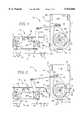
- FIG. 1is a side elevational view of a plate handling apparatus constructed in accordance with a preferred embodiment of the invention and illustrating the plate pusher of the plate feeder in its forwardmost position;
- FIG. 2is a side elevational view of the plate handling apparatus illustrating the plate pusher of the plate feeder in its rearwardmost position;
- FIG. 3is a top view of the plate handling apparatus
- FIG. 4is an end elevational view of the inlet side of the plate feeder
- FIG. 5is an end elevational view of the outlet side of the plate feeder
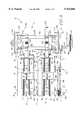
- FIG. 6is a longitudinal, vertical section view of the plate handling apparatus
- FIG. 7is a fragmented end view in partial section of the clutches and drive shaft of the plate feeder
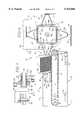
- FIG. 8is a schematic view illustrating one of the plate pushers in its rearwardmost position and depicting a pickup snout of the pickup assembly in phantom lines;
- FIG. 9is a schematic view illustrating the plate pusher in its forwardmost position while its corresponding drive chain continues to move forward;
- FIG. 10is a schematic view illustrating the plate pusher and its corresponding drive chain in their forwardmost positions.
- FIG. 11is a schematic view illustrating the plate pusher returned to its rearwardmost position.
- the plate handling apparatus 10is configured for handling at least one stack of vertically oriented plates 11 such as lead plates used in the construction of lead acid batteries and broadly includes a plate feeder assembly 12 and a pickup assembly 14.
- the plate feeder 12 and pickup assembly 14are preferably both driven by a primary drive shaft 16 (FIG. 3) which is coupled with a conventional AC motor (not shown).
- the motoris preferably coupled with a variable frequency drive or inverter so that the speed of the plate feeder 12 and pickup assembly 14 can be selectively adjusted.
- the plate feeder 12holds and sequentially feeds at least one stack of plates 11 towards the pickup assembly 14.
- the pickup assembly 14successively picks or removes the forwardmost plate from each plate stack 11 and then drops the removed plates one at a time onto a conveyor 15 (FIG. 6), which carries the plates to other processing stations.
- the plate feeder 12has an inlet side 17 and an outlet side 19.
- the plate feeder 12preferably includes a pair of side-by-side conveyor assemblies 18,20, a one-way clutch 22 and a friction clutch 24 operably coupled with the conveyor assemblies, and a crank assembly generally referred to by the numeral 26 operably coupled between the clutches 22,24 and the primary drive shaft 16 for driving the conveyor assemblies.
- the conveyor assemblies 18,20are substantially identical and each includes a pair of spaced-apart vertically extending side plates 28,30 and 32,34.
- Each of the side platesincludes a pair of horizontally-extending adjustment slots 35,37 (FIG. 1).
- Each pair of side platesis connected by a horizontally extending cross member 36,38 that is supported on a pair of horizontally extending support beams 40,42 (see FIG. 1).
- a rotatable, horizontally extending conveyor drive shaft 44extends across the inlet side 17 of the conveyor assemblies 18,20 through the side plates 28,30,32,34.
- the ends of the conveyor drive shaft 44are journaled to the outermost side plates 28,34 by bearings 46,48, and the mid-point of the drive shaft is journaled between the inside side plates 30,32 of the conveyor assemblies by bearings 50,52.
- the rightmost end of the drive shaftextends a short distance beyond the side plate 28.
- each conveyor assembly 18,20also includes a pair of rotatable idler shafts 54,56 and 58,60 at the outlet side 19 of the plate feeder.
- Each idler shaftis mounted to an elongated chain tensioning bar 62,64,66,68 that extends across substantially the entire length of its conveyor assembly 18,20.
- Each tensioning baris mounted to one corresponding side plate 28,30,32,34 by bolts extending through the adjustment slots 35,37.
- a horizontally extending support plate 70,72,74,76is mounted atop each tensioning bar.
- a pair of spaced drive sprockets 78,80 and 82,84are mounted on each section of the conveyor drive shaft 44.
- a corresponding pair of idler sprockets 85,87 and 89,91are mounted on the idler shafts 54,56 and 58,60.
- a conveyor chain 88,90,92,94is trained over each set of drive and idler sprockets.
- the undersides of the chainsrest loosely on the top surfaces of their respective support plates 70,62,74,76.
- the tension on the chainsmay be adjusted by moving the tensioning bars in the adjustment slots 35,37 of their respective side plate 28,30,32,34.
- the chainspreferably have straight side links so that they slide easily over the chain support plates.
- Each conveyor assemblyalso includes a plate pusher assembly 96,98 that supports the stack of plates 11 in an upright position on the conveyor chains 88,90,92,94.
- each pusher assembly 96,98includes a horizontally extending base plate 100,102 that rides on the conveyor chains and an upstanding pusher plate 104,106 that is hingedly connected to its base plate.
- An adjustment bracket 108,110 having an adjustment slot 109 thereinconnects the pusher plate to an upstanding support column 112,114 on the base plate. The angle of the pusher plate relative to the base plate may be adjusted by sliding the adjustment slot 109 relative to the support column to accommodate different sizes and shapes of plates.
- An elongated, upstanding plate alignment guide 116,118(FIGS. 3 and 4) is mounted to the left side plate 30,34 of each conveyor assembly 18,20 for use in aligning the plates 11 on the conveyor assembly.
- Each conveyor assemblyalso includes a pair of stops 120,122 and 124,126 (FIG. 5) each mounted to one of the side plates 28,30,32,34 at the outlet end 19 of the plate feeder. The stops serve as benchmarks to stop the forward movement of the plates 11 on the conveyor chains 88,90,92,94.
- an elongated spring steel tongue 128,130is mounted to the outlet side of each conveyor assembly 18,20.
- Each tongueextends upwardly between its idler sprockets 85,87,89,91 and terminates between its benchmark stops 120,122,124,126.
- the tonguesurge the stacks of plates 11 slightly rearward to prevent the pickup assembly 14 from striking the forwardmost plates in the stacks during plate pickup.
- the one-way clutch 22 and friction clutch 24are mounted to the end of the conveyor drive shaft 44 that extends beyond the side plate 28.
- the clutchesare secured on the drive shaft by a removable collar 132.
- the one-way clutch 22includes a downwardly extending clutch arm 134, and the friction clutch 24 includes an upstanding clutch arm 136.
- crank assembly 26is operably coupled between the clutches 22,24 and the primary drive shaft 16 for reciprocating the conveyor drive shaft 44 during rotation of the primary drive shaft.
- the crank assemblyincludes a crank 138 rotatably coupled with the primary drive shaft, a ratio bar 140, and a plurality of tie rods 142,144,146 interconnecting the crank, ratio bar, and clutches.
- the ratio bar 140is an elongated, generally vertically extending, flat bar that is pivotally mounted to the side plate 28 of the conveyor assembly 18 by a pivot bearing 148.
- the pivot bearingis supported on a mounting bracket 150 attached to the side plate 28.
- the upper end of the ratio baris connected with the crank 138 by the tie rod 142.
- the tie rod 142reciprocates the ratio bar about its pivot axis 148 as the crank is rotated by the primary drive shaft 16.
- the lower end of the ratio bar 140is operably coupled with the arm 134 of the one-way clutch 22 by the tie rod 144.
- the section of the ratio bar above its pivot axis 148is operably coupled with the arm 136 of the friction clutch 24 by the tie rod 146.
- the one-way clutch tie rod 144is mounted further from the pivot axis 148 of the ratio bar than is the one-way clutch tie rod 144.
- the one-way clutch tie rod 144 and friction clutch tie rod 146are equidistant from the axis of the conveyor drive shaft 44. The importance of this mounting arrangement is discussed below.
- the pickup assembly 14which is best illustrated in FIGS. 3 and 6, includes a rotatable vacuum head 154 mounted on a vacuum head drive shaft 156.
- the vacuum headis connected to a vacuum chamber 155 which is coupled with a suitable source of vacuum by a vacuum supply port 157.
- the vacuum head drive shaft 156is journaled between a pair of spaced apart, vertically extending support plates 158,160 that depend from a pair of horizontally-extending support beams 162,164 (see FIG. 1).
- One end of the vacuum head drive shaftis attached to a drive sprocket 166 that is coupled with the primary drive shaft 16 by a drive chain 168.
- Each support plate 158,160includes vertically-extending front 170,172 and rear 174,176 walls and an arcuate lower wall 178,180 (FIGS. 1,6). As illustrated in FIGS. 1 and 2, the support plate 158 includes a horizontally extending, arcuate adjustment slot 182 positioned along the periphery of its arcuate lower wall 178. Similarly, as illustrated in FIG. 6, the support plate 160 includes an arcuate, upwardly extending adjustment slot 184 positioned along the periphery of the intersection of its front wall 172 and its arcuate lower wall 180. The purpose of the adjustment slots is discussed below.
- the vacuum head 154is preferably square in cross-section and includes four side plates 186 (FIG. 6). Each side plate has a pair of longitudinally spaced vacuum slots or openings 194 therein (only one vacuum slot being shown for each side plate). The purpose of the vacuum slots is discussed below.
- the pick up assembly 14also includes at least two outwardly extending pickup snouts 202 mounted to one of the vacuum head side plates 186.
- the two pickup snoutsare longitudinally spaced on the side plate so that each one rotates between the conveyor chains 88,90,92,94 of one of the conveyor assemblies 18,20.
- the pickup assemblyincludes a set of four pickup snouts spaced equally along the periphery of the vacuum head for each conveyor assembly.
- the pickup snoutsare each generally hollow and trapezoidal in cross section. As best illustrated in FIG. 3, the outwardly extending end of each snout has a plurality of air holes 206 therein.
- the base of each snouthas a vacuum slot 208 therein that is in alignment with one of the vacuum slots 194 of its respective side plate 186.
- the pickup assembly 14also includes valve structure interposed between each pickup snout 202 and its respective vacuum head side plate 186 for controlling the introduction of vacuum pressure to the pickup snout.
- the preferred valve structureincludes a plurality of elongated, flat valve plates 210 (FIG. 3) that are each slidably mounted between one vacuum head side plate 186 and its associated snout 202 by a plurality of clips 212. As depicted on the upper three snouts of FIG. 6, each valve plate includes a pair (only one being shown) of longitudinally spaced vacuum slots 214 therein.
- Each valve plate 210is shiftable between an open position wherein it is shifted toward the primary drive shaft 16 and a closed position wherein it is shifted away from the primary drive shaft.
- its vacuum slots 214are in substantial alignment with their corresponding side plate vacuum slots 194 and snout vacuum slots 208 as depicted by the upper three snouts of FIG. 6.
- the vacuum pressureis transferred to the snouts 202 through the vacuum slots 194,208,214 and to the air holes 206 in the ends of the snouts 202. This enables each snout 202 to pick up and hold a plate as described below.
- the valve plates 210are shifted between their opened and closed positions during rotation of the vacuum head 154 by camming action.
- the pick-up assembly 14includes a first, ramp-shaped cam 216 mounted in the adjustment slot 182 on the support plate 158, and a second ramp-shaped cam 218 mounted in the adjustment slot 184 on the support plate 160.
- the camscan be positioned anywhere along the length of their respective adjustment slots.
- a pair of corresponding cam follower rollers 220,222are mounted to the ends of each slidable valve plate 210.
- the rollersare strategically positioned so that they each contact one of the cams 216,218 during rotation of the vacuum head for shifting their corresponding valve plates 210 between their open and closed positions.
- the camshifts the roller and its corresponding valve plate 210 toward the primary drive shaft 16 as viewed from FIG. 3. This aligns the vacuum slots 194,208,214 and therefore transfers vacuum pressure from the vacuum head to the corresponding snouts 202.
- the camshifts the roller and its corresponding valve plate 210 away from the primary drive shaft 16 as viewed from FIG. 3. This shifts the vacuum slots 214 out of alignment with the vacuum slots 194,208 and therefore disconnects the vacuum pressure from the snouts.
- An operatorbegins a plate handling operation by first turning the drive motor on and adjusting the speed of the motor with the variable frequency drive.
- the motorrotates the primary drive shaft 16, which in turn rotates the vacuum head 154 and reciprocates the ratio bar 140 of the crank assembly 26.
- the operatorplaces a stack of plates 11 and a pusher assembly 96,98 on one or both of the conveyor assemblies 18,20.
- the speed of the primary drive shaftcan be varied and additional plates can be added to the stack 11 at any time during operation of the apparatus.
- the primary drive shaft 16 and crank 138reciprocate the ratio bar 140 about its pivot axis.
- the ratio barin turn alternately rotates the clutches 22,24 clockwise and then counterclockwise as viewed from FIGS. 1 and 2 for rotating the conveyor drive shaft 44.
- the conveyor drive shaft 44in turn moves the conveyor chains 88,90,92,94 and pusher assemblies 96,98 toward or away from the pick-up snouts 202.
- the top of the ratio bar 140when the top of the ratio bar 140 is shifted rightward as illustrated in FIG. 1, it rotates the clutch arms 134,136 and their associated clutches 22,24 in a clockwise direction.
- the clutchesin turn rotate the conveyor drive shaft 44 in a clockwise direction and move the conveyor chains 88,90,92,94 and the corresponding pusher assemblies 96,98 forward a first distance toward the pick-up assembly.
- the one-way clutch tie rod 144is spaced further from the ratio bar pivot axis 148 than is the friction clutch tie rod 146, the one way clutch 22 and drive shaft 44 rotate clockwise slightly faster than the friction clutch 24. This causes the friction clutch to slip slightly on the conveyor drive shaft 44.
- the friction clutch 24rotates in a counterclockwise direction.
- the friction clutchwhich does not slip during counterclockwise rotation, in turn rotates the conveyor drive shaft 44 in a counterclockwise direction to move the conveyor chains 88,90,92,94 and pusher assemblies 96,98 rearward a second distance away from the pick-up assembly 14.
- the ratio barmoves the one-way clutch mounting arm 134 counterclockwise, the one-way clutch 22 freely rotates on the conveyor drive shaft.
- the friction clutch 24rotates the conveyor drive shaft 44 counterclockwise a distance which is less than the clockwise travel of the conveyor drive shaft. This causes the pusher assemblies 96,98 to be moved forward toward the pick-up assembly 14 a greater distance than they are moved away from the pickup assembly. The importance of this travel differential is discussed below.
- the distance differentialcan be conveniently adjusted by repositioning either the friction clutch tie rod 146 or the one-way clutch tie rod 144 relative to the pivot axis 148 of the ratio bar.
- the primary drive shaft 16While the feeder assembly 12 shifts the stack of plates 11 toward and away from the pick-up assembly 14, the primary drive shaft 16 also rotates the vacuum head 154 and its associated snouts 202 between the conveyor chains.
- the snoutsare valved as described above so that they are connected to the vacuum pressure as they rotate in front of the plates 11 and then disconnected from the vacuum pressure as they pass over the conveyor assembly 15. This permits each snout to remove the forwardmost plate from its associated stack as it passes thereby, hold the removed plate as the vacuum head continues to rotate, and then release the plate over the conveyor 15.
- the operation of the plate feeder 12 and pickup head 14are sequenced so that the conveyor chains 88,90,92,94 and their associated pusher assemblies 96,98 are in their rearward most positions as the snouts 202 rotate in front of the stacks of plates 11. This permits a snout to remove the forwardmost plate from its corresponding stack and to continue to rotate by the stack without striking the tail end of the removed plate against the remaining plates in the stack. After the snouts 202 have passed by the stacks, the pusher assemblies 96,98 are then shifted to their forwardmost positions and then back to their rearwardmost positions before the next snouts arrive to remove the next forwardmost plates from the stacks.
- the pusher assembliesare moved forward toward the pick-up assembly a greater distance than they are moved away from the pickup assembly. This accounts for the thickness of the removed plates so that the stacks are always positioned a predetermined distance from the pickup head regardless of how many plates have been removed.
- FIGS. 8-11illustrate the operation of one conveyor assembly 18.
- the axis lines extending through the conveyor drive shaft 44 in these figuresrepresent the axes of the clutch arms 134,136.
- the top axis line 224represents the axis for the friction clutch, and the bottom axis line 226 represents the axis for the one-way clutch.
- the solid axis linesrepresent the actual position of the clutches for that particular figure, whereas the dashed lines represent the reference starting point for the clutches.
- the reference line 228 extending through the conveyor chain 88 near the idler sprocket 85indicates the position of the chain in each of the figures.
- the clutchesare both shifted counterclockwise so that the pusher assembly 96 is moved away from the pick-up assembly 14.
- the snouts 202 on the vacuum head 154rotate in front of the stack 11 and remove the forwardmost plate from the stack.
- the friction clutch arm 136 and the one-way clutch arm 134are rotated counterclockwise to their starting positions so that the pusher assembly 96 is once again moved away from the pickup assembly 14.
- another snout 202is rotated in front of the stack 11 to remove the new forwardmost plate from the stack.
- the pusher assembly 96is slightly closer to the pickup assembly than it was in FIG. 8 because the ratio bar 140 and clutches 22,24 moved the pusher assembly forward a greater distance than rearward. This distance differential accounts for the thickness of the removed plate.
- the plate handling apparatus 10 of the present inventionis preferably configured for handling stacks of vertically oriented lead plates 11 used in the construction of lead acid batteries, it may be used equally well with other types of generally flat plates.
- the preferred plate feeder 12includes a pair of side-by-side conveyor assemblies 18,20, and the preferred vacuum head 154 includes snouts 202 for simultaneously removing plates from the two conveyor assemblies, the plate feeder and vacuum head may be equipped with any number of conveyor assemblies and pick-up snouts.
Landscapes
- Engineering & Computer Science (AREA)
- Mechanical Engineering (AREA)
- Sheets, Magazines, And Separation Thereof (AREA)
- Vending Machines For Individual Products (AREA)
- Formation And Processing Of Food Products (AREA)
- Preliminary Treatment Of Fibers (AREA)
- Macromolecular Compounds Obtained By Forming Nitrogen-Containing Linkages In General (AREA)
Abstract
Description
Claims (24)
Priority Applications (6)
| Application Number | Priority Date | Filing Date | Title |
|---|---|---|---|
| US08/812,372US5934866A (en) | 1997-01-30 | 1997-03-05 | Plate feeder apparatus |
| PCT/US1998/004220WO1998039240A1 (en) | 1997-03-05 | 1998-03-05 | Plate feeder apparatus |
| AU66836/98AAU6683698A (en) | 1997-03-05 | 1998-03-05 | Plate feeder apparatus |
| DE69824022TDE69824022D1 (en) | 1997-03-05 | 1998-03-05 | PANEL feeder |
| EP98908923AEP1015365B1 (en) | 1997-03-05 | 1998-03-05 | Plate feeder apparatus |
| AT98908923TATE267132T1 (en) | 1997-03-05 | 1998-03-05 | PLATE FEEDER |
Applications Claiming Priority (2)
| Application Number | Priority Date | Filing Date | Title |
|---|---|---|---|
| US3631197P | 1997-01-30 | 1997-01-30 | |
| US08/812,372US5934866A (en) | 1997-01-30 | 1997-03-05 | Plate feeder apparatus |
Publications (1)
| Publication Number | Publication Date |
|---|---|
| US5934866Atrue US5934866A (en) | 1999-08-10 |
Family
ID=25209373
Family Applications (1)
| Application Number | Title | Priority Date | Filing Date |
|---|---|---|---|
| US08/812,372Expired - LifetimeUS5934866A (en) | 1997-01-30 | 1997-03-05 | Plate feeder apparatus |
Country Status (6)
| Country | Link |
|---|---|
| US (1) | US5934866A (en) |
| EP (1) | EP1015365B1 (en) |
| AT (1) | ATE267132T1 (en) |
| AU (1) | AU6683698A (en) |
| DE (1) | DE69824022D1 (en) |
| WO (1) | WO1998039240A1 (en) |
Cited By (36)
| Publication number | Priority date | Publication date | Assignee | Title |
|---|---|---|---|---|
| US6152283A (en)* | 1997-07-02 | 2000-11-28 | Fuji Machine Mfg. Co., Ltd. | Circuit-component supplying method and circuit-component feeder |
| US20040193554A1 (en)* | 2003-03-28 | 2004-09-30 | Hillerich Thomas A. | Automated induction systems and methods for mail and/or other objects |
| US20040245714A1 (en)* | 2003-05-13 | 2004-12-09 | Ryan Patrick J. | Enhanced object-feeder pre-processing system |
| US20050077217A1 (en)* | 2003-03-28 | 2005-04-14 | Hillerich Thomas A. | Carrier for mail and/or the like thin objects |
| US20050282692A1 (en)* | 2004-06-17 | 2005-12-22 | Galen Redden | Removable flexible roller |
| US20060000752A1 (en)* | 2003-03-28 | 2006-01-05 | Northrop Grumman Corporation | Stack correction system and method |
| EP1637237A2 (en) | 1997-09-30 | 2006-03-22 | Daramic, Inc. | Battery plate feeding and handling apparatus |
| US20060087068A1 (en)* | 2004-09-24 | 2006-04-27 | Northrop Grumman Corporation | Anti-toppling device for mail and/or the like |
| US20060099065A1 (en)* | 2004-08-27 | 2006-05-11 | Northrop Grumman Corporation | Preparation operator flex-station for carrier preparation |
| US7226271B1 (en) | 2004-05-24 | 2007-06-05 | Honda Motor Co., Ltd. | Apparatus and method for feeding plates |
| US20070138743A1 (en)* | 2005-12-19 | 2007-06-21 | Bally Gaming Inc. | Card shoe with force resist mechanism |
| US20070216092A1 (en)* | 2006-03-15 | 2007-09-20 | Bally Gaming, Inc. | Card shoe for holding playing cards |
| US20070287535A1 (en)* | 2006-05-23 | 2007-12-13 | Bally Gaming, Inc. | Systems, methods and articles to facilitate playing card games with selectable odds |
| US20080184856A1 (en)* | 2005-06-28 | 2008-08-07 | Mitek Holdings, Inc. | Automated System For Precision Cutting Crooked Lumber |
| WO2009045806A1 (en)* | 2007-10-04 | 2009-04-09 | Solbern Llc | Tortilla destacking device |
| US7766171B2 (en) | 2008-02-28 | 2010-08-03 | Northrop Grumman Systems Corporation | Rigid storage tray for flat and letter mail |
| US20100264575A1 (en)* | 2009-04-20 | 2010-10-21 | Bowe Bell + Howell Company | Booklet feeder systems and methods |
| US8038153B2 (en) | 2006-05-23 | 2011-10-18 | Bally Gaming, Inc. | Systems, methods and articles to facilitate playing card games |
| US8052519B2 (en) | 2006-06-08 | 2011-11-08 | Bally Gaming, Inc. | Systems, methods and articles to facilitate lockout of selectable odds/advantage in playing card games |
| US8074987B2 (en) | 2005-02-10 | 2011-12-13 | Bally Gaming, Inc. | Systems and methods for processing playing cards collected from a gaming table |
| US20120076632A1 (en)* | 2006-03-10 | 2012-03-29 | Tbs Engineering Limited | Apparatus for Placing Battery Plates |
| US8342533B2 (en) | 2005-09-12 | 2013-01-01 | Bally Gaming, Inc. | Systems, methods and articles to facilitate playing card games with multi-compartment playing card receivers |
| US8342932B2 (en) | 2005-09-12 | 2013-01-01 | Bally Gaming, Inc. | Systems, methods and articles to facilitate playing card games with intermediary playing card receiver |
| US8550464B2 (en) | 2005-09-12 | 2013-10-08 | Bally Gaming, Inc. | Systems, methods and articles to facilitate playing card games with selectable odds |
| US20140271087A1 (en)* | 2013-03-12 | 2014-09-18 | United States Postal Service | System and method of automatic feeder stack management |
| US8998692B2 (en) | 2006-06-21 | 2015-04-07 | Bally Gaming, Inc. | Systems, methods and articles to facilitate delivery of sets or packets of playing cards |
| US9101820B2 (en) | 2006-11-09 | 2015-08-11 | Bally Gaming, Inc. | System, method and apparatus to produce decks for and operate games played with playing cards |
| US9339723B2 (en) | 2007-06-06 | 2016-05-17 | Bally Gaming, Inc. | Casino card handling system with game play feed to mobile device |
| US9346580B2 (en) | 2011-02-22 | 2016-05-24 | Graphic Packaging International, Inc. | Carton decasing system |
| US9346224B2 (en)* | 2010-12-16 | 2016-05-24 | Novartis Ag | Method and apparatus for transferring objects between two consecutive processing stations being operated with different cycle speeds |
| US9573774B2 (en) | 2012-09-10 | 2017-02-21 | Rosendahl Nextrom Gmbh | Device for handling plate-shaped objects |
| US9751704B2 (en) | 2013-03-12 | 2017-09-05 | United States Postal Service | Article feeder with a retractable product guide |
| US9834395B2 (en) | 2013-03-13 | 2017-12-05 | United States Postal Service | Anti-rotation device and method of use |
| US9856047B2 (en)* | 2011-02-22 | 2018-01-02 | Graphic Packaging International, Inc. | Carton decasing system |
| US9943883B2 (en) | 2013-03-12 | 2018-04-17 | United States Postal Service | System and method of unloading a container of items |
| US10287107B2 (en) | 2013-03-14 | 2019-05-14 | United States Postal Service | System and method of article feeder operation |
Families Citing this family (3)
| Publication number | Priority date | Publication date | Assignee | Title |
|---|---|---|---|---|
| WO2007136242A1 (en)* | 2006-05-23 | 2007-11-29 | Buhrs-Zaandam B.V. | Method and device for unstacking a stack of flexible sheets |
| CN110085783B (en)* | 2019-04-17 | 2021-09-17 | 安徽中能电源有限公司 | Cooling and carrying system for acid-adding of storage battery |
| CN114013963A (en)* | 2021-12-07 | 2022-02-08 | 安徽普瑞普勒传热技术有限公司 | Plate transferring system and method for plate heat exchanger |
Citations (21)
| Publication number | Priority date | Publication date | Assignee | Title |
|---|---|---|---|---|
| US3240488A (en)* | 1963-07-15 | 1966-03-15 | Pitney Bowes Inc | Document handling apparatus having a vacuum controlled pack advancer |
| BE676137A (en)* | 1965-02-05 | 1966-06-16 | ||
| US3718217A (en)* | 1969-08-22 | 1973-02-27 | A Stobb | Apparatus for feeding signatures |
| US4407063A (en)* | 1981-04-03 | 1983-10-04 | Johnson Peter E | Method and apparatus for fabricating battery plate envelopes |
| US4462745A (en)* | 1982-03-18 | 1984-07-31 | Johnson Peter E | Plate feed apparatus |
| US4710089A (en)* | 1986-05-29 | 1987-12-01 | Velten & Pulver, Inc. | Article unstacking system |
| JPS638162A (en)* | 1986-06-24 | 1988-01-13 | Omron Tateisi Electronics Co | Paper sheet stacker |
| WO1988001598A1 (en)* | 1986-09-05 | 1988-03-10 | Data Card Corporation | Input hopper apparatus and method |
| GB2198711A (en)* | 1986-12-19 | 1988-06-22 | Shibuya Kogyo Co Ltd | Carton delivery apparatus |
| US4757985A (en)* | 1986-07-09 | 1988-07-19 | Compagnie General D'automatisme Cga-Hbs | Device for unstacking flat objects |
| US4758126A (en)* | 1987-02-19 | 1988-07-19 | Johnson Peter E | Plate feed apparatus |
| US4822234A (en)* | 1987-11-16 | 1989-04-18 | Tekmax Inc. | Plate feed apparatus |
| US4824308A (en)* | 1986-07-29 | 1989-04-25 | Omera Spa | Separating and lifting device for stacked-up flat elements |
| US4824307A (en)* | 1988-02-11 | 1989-04-25 | Tekmax Inc. | Apparatus for vertically stacking battery plates |
| US4867432A (en)* | 1984-05-08 | 1989-09-19 | Gte Directories Press, Inc. | Signature handling apparatus and method |
| US5104111A (en)* | 1989-02-17 | 1992-04-14 | Minolta Camera Kabushiki Kaisha | Sheet feed arrangement |
| US5131899A (en)* | 1988-04-27 | 1992-07-21 | Tokyo Automatic Machinery Works, Ltd. | Magazine and method of feeding articles |
| US5215428A (en)* | 1989-12-22 | 1993-06-01 | Civiemmes S.R.L. | Apparatus for the vertical, automatic stacking of sheets |
| US5289666A (en)* | 1986-03-20 | 1994-03-01 | T. W. Hamilton Design Ltd. | Apparatus for applying label tags |
| US5379992A (en)* | 1992-08-10 | 1995-01-10 | Finmeccanica S.P.A. | Mail sorting device |
| US5511936A (en)* | 1993-04-07 | 1996-04-30 | Licentia Patent-Verwaltungs-Gmbh | Separation method and device |
Family Cites Families (1)
| Publication number | Priority date | Publication date | Assignee | Title |
|---|---|---|---|---|
| DE3606178C1 (en)* | 1986-02-26 | 1987-07-16 | Lazar Peter | Process for separating sheets and sheet separator for carrying out this process |
- 1997
- 1997-03-05USUS08/812,372patent/US5934866A/ennot_activeExpired - Lifetime
- 1998
- 1998-03-05DEDE69824022Tpatent/DE69824022D1/ennot_activeExpired - Lifetime
- 1998-03-05AUAU66836/98Apatent/AU6683698A/ennot_activeAbandoned
- 1998-03-05EPEP98908923Apatent/EP1015365B1/ennot_activeExpired - Lifetime
- 1998-03-05WOPCT/US1998/004220patent/WO1998039240A1/enactiveIP Right Grant
- 1998-03-05ATAT98908923Tpatent/ATE267132T1/ennot_activeIP Right Cessation
Patent Citations (21)
| Publication number | Priority date | Publication date | Assignee | Title |
|---|---|---|---|---|
| US3240488A (en)* | 1963-07-15 | 1966-03-15 | Pitney Bowes Inc | Document handling apparatus having a vacuum controlled pack advancer |
| BE676137A (en)* | 1965-02-05 | 1966-06-16 | ||
| US3718217A (en)* | 1969-08-22 | 1973-02-27 | A Stobb | Apparatus for feeding signatures |
| US4407063A (en)* | 1981-04-03 | 1983-10-04 | Johnson Peter E | Method and apparatus for fabricating battery plate envelopes |
| US4462745A (en)* | 1982-03-18 | 1984-07-31 | Johnson Peter E | Plate feed apparatus |
| US4867432A (en)* | 1984-05-08 | 1989-09-19 | Gte Directories Press, Inc. | Signature handling apparatus and method |
| US5289666A (en)* | 1986-03-20 | 1994-03-01 | T. W. Hamilton Design Ltd. | Apparatus for applying label tags |
| US4710089A (en)* | 1986-05-29 | 1987-12-01 | Velten & Pulver, Inc. | Article unstacking system |
| JPS638162A (en)* | 1986-06-24 | 1988-01-13 | Omron Tateisi Electronics Co | Paper sheet stacker |
| US4757985A (en)* | 1986-07-09 | 1988-07-19 | Compagnie General D'automatisme Cga-Hbs | Device for unstacking flat objects |
| US4824308A (en)* | 1986-07-29 | 1989-04-25 | Omera Spa | Separating and lifting device for stacked-up flat elements |
| WO1988001598A1 (en)* | 1986-09-05 | 1988-03-10 | Data Card Corporation | Input hopper apparatus and method |
| GB2198711A (en)* | 1986-12-19 | 1988-06-22 | Shibuya Kogyo Co Ltd | Carton delivery apparatus |
| US4758126A (en)* | 1987-02-19 | 1988-07-19 | Johnson Peter E | Plate feed apparatus |
| US4822234A (en)* | 1987-11-16 | 1989-04-18 | Tekmax Inc. | Plate feed apparatus |
| US4824307A (en)* | 1988-02-11 | 1989-04-25 | Tekmax Inc. | Apparatus for vertically stacking battery plates |
| US5131899A (en)* | 1988-04-27 | 1992-07-21 | Tokyo Automatic Machinery Works, Ltd. | Magazine and method of feeding articles |
| US5104111A (en)* | 1989-02-17 | 1992-04-14 | Minolta Camera Kabushiki Kaisha | Sheet feed arrangement |
| US5215428A (en)* | 1989-12-22 | 1993-06-01 | Civiemmes S.R.L. | Apparatus for the vertical, automatic stacking of sheets |
| US5379992A (en)* | 1992-08-10 | 1995-01-10 | Finmeccanica S.P.A. | Mail sorting device |
| US5511936A (en)* | 1993-04-07 | 1996-04-30 | Licentia Patent-Verwaltungs-Gmbh | Separation method and device |
Cited By (54)
| Publication number | Priority date | Publication date | Assignee | Title |
|---|---|---|---|---|
| US6152283A (en)* | 1997-07-02 | 2000-11-28 | Fuji Machine Mfg. Co., Ltd. | Circuit-component supplying method and circuit-component feeder |
| EP1637237A2 (en) | 1997-09-30 | 2006-03-22 | Daramic, Inc. | Battery plate feeding and handling apparatus |
| US7195236B2 (en) | 2003-03-28 | 2007-03-27 | Northrop Grumman Corporation | Automated induction systems and methods for mail and/or other objects |
| US20040193554A1 (en)* | 2003-03-28 | 2004-09-30 | Hillerich Thomas A. | Automated induction systems and methods for mail and/or other objects |
| US20050077217A1 (en)* | 2003-03-28 | 2005-04-14 | Hillerich Thomas A. | Carrier for mail and/or the like thin objects |
| US20060000752A1 (en)* | 2003-03-28 | 2006-01-05 | Northrop Grumman Corporation | Stack correction system and method |
| US20040245714A1 (en)* | 2003-05-13 | 2004-12-09 | Ryan Patrick J. | Enhanced object-feeder pre-processing system |
| US7226271B1 (en) | 2004-05-24 | 2007-06-05 | Honda Motor Co., Ltd. | Apparatus and method for feeding plates |
| US20050282692A1 (en)* | 2004-06-17 | 2005-12-22 | Galen Redden | Removable flexible roller |
| US20060099065A1 (en)* | 2004-08-27 | 2006-05-11 | Northrop Grumman Corporation | Preparation operator flex-station for carrier preparation |
| US20060087068A1 (en)* | 2004-09-24 | 2006-04-27 | Northrop Grumman Corporation | Anti-toppling device for mail and/or the like |
| US7467792B2 (en) | 2004-09-24 | 2008-12-23 | Northrop Grumman Corporation | Anti-toppling device for mail with retractable protrusion |
| US8074987B2 (en) | 2005-02-10 | 2011-12-13 | Bally Gaming, Inc. | Systems and methods for processing playing cards collected from a gaming table |
| US7870879B2 (en) | 2005-06-28 | 2011-01-18 | Mitek Holdings, Inc. | Automated system for precision cutting crooked lumber |
| US20080184856A1 (en)* | 2005-06-28 | 2008-08-07 | Mitek Holdings, Inc. | Automated System For Precision Cutting Crooked Lumber |
| US8550464B2 (en) | 2005-09-12 | 2013-10-08 | Bally Gaming, Inc. | Systems, methods and articles to facilitate playing card games with selectable odds |
| US8342932B2 (en) | 2005-09-12 | 2013-01-01 | Bally Gaming, Inc. | Systems, methods and articles to facilitate playing card games with intermediary playing card receiver |
| US8342533B2 (en) | 2005-09-12 | 2013-01-01 | Bally Gaming, Inc. | Systems, methods and articles to facilitate playing card games with multi-compartment playing card receivers |
| US20070138743A1 (en)* | 2005-12-19 | 2007-06-21 | Bally Gaming Inc. | Card shoe with force resist mechanism |
| US20120076632A1 (en)* | 2006-03-10 | 2012-03-29 | Tbs Engineering Limited | Apparatus for Placing Battery Plates |
| US20070216092A1 (en)* | 2006-03-15 | 2007-09-20 | Bally Gaming, Inc. | Card shoe for holding playing cards |
| US20070287535A1 (en)* | 2006-05-23 | 2007-12-13 | Bally Gaming, Inc. | Systems, methods and articles to facilitate playing card games with selectable odds |
| US8038153B2 (en) | 2006-05-23 | 2011-10-18 | Bally Gaming, Inc. | Systems, methods and articles to facilitate playing card games |
| US8100753B2 (en) | 2006-05-23 | 2012-01-24 | Bally Gaming, Inc. | Systems, methods and articles to facilitate playing card games with selectable odds |
| US8052519B2 (en) | 2006-06-08 | 2011-11-08 | Bally Gaming, Inc. | Systems, methods and articles to facilitate lockout of selectable odds/advantage in playing card games |
| US8998692B2 (en) | 2006-06-21 | 2015-04-07 | Bally Gaming, Inc. | Systems, methods and articles to facilitate delivery of sets or packets of playing cards |
| US9101820B2 (en) | 2006-11-09 | 2015-08-11 | Bally Gaming, Inc. | System, method and apparatus to produce decks for and operate games played with playing cards |
| US10008076B2 (en) | 2007-06-06 | 2018-06-26 | Bally Gaming, Inc. | Casino card handling system with game play feed |
| US10504337B2 (en) | 2007-06-06 | 2019-12-10 | Bally Gaming, Inc. | Casino card handling system with game play feed |
| US9339723B2 (en) | 2007-06-06 | 2016-05-17 | Bally Gaming, Inc. | Casino card handling system with game play feed to mobile device |
| US9659461B2 (en) | 2007-06-06 | 2017-05-23 | Bally Gaming, Inc. | Casino card handling system with game play feed to mobile device |
| WO2009045806A1 (en)* | 2007-10-04 | 2009-04-09 | Solbern Llc | Tortilla destacking device |
| US20090092475A1 (en)* | 2007-10-04 | 2009-04-09 | Foulon Jr Gilbert M | Tortilla destacking device |
| US7736121B2 (en) | 2007-10-04 | 2010-06-15 | Solbern Llc | Tortilla destacking device |
| US7766171B2 (en) | 2008-02-28 | 2010-08-03 | Northrop Grumman Systems Corporation | Rigid storage tray for flat and letter mail |
| US20100264575A1 (en)* | 2009-04-20 | 2010-10-21 | Bowe Bell + Howell Company | Booklet feeder systems and methods |
| US9346224B2 (en)* | 2010-12-16 | 2016-05-24 | Novartis Ag | Method and apparatus for transferring objects between two consecutive processing stations being operated with different cycle speeds |
| US9856047B2 (en)* | 2011-02-22 | 2018-01-02 | Graphic Packaging International, Inc. | Carton decasing system |
| US9346580B2 (en) | 2011-02-22 | 2016-05-24 | Graphic Packaging International, Inc. | Carton decasing system |
| US9573774B2 (en) | 2012-09-10 | 2017-02-21 | Rosendahl Nextrom Gmbh | Device for handling plate-shaped objects |
| US10737298B2 (en) | 2013-03-12 | 2020-08-11 | United States Postal Service | System and method of unloading a container of items |
| US9751704B2 (en) | 2013-03-12 | 2017-09-05 | United States Postal Service | Article feeder with a retractable product guide |
| US9943883B2 (en) | 2013-03-12 | 2018-04-17 | United States Postal Service | System and method of unloading a container of items |
| US9340377B2 (en)* | 2013-03-12 | 2016-05-17 | United States Postal Service | System and method of automatic feeder stack management |
| US10131513B2 (en) | 2013-03-12 | 2018-11-20 | United States Postal Service | System and method of automatic feeder stack management |
| US20140271087A1 (en)* | 2013-03-12 | 2014-09-18 | United States Postal Service | System and method of automatic feeder stack management |
| US10723577B2 (en) | 2013-03-12 | 2020-07-28 | United States Postal Service | System and method of automatic feeder stack management |
| US10894679B2 (en) | 2013-03-13 | 2021-01-19 | United States Postal Service | Anti-rotation device and method of use |
| US10421630B2 (en) | 2013-03-13 | 2019-09-24 | United States Postal Service | Biased anti-rotation device and method of use |
| US9834395B2 (en) | 2013-03-13 | 2017-12-05 | United States Postal Service | Anti-rotation device and method of use |
| US10745224B2 (en) | 2013-03-14 | 2020-08-18 | United States Postal Service | System and method of article feeder operation |
| US10815083B2 (en) | 2013-03-14 | 2020-10-27 | United States Postal Service | System and method of article feeder operation |
| US10287107B2 (en) | 2013-03-14 | 2019-05-14 | United States Postal Service | System and method of article feeder operation |
| US11319174B2 (en) | 2013-03-14 | 2022-05-03 | United States Postal Service | System and method of article feeder operation |
Also Published As
| Publication number | Publication date |
|---|---|
| EP1015365A1 (en) | 2000-07-05 |
| DE69824022D1 (en) | 2004-06-24 |
| WO1998039240A1 (en) | 1998-09-11 |
| EP1015365A4 (en) | 2002-09-04 |
| ATE267132T1 (en) | 2004-06-15 |
| EP1015365B1 (en) | 2004-05-19 |
| AU6683698A (en) | 1998-09-22 |
Similar Documents
| Publication | Publication Date | Title |
|---|---|---|
| US5934866A (en) | Plate feeder apparatus | |
| US6095316A (en) | Battery plate feeding and handling apparatus | |
| US4618054A (en) | Equipment for feeding packaging blanks to a packaging machine | |
| US6550608B1 (en) | Carton feeding system for packaging machine | |
| US4249847A (en) | Apparatus for transporting boards | |
| US4373710A (en) | Apparatus for inserting supplementary material into newspaper jackets | |
| CN111745447B (en) | A feeding device for pipe cutting | |
| US4678074A (en) | Apparatus for separating objects (packages) from a continuous row of objects | |
| EP1637237B1 (en) | Battery plate feeding and handling apparatus | |
| US6024533A (en) | Battery plate feeding and handling apparatus | |
| US20010010282A1 (en) | Turning device for graphic publishing products in a conveyor line and/or packaging machine | |
| JP4716440B2 (en) | Product processing system for rolling mill | |
| JP5255413B2 (en) | Alignment feeder | |
| US6655902B2 (en) | Apparatus for stacking elongated members | |
| US1236181A (en) | Signature-gatherer. | |
| JPH05155435A (en) | Device to carry sheet paper accumulated body | |
| JPH09278165A (en) | Lining-up device | |
| AU4887899A (en) | Method to produce printed articles by inserting at least one part-product into a main product and device to carry out the method | |
| US2723602A (en) | Automatic partition strip feeding mechanism | |
| US4592709A (en) | Apparatus for insertion sticks into freezing pockets | |
| CN222626841U (en) | Hinge threading device | |
| SU1321504A1 (en) | Arrangement for feeding material into working zone of press and removing pressed articles therefrom | |
| US3217766A (en) | Handling and transfer mechanism for small elongate articles | |
| EP1247770B1 (en) | Apparatus for transferring fruit products from one conveyor to another conveyor arranged at right angles to the first one | |
| CN118321889A (en) | Hinge shaft penetrating device |
Legal Events
| Date | Code | Title | Description |
|---|---|---|---|
| AS | Assignment | Owner name:GELCO INTERNATIONAL L.L.C., KANSAS Free format text:ASSIGNMENT OF ASSIGNORS INTEREST;ASSIGNOR:REDDEN, GALEN H.;REEL/FRAME:008713/0349 Effective date:19970825 | |
| STCF | Information on status: patent grant | Free format text:PATENTED CASE | |
| AS | Assignment | Owner name:DARAMIC, INC., MASSACHUSETTS Free format text:ASSIGNMENT OF ASSIGNORS INTEREST;ASSIGNOR:GELCO INTERNATIONAL LLC;REEL/FRAME:011474/0539 Effective date:20001220 | |
| FEPP | Fee payment procedure | Free format text:PAT HOLDER NO LONGER CLAIMS SMALL ENTITY STATUS, ENTITY STATUS SET TO UNDISCOUNTED (ORIGINAL EVENT CODE: STOL); ENTITY STATUS OF PATENT OWNER: LARGE ENTITY | |
| REFU | Refund | Free format text:REFUND - SURCHARGE, PETITION TO ACCEPT PYMT AFTER EXP, UNINTENTIONAL (ORIGINAL EVENT CODE: R2551); ENTITY STATUS OF PATENT OWNER: LARGE ENTITY | |
| FPAY | Fee payment | Year of fee payment:4 | |
| AS | Assignment | Owner name:DARAMIC, LLC, SOUTH CAROLINA Free format text:CHANGE OF NAME;ASSIGNOR:DARAMIC, INC.;REEL/FRAME:014822/0729 Effective date:20040630 | |
| AS | Assignment | Owner name:JPMORGAN CHASE BANK, AS ADMINISTRATIVE AGENT, TEXA Free format text:SECURITY AGREEMENT;ASSIGNOR:DARAMIC, LLC;REEL/FRAME:015348/0127 Effective date:20041109 | |
| AS | Assignment | Owner name:TBS ENGINEERING LIMITED, UNITED KINGDOM Free format text:ASSIGNMENT OF ASSIGNORS INTEREST;ASSIGNOR:DARAMIC, LLC;REEL/FRAME:015756/0356 Effective date:20050210 | |
| FPAY | Fee payment | Year of fee payment:8 | |
| FPAY | Fee payment | Year of fee payment:12 | |
| AS | Assignment | Owner name:BANK OF AMERICA, N.A., AS ADMINISTRATIVE AGENT, NORTH CAROLINA Free format text:PATENT SECURITY AGREEMENT;ASSIGNOR:DARAMIC, LLC (F/K/A DARAMIC, INC.);REEL/FRAME:032631/0795 Effective date:20140408 Owner name:BANK OF AMERICA, N.A., AS ADMINISTRATIVE AGENT, NO Free format text:PATENT SECURITY AGREEMENT;ASSIGNOR:DARAMIC, LLC (F/K/A DARAMIC, INC.);REEL/FRAME:032631/0795 Effective date:20140408 | |
| AS | Assignment | Owner name:DARAMIC, LLC, NORTH CAROLINA Free format text:RELESE OF SECURITY AGREEMENTS IN PATENT RIGHTS;ASSIGNOR:JPMORGAN CHASE BANK, N.A., AS ADMINISTRATIVE AGENT;REEL/FRAME:033380/0504 Effective date:20140408 | |
| AS | Assignment | Owner name:DARAMIC, LLC (F/K/A/ DARAMIC, INC.), NORTH CAROLINA Free format text:TERMINATION AND RELEASE OF SECURITY INTEREST IN UNITED STATES PATENTS;ASSIGNOR:BANK OF AMERICA, N.A., AS ADMINISTRATIVE AGENT;REEL/FRAME:036502/0654 Effective date:20150826 Owner name:DARAMIC, LLC (F/K/A/ DARAMIC, INC.), NORTH CAROLIN Free format text:TERMINATION AND RELEASE OF SECURITY INTEREST IN UNITED STATES PATENTS;ASSIGNOR:BANK OF AMERICA, N.A., AS ADMINISTRATIVE AGENT;REEL/FRAME:036502/0654 Effective date:20150826 |