US5934280A - Method and a device having a tap-fed heel support region - Google Patents
Method and a device having a tap-fed heel support regionDownload PDFInfo
- Publication number
- US5934280A US5934280AUS08/896,612US89661297AUS5934280AUS 5934280 AUS5934280 AUS 5934280AUS 89661297 AUS89661297 AUS 89661297AUS 5934280 AUS5934280 AUS 5934280A
- Authority
- US
- United States
- Prior art keywords
- region
- pressure
- support
- recited
- supporting
- Prior art date
- Legal status (The legal status is an assumption and is not a legal conclusion. Google has not performed a legal analysis and makes no representation as to the accuracy of the status listed.)
- Expired - Lifetime
Links
Images

Classifications
- A—HUMAN NECESSITIES
- A61—MEDICAL OR VETERINARY SCIENCE; HYGIENE
- A61G—TRANSPORT, PERSONAL CONVEYANCES, OR ACCOMMODATION SPECIALLY ADAPTED FOR PATIENTS OR DISABLED PERSONS; OPERATING TABLES OR CHAIRS; CHAIRS FOR DENTISTRY; FUNERAL DEVICES
- A61G7/00—Beds specially adapted for nursing; Devices for lifting patients or disabled persons
- A61G7/05—Parts, details or accessories of beds
- A61G7/057—Arrangements for preventing bed-sores or for supporting patients with burns, e.g. mattresses specially adapted therefor
- A61G7/05769—Arrangements for preventing bed-sores or for supporting patients with burns, e.g. mattresses specially adapted therefor with inflatable chambers
- A—HUMAN NECESSITIES
- A61—MEDICAL OR VETERINARY SCIENCE; HYGIENE
- A61G—TRANSPORT, PERSONAL CONVEYANCES, OR ACCOMMODATION SPECIALLY ADAPTED FOR PATIENTS OR DISABLED PERSONS; OPERATING TABLES OR CHAIRS; CHAIRS FOR DENTISTRY; FUNERAL DEVICES
- A61G2203/00—General characteristics of devices
- A61G2203/30—General characteristics of devices characterised by sensor means
- A61G2203/34—General characteristics of devices characterised by sensor means for pressure
- A—HUMAN NECESSITIES
- A61—MEDICAL OR VETERINARY SCIENCE; HYGIENE
- A61G—TRANSPORT, PERSONAL CONVEYANCES, OR ACCOMMODATION SPECIALLY ADAPTED FOR PATIENTS OR DISABLED PERSONS; OPERATING TABLES OR CHAIRS; CHAIRS FOR DENTISTRY; FUNERAL DEVICES
- A61G2203/00—General characteristics of devices
- A61G2203/30—General characteristics of devices characterised by sensor means
- A61G2203/40—General characteristics of devices characterised by sensor means for distance
Definitions
- the inventionessentially relates to a method and a device having a heel support region that is tap-fed.
- the support devicemay comprise a single chamber, as shown in FIG. 1 of that document, and reproduced in accompanying FIG. 1. Alternatively, as shown in FIG.
- a support devicethat has three chambers 114a, 114b, 114c including a chamber for the heel region, each chamber being provided with a respective measurement device for measuring penetration depth, so as to enable each chamber to be individually controlled to remain at a suitable respective inflation pressure. That procedure complicates the apparatus and its method of operation.
- a main object of the present inventionis to solve the new technical problem consisting in providing a solution which makes it possible to support the body of a patient by using at least two support regions, including a region specifically for the heel, while keeping the structure and operation of the apparatus simple.
- Another main object of the present inventionis to solve the above-mentioned new technical problem by providing a solution which makes it possible for the pressure in the heel region to continue to be adjusted independently of the pressure in the region for supporting parts of the body other than the heels, while retaining the simple structure and simplified operation of the apparatus.
- the present inventionprovides a method of supporting the body of a patient, the method consisting in providing at least one support element, in particular a mattress, subdivided into at least two closed, flexible, controlled-release regions that are inflatable with fluid under a pressure that is a function of the set penetration distance to which the body of the patient penetrates into the support element, namely at least one first support region for supporting the body of the patient other than in its heel region, and a second support region specifically for supporting the heel region, wherein the second support region is inflated by tapping fluid from the first support region.
- the pressure in the second support regionis adjustable as a function of the pressure in the first support region.
- the pressure in the second support region for supporting the heel regionis substantially constant.
- the pressure ratio between the two regionsis advantageously variable.
- the pressure in the second support region for supporting the heel regionis a constant fraction of the pressure in the first support region.
- the present inventionalso provides a device for supporting the body of a patient, the device including at least one support element, in particular a mattress, subdivided into at least two closed, flexible, controlled-release regions that are inflatable with a fluid under a pressure that is a function of the set penetration distance to which the body of the patient penetrates into the support element, namely at least one first support region for supporting the body of the patient other than in its heel region, and a second support region specifically for supporting the heel region, wherein the second support region is connected to the first support region so as to be inflated by tapping fluid from the first support region.
- the deviceincluding at least one support element, in particular a mattress, subdivided into at least two closed, flexible, controlled-release regions that are inflatable with a fluid under a pressure that is a function of the set penetration distance to which the body of the patient penetrates into the support element, namely at least one first support region for supporting the body of the patient other than in its heel region, and a second support region specifically for supporting the heel region, wherein the second support
- the link between the first support region and the second support region for supporting the heel regionincludes a pressure-regulating valve.
- the pressure-regulating valveis adjusted to give a pressure value that is substantially constant in the second support region.
- the pressure-regulating valveis adjusted to give a pressure value in the second support region for the heel that constitutes an essentially constant fraction of the pressure in the first support region.
- the regulating valvecomprises an admission chamber having an inlet communicating with said first support region and an outlet communicating at least temporarily with a pressure-regulating chamber whose outlet communicates with the second support region for supporting the heel region, and an independent damping chamber separated from the pressure-regulating chamber by a moving partition supporting a piston for closing off an orifice via which the admission chamber communicates with the pressure-regulating chamber.
- the admission chamber and the pressure-regulating chamberalso communicate with each other continuously via a calibrated orifice.
- the damping chambercommunicates continuously with the outside via a calibrated orifice.
- the second support region for supporting the heel regioncommunicates continuously with the outside via a calibrated orifice.
- the heel support regiontaps inflation fluid from the first support region for mainly or essentially supporting the patient other than in the heel region, the pressure in the heel support region is lower than that in the remainder of the support so that the heels penetrate into the mattress, and the legs rest over their entire lengths on the support, thereby relieving the pressure exerted on the heels.
- the pressurecan be adjusted easily as a function of the relative position of the patient on the support, of the patient's weight, and of the patient's morphology, or else as a function of the particular needs of the treatment.
- a low-pressure regionis created in particularly simple manner in the heel region whose pressure is a function of the pressure existing in the main region(s).
- the pressure-regulating valveit is possible to adjust the value of the pressure existing in the heel region either to a constant pressure which is always a fraction of the pressure in the main region(s), or in a constant ratio relative to the pressure in the main region(s), the valve then having a pressure-dividing function.
- the pressure-regulating valvemay be implemented in any practical form, i.e. in a mechanical form, or an electronic form, or in the form of any other suitable pressure-regulating device.
- the pressure exerted on the heelsis relieved, thereby preventing bedsores from developing, the heel being one of the regions of the body that are most sensitive to bedsores developing on a patient confined to bed for a prolonged period.
- the inventioncan therefore be used particularly advantageously in preventing or medically treating bedsores.
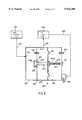
- FIG. 2is a diagrammatic view of the modified support portion of the invention showing how a specific support region for supporting the heel region is created that taps fluid from at least one support region other than the heel support region;
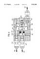
- FIG. 3is a detailed axial and longitudinal section view showing the operating principle of a currently preferred embodiment of a pressure-regulating valve of the invention connected between the main support region excluding the heel support region, and the heel support region; and
- FIG. 4is an axial and longitudinal section view of a practical embodiment of a pressure-regulating valve whose operating principle is shown in FIG. 3.
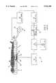
- This support apparatusmakes it possible to support an element, in particular the body of a patient P, as shown.
- the apparatus 10includes a support device proper 12, e.g. a mattress, comprising at least one closed or controlled-release chamber 14 that is flexible and inflatable.
- the chambermay be composed of a multitude of inflatable tubes that communicate with one another, said chamber 14 being inflatable under an adjustable predetermined initial inflation pressure.
- the chamber 14has a top face 15 serving to support the element to be supported P, and a bottom face 16 which may, for example, rest on a base (not shown) or on equivalent means.
- the apparatusfurther includes servo-control means 18 for servo-controlling the pressure at which the chamber 14 is filled as a function of the distance to which the element being supported penetrates into the support device.
- said servo-control meansmay comprise filling means 20, such as pumping means 20 for pumping a flow of fluid into the chamber 14, e.g. a gas, in particular air, or a liquid, in particular water, and they may include emptying means such as a valve 22.
- filling means 20such as pumping means 20 for pumping a flow of fluid into the chamber 14, e.g. a gas, in particular air, or a liquid, in particular water, and they may include emptying means such as a valve 22.
- the apparatusalso includes measurement means 30 for measuring the distance D between the top face 15 of the chamber and its bottom face 16.
- the measurement means 30may include a metal element 32, advantageously in the form of a piece of thin foil, secured to the top face 15 of the chamber 14, in this example inside said chamber 14, and cooperating with at least one inductive element 34 forming a position detector secured to the bottom face 16 of said chamber 14, which inductive element may be disposed inside the chamber, integrated into the bottom face of the chamber 14, or else it may be secured to the outside of the bottom face 16 of the chamber 14, as shown.
- a metal element 32advantageously in the form of a piece of thin foil, secured to the top face 15 of the chamber 14, in this example inside said chamber 14, and cooperating with at least one inductive element 34 forming a position detector secured to the bottom face 16 of said chamber 14, which inductive element may be disposed inside the chamber, integrated into the bottom face of the chamber 14, or else it may be secured to the outside of the bottom face 16 of the chamber 14, as shown.
- the apparatusalso includes control means 40 that act on the servo-control means 18 for servo-controlling the inflation pressure of the chamber 14 to ensure that, while the element is being supported, the distance D as measured between the top face 15 and the bottom face 16 of the chamber 14 is kept preferably at a predetermined distance value, e.g. an essentially constant value, i.e. a value essentially equal to a reference distance D c , or within an acceptable range of variation thereabout.
- a predetermined distance valuee.g. an essentially constant value, i.e. a value essentially equal to a reference distance D c , or within an acceptable range of variation thereabout.
- the control means 40may advantageously include a control station 42 comprising an electronic or an electro-mechanical central processing unit having a memory, which unit continuously or intermittently receives signals that are proportional to the measured distance value D m as transmitted by the above-mentioned measurement means 30, and compares the measured distance values D m with the reference distance value D c .
- the control station 42controls the servo-control means 20, 22 for servo-controlling the inflation pressure of the chamber 14 so that a measured distance D m is obtained that is essentially constantly equal to the reference distance D c or within an acceptable range of variation thereabout.
- the control means 40may include an oscillator device 44 described in the assignee's prior application and coupled to the inductive element 34, such as an induction coil, an amplifier device 46 whose gain may be adjusted by a reference setting device 48 defining the reference distance D c .
- the amplifier 46is then coupled to a proportional-plus-integral regulator device 50 coupled to a matching device 52 whose output is coupled to the control station 42.
- the inductive element 34such as an induction coil
- the inductive element 34is, for example, disposed on a reinforcing member 36 in the vicinity of that region of the element being supported P which has the largest mass or which is most protuberant, namely the sacral region of the patient P in this example, as explained in the assignee's above-mentioned prior document.
- the apparatusis modified so that the support device, e.g. a mattress, is subdivided into at least two support regions, including a support region specifically for supporting the heel region.
- the support devicee.g. a mattress
- the support deviceis subdivided into at least two support regions, including a support region specifically for supporting the heel region.
- each of the support regions 514, 514amay be made up of a plurality of inflatable tubes.
- the first support region or main region 514which may naturally be subdivided into a plurality of regions, may be inflated under an adjustable predetermined initial inflation pressure as in the structure shown in accompanying FIG. 1, briefly summarized above, and described in full detail in the assignee's previous document.
- the second support region 514a for supporting the heel regionis connected so that it taps fluid from the first support region via link means 600.
- the link means 600are preferably constituted by a pressure-regulating valve 610 having its inlet fed via a feed pipe 612 communicating with the main support region 514, and its outlet communicating with the heel or second support region 514a via a pipe 660.
- FIG. 3is a block diagram of the main support region 514 and of the heel region support region 514a, together with the inlet pipe 612 and the outlet pipe 660.
- the regulating valve 610includes an admission chamber 614 having an inlet 616 communicating with the inlet pipe 612 and an outlet 618 communicating with a pressure-regulating chamber 620 whose outlet 622 communicates with the outlet pipe 660 communicating with the second support region 514a.
- the valve 610also includes an independent damping chamber 630 separated from the pressure-regulating chamber 620 by a moving partition 632 supporting a piston 634 for closing off an orifice 636 providing communication between the admission chamber 614 and the pressure-regulating chamber 620.
- the admission chamber 614 and the pressure-regulating chamber 620further communicate with each other continuously via a calibrated orifice 640.
- the damping chamber 630also communicates continuously with the outside via a calibrated orifice 642.
- the second support region 514a for supporting the heel region Tcommunicates continuously with the outside via a calibrated orifice 650 which, to simplify matters, may be included in the regulating valve 610 as shown, and connected to the second support region 514a via a pipe 652.
- the pressure value at which the piston 634 closes off the orifice 636may be adjusted by providing adjustment means 670 for adjusting the pressure force acting against the rod 634a of the piston 634 so that the head 634b of the piston 634 closes off the orifice 636 at a given pressure value only.
- adjustment means 670may, for example, comprise a resilient element 672 exerting one-way pressure against the rod 634a of the piston 634, the unilateral pressure value of the resilient element being adjusted by a pressure adjustment member proper 674 such as a pressure calibration nut and screw system.
- the first support region 514which in this example supports the main portion of the body of the patient P, with the exception of the heel region T, is inflated by using a procedure identical to that described with reference to FIG. 1 of the assignee's prior document.
- the first support region 514Once the first support region 514 has been inflated to a certain pressure value, it feeds firstly, via the pipe 612, the admission chamber 614 and then the pressure-regulating chamber 620, and finally, via the pipe 660, the second support region 514a for supporting the heel region T. Above a certain pressure value, a leak is produced via the pipe 652 and via the calibrated orifice 650 for leakage.
- this calibrated orifice 650is small enough for the second support region 514a to take a relatively long period of time to deflate. Since the orifice 636 is much larger, and is fed to a greater extent via the pipe 612 from the first support region 514, the second support region 514a is inflated until the pressure in the admission chamber 614 reaches a value that is greater than the calibration pressure exerted by the pressure adjustment means 670, whereupon the head 634b of the piston 634 bears against the orifice 636 which is sealed by means of a sealing gasket 637.
- the pressure-regulating chamber 620is maintained at essentially constant pressure because of the existence of the fluid orifice 640 via which the admission chamber 614 communicates with the pressure-regulating chamber 620, and which substantially exactly compensates for the continuous leak obtained via the fluid orifice 650 at the outlet of the second support region 514a for supporting the heel region.
- the existence of the leakage orifice 642 via which the damping chamber 630 communicates with the outsidefacilitates proper operation of the moving partition 632, e.g. formed by a flexible membrane, e.g. made of a rubber or an equivalent material.
- This structuremakes it particularly simple to adjust the pressure in the second support region 514a for supporting the heel region T to a pressure value that is not more than the pressure value in the first support region 514, or to an adjustable fraction thereof.
- first support region 514with a regulating valve 522 similar to the valve 22 (FIG. 1) and controlled by the control station 42 so that the first support region 514 operates in accordance with the method and apparatus described with reference to FIG. 1 in the assignee's prior document, which method and apparatus are not modified.
- the present inventionmakes it possible to create a specific heel region whose pressure is made specific by very simple means, i.e. by tapping fluid from the first support region.
- the pressureit is possible to cause the pressure to vary as a function of the relative position of the patient on the support, of the patient's weight, and of the patient's morphology, or else as a function of the particular needs of the treatment.
- a preferred application of the inventionis thus to preventing or treating bedsores.
Landscapes
- Health & Medical Sciences (AREA)
- Nursing (AREA)
- Life Sciences & Earth Sciences (AREA)
- Animal Behavior & Ethology (AREA)
- General Health & Medical Sciences (AREA)
- Public Health (AREA)
- Veterinary Medicine (AREA)
- Invalid Beds And Related Equipment (AREA)
- Orthopedics, Nursing, And Contraception (AREA)
- Accommodation For Nursing Or Treatment Tables (AREA)
- Mattresses And Other Support Structures For Chairs And Beds (AREA)
Abstract
Description
Claims (40)
Applications Claiming Priority (2)
| Application Number | Priority Date | Filing Date | Title |
|---|---|---|---|
| FR9609204AFR2751530B1 (en) | 1996-07-23 | 1996-07-23 | METHOD AND DEVICE FOR SUPPORTING A PATIENT WITH A DERIVED SUPPORT HEEL AREA |
| FR96.09204 | 1996-07-23 |
Publications (1)
| Publication Number | Publication Date |
|---|---|
| US5934280Atrue US5934280A (en) | 1999-08-10 |
Family
ID=9494338
Family Applications (1)
| Application Number | Title | Priority Date | Filing Date |
|---|---|---|---|
| US08/896,612Expired - LifetimeUS5934280A (en) | 1996-07-23 | 1997-07-18 | Method and a device having a tap-fed heel support region |
Country Status (11)
| Country | Link |
|---|---|
| US (1) | US5934280A (en) |
| EP (1) | EP0959737B1 (en) |
| JP (1) | JP2000514686A (en) |
| AT (1) | ATE199819T1 (en) |
| AU (1) | AU3774597A (en) |
| BR (1) | BR9710741A (en) |
| CA (1) | CA2258116C (en) |
| DE (1) | DE69704379T2 (en) |
| ES (1) | ES2157591T3 (en) |
| FR (1) | FR2751530B1 (en) |
| WO (1) | WO1998003102A1 (en) |
Cited By (32)
| Publication number | Priority date | Publication date | Assignee | Title |
|---|---|---|---|---|
| US6079068A (en)* | 1996-12-23 | 2000-06-27 | Support Systems International Industries | Method and apparatus for supporting an element to be supported, in particular the body of a patient, the apparatus having a support device independent from the control device |
| US6212714B1 (en)* | 1995-01-03 | 2001-04-10 | Hill-Rom, Inc. | Hospital bed and mattress having a retracting foot section |
| US6244272B1 (en) | 1996-07-24 | 2001-06-12 | Support Systems International Industries | Multilayer assembly with a central electrically conductive layer for use as an inductive sensor element |
| US6505368B1 (en)* | 1999-07-06 | 2003-01-14 | Hill-Rom Services, Inc. | Mattress assembly |
| US6611979B2 (en) | 1997-09-23 | 2003-09-02 | Hill-Rom Services, Inc. | Mattress having a retractable foot section |
| US20030208848A1 (en)* | 2002-02-28 | 2003-11-13 | Flick Roland E. | Self-adjusting cushioning device |
| US6658827B2 (en) | 2001-08-15 | 2003-12-09 | Alan W. Brownlie | Interface pads |
| US6721980B1 (en) | 1998-10-28 | 2004-04-20 | Hill-Fom Services, Inc. | Force optimization surface apparatus and method |
| US20040244340A1 (en)* | 2001-08-15 | 2004-12-09 | Brownlie Alan W. | Interface pads with proportional valves |
| US20060168736A1 (en)* | 2004-04-30 | 2006-08-03 | Meyer Eric R | Pressure relief surface |
| US7296312B2 (en) | 2002-09-06 | 2007-11-20 | Hill-Rom Services, Inc. | Hospital bed |
| US20080201858A1 (en)* | 2007-02-27 | 2008-08-28 | Jean-Luc Caminade | Mattress type support device including at least one solenoid valve for controlling fluid feed/vent to or from compartments of the mattress |
| US20080263763A1 (en)* | 2007-04-25 | 2008-10-30 | Mary Butler | Patient support including turn assist, low air loss, or integrated lateral transfer |
| US20090217460A1 (en)* | 2005-07-08 | 2009-09-03 | Bobey John A | Patient support |
| US7698765B2 (en) | 2004-04-30 | 2010-04-20 | Hill-Rom Services, Inc. | Patient support |
| US20100101022A1 (en)* | 2008-10-24 | 2010-04-29 | Carl William Riley | Apparatuses for supporting and monitoring a person |
| US20110047709A1 (en)* | 2009-08-31 | 2011-03-03 | Jean-Francois Tarsaud | Support device with adjustable length and width |
| US20110068928A1 (en)* | 2009-09-18 | 2011-03-24 | Riley Carl W | Sensor control for apparatuses for supporting and monitoring a person |
| US8104122B2 (en) | 2005-12-19 | 2012-01-31 | Hill-Rom Services, Inc. | Patient support having an extendable foot section |
| USRE43155E1 (en)* | 1995-01-03 | 2012-02-07 | Hill-Rom Services, Inc. | Hospital bed and mattress having a retractable foot section |
| US8286282B2 (en) | 1995-08-04 | 2012-10-16 | Hill-Rom Services, Inc. | Bed frame and mattress synchronous control |
| US20140059781A1 (en)* | 2012-09-05 | 2014-03-06 | Stryker Corporation | Inflatable mattress and control methods |
| US8752220B2 (en) | 2009-07-10 | 2014-06-17 | Hill-Rom Services, Inc. | Systems for patient support, monitoring and treatment |
| US8844073B2 (en) | 2010-06-07 | 2014-09-30 | Hill-Rom Services, Inc. | Apparatus for supporting and monitoring a person |
| US9089459B2 (en) | 2013-11-18 | 2015-07-28 | Völker GmbH | Person support apparatus |
| US9165449B2 (en) | 2012-05-22 | 2015-10-20 | Hill-Rom Services, Inc. | Occupant egress prediction systems, methods and devices |
| US9333136B2 (en) | 2013-02-28 | 2016-05-10 | Hill-Rom Services, Inc. | Sensors in a mattress cover |
| US9552460B2 (en) | 2009-09-18 | 2017-01-24 | Hill-Rom Services, Inc. | Apparatus for supporting and monitoring a person |
| US9861550B2 (en) | 2012-05-22 | 2018-01-09 | Hill-Rom Services, Inc. | Adverse condition detection, assessment, and response systems, methods and devices |
| US11109799B2 (en) | 2017-10-24 | 2021-09-07 | Hill-Rom Services, Inc. | Modular turn assist apparatus and method therefor |
| US11357683B2 (en) | 2005-07-08 | 2022-06-14 | Hill-Rom Services, Inc. | Foot zone of a mattress |
| US12042453B2 (en) | 2019-02-26 | 2024-07-23 | Hill-Rom Services, Inc. | Patient positioning apparatus and mattress |
Families Citing this family (1)
| Publication number | Priority date | Publication date | Assignee | Title |
|---|---|---|---|---|
| FR2814062B1 (en)* | 2000-09-15 | 2008-06-06 | Jean Jacques Maurice | METHOD AND DEVICE FOR ADAPTING INTERFACE PRESSURE BETWEEN PATIENT AND INFLATABLE MEDIUM |
Citations (6)
| Publication number | Priority date | Publication date | Assignee | Title |
|---|---|---|---|---|
| GB1601808A (en)* | 1978-03-17 | 1981-11-04 | Watkins & Watson Ltd | Automatic compensator valve |
| US5086529A (en)* | 1990-07-25 | 1992-02-11 | Degroot Linda J | Segmented support article |
| US5168589A (en)* | 1989-04-17 | 1992-12-08 | Kinetic Concepts, Inc. | Pressure reduction air mattress and overlay |
| US5249318A (en)* | 1988-05-24 | 1993-10-05 | Loadsman Gerald H | Air support cushion |
| US5272778A (en)* | 1989-01-25 | 1993-12-28 | The Mediscus Group Inc. | Valve useful in low air loss beds |
| EP0676158A1 (en)* | 1994-04-06 | 1995-10-11 | Support Systems International Industries | Method and device for supporting the body of a patient allowing controlled sagging |
- 1996
- 1996-07-23FRFR9609204Apatent/FR2751530B1/ennot_activeExpired - Fee Related
- 1997
- 1997-07-18AUAU37745/97Apatent/AU3774597A/ennot_activeAbandoned
- 1997-07-18BRBR9710741Apatent/BR9710741A/ennot_activeIP Right Cessation
- 1997-07-18ESES97934593Tpatent/ES2157591T3/ennot_activeExpired - Lifetime
- 1997-07-18DEDE69704379Tpatent/DE69704379T2/ennot_activeExpired - Fee Related
- 1997-07-18ATAT97934593Tpatent/ATE199819T1/ennot_activeIP Right Cessation
- 1997-07-18WOPCT/FR1997/001341patent/WO1998003102A1/enactiveIP Right Grant
- 1997-07-18JPJP10506649Apatent/JP2000514686A/enactivePending
- 1997-07-18CACA002258116Apatent/CA2258116C/ennot_activeExpired - Fee Related
- 1997-07-18USUS08/896,612patent/US5934280A/ennot_activeExpired - Lifetime
- 1997-07-18EPEP97934593Apatent/EP0959737B1/ennot_activeExpired - Lifetime
Patent Citations (6)
| Publication number | Priority date | Publication date | Assignee | Title |
|---|---|---|---|---|
| GB1601808A (en)* | 1978-03-17 | 1981-11-04 | Watkins & Watson Ltd | Automatic compensator valve |
| US5249318A (en)* | 1988-05-24 | 1993-10-05 | Loadsman Gerald H | Air support cushion |
| US5272778A (en)* | 1989-01-25 | 1993-12-28 | The Mediscus Group Inc. | Valve useful in low air loss beds |
| US5168589A (en)* | 1989-04-17 | 1992-12-08 | Kinetic Concepts, Inc. | Pressure reduction air mattress and overlay |
| US5086529A (en)* | 1990-07-25 | 1992-02-11 | Degroot Linda J | Segmented support article |
| EP0676158A1 (en)* | 1994-04-06 | 1995-10-11 | Support Systems International Industries | Method and device for supporting the body of a patient allowing controlled sagging |
Cited By (87)
| Publication number | Priority date | Publication date | Assignee | Title |
|---|---|---|---|---|
| US7523515B2 (en) | 1995-01-03 | 2009-04-28 | Hill-Rom Services, Inc. | Hospital bed and mattress having a retractable foot section |
| USRE43155E1 (en)* | 1995-01-03 | 2012-02-07 | Hill-Rom Services, Inc. | Hospital bed and mattress having a retractable foot section |
| US20060096030A1 (en)* | 1995-01-03 | 2006-05-11 | Allen E D | Hospital bed and mattress having a retractable foot section |
| US7216384B2 (en) | 1995-01-03 | 2007-05-15 | Hill-Rom Services, Inc. | Hospital bed and mattress having a retractable foot section |
| US6496993B2 (en) | 1995-01-03 | 2002-12-24 | Hill-Rom Services, Inc. | Hospital bed and mattress having a retracting foot section |
| US6212714B1 (en)* | 1995-01-03 | 2001-04-10 | Hill-Rom, Inc. | Hospital bed and mattress having a retracting foot section |
| US20040221391A1 (en)* | 1995-01-03 | 2004-11-11 | Allen E. David | Hospital bed and matress having a retractable foot section |
| US7000272B2 (en) | 1995-01-03 | 2006-02-21 | Hill-Rom Services, Inc. | Hospital bed and mattress having a retractable foot section |
| US6684427B2 (en) | 1995-01-03 | 2004-02-03 | Hill-Rom Services, Inc. | Hospital bed and matress having a retractable foot section |
| US8286282B2 (en) | 1995-08-04 | 2012-10-16 | Hill-Rom Services, Inc. | Bed frame and mattress synchronous control |
| US6244272B1 (en) | 1996-07-24 | 2001-06-12 | Support Systems International Industries | Multilayer assembly with a central electrically conductive layer for use as an inductive sensor element |
| US6079068A (en)* | 1996-12-23 | 2000-06-27 | Support Systems International Industries | Method and apparatus for supporting an element to be supported, in particular the body of a patient, the apparatus having a support device independent from the control device |
| US6385803B1 (en) | 1996-12-23 | 2002-05-14 | Hill-Rom Industries S.A. | Method and apparatus for supporting an element to be support, in particular the body of a patient, the apparatus having a support device independent from the control device |
| US6611979B2 (en) | 1997-09-23 | 2003-09-02 | Hill-Rom Services, Inc. | Mattress having a retractable foot section |
| US6721980B1 (en) | 1998-10-28 | 2004-04-20 | Hill-Fom Services, Inc. | Force optimization surface apparatus and method |
| US8031080B2 (en) | 1998-10-28 | 2011-10-04 | Hill-Rom Services, Inc. | Patient support surface with vital signs sensors |
| US7515059B2 (en) | 1998-10-28 | 2009-04-07 | Hill-Rom Services, Inc. | Patient support surface with physiological sensors |
| US20090183312A1 (en)* | 1998-10-28 | 2009-07-23 | Price James H | Patient support surface with vital signs sensors |
| US20080060138A1 (en)* | 1998-10-28 | 2008-03-13 | Price James H | Patient support surface with physiological sensors |
| US7330127B2 (en) | 1998-10-28 | 2008-02-12 | Hill-Rom Services, Inc. | Force optimization surface apparatus and method |
| US20040194220A1 (en)* | 1998-10-28 | 2004-10-07 | Hill-Rom Services, Inc. | Force optimization surface apparatus and method |
| US6684434B2 (en) | 1999-07-06 | 2004-02-03 | Hill-Rom Services, Inc. | Mattress assembly |
| US6505368B1 (en)* | 1999-07-06 | 2003-01-14 | Hill-Rom Services, Inc. | Mattress assembly |
| US20040034936A1 (en)* | 1999-12-29 | 2004-02-26 | Hill-Rom Services, Inc. | Patient support |
| US9009893B2 (en) | 1999-12-29 | 2015-04-21 | Hill-Rom Services, Inc. | Hospital bed |
| US10251797B2 (en) | 1999-12-29 | 2019-04-09 | Hill-Rom Services, Inc. | Hospital bed |
| US6880189B2 (en) | 1999-12-29 | 2005-04-19 | Hill-Rom Services, Inc. | Patient support |
| US7137236B2 (en) | 2001-08-15 | 2006-11-21 | Brownlie Alan W | Interface pads with proportional valves |
| US6658827B2 (en) | 2001-08-15 | 2003-12-09 | Alan W. Brownlie | Interface pads |
| US20040244340A1 (en)* | 2001-08-15 | 2004-12-09 | Brownlie Alan W. | Interface pads with proportional valves |
| US6813790B2 (en) | 2002-02-28 | 2004-11-09 | Gaymar Industries, Inc. | Self-adjusting cushioning device |
| US20030208848A1 (en)* | 2002-02-28 | 2003-11-13 | Flick Roland E. | Self-adjusting cushioning device |
| US7669263B2 (en) | 2002-09-06 | 2010-03-02 | Hill-Rom Services, Inc. | Mattress assembly including adjustable length foot |
| US7520006B2 (en) | 2002-09-06 | 2009-04-21 | Hill-Rom Services, Inc. | Hospital bed including moveable foot portion |
| US7506390B2 (en) | 2002-09-06 | 2009-03-24 | Hill-Rom Services, Inc. | Patient support apparatus having controller area network |
| USRE43532E1 (en) | 2002-09-06 | 2012-07-24 | Hill-Rom Services, Inc. | Hospital bed |
| US7296312B2 (en) | 2002-09-06 | 2007-11-20 | Hill-Rom Services, Inc. | Hospital bed |
| US7703158B2 (en) | 2002-09-06 | 2010-04-27 | Hill-Rom Services, Inc. | Patient support apparatus having a diagnostic system |
| US7406731B2 (en) | 2002-09-06 | 2008-08-05 | Holl-Rom Services, Inc. | Hospital bed |
| US7698765B2 (en) | 2004-04-30 | 2010-04-20 | Hill-Rom Services, Inc. | Patient support |
| US8196240B2 (en) | 2004-04-30 | 2012-06-12 | Hill-Rom Services, Inc. | Pressure relief surface |
| US8146191B2 (en) | 2004-04-30 | 2012-04-03 | Hill-Rom Services, Inc. | Patient support |
| US7469436B2 (en) | 2004-04-30 | 2008-12-30 | Hill-Rom Services, Inc. | Pressure relief surface |
| US20060168736A1 (en)* | 2004-04-30 | 2006-08-03 | Meyer Eric R | Pressure relief surface |
| US7937791B2 (en) | 2004-04-30 | 2011-05-10 | Hill-Rom Services, Inc. | Pressure relief surface |
| US11357683B2 (en) | 2005-07-08 | 2022-06-14 | Hill-Rom Services, Inc. | Foot zone of a mattress |
| US20090217460A1 (en)* | 2005-07-08 | 2009-09-03 | Bobey John A | Patient support |
| US10507147B2 (en) | 2005-07-08 | 2019-12-17 | Hill-Rom Services, Inc. | Patient support |
| US9707141B2 (en) | 2005-07-08 | 2017-07-18 | Hill-Rom Services, Inc. | Patient support |
| US8104122B2 (en) | 2005-12-19 | 2012-01-31 | Hill-Rom Services, Inc. | Patient support having an extendable foot section |
| US20080201858A1 (en)* | 2007-02-27 | 2008-08-28 | Jean-Luc Caminade | Mattress type support device including at least one solenoid valve for controlling fluid feed/vent to or from compartments of the mattress |
| US7712171B2 (en) | 2007-04-25 | 2010-05-11 | Hill-Rom Services, Inc. | Patient support including turn assist, low air loss, or integrated lateral transfer |
| US20080263763A1 (en)* | 2007-04-25 | 2008-10-30 | Mary Butler | Patient support including turn assist, low air loss, or integrated lateral transfer |
| US20100101022A1 (en)* | 2008-10-24 | 2010-04-29 | Carl William Riley | Apparatuses for supporting and monitoring a person |
| US8281433B2 (en) | 2008-10-24 | 2012-10-09 | Hill-Rom Services, Inc. | Apparatuses for supporting and monitoring a person |
| US8752220B2 (en) | 2009-07-10 | 2014-06-17 | Hill-Rom Services, Inc. | Systems for patient support, monitoring and treatment |
| US20110047709A1 (en)* | 2009-08-31 | 2011-03-03 | Jean-Francois Tarsaud | Support device with adjustable length and width |
| US20110068928A1 (en)* | 2009-09-18 | 2011-03-24 | Riley Carl W | Sensor control for apparatuses for supporting and monitoring a person |
| US9775758B2 (en) | 2009-09-18 | 2017-10-03 | Hill-Rom Services, Inc. | Person support apparatus having physiological sensor |
| US9013315B2 (en) | 2009-09-18 | 2015-04-21 | Hill-Rom Services, Inc. | Sensor control for apparatuses for supporting and monitoring a person |
| US9044204B2 (en) | 2009-09-18 | 2015-06-02 | Hill-Rom Services, Inc. | Apparatuses for supporting and monitoring a condition of a person |
| US20110068935A1 (en)* | 2009-09-18 | 2011-03-24 | Riley Carl W | Apparatuses for supporting and monitoring a condition of a person |
| US10583058B2 (en) | 2009-09-18 | 2020-03-10 | Hill-Rom Services, Inc. | Person support apparatus having physiological sensor |
| US8525679B2 (en) | 2009-09-18 | 2013-09-03 | Hill-Rom Services, Inc. | Sensor control for apparatuses for supporting and monitoring a person |
| US8525680B2 (en) | 2009-09-18 | 2013-09-03 | Hill-Rom Services, Inc. | Apparatuses for supporting and monitoring a condition of a person |
| US9549705B2 (en) | 2009-09-18 | 2017-01-24 | Hill-Rom Services, Inc. | Apparatuses for supporting and monitoring a condition of a person |
| US10111794B2 (en) | 2009-09-18 | 2018-10-30 | Hill-Rom Services, Inc. | Person support apparatus having physiological sensor |
| US9552460B2 (en) | 2009-09-18 | 2017-01-24 | Hill-Rom Services, Inc. | Apparatus for supporting and monitoring a person |
| US9549675B2 (en) | 2009-09-18 | 2017-01-24 | Hill-Rom Services, Inc. | Sensor control for apparatuses for supporting and monitoring a person |
| US8844073B2 (en) | 2010-06-07 | 2014-09-30 | Hill-Rom Services, Inc. | Apparatus for supporting and monitoring a person |
| US9761109B2 (en) | 2012-05-22 | 2017-09-12 | Hill-Rom Services, Inc. | Occupant egress prediction systems, methods and devices |
| US9861550B2 (en) | 2012-05-22 | 2018-01-09 | Hill-Rom Services, Inc. | Adverse condition detection, assessment, and response systems, methods and devices |
| US9978244B2 (en) | 2012-05-22 | 2018-05-22 | Hill-Rom Services, Inc. | Occupant falls risk determination systems, methods and devices |
| US9552714B2 (en) | 2012-05-22 | 2017-01-24 | Hill-Rom Services, Inc. | Occupant egress prediction systems, methods and devices |
| US9165449B2 (en) | 2012-05-22 | 2015-10-20 | Hill-Rom Services, Inc. | Occupant egress prediction systems, methods and devices |
| US11413202B2 (en) | 2012-09-05 | 2022-08-16 | Stryker Corporation | Inflatable mattress and control methods |
| US20140059781A1 (en)* | 2012-09-05 | 2014-03-06 | Stryker Corporation | Inflatable mattress and control methods |
| US9468307B2 (en)* | 2012-09-05 | 2016-10-18 | Stryker Corporation | Inflatable mattress and control methods |
| US20170027792A1 (en)* | 2012-09-05 | 2017-02-02 | Stryker Corporation | Inflatable mattress and control methods |
| US10682273B2 (en)* | 2012-09-05 | 2020-06-16 | Stryker Corporation | Inflatable mattress and control methods |
| US12023287B2 (en) | 2012-09-05 | 2024-07-02 | Stryker Corporation | Inflatable mattress and control methods |
| US9333136B2 (en) | 2013-02-28 | 2016-05-10 | Hill-Rom Services, Inc. | Sensors in a mattress cover |
| US11684529B2 (en) | 2013-02-28 | 2023-06-27 | Hill-Rom Services, Inc. | Mattress cover sensor method |
| US9089459B2 (en) | 2013-11-18 | 2015-07-28 | Völker GmbH | Person support apparatus |
| US11872052B2 (en) | 2017-10-24 | 2024-01-16 | Hill-Rom Services, Inc. | Modular turn assist apparatus and method therefor |
| US11109799B2 (en) | 2017-10-24 | 2021-09-07 | Hill-Rom Services, Inc. | Modular turn assist apparatus and method therefor |
| US12042453B2 (en) | 2019-02-26 | 2024-07-23 | Hill-Rom Services, Inc. | Patient positioning apparatus and mattress |
Also Published As
| Publication number | Publication date |
|---|---|
| CA2258116C (en) | 2006-06-06 |
| ATE199819T1 (en) | 2001-04-15 |
| DE69704379T2 (en) | 2004-02-05 |
| CA2258116A1 (en) | 1998-01-29 |
| FR2751530A1 (en) | 1998-01-30 |
| EP0959737B1 (en) | 2001-03-21 |
| WO1998003102A1 (en) | 1998-01-29 |
| ES2157591T3 (en) | 2001-08-16 |
| AU3774597A (en) | 1998-02-10 |
| JP2000514686A (en) | 2000-11-07 |
| EP0959737A1 (en) | 1999-12-01 |
| FR2751530B1 (en) | 1998-10-23 |
| DE69704379D1 (en) | 2001-04-26 |
| BR9710741A (en) | 1999-08-17 |
Similar Documents
| Publication | Publication Date | Title |
|---|---|---|
| US5934280A (en) | Method and a device having a tap-fed heel support region | |
| EP0812555B1 (en) | Pressure control assembly for an air mattress | |
| US6427538B1 (en) | Electronic control system for a variable support mechanism | |
| US6009580A (en) | Method and apparatus for supporting an element to be supported, in particular the body of a patient, making it possible to support said element at a predetermined float line | |
| US6148461A (en) | Inflatable support | |
| KR100730803B1 (en) | Inflatable support | |
| US5963997A (en) | Low air loss patient support system providing active feedback pressure sensing and correction capabilities for use as a bed mattress and a wheelchair seating system | |
| US8087113B2 (en) | Inflatable support | |
| US6094762A (en) | Method and apparatus for supporting an element to be supported, in particular the body of a patient, and having an integrated system for achieving pressure equilibrium dynamically and automatically | |
| US5560374A (en) | Patient support apparatus and method | |
| US5061242A (en) | Adjustable implantable drug infusion system | |
| US5052067A (en) | Bimodal system for pressurizing a low air loss patient support | |
| US5073999A (en) | Method for turning a patient with a low air loss patient support | |
| US5062167A (en) | Bimodal turning method | |
| AU681084B2 (en) | Improvements in or relating to air support systems | |
| GB2103842A (en) | Pneumatic control system for a pressure wave device | |
| WO2001078539B1 (en) | Dynamically-controlled cushioning system for an article of footwear | |
| GB2380935A (en) | Inflatable mattress system and method of use thereof | |
| IE53665B1 (en) | Apparatus and method for applying a dynamic pressure wave to an extremity | |
| US5944066A (en) | Method and apparatus for rapidly inflating an inflatable chamber in particular a chamber of a support device such as a mattress | |
| US3782363A (en) | Pneumo-infufflator apparatus | |
| US5065466A (en) | Quick disconnect coupling for a low air loss patient support | |
| EP1482891B1 (en) | Inflatable support | |
| EP0482267A1 (en) | Method for weighing human body and the like | |
| CA1178500A (en) | Apparatus and method for pneumatically controlling a dynamic pressure wave device |
Legal Events
| Date | Code | Title | Description |
|---|---|---|---|
| AS | Assignment | Owner name:SUPPORT SYSTEMS INTERNATIONAL INDUSTRIES, FRANCE Free format text:ASSIGNMENT OF ASSIGNORS INTEREST;ASSIGNORS:VIARD, JEAN-LOUIS;CAMUS, GILLES;REEL/FRAME:009065/0763 Effective date:19970623 | |
| STCF | Information on status: patent grant | Free format text:PATENTED CASE | |
| FEPP | Fee payment procedure | Free format text:PAYOR NUMBER ASSIGNED (ORIGINAL EVENT CODE: ASPN); ENTITY STATUS OF PATENT OWNER: LARGE ENTITY | |
| AS | Assignment | Owner name:HILL-ROM INDUSTRIES S.A., FRANCE Free format text:CHANGE OF NAME;ASSIGNOR:SUPPORT SYSTEMS INTERNATIONAL INDUSTRIES;REEL/FRAME:011019/0588 Effective date:19990430 | |
| FEPP | Fee payment procedure | Free format text:PAYOR NUMBER ASSIGNED (ORIGINAL EVENT CODE: ASPN); ENTITY STATUS OF PATENT OWNER: LARGE ENTITY Free format text:PAYER NUMBER DE-ASSIGNED (ORIGINAL EVENT CODE: RMPN); ENTITY STATUS OF PATENT OWNER: LARGE ENTITY | |
| FEPP | Fee payment procedure | Free format text:PAYER NUMBER DE-ASSIGNED (ORIGINAL EVENT CODE: RMPN); ENTITY STATUS OF PATENT OWNER: LARGE ENTITY Free format text:PAYOR NUMBER ASSIGNED (ORIGINAL EVENT CODE: ASPN); ENTITY STATUS OF PATENT OWNER: LARGE ENTITY | |
| FEPP | Fee payment procedure | Free format text:PAYOR NUMBER ASSIGNED (ORIGINAL EVENT CODE: ASPN); ENTITY STATUS OF PATENT OWNER: LARGE ENTITY Free format text:PAYER NUMBER DE-ASSIGNED (ORIGINAL EVENT CODE: RMPN); ENTITY STATUS OF PATENT OWNER: LARGE ENTITY | |
| FPAY | Fee payment | Year of fee payment:4 | |
| FPAY | Fee payment | Year of fee payment:8 | |
| FPAY | Fee payment | Year of fee payment:12 |