US5934091A - Refrigerant recovery and recycling system - Google Patents
Refrigerant recovery and recycling systemDownload PDFInfo
- Publication number
- US5934091A US5934091AUS08/960,521US96052197AUS5934091AUS 5934091 AUS5934091 AUS 5934091AUS 96052197 AUS96052197 AUS 96052197AUS 5934091 AUS5934091 AUS 5934091A
- Authority
- US
- United States
- Prior art keywords
- refrigerant
- heat exchanger
- oil separator
- high pressure
- air conditioning
- Prior art date
- Legal status (The legal status is an assumption and is not a legal conclusion. Google has not performed a legal analysis and makes no representation as to the accuracy of the status listed.)
- Expired - Fee Related
Links
- 239000003507refrigerantSubstances0.000titleclaimsabstractdescription195
- 238000004064recyclingMethods0.000titleclaimsabstractdescription32
- 238000011084recoveryMethods0.000titleclaimsdescription28
- 238000004378air conditioningMethods0.000claimsabstractdescription47
- 239000007788liquidSubstances0.000claimsabstractdescription28
- 230000008016vaporizationEffects0.000claimsabstractdescription4
- 239000003921oilSubstances0.000claimsdescription120
- 238000005507sprayingMethods0.000claimsdescription4
- 239000010725compressor oilSubstances0.000claimsdescription3
- 238000000034methodMethods0.000abstractdescription12
- 238000000926separation methodMethods0.000abstractdescription8
- 239000002274desiccantSubstances0.000description6
- 239000000047productSubstances0.000description6
- 238000009833condensationMethods0.000description5
- 230000005494condensationEffects0.000description5
- 230000009977dual effectEffects0.000description5
- 239000012530fluidSubstances0.000description4
- 238000010438heat treatmentMethods0.000description4
- 238000012545processingMethods0.000description4
- 239000007921spraySubstances0.000description4
- XLYOFNOQVPJJNP-UHFFFAOYSA-NwaterSubstancesOXLYOFNOQVPJJNP-UHFFFAOYSA-N0.000description4
- CBENFWSGALASAD-UHFFFAOYSA-NOzoneChemical compound[O-][O+]=OCBENFWSGALASAD-UHFFFAOYSA-N0.000description3
- 230000008901benefitEffects0.000description3
- 239000000356contaminantSubstances0.000description3
- 230000000694effectsEffects0.000description3
- 238000001704evaporationMethods0.000description3
- 230000005484gravityEffects0.000description3
- 238000005057refrigerationMethods0.000description3
- -1CFC compoundsChemical class0.000description2
- 235000014676Phragmites communisNutrition0.000description2
- 238000013019agitationMethods0.000description2
- 230000007423decreaseEffects0.000description2
- 230000008020evaporationEffects0.000description2
- 239000011521glassSubstances0.000description2
- QSHDDOUJBYECFT-UHFFFAOYSA-NmercuryChemical compound[Hg]QSHDDOUJBYECFT-UHFFFAOYSA-N0.000description2
- 229910052753mercuryInorganic materials0.000description2
- 238000013022ventingMethods0.000description2
- 208000000453Skin NeoplasmsDiseases0.000description1
- 239000003570airSubstances0.000description1
- 238000006243chemical reactionMethods0.000description1
- KYKAJFCTULSVSH-UHFFFAOYSA-Nchloro(fluoro)methaneChemical classF[C]ClKYKAJFCTULSVSH-UHFFFAOYSA-N0.000description1
- 238000004891communicationMethods0.000description1
- 150000001875compoundsChemical class0.000description1
- 230000006835compressionEffects0.000description1
- 238000007906compressionMethods0.000description1
- 238000010276constructionMethods0.000description1
- 238000001816coolingMethods0.000description1
- 230000003247decreasing effectEffects0.000description1
- 230000000779depleting effectEffects0.000description1
- 230000005611electricityEffects0.000description1
- 230000005802health problemEffects0.000description1
- 230000002706hydrostatic effectEffects0.000description1
- 239000000463materialSubstances0.000description1
- 239000000203mixtureSubstances0.000description1
- 238000012986modificationMethods0.000description1
- 230000004048modificationEffects0.000description1
- 239000003960organic solventSubstances0.000description1
- 239000002244precipitateSubstances0.000description1
- 230000008569processEffects0.000description1
- 238000000746purificationMethods0.000description1
- 230000005855radiationEffects0.000description1
- 238000011160researchMethods0.000description1
- 230000000630rising effectEffects0.000description1
- 201000000849skin cancerDiseases0.000description1
- 238000012546transferMethods0.000description1
- 238000009834vaporizationMethods0.000description1
Images


Classifications
- B—PERFORMING OPERATIONS; TRANSPORTING
- B60—VEHICLES IN GENERAL
- B60H—ARRANGEMENTS OF HEATING, COOLING, VENTILATING OR OTHER AIR-TREATING DEVICES SPECIALLY ADAPTED FOR PASSENGER OR GOODS SPACES OF VEHICLES
- B60H1/00—Heating, cooling or ventilating [HVAC] devices
- B60H1/00507—Details, e.g. mounting arrangements, desaeration devices
- B60H1/00585—Means for monitoring, testing or servicing the air-conditioning
- F—MECHANICAL ENGINEERING; LIGHTING; HEATING; WEAPONS; BLASTING
- F25—REFRIGERATION OR COOLING; COMBINED HEATING AND REFRIGERATION SYSTEMS; HEAT PUMP SYSTEMS; MANUFACTURE OR STORAGE OF ICE; LIQUEFACTION SOLIDIFICATION OF GASES
- F25B—REFRIGERATION MACHINES, PLANTS OR SYSTEMS; COMBINED HEATING AND REFRIGERATION SYSTEMS; HEAT PUMP SYSTEMS
- F25B45/00—Arrangements for charging or discharging refrigerant
- F—MECHANICAL ENGINEERING; LIGHTING; HEATING; WEAPONS; BLASTING
- F25—REFRIGERATION OR COOLING; COMBINED HEATING AND REFRIGERATION SYSTEMS; HEAT PUMP SYSTEMS; MANUFACTURE OR STORAGE OF ICE; LIQUEFACTION SOLIDIFICATION OF GASES
- F25B—REFRIGERATION MACHINES, PLANTS OR SYSTEMS; COMBINED HEATING AND REFRIGERATION SYSTEMS; HEAT PUMP SYSTEMS
- F25B2345/00—Details for charging or discharging refrigerants; Service stations therefor
- F25B2345/002—Collecting refrigerant from a cycle
- F—MECHANICAL ENGINEERING; LIGHTING; HEATING; WEAPONS; BLASTING
- F25—REFRIGERATION OR COOLING; COMBINED HEATING AND REFRIGERATION SYSTEMS; HEAT PUMP SYSTEMS; MANUFACTURE OR STORAGE OF ICE; LIQUEFACTION SOLIDIFICATION OF GASES
- F25B—REFRIGERATION MACHINES, PLANTS OR SYSTEMS; COMBINED HEATING AND REFRIGERATION SYSTEMS; HEAT PUMP SYSTEMS
- F25B2345/00—Details for charging or discharging refrigerants; Service stations therefor
- F25B2345/005—Service stations therefor
- F25B2345/0052—Service stations therefor having wheels
- F—MECHANICAL ENGINEERING; LIGHTING; HEATING; WEAPONS; BLASTING
- F25—REFRIGERATION OR COOLING; COMBINED HEATING AND REFRIGERATION SYSTEMS; HEAT PUMP SYSTEMS; MANUFACTURE OR STORAGE OF ICE; LIQUEFACTION SOLIDIFICATION OF GASES
- F25B—REFRIGERATION MACHINES, PLANTS OR SYSTEMS; COMBINED HEATING AND REFRIGERATION SYSTEMS; HEAT PUMP SYSTEMS
- F25B2345/00—Details for charging or discharging refrigerants; Service stations therefor
- F25B2345/006—Details for charging or discharging refrigerants; Service stations therefor characterised by charging or discharging valves
Definitions
- the present inventionrelates to an apparatus and method for recovering and recycling refrigerant from an air conditioning unit; to a combined heat exchanger and oil separator and for use in an apparatus for recovering and recycling refrigerant from an air conditioning unit; and to a method for improving the efficiency of a combined oil separator and heat exchanger for use in an apparatus for recovering and recycling refrigerant from an air conditioning unit.
- CFCschlorofluorocarbon compounds
- refrigeranta working fluid
- CFCschlorofluorocarbon compounds
- the refrigerant in the equipmentmay eventually become contaminated with dirt, oil and/or moisture. These contaminants affect the efficiency of the equipment and may eventually lead to damage of the compressor and other components in the equipment.
- Refrigerant recovery and recycling systemsare described in, for example, U.S. Pat. Nos. 3,699,781; 4,285,206; 4,364,236; 4,805,416; 4,768,347; 4,809,520; 5,072,593; 5,245,840; 5,335,512; 4,809,520; 5,353,603; and 5,617,731.
- R-134a refrigerantMost automobile air conditioning units utilize either R-134a refrigerant or R-12 refrigerant.
- the R-12 refrigerantis often referred to as ozone depleting refrigerant and was commonly used in automobile systems until about the year 1993.
- Modem automobile systemsuse the R-134a refrigerant which is more environmentally friendly. Because of the use of different types of refrigerant, it is desirable to provide an apparatus that will recover and recycle each type of refrigerant.
- the inventionrelates to an apparatus for recovering and recycling refrigerants from an air conditioning unit.
- the apparatusincludes a contaminated refrigerant recovery line for conveying contaminated refrigerant, a combined oil separator and heat exchanger, a dryer for removal of moisture from vapor refrigerant, a compressor for compressing refrigerant, and a receiver tank for receiving condensed purified refrigerant.
- the combined oil separator and heat exchangerincludes a canister having a top wall, a bottom wall, and a substantially cylindrical side wall.
- the canisteradditionally includes a high pressure region and a low pressure region.
- the high pressure regionincludes heat exchange coils and has a high pressure inlet through the top wall for providing purified refrigerant vapor, and a high pressure outlet through the top wall for removing purified refrigerant liquid.
- the heat exchange coilsare provided in the lower region of the canister.
- the low pressure regionincludes a low pressure inlet through the bottom wall for introducing contaminated refrigerant proximate to heat exchange coils, and low pressure outlet through the top wall for removal of refrigerant vapor, and condensed oil outlet through the top wall for removal of condensed oil.
- the low pressure inletincludes an evaporator injector having a tube for conveying contaminated refrigerant inside the combined oil separator and heat exchanger, and orifices directed downward for spraying contaminated refrigerant onto the coils.
- the orificesare provided within about 5 inches of the coils, and more preferably within about 4 inches of the coils. It is an advantage of the present invention that the evaporator injector sprays the contaminated refrigerant onto the heat exchange coils in order to enhance the separation efficiency between the vapor refrigerant and the oil. By spraying the contaminated refrigerant onto the coils, enhanced agitation of fluid on the coils is provided resulting in increased heat transfer. Furthermore, the proximate location of the spray to the coils reduces the condensation problem associated with having cold liquid fall through vapor which accumulates in the upper region of the canister.
- the dryeris provided for removal of moisture from vapor refrigerant from the low pressure outlet of the combined oil separator and heat exchanger.
- the compressoris provided for compressing the purified refrigerant from the dryer to provide a warm, high pressure refrigerant line for feeding through the high pressure inlet in the combined oil separator and heat exchanger, and through the heat exchange coils.
- the receiver tankis provided for receiving condensed purified refrigerant from the high pressure outlet of the combined oil separator and heat exchanger.
- the inventionrelates to a method for recovering and recycling refrigerant from an air conditioning unit.
- the methodincludes steps of providing a source of contaminated refrigerant for conversion to purified refrigerant; introducing the contaminated refrigerant into a lower region of a combined oil separator and heat exchanger; feeding separated volatile component to a dryer for removal of moisture and to a compressor for compressing refrigerant from the dryer to provide compressed, purified refrigerant; and feeding the compressed, purified refrigerant from the compressor to the high pressure inlet in the combined oil separator and heat exchanger to provide a condensed refrigerant.
- the methodcan include a step of charging purified refrigerant into an automobile air conditioning unit.
- the inventionfurther relates to a combined oil separator and heat exchanger for use in an apparatus for recovering and recycling refrigerants from an air conditioning unit. It is this combined oil separator and heat exchanger which provides enhanced refrigerant and oil separation compared with prior art devices.
- the inventionrelates to a method for improving the efficiency of a combined oil separator and heat exchanger for use in an apparatus for recovering and recycling refrigerant from an air conditioning unit.
- FIG. 1shows a schematic representation of a dual refrigerant recovery and recycling system in accordance with the present invention
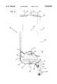
- FIG. 2shows a partial cutaway view of the heat exchanger unit in accordance with the present invention
- FIG. 3shows a sectional view of the heat exchanger unit shown in FIG. 2;
- FIG. 4shows a top view of the heat exchanger unit shown in FIG. 2;
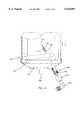
- FIG. 5shows a portable apparatus for recovering and recycling refrigerants according to the principles of the invention.
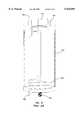
- FIG. 6shows a prior art recovery and separation tank for use in an apparatus for recovering and recycling refrigerants.
- FIG. 1a schematic representation of a single pass, dual refrigerant recovery and recycling system according to the present invention is provided at reference numeral 10.
- the system 10is referred to as single pass because the refrigerant passes through the system essentially once for purification, rather than being processed in a loop. The path of the refrigerant is indicated by the arrows.
- the system 10is referred to as a dual system because it provides for the recovery and recycling of two incompatible types of refrigerant.
- the systemcan be used to recover and recycle R-12 refrigerant and R-134a refrigerant from automobile air conditioning systems.
- FIG. 1shows a schematic of a system for recovering and recycling R-134a refrigerant from an automotive air conditioning system at reference numeral 11, and a schematic of a system for recovering and recycling R-12 refrigerant from an automotive refrigerant systems at reference numeral 11'.
- the steps and equipment provided for both systemscorrespond but may be different to reflect the different materials processed.
- the two types of refrigerantare incompatible and should not be mixed.
- the following description of the operation of the system 11generally refers to the system for recovering and recycling R-134a refrigerant, and it should be appreciated that the description applies to the system for recovering and recycling R-12 refrigerant wherein reference numeral are used with the prime designation to identify similar structure.
- the system 11includes a low pressure side hose 12 and a high pressure side hose 14 for connecting, via hose fittings 16, to the low pressure side and the high pressure side, respectively, of an automobile air conditioning unit.
- the hose fittingsinclude valves which, once attached to the appropriate port on the automobile air conditioning system, can be opened to provide flow therethrough.
- the hoses 12 and 14connect to a manifold set 18 having pressure gauges 20 for measuring the pressure in the low side hose 12 and the high side hose 14, and valves 22 for selectively opening and closing flow through the low side hose 12 and the high side hose 14.
- both valves 22are preferably open to allow contaminated refrigerant to drain more quickly.
- the refrigerant obtained from the automobile air conditioning unitis referred to as contaminated refrigerant because it is likely to include particulates, oil, water, and air which should be removed to a desired extent to provide purified refrigerant which can then be introduced back into the automobile air conditioning system.
- the refrigerantmay be referred to as the processing fluid.
- the symbols identified at reference numerals 23 and 25are meant to represent a port in the bulkhead where hoses can be connected and disconnected. As shown in FIG. 1, the components provided to the right side of bulkhead ports 23 and 25 in the system 11 are generally provided within a container and the components provided to the left of the bulkhead ports 23 and 25 are generally more accessible. The bulkhead ports 23 and 25 are identified in FIG. 5.
- the contaminated refrigerantpasses through the manifold set 18 and flows through the strainer 24 for removal of particulates.
- a commercially available strainer which can be used in this inventionis 10 ⁇ m strainer available from Parker, Inc.
- the refrigerantthen passes by vacuum switch 26 which senses the pressure in the line and activates the vacuum pump 28 when the pressure in the line decreases to 8 inches of mercury.
- the vacuum pump 28then runs for a predetermined amount of time in order to dry out and evacuate of the automobile air conditioning system.
- the refrigerantpasses from the strainer 24 through the recovery solenoid valve 30 and past the recovery check valve 32. While recovering contaminated refrigerant from the automobile air conditioning unit, the recovery solenoid valve 30 is opened and the charge solenoid valve 34 and the evacuate solenoid valve 36 are closed. This arrangement provides that the recovered refrigerant flows through the recovery solenoid valve 30 for processing.
- the recovery check valve 32is provided to ensure that the refrigerant does not flow in the reverse direction.
- the refrigerant recovered from the automobile air conditioning unitis likely to be a combination of gas and liquid.
- the refrigerantflows out of the automobile air conditioning unit under pressure, which causes the refrigerant to flow through the recovery system and into the combined oil separator and heat exchanger 40.
- the refrigerantenters the combined oil separator and heat exchanger 40 in the lower region 41 proximate the heat exchange coils 42.
- the heat exchange coils 42are warmer than the contaminated refrigerant entering via the line 38, resulting in heat transferring to the refrigerant and vaporization of the volatile components in the refrigerant.
- the oil contained within the refrigerantis not volatilized, and gravity causes the oil to settle in a puddle 43 in the lower region 41 of the combined oil separator and heat exchanger 40.
- the oil puddle 43is allowed to drain through the top of the combined oil separator and heat exchanger 40 via the oil drain line 44 which extends into the oil puddle 43.
- the valve 46is opened, pressure within the combined oil separator and heat exchanger 40 causes oil to rise through the oil recovery line 44 and into a container 212 for subsequent handling thereof.
- the valve 46is generally not opened until after the refrigerant recovery process is completed.
- the volatilized componentsgenerally include refrigerant and moisture, and pass via line 48 from the combined oil separator and heat exchanger 40 into the filter/dryer 50.
- the filter/dryeris preferably a desiccant filter which removes water from the refrigerant.
- a commercially available desiccant filter which can be used in the inventionis available from Alco, Inc.
- a sight glass 51can be provided for determining when it is appropriate to replace the desiccant filter. If the water concentration in the purified refrigerant is too high, the desiccant filter should be replaced. It is expected that the desiccant filter will be replaced after about 30 hours of operation or after having serviced about 150 automobile air conditioning units.
- the sight glass 51includes a moisture indicator 53 which shows a green color when the purified refrigerant is sufficiently moisture-free.
- the moisture indicator 53turns yellow, the water concentration in the purified refrigerant is too high, and the desiccant filter 50 should be replaced.
- the refrigerantleaves the filter/dryer 50 via line 52 as purified refrigerant and passes through the compressor 60.
- a commercially available compressor which can be used in this inventionis a 1/3 hp compressor. In general, it is expected that the compressor 60 will compress the purified refrigerant to a pressure of at least about 100 psi. While passing through the compressor 60, the purified refrigerant tends to pick up small amounts of oil from the compressor. In order to maintain proper functioning of the compressor 60, it is desirable to remove the oil from the refrigerant and return it to the compressor. This concept of returning oil to a compressor is certainly not new and commercially available oil separators have been sold for this purpose for several decades. One such company that provides compressor oil separators is Temprite, Inc.
- the combination of refrigerant and oilthen leaves the compressor 60 via line 62 under high pressure and enters the compressor oil separator 64. Once the high-pressure refrigerant containing small amounts of oil enters the oil separator 64, the oil precipitates out and collects at the bottom of the oil separator 64.
- An oil return line 66is provided for returning the oil to the compressor 60.
- the oil return solenoid valve 68opens in order to allow collected oil to flow from the oil separator 64 back to the compressor 60. Refrigerant then passes as a vapor out of the oil separator 64 via line 70 and through check valve 72. The check valve 72 prevents flow of refrigerant in the reverse direction.
- valve 68opens allowing oil which has collected in the bottom of the oil separator 64 to flow back into the compressor 60.
- Added benefits of opening the valve 68include equalizing the pressure on both sides of the compressor 60 which enhances subsequent start up. Furthermore, opening the valve 68 pressurizes the combined oil separator and heat exchanger 40 so that the puddle of oil 43 collected therein can be pushed out through the top via line 44.
- Previous commercially available oil separatorsrely upon gravity for removing oil by draining through a hole in the bottom. In contrast, the combined oil separator and heat exchanger of the present relies upon pressure for forcing the separated oil out the top.
- the high-pressure, purified refrigerant in line 70is generally in the vapor gaseous state and is relatively warm. In order to convert the gaseous refrigerant into a liquid, heat is removed therefrom. The vaporous refrigerant is then fed back through the combined oil separator and heat exchanger 40 within the heat exchange coils 42. As heat is transferred from the heat exchange coils 42 to the contaminated refrigerant, the refrigerant inside the heat exchange coils 42 condenses and flows out of the combined oil separator and heat exchanger 40 via line 76.
- the combined oil separator and heat exchanger 40performs the functions of an oil separator, a heat exchanger, and a condenser, which are components found in prior art refrigerant recovery and recycle systems.
- the refrigerant recovery and recycle system of the present inventionprovides for a system which does not include separate oil separator, heat exchanger, and condenser. Rather, all three are provided in the combined oil separator and heat exchanger 40.
- a high pressure cut off switch 74is provided in communication with line 70. If the pressure in line 70 is too high, the high pressure switch is activated, causing the compressor 60 to turn off.
- the high pressure cut off switch 74can be set at 350 psi. When the pressure in the line reaches 350 psi, the switch causes the compressor to turn off. It is expected that plugging in the line may cause the pressure to reach 350 psi.
- the condensed refrigerantthen flows through line 76 into the receiver tank 80 for storage.
- a pressure gauge 78is provided for measuring the pressure in line 76.
- the liquid valve 82is provided for opening and closing access to the receiver tank 80.
- a weight scale 84 and the microprocessor 86are provided for determining the mass of refrigerant provided within the receiver tank 80.
- a float assembly 89is provided in the tank for sensing overfill conditions. When the capacity of the receiver tank 80 reaches 80%, the float assembly causes a shut off in operation.
- the float assemblyincludes a float having a magnet located within the float, and a stem having a magnetic reed switch. The float is slideably connected to the stem.
- the magnet in the floatcauses the magnetic reed switch to close, which then open the circuit for delivering power to the compressor 60 and recovery solenoid valve 30.
- the liquid valve 82is provided with a stem extending to the bottom of the tank for drawing off liquid.
- a vapor valve 88is provided for venting vapor, such as noncondensables, from the receiver tank 80.
- vaporsuch as noncondensables
- the presence of too much air in the receiver tank 80may result in a pressure which is undesirably high. Because the air does not readily condense, it is expected to remain near the top of the receiver tank 80 and can be vented by opening the vapor valve 88.
- the recovery solenoid valve 30closes, the compressor 60 turns off, and the liquid valve 82 closes.
- the evacuate solenoid valve 36opens and the vacuum pump 28 evacuates the automobile air conditioning unit. At such a low pressure, it is expected almost all of the refrigerant has been evacuated and small amounts of air and moisture remain in the automobile air conditioning unit. Thus, the vacuum pump 28 vents to the atmosphere. Once the vacuum pump 28 has run for a predetermined length of time, such as between 5 and 60 minutes, the evacuate solenoid valve 36 closes and the automobile air conditioning unit is ready to be charged with purified refrigerant.
- the vacuum pumpis a 1.5 cfm pump.
- the charge solenoid valve 34opens and a calculated quantity of refrigerant is allowed to flow from the receiver tank 80 into the automobile air conditioning unit.
- the charge to the automobile air conditioning unitis determined based upon the unit specifications.
- the microprocessor 86determine the length of time the liquid valve 82 remains open in order to provide the desired charge to the automobile air conditioning unit.
- the systemis turned off.
- the liquid valve 82, the charge solenoid valve 34, and the manifold set valve 22close.
- the valves in the hose filings 16are closed and the hose fittings 16 can be removed from the automobile air conditioning unit.
- the receiver tank 80'rests on a platform 85.
- the scale 84can be inserted under the receiver tank 80'.
- the combined oil separator and heat exchanger 40is shown in more detail in FIGS. 2-4.
- the combined oil separator and heat exchanger 40includes a closed canister 90 having a top wall 92, a bottom wall 94, and substantially cylindrical sidewall 96. Contaminated refrigerant enters through the refrigerant inlet 99 which includes an evaporator injector 100.
- the injector 100includes a stem 102 which extends through the oil puddle 43 in the lower region 41.
- the injector 100additionally includes a bolt 104 and a fitting 106 which provides a seal with the bottom wall 94 when the bolt 104 is fastened to the threads 103.
- the stem 102includes a narrow conduit 108, a plugged end 110, and angled orifices 112 which direct contaminated refrigerant downward onto the coils 42.
- the evaporator injector 100is a short tubular construction that projects from the bottom of the heat exchanger into the lower portion of the heat exchanger volume.
- the narrow conduit 108 of the evaporator injector 100preferably has a diameter of less than about 1/10 inch.
- the injector 100should have a length which is at least sufficient to provide the angled orifices 112 above the oil puddle 43 which accumulates during the operation of the device. It is generally not desirable for the refrigerant to bubble through the puddle of oil 43.
- the orifices 108should have a diameter of less than about 1/16 inch. In a preferred embodiment, there are three orifices 108 which direct the refrigerant downward onto the coils 42.
- the distance between the lowest orifices 108 and the coils 42should be sufficient to provide desired agitation on the coils 42, but should not be so high that the liquid refrigerant causes undue condensation of vapor in the upper region of the canister.
- the upper orificewill be no more than about 5 inches above the top plane 45 of the coils 42, and more preferably less than about 4 inches.
- the lowest orificeshould be at least about 0.5 inches from the top plane 45 of the coil 42, and more preferably at least about 1 inch above the top plane 45. More preferably, the orifices are provided between about 1 and 3 inches from the plane.
- the combined oil separator and heat exchanger 40includes a low pressure, volatile refrigerant outlet 112 through the top wall 92.
- volatile refrigerantleaves through the outlet 112 for the filter/dryer 50, and then the compressor 60.
- the refrigerantenters the combined oil separator and heat exchanger 40 for condensing the vapor refrigerant to liquid refrigerant.
- the vapor refrigerantenter through the high pressure vapor refrigerant inlet 114, travels through the coils 42 and condenses therein, and exits via the high pressure liquid refrigerant outlet 116.
- the vapor refrigerant inlet 114 and the liquid refrigerant outlet 116are provided through the top wall 92.
- the coil 42permits the utilization of the heat of compression for heating the refrigerant entering the combined oil separator and heat exchanger 40, at the same time cooling the purified refrigerant headed for the receiver tank 80.
- oilis separated from the refrigerant.
- the separated oilcollects at the bottom of the canister 90 in oil puddle 43.
- An oil drain pipe 44extends from the top wall 92, down into the oil puddle 43 near the bottom of the canister 90 and includes an opening 117.
- the oil drain pipe 44extends through the oil outlet 118 in the top wall 92 and is connected to a drain valve 46. When the drain valve is opened, the pressure inside the canister 90 pushes the oil up the oil drain pipe and through the drain valve.
- the canister 90includes a stem 120 for mounting. When the canister is mounted via the stem 120, it is arranged so that it extends upwardly. That is, gravity would cause liquid to move or fall toward the lower region 41.
- a preferred method for preparing the combined oil separator and heat exchanger 40is to modify a commercially device.
- a commercially available oil separatoris called a refrigeration receiver and is available from Refrigeration Research, Inc.
- An embodiment of such an oil separatoris disclosed in U.S. Pat. No. 5,379,607 to Sergius, the entire disclosure of which is incorporated herein by reference.
- the "recovery and separation tank” described by U.S. Pat. No. 5,379,607is shown in FIG. 6 at reference numeral 150.
- the recovery and separation tank 150is vertically mounted four liter tank including a product inlet 152 which includes a portion 154 which extends into the tank a short distance, and a product outlet 156 mounted flush with the top of the tank.
- the tank 150additionally includes a heating coil 158 including two coils of pressure line located adjacent the bottom of the tank, and a contaminant outlet 160 which extends from the bottom of the tank.
- the heating coil inlet 162provides pressurized fluid to the heating coil 158, and the stem 164 is provided for mounting.
- the tank 150can be modified to provide the combined oil separator and heat exchanger according to the present invention.
- the modificationincludes steps of replacing the product inlet 152 and portion 154 with an oil outlet tube extending to the bottom of the tank, and replacing the contaminant outlet 160 with an evaporator injector.
- the resultis a combined oil separator and heat exchanger as shown in FIGS. 2-4.
- This deviceattempts to overcome the short circuiting problem by providing a slanted or sloped deflector or baffle which forces incoming refrigerant laterally outwardly beneath the canister top into the open internal volume.
- the outletincludes a baffle oriented laterally diametrically oppositely of the identical opening in the inlet fitting.
- the present inventionreduces the amount of condensation created by cold liquid passing through warm gas, and further avoids the need to rely upon heat exchange at the walls of the cylinder to assist in evaporating the liquid refrigerant.
- a dual refrigerant recovery and recycling system of the inventionis shown assembled as a portable unit at reference numeral 200.
- the portable unit 200includes a frame 202, and wheels 204 for transporting the assembly.
- thermometers 206for indicating tank temperature
- a tank bracket 208for preventing the tanks from tipping when the unit is transported
- a handle 205is provided for assisting in the transportation of the unit 200
- bulkhead ports 23 and 23'for attaching the manifold hose.
- the manifold brackets 210are provided for hanging the manifold and storing hoses.
- the oil collection flask 212is provided for collecting oil which drains through the valve 46.
- a power cord 214is provided for attachment into a standard 120 V, 60 Hz outlet.
- the bulkhead ports 25 and 25'are provided for attaching the receiver tank hose.
- a charging scale shipping bracket 216which locks the scale 84 in place to guard against shipping damage.
- a keyboard and displayincluding a recover switch which initiates the compressor, beginning the recycling processes; a vacuum pump timer which controls the run time of the vacuum pump from 5 minutes to 60 minutes; an evacuation switch which starts the vacuum pump; a main power switch which supplies electricity to the microprocessor control and starts the fan; a selector switch which allows the operator to select whether R-134A or R-12 refrigerant is being processed.
- an indicator lampwhich informs the operator of a high pressure cutout condition and another indicator lamp will inform operator when storage tank is full, and a set indicator which informs the operator the system is in the set mode and data may be entered.
Landscapes
- Engineering & Computer Science (AREA)
- Physics & Mathematics (AREA)
- Thermal Sciences (AREA)
- Mechanical Engineering (AREA)
- General Engineering & Computer Science (AREA)
- Air-Conditioning For Vehicles (AREA)
Abstract
Description
Claims (12)
Priority Applications (1)
| Application Number | Priority Date | Filing Date | Title |
|---|---|---|---|
| US08/960,521US5934091A (en) | 1997-10-31 | 1997-10-31 | Refrigerant recovery and recycling system |
Applications Claiming Priority (1)
| Application Number | Priority Date | Filing Date | Title |
|---|---|---|---|
| US08/960,521US5934091A (en) | 1997-10-31 | 1997-10-31 | Refrigerant recovery and recycling system |
Publications (1)
| Publication Number | Publication Date |
|---|---|
| US5934091Atrue US5934091A (en) | 1999-08-10 |
Family
ID=25503276
Family Applications (1)
| Application Number | Title | Priority Date | Filing Date |
|---|---|---|---|
| US08/960,521Expired - Fee RelatedUS5934091A (en) | 1997-10-31 | 1997-10-31 | Refrigerant recovery and recycling system |
Country Status (1)
| Country | Link |
|---|---|
| US (1) | US5934091A (en) |
Cited By (16)
| Publication number | Priority date | Publication date | Assignee | Title |
|---|---|---|---|---|
| US6244055B1 (en)* | 1999-06-01 | 2001-06-12 | Century Manufacturing Company | Refrigerant recovery and recycling system |
| WO2004053404A2 (en) | 2002-12-09 | 2004-06-24 | Hudson Technologies, Inc. | Method and apparatus for optimizing refrigeration systems |
| US20050194320A1 (en)* | 2003-10-31 | 2005-09-08 | Metaloy Alloy Reclaimers, Inc. Ii | Process for reduction of inorganic contaminants from waste streams |
| US7059143B1 (en) | 1999-08-20 | 2006-06-13 | Hudson Technologies Inc. | Method and apparatus for measuring and improving efficiency in refrigeration systems |
| US7073346B2 (en) | 2002-03-21 | 2006-07-11 | Ritchie Engineering Company, Inc. | Compressor head, internal discriminator, external discriminator, manifold design for refrigerant recovery apparatus and vacuum sensor |
| US7159412B2 (en) | 2002-03-21 | 2007-01-09 | Ritchie Engineering Company, Inc. | Compressor head, internal discriminator, external discriminator, manifold design for refrigeration recovery apparatus |
| US20070113575A1 (en)* | 2003-12-05 | 2007-05-24 | Ritchie Engineering Company, Inc. | Valve manifold assembly |
| US7293419B1 (en)* | 2004-05-27 | 2007-11-13 | Snap-On Incorporated | Refrigerant transfer system and method |
| US20080000240A1 (en)* | 2006-06-30 | 2008-01-03 | Travis Bakker | Method and apparatus for refrigerant recovery unit filter dryer maintenance |
| US20110000855A1 (en)* | 2009-07-06 | 2011-01-06 | MAR Systems, Inc. | Media for Removal of Contaminants from Fluid Streams and Method of Making and Using Same |
| US20130047635A1 (en)* | 2011-08-31 | 2013-02-28 | Robert Bosch Gmbh | Starting method for a refrigerant recovery, recycling and recharging system |
| EP2802828A2 (en)* | 2011-11-08 | 2014-11-19 | Robert Bosch GmbH | A method to operate a refrigerant recovery and recharge device |
| US9423165B2 (en)* | 2002-12-09 | 2016-08-23 | Hudson Technologies, Inc. | Method and apparatus for optimizing refrigeration systems |
| US20180120008A1 (en)* | 2016-10-27 | 2018-05-03 | Bosch Automotive Service Solutions Inc. | Apparatus and Method for Determining the Quantity of Dissolved Refrigerant in Oil Recovered from an Air Conditioning System |
| US20220090832A1 (en)* | 2020-09-23 | 2022-03-24 | Lg Electronics Inc. | Multi-air conditioner for heating and cooling operations |
| US12135154B2 (en) | 2021-10-04 | 2024-11-05 | Andy Dominique | Portable refrigerant management system |
Citations (39)
| Publication number | Priority date | Publication date | Assignee | Title |
|---|---|---|---|---|
| US3850009A (en)* | 1972-02-22 | 1974-11-26 | Sabroe T & Co Ak | Cleaning of pressurized condensable gas |
| US4476688A (en)* | 1983-02-18 | 1984-10-16 | Goddard Lawrence A | Refrigerant recovery and purification system |
| US4768347A (en)* | 1987-11-04 | 1988-09-06 | Kent-Moore Corporation | Refrigerant recovery and purification system |
| US4862699A (en)* | 1987-09-29 | 1989-09-05 | Said Lounis | Method and apparatus for recovering, purifying and separating refrigerant from its lubricant |
| US4938031A (en)* | 1987-11-04 | 1990-07-03 | Kent-Moore Corporation | Refrigerant recovery and purification system |
| US4942741A (en)* | 1989-07-03 | 1990-07-24 | Hancock John P | Refrigerant recovery device |
| US4967570A (en)* | 1987-10-19 | 1990-11-06 | Steenburgh Leon R Jr | Refrigerant reclaim method and apparatus |
| US4993461A (en)* | 1988-02-04 | 1991-02-19 | Taisei Kabushiki Kaisha | Chlorofluorocarbon recovery device |
| US4998413A (en)* | 1988-09-01 | 1991-03-12 | Nippondenso Co., Ltd. | Refrigerant recovery system |
| US5005369A (en)* | 1989-09-11 | 1991-04-09 | Kent-Moore Corporation | Refrigerant purification with automatic air purge |
| US5012651A (en)* | 1988-12-28 | 1991-05-07 | Matsushita Electric Industrial Co., Ltd. | Heat pump apparatus |
| US5022230A (en)* | 1990-05-31 | 1991-06-11 | Todack James J | Method and apparatus for reclaiming a refrigerant |
| US5040382A (en)* | 1990-06-19 | 1991-08-20 | 501 Wynn's Climate Systems, Inc. | Refrigerant recovery system |
| US5063749A (en)* | 1989-09-11 | 1991-11-12 | Kent-Moore Corporation | Refrigerant handling system with air purge and multiple refrigerant capabilities |
| US5067327A (en)* | 1990-09-18 | 1991-11-26 | Enspeco Inc. | Refrigerant recovery and recharging device |
| US5088291A (en)* | 1990-10-05 | 1992-02-18 | Squires Enterprises | Apparatus for passive refrigerant retrieval and storage |
| US5090211A (en)* | 1990-03-12 | 1992-02-25 | Reklame, Inc. | Refrigerant recovery and recycling system |
| US5094277A (en)* | 1989-06-27 | 1992-03-10 | Ashland Oil Inc. | Direct condensation refrigerant recovery and restoration system |
| US5094087A (en)* | 1989-07-04 | 1992-03-10 | A'gramkow A/S | Apparatus for recovery of liquids such as refrigerants |
| US5095713A (en)* | 1991-01-22 | 1992-03-17 | Kent-Moore Corporation | Refrigerant handling system and method with multiple refrigerant capability |
| US5099653A (en)* | 1990-01-12 | 1992-03-31 | Major Thomas O | Apparatus for purification and recovery of refrigrant |
| US5115645A (en)* | 1990-11-29 | 1992-05-26 | Wynn's Climate Systems, Inc. | Heat exchanger for refrigerant recovery system |
| US5123259A (en)* | 1990-12-17 | 1992-06-23 | B M, Inc. | Refrigerant recovery system |
| US5161385A (en)* | 1991-03-18 | 1992-11-10 | Schumacher Ernest W | Refrigerant recovery and recycle system with flexible storage bag |
| US5172562A (en)* | 1990-07-20 | 1992-12-22 | Spx Corporation | Refrigerant recovery, purification and recharging system and method |
| US5195333A (en)* | 1987-10-19 | 1993-03-23 | Steenburgh Leon R Jr | Refrigerant reclaim method and apparatus |
| US5203177A (en)* | 1991-11-25 | 1993-04-20 | Spx Corporation | Refrigerant handling system with inlet refrigerant liquid/vapor flow control |
| US5211024A (en)* | 1992-04-20 | 1993-05-18 | Spx Corporation | Refrigerant filtration system with filter change indication |
| US5214927A (en)* | 1990-10-05 | 1993-06-01 | Squires David C | Method and apparatus for passive refrigerant and storage |
| US5243832A (en)* | 1987-10-19 | 1993-09-14 | Steenburgh Leon R Jr | Refrigerant reclaim method and apparatus |
| US5245840A (en)* | 1991-07-10 | 1993-09-21 | Steenburgh Leon R Jr | Refrigerant reclaim method and apparatus |
| US5325675A (en)* | 1993-08-02 | 1994-07-05 | Spx Corporation | Refrigerant handling system and method with enhanced recovery vacuum capability |
| US5327741A (en)* | 1990-10-12 | 1994-07-12 | Envirotech Systems | Refrigerant recovery and purification machine |
| US5353603A (en)* | 1994-02-23 | 1994-10-11 | Wynn's Climate Systems, Inc. | Dual refrigerant recovery apparatus with single vacuum pump and control means |
| US5377499A (en)* | 1994-05-10 | 1995-01-03 | Hudson Technologies, Inc. | Method and apparatus for refrigerant reclamation |
| US5379697A (en)* | 1992-09-07 | 1995-01-10 | Bhs Druck- Und Veredelungstechnik Gmbh | Printing machine |
| US5406806A (en)* | 1993-10-12 | 1995-04-18 | Rsb Engineers/Planners, Inc. | Automatic charge refrigerant transfer system |
| US5442930A (en)* | 1993-10-22 | 1995-08-22 | Stieferman; Dale M. | One step refrigerant recover/recycle and reclaim unit |
| US5617731A (en)* | 1995-04-19 | 1997-04-08 | Mainstream Engineering Corporation | Refrigerant recovery/recycling system |
- 1997
- 1997-10-31USUS08/960,521patent/US5934091A/ennot_activeExpired - Fee Related
Patent Citations (42)
| Publication number | Priority date | Publication date | Assignee | Title |
|---|---|---|---|---|
| US3850009A (en)* | 1972-02-22 | 1974-11-26 | Sabroe T & Co Ak | Cleaning of pressurized condensable gas |
| US4476688A (en)* | 1983-02-18 | 1984-10-16 | Goddard Lawrence A | Refrigerant recovery and purification system |
| US4862699A (en)* | 1987-09-29 | 1989-09-05 | Said Lounis | Method and apparatus for recovering, purifying and separating refrigerant from its lubricant |
| US4967570A (en)* | 1987-10-19 | 1990-11-06 | Steenburgh Leon R Jr | Refrigerant reclaim method and apparatus |
| US5195333A (en)* | 1987-10-19 | 1993-03-23 | Steenburgh Leon R Jr | Refrigerant reclaim method and apparatus |
| US5243832A (en)* | 1987-10-19 | 1993-09-14 | Steenburgh Leon R Jr | Refrigerant reclaim method and apparatus |
| US5038578B1 (en)* | 1987-11-04 | 1994-02-22 | Spx Corporation | |
| US4938031A (en)* | 1987-11-04 | 1990-07-03 | Kent-Moore Corporation | Refrigerant recovery and purification system |
| US5038578A (en)* | 1987-11-04 | 1991-08-13 | Kent-Moore Corporation | Refrigerant recovery and purification system |
| US4809520A (en)* | 1987-11-04 | 1989-03-07 | Kent-Moore Corporation | Refrigerant recovery and purification system |
| US4768347A (en)* | 1987-11-04 | 1988-09-06 | Kent-Moore Corporation | Refrigerant recovery and purification system |
| US4993461A (en)* | 1988-02-04 | 1991-02-19 | Taisei Kabushiki Kaisha | Chlorofluorocarbon recovery device |
| US4998413A (en)* | 1988-09-01 | 1991-03-12 | Nippondenso Co., Ltd. | Refrigerant recovery system |
| US5012651A (en)* | 1988-12-28 | 1991-05-07 | Matsushita Electric Industrial Co., Ltd. | Heat pump apparatus |
| US5094277A (en)* | 1989-06-27 | 1992-03-10 | Ashland Oil Inc. | Direct condensation refrigerant recovery and restoration system |
| US4942741A (en)* | 1989-07-03 | 1990-07-24 | Hancock John P | Refrigerant recovery device |
| US5094087A (en)* | 1989-07-04 | 1992-03-10 | A'gramkow A/S | Apparatus for recovery of liquids such as refrigerants |
| US5005369A (en)* | 1989-09-11 | 1991-04-09 | Kent-Moore Corporation | Refrigerant purification with automatic air purge |
| US5063749A (en)* | 1989-09-11 | 1991-11-12 | Kent-Moore Corporation | Refrigerant handling system with air purge and multiple refrigerant capabilities |
| US5099653A (en)* | 1990-01-12 | 1992-03-31 | Major Thomas O | Apparatus for purification and recovery of refrigrant |
| US5090211A (en)* | 1990-03-12 | 1992-02-25 | Reklame, Inc. | Refrigerant recovery and recycling system |
| US5022230A (en)* | 1990-05-31 | 1991-06-11 | Todack James J | Method and apparatus for reclaiming a refrigerant |
| US5040382A (en)* | 1990-06-19 | 1991-08-20 | 501 Wynn's Climate Systems, Inc. | Refrigerant recovery system |
| US5172562A (en)* | 1990-07-20 | 1992-12-22 | Spx Corporation | Refrigerant recovery, purification and recharging system and method |
| US5067327A (en)* | 1990-09-18 | 1991-11-26 | Enspeco Inc. | Refrigerant recovery and recharging device |
| US5214927A (en)* | 1990-10-05 | 1993-06-01 | Squires David C | Method and apparatus for passive refrigerant and storage |
| US5088291A (en)* | 1990-10-05 | 1992-02-18 | Squires Enterprises | Apparatus for passive refrigerant retrieval and storage |
| US5327741A (en)* | 1990-10-12 | 1994-07-12 | Envirotech Systems | Refrigerant recovery and purification machine |
| US5115645A (en)* | 1990-11-29 | 1992-05-26 | Wynn's Climate Systems, Inc. | Heat exchanger for refrigerant recovery system |
| US5123259A (en)* | 1990-12-17 | 1992-06-23 | B M, Inc. | Refrigerant recovery system |
| US5095713A (en)* | 1991-01-22 | 1992-03-17 | Kent-Moore Corporation | Refrigerant handling system and method with multiple refrigerant capability |
| US5161385A (en)* | 1991-03-18 | 1992-11-10 | Schumacher Ernest W | Refrigerant recovery and recycle system with flexible storage bag |
| US5245840A (en)* | 1991-07-10 | 1993-09-21 | Steenburgh Leon R Jr | Refrigerant reclaim method and apparatus |
| US5203177A (en)* | 1991-11-25 | 1993-04-20 | Spx Corporation | Refrigerant handling system with inlet refrigerant liquid/vapor flow control |
| US5211024A (en)* | 1992-04-20 | 1993-05-18 | Spx Corporation | Refrigerant filtration system with filter change indication |
| US5379697A (en)* | 1992-09-07 | 1995-01-10 | Bhs Druck- Und Veredelungstechnik Gmbh | Printing machine |
| US5325675A (en)* | 1993-08-02 | 1994-07-05 | Spx Corporation | Refrigerant handling system and method with enhanced recovery vacuum capability |
| US5406806A (en)* | 1993-10-12 | 1995-04-18 | Rsb Engineers/Planners, Inc. | Automatic charge refrigerant transfer system |
| US5442930A (en)* | 1993-10-22 | 1995-08-22 | Stieferman; Dale M. | One step refrigerant recover/recycle and reclaim unit |
| US5353603A (en)* | 1994-02-23 | 1994-10-11 | Wynn's Climate Systems, Inc. | Dual refrigerant recovery apparatus with single vacuum pump and control means |
| US5377499A (en)* | 1994-05-10 | 1995-01-03 | Hudson Technologies, Inc. | Method and apparatus for refrigerant reclamation |
| US5617731A (en)* | 1995-04-19 | 1997-04-08 | Mainstream Engineering Corporation | Refrigerant recovery/recycling system |
Cited By (34)
| Publication number | Priority date | Publication date | Assignee | Title |
|---|---|---|---|---|
| US6244055B1 (en)* | 1999-06-01 | 2001-06-12 | Century Manufacturing Company | Refrigerant recovery and recycling system |
| US7086240B1 (en) | 1999-08-20 | 2006-08-08 | Hudson Technologies Inc. | Method and apparatus for measuring and improving efficiency in refrigeration systems |
| US10041713B1 (en) | 1999-08-20 | 2018-08-07 | Hudson Technologies, Inc. | Method and apparatus for measuring and improving efficiency in refrigeration systems |
| US7059143B1 (en) | 1999-08-20 | 2006-06-13 | Hudson Technologies Inc. | Method and apparatus for measuring and improving efficiency in refrigeration systems |
| US7073346B2 (en) | 2002-03-21 | 2006-07-11 | Ritchie Engineering Company, Inc. | Compressor head, internal discriminator, external discriminator, manifold design for refrigerant recovery apparatus and vacuum sensor |
| US7428822B2 (en) | 2002-03-21 | 2008-09-30 | Ritchie Engineering Company, Inc. | Vacuum sensor |
| US7159412B2 (en) | 2002-03-21 | 2007-01-09 | Ritchie Engineering Company, Inc. | Compressor head, internal discriminator, external discriminator, manifold design for refrigeration recovery apparatus |
| US7310965B2 (en) | 2002-03-21 | 2007-12-25 | Ritchie Engineering Company, Inc. | Compressor head, internal discriminator, external discriminator, manifold design for refrigeration recovery apparatus |
| WO2004053404A2 (en) | 2002-12-09 | 2004-06-24 | Hudson Technologies, Inc. | Method and apparatus for optimizing refrigeration systems |
| US9423165B2 (en)* | 2002-12-09 | 2016-08-23 | Hudson Technologies, Inc. | Method and apparatus for optimizing refrigeration systems |
| US10436488B2 (en) | 2002-12-09 | 2019-10-08 | Hudson Technologies Inc. | Method and apparatus for optimizing refrigeration systems |
| US7599759B2 (en) | 2002-12-09 | 2009-10-06 | Hudson Technologies, Inc. | Method and apparatus for optimizing refrigeration systems |
| US20050194320A1 (en)* | 2003-10-31 | 2005-09-08 | Metaloy Alloy Reclaimers, Inc. Ii | Process for reduction of inorganic contaminants from waste streams |
| US20080135487A1 (en)* | 2003-10-31 | 2008-06-12 | Metal Alloy Reclaimers, Inc. | Process for reduction of inorganic contaminants from waste streams |
| US20080135486A1 (en)* | 2003-10-31 | 2008-06-12 | Metal Alloy Reclaimers, Inc. | Process for reduction of inorganic contaminants from waste streams |
| US7449118B2 (en) | 2003-10-31 | 2008-11-11 | Mar Systems, Llc. | Process for reduction of inorganic contaminants from waste streams |
| US7479230B2 (en) | 2003-10-31 | 2009-01-20 | Mar Systems Llc. | Process for reduction of inorganic contaminants from waste streams |
| US7341667B2 (en) | 2003-10-31 | 2008-03-11 | Mar Systems, Llc | Process for reduction of inorganic contaminants from waste streams |
| US20070113575A1 (en)* | 2003-12-05 | 2007-05-24 | Ritchie Engineering Company, Inc. | Valve manifold assembly |
| US7293419B1 (en)* | 2004-05-27 | 2007-11-13 | Snap-On Incorporated | Refrigerant transfer system and method |
| US7726137B2 (en)* | 2006-06-30 | 2010-06-01 | Spx Corporation | Method and apparatus for refrigerant recovery unit filter dryer maintenance |
| US20080000240A1 (en)* | 2006-06-30 | 2008-01-03 | Travis Bakker | Method and apparatus for refrigerant recovery unit filter dryer maintenance |
| US8733114B2 (en) | 2006-06-30 | 2014-05-27 | Bosch Automotive Service Solutions Llc | Method and apparatus for refrigerant recovery unit filter dryer maintenance |
| US20100050459A1 (en)* | 2006-06-30 | 2010-03-04 | Travis Bakker | Method and Apparatus for Refrigerant Recovery Unit Filter Dryer Maintenance |
| US8569205B2 (en) | 2009-07-06 | 2013-10-29 | MAR Systems, Inc. | Media for removal of contaminants from fluid streams and method of making same |
| US8771519B2 (en) | 2009-07-06 | 2014-07-08 | MAR Systems, Inc. | Method of reducing a level of metallic species contamination of a fluid |
| US20110000855A1 (en)* | 2009-07-06 | 2011-01-06 | MAR Systems, Inc. | Media for Removal of Contaminants from Fluid Streams and Method of Making and Using Same |
| US20130047635A1 (en)* | 2011-08-31 | 2013-02-28 | Robert Bosch Gmbh | Starting method for a refrigerant recovery, recycling and recharging system |
| EP2802828A2 (en)* | 2011-11-08 | 2014-11-19 | Robert Bosch GmbH | A method to operate a refrigerant recovery and recharge device |
| US10627142B2 (en)* | 2016-10-27 | 2020-04-21 | Bosch Automotive Service Solutions Inc. | Apparatus and method for determining the quantity of dissolved refrigerant in oil recovered from an air conditioning system |
| US20180120008A1 (en)* | 2016-10-27 | 2018-05-03 | Bosch Automotive Service Solutions Inc. | Apparatus and Method for Determining the Quantity of Dissolved Refrigerant in Oil Recovered from an Air Conditioning System |
| US11898782B2 (en)* | 2020-09-23 | 2024-02-13 | Lg Electronics Inc. | Multi-air conditioner for heating and cooling operations |
| US20220090832A1 (en)* | 2020-09-23 | 2022-03-24 | Lg Electronics Inc. | Multi-air conditioner for heating and cooling operations |
| US12135154B2 (en) | 2021-10-04 | 2024-11-05 | Andy Dominique | Portable refrigerant management system |
Similar Documents
| Publication | Publication Date | Title |
|---|---|---|
| US6244055B1 (en) | Refrigerant recovery and recycling system | |
| US5934091A (en) | Refrigerant recovery and recycling system | |
| US6408637B1 (en) | Apparatus and method for recovering and recycling refrigerant | |
| US5090211A (en) | Refrigerant recovery and recycling system | |
| US5379607A (en) | Refrigerant recovery and recycling system | |
| US4939905A (en) | Recovery system for differing refrigerants | |
| US5291743A (en) | Refrigerant reclaim with automatic air purge | |
| US5709091A (en) | Refrigerant recovery and recycling method and apparatus | |
| US5363662A (en) | Refrigerant recovery and recycling method and apparatus | |
| US4304102A (en) | Refrigeration purging system | |
| US4909042A (en) | Air conditioner charging station with same refrigerant reclaiming and liquid refrigerant return and method | |
| US5042271A (en) | Refrigerant handling system with compressor oil separation | |
| CA1311622C (en) | Refrigerant recovery, purification and recharging system | |
| US4862699A (en) | Method and apparatus for recovering, purifying and separating refrigerant from its lubricant | |
| US5575833A (en) | Refrigerant recycling system and apparatus | |
| US6029472A (en) | Refrigerant recycle and reclaim system | |
| US5040382A (en) | Refrigerant recovery system | |
| US5067327A (en) | Refrigerant recovery and recharging device | |
| US5086630A (en) | Refrigerant reclaim apparatus | |
| US5761924A (en) | Refrigerant recycling apparatus and method | |
| US5022230A (en) | Method and apparatus for reclaiming a refrigerant | |
| US5187940A (en) | Refrigerant recovery and purification system | |
| US5359859A (en) | Method and apparatus for recovering refrigerants | |
| US5685161A (en) | Refrigerant recovery and recycling apparatus | |
| US5050401A (en) | Compact refrigerant reclaim apparatus |
Legal Events
| Date | Code | Title | Description |
|---|---|---|---|
| AS | Assignment | Owner name:CENTURY MANUFACTURING COMPANY, MINNESOTA Free format text:ASSIGNMENT OF ASSIGNORS INTEREST;ASSIGNORS:HANSON, ARNOLD M.;CHANDLER, THOMAS DONALD;REEL/FRAME:009045/0818 Effective date:19980305 | |
| CC | Certificate of correction | ||
| AS | Assignment | Owner name:LASALLE BUSINESS CREDIT, INC., ILLINOIS Free format text:SECURITY INTEREST;ASSIGNOR:CLORE AUTOMOTIVE, LLC;REEL/FRAME:012350/0069 Effective date:20011217 | |
| AS | Assignment | Owner name:CLORE AUTOMOTIVE, LLC, MISSOURI Free format text:ASSIGNMENT OF ASSIGNORS INTEREST;ASSIGNOR:CENTURY MFG. CO.;REEL/FRAME:012676/0441 Effective date:20011015 | |
| FEPP | Fee payment procedure | Free format text:PAT HOLDER CLAIMS SMALL ENTITY STATUS, ENTITY STATUS SET TO SMALL (ORIGINAL EVENT CODE: LTOS); ENTITY STATUS OF PATENT OWNER: SMALL ENTITY | |
| REMI | Maintenance fee reminder mailed | ||
| FPAY | Fee payment | Year of fee payment:4 | |
| SULP | Surcharge for late payment | ||
| REMI | Maintenance fee reminder mailed | ||
| LAPS | Lapse for failure to pay maintenance fees | ||
| STCH | Information on status: patent discontinuation | Free format text:PATENT EXPIRED DUE TO NONPAYMENT OF MAINTENANCE FEES UNDER 37 CFR 1.362 | |
| FP | Lapsed due to failure to pay maintenance fee | Effective date:20070810 |