US5933958A - Gantry press height adjustment method - Google Patents
Gantry press height adjustment methodDownload PDFInfo
- Publication number
- US5933958A US5933958AUS09/051,322US5132298AUS5933958AUS 5933958 AUS5933958 AUS 5933958AUS 5132298 AUS5132298 AUS 5132298AUS 5933958 AUS5933958 AUS 5933958A
- Authority
- US
- United States
- Prior art keywords
- roller press
- vertical
- work surface
- rod
- press
- Prior art date
- Legal status (The legal status is an assumption and is not a legal conclusion. Google has not performed a legal analysis and makes no representation as to the accuracy of the status listed.)
- Expired - Fee Related
Links
Images


Classifications
- B—PERFORMING OPERATIONS; TRANSPORTING
- B27—WORKING OR PRESERVING WOOD OR SIMILAR MATERIAL; NAILING OR STAPLING MACHINES IN GENERAL
- B27F—DOVETAILED WORK; TENONS; SLOTTING MACHINES FOR WOOD OR SIMILAR MATERIAL; NAILING OR STAPLING MACHINES
- B27F7/00—Nailing or stapling; Nailed or stapled work
- B27F7/15—Machines for driving in nail- plates and spiked fittings
- B27F7/155—Machines for driving in nail- plates and spiked fittings for nail plates
- Y—GENERAL TAGGING OF NEW TECHNOLOGICAL DEVELOPMENTS; GENERAL TAGGING OF CROSS-SECTIONAL TECHNOLOGIES SPANNING OVER SEVERAL SECTIONS OF THE IPC; TECHNICAL SUBJECTS COVERED BY FORMER USPC CROSS-REFERENCE ART COLLECTIONS [XRACs] AND DIGESTS
- Y10—TECHNICAL SUBJECTS COVERED BY FORMER USPC
- Y10S—TECHNICAL SUBJECTS COVERED BY FORMER USPC CROSS-REFERENCE ART COLLECTIONS [XRACs] AND DIGESTS
- Y10S100/00—Presses
- Y10S100/913—Truss presses
- Y—GENERAL TAGGING OF NEW TECHNOLOGICAL DEVELOPMENTS; GENERAL TAGGING OF CROSS-SECTIONAL TECHNOLOGIES SPANNING OVER SEVERAL SECTIONS OF THE IPC; TECHNICAL SUBJECTS COVERED BY FORMER USPC CROSS-REFERENCE ART COLLECTIONS [XRACs] AND DIGESTS
- Y10—TECHNICAL SUBJECTS COVERED BY FORMER USPC
- Y10T—TECHNICAL SUBJECTS COVERED BY FORMER US CLASSIFICATION
- Y10T29/00—Metal working
- Y10T29/49—Method of mechanical manufacture
- Y10T29/49616—Structural member making
- Y10T29/49623—Static structure, e.g., a building component
- Y10T29/49625—Openwork, e.g., a truss, joist, frame, lattice-type or box beam
- Y—GENERAL TAGGING OF NEW TECHNOLOGICAL DEVELOPMENTS; GENERAL TAGGING OF CROSS-SECTIONAL TECHNOLOGIES SPANNING OVER SEVERAL SECTIONS OF THE IPC; TECHNICAL SUBJECTS COVERED BY FORMER USPC CROSS-REFERENCE ART COLLECTIONS [XRACs] AND DIGESTS
- Y10—TECHNICAL SUBJECTS COVERED BY FORMER USPC
- Y10T—TECHNICAL SUBJECTS COVERED BY FORMER US CLASSIFICATION
- Y10T29/00—Metal working
- Y10T29/49—Method of mechanical manufacture
- Y10T29/49826—Assembling or joining
- Y10T29/49833—Punching, piercing or reaming part by surface of second part
- Y—GENERAL TAGGING OF NEW TECHNOLOGICAL DEVELOPMENTS; GENERAL TAGGING OF CROSS-SECTIONAL TECHNOLOGIES SPANNING OVER SEVERAL SECTIONS OF THE IPC; TECHNICAL SUBJECTS COVERED BY FORMER USPC CROSS-REFERENCE ART COLLECTIONS [XRACs] AND DIGESTS
- Y10—TECHNICAL SUBJECTS COVERED BY FORMER USPC
- Y10T—TECHNICAL SUBJECTS COVERED BY FORMER US CLASSIFICATION
- Y10T29/00—Metal working
- Y10T29/53—Means to assemble or disassemble
- Y10T29/5343—Means to drive self-piercing work part
Definitions
- This inventionrelates to the fabrication of wooden structures on a work surface. More particularly, the present invention relates to a gantry press with a parallel roller press with vertical adjustment.
- Gantry presseshave been used in the assembly of trusses used in a variety of applications.
- trussesare constructed on a work surface using a truss template.
- the work surfaceis typically composed of wooden or plastic panel materials.
- a series of top and bottom connector platesare used to assemble chord and web members together in a truss assembly.
- a gantry presscan be used to embed the connector plates into the truss members to assemble the truss.
- the gantry pressenables a manufacturer to decrease the time required to construct a truss.
- the work surfacecompresses, increasing the distance between the work surface and the roller press, limiting the effectiveness of the roller press to embed the connector plates into the members.
- the panels forming the work surfaceare changed, replaced or compressed by the roller press, the distance between work surface distance changes.
- the conventional method to adjust the parallel rollerrequires a workman to manually adjust each side of the gantry press and check for proper spacing and parallel orientation with the work surface to acquire the proper vertical adjustment.
- a nut and bolt rod assemblyis connected to the roller press to allow for vertical adjustment where each side of the roller press would be manually and individually adjusted.
- An example of such adjustment apparatusis shown in U.S. Pat. No. 3,855,917 issued to Farrell et al. If the roller press spacing needs to be lowered, gauge blocks are placed between the work surface and the roller press. The roller press would then be lowered on each side until the roller press encountered the gauge blocks. If the roller press is to be raised, then a different gauge block designating the desired depth is placed between the work surface and the roller press. Again, the workman would manually lower each side of the roller press to the proper depth, and the press is verified to be in a parallel orientation with the work surface for proper operation of the gantry press.
- Such a devicewould reduce labor costs and decrease the amount of setup time needed to place the gantry press into a proper configuration.
- a gantry press adjustment apparatusfor adjusting a vertical orientation of a parallel gantry press with respect to a work surface.
- the gantry presshas a rigid frame with a first side frame portion and a second side frame portion. Each side frame portion has first and second generally parallel vertical members. The first and the second side frame portions are spaced sufficiently apart to accept and support a roller press therebetween.
- the adjustment apparatushas a first and second planar support members which are adapted to receive the axle of the roller press.
- the planar membersare slidably mounted along a vertical axis of the frame portions. At least one vertical adjustment member is connected to the first side frame portion and to the first planar member. At least one vertical adjustment member is connected to the second side frame portion and to the second planar member.
- a driveis operatively connects each of the adjustment members to adjust each member at a substantially equivalent rate and vertical spatial orientation such that the planar members maintain the roller press in a parallel orientation with respect to the work surface.
- the roller presscan be moved from a first vertical position to a second vertical position by adjusting the vertical adjustment members.
- the vertical distance from the roller press to the work surfacecan be either increased or decreased depending on the materials being assembled on the work surface. While in the second position, the roller press provides a generally downward force against a truss assembly positioned on the work surface.
- FIG. 1is an elevational side view of an adjustable parallel gantry press of the present invention with portions cut out to expose the locomotion members on a track and the vertical adjustment members;
- FIG. 2is an elevational front view of the adjustable parallel gantry press
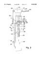
- FIG. 3is an enlarged partial cross-sectional view taken along line 3--3 of FIG. 1.
- FIGS. 1 and 2there is shown in FIGS. 1 and 2 a gantry press generally designated by the numeral 10. Omitted from the drawing for clarity is a drive motor and associated sprockets for propelling the gantry press along the substantially parallel tracks extending along the length of a work surface.
- Such drive mechanismsare well known in the art, for example see such a drive mechanism disclosed in U.S. Pat. No. 3,212,694 issued to Sanford, incorporated herein by reference.
- gantry press 10has a first dolly 12, a second dolly 14 and a roller press 16 mounted and supported between first and second dollies 12 and 14, respectively.
- the gantry pressis drivable along tracks 82 extending in a substantially parallel fashion along the length of work table 78.
- the dollies 12 and 14have a modified A-frame appearance as best shown in FIG. 1. Shown in FIG. 1 is first dolly 12. Second dolly 14 is as mirror image of first dolly 12, therefore, the detailed description of first dolly 12 equally applies to the description of second dolly 14.
- first dolly 12has an upwardly convergent lower side housing members 18 and 20, respectively.
- the lower extremities of side housing members 18 and 20, respectively,are attached to base brace 22 through flange portions 24 with a plurality of bolts therethrough.
- a drive wheel plate 32 with a drive wheel 34is slidably mounted onto parallel members 28 and 30 through slots 33 defined in plate 32 and thru-bolts 35 extending through parallel members 28 and 30. Nuts are threadingly received on thru-bolts 35 to secure plate 32 to parallel members 28 and 30.
- Drive wheel adjustment screws 36are threaded through receiving blocks 37 and attached to drive wheel plate 32 through blocks 38. Blocks 38 are attached to drive wheel plate 32 through welding or other attachment methods.
- a roller press plate 40is slidably mounted onto parallel members 28 and 30 through slots 42 defined in roller press plate 40 and thru-bolts 44 extending from parallel members 28 and 30. Nuts or other securing devices are threadingly received on threaded thru-bolts 44 to slidably secure press plate 40 to parallel members 28 and 30.
- Bearing block 46is attached to roller press plate 40 with bolts 48 and apertures 50 extending therethrough.
- upper brace 62 and cap member 64extends between the upper extremities of parallel members 28 and 30. Upper brace 62 and cap member 64 can be secured to parallel members 28 and 30 with bolts 65 received in threaded apertures or other securing methods.
- two vertical adjustment assembliesare implemented in first dolly 12.
- Vertical adjustment assemblies 300 and 400are implemented in second dolly 14.
- Each assemblyis alike with the equivalent parts. For clarity and simplicity identical parts where shown begin with the numerical prefix of the assembly.
- Vertical adjustment assemblies 100, 200, 300 and 400allows a generally simultaneous four-point adjustment of each side of roller press 16 and along the length of roller press 16 with minimum effort and setup time.
- FIG. 3shown is a cross-sectional detail of vertical adjustment assembly 100. Shown is shaft 102 having a first portion 103 extending through an aperture 104 defined by an inner surface 105 of substantially concentric collar member 106. Collar member 106 extends through collar aperture 108 defined in cap member 64. Collar member 106 is of a sufficient length to match the upper surface face 110 and the bottom surface face 112 of cap member 64 such that collar 106 nests within collar aperture 108.
- a second portion 116 of shaft 102has a larger circumference than first portion 103, forming shoulder 117 between first portion 103 and second portion 116. Thrust bearing 118 is supported by shoulder 117 through drive sprocket 138 and the first portion 103 of shaft 102 extends through thrust bearing 118 and drive sprocket 138. Groove 120 in first portion 103 accepts snap ring 122 to secure assembly 100 in position through aperture 108 defined in upper brace 62 and cap member 64. Second portion 116 of rod 102 has external threads 124 which are received in threaded member 126. Threaded member 126 is integrally formed with block 128 which is secured to roller press plate 40 with bolts, welding, or other securing devices.
- portion 116 and member 126When shaft 102 is rotated, the external threads on portion 116 and the internal threads of member 126 are in threaded engagement and readily feed shaft 102 through threaded member 126 thereby raising or lowering roller press 16 with respect to the frame of dollies 12 and 14, respectively.
- the threaded surfaces on portion 116 and member 126each have a screw ratio sufficient to minimize the torsional force exerted on shaft 102 and to minimize the amount of rotational force that must be exerted on input shaft 135 of right angle gearbox drive 134, thereby readily adjusting the vertical height of massive roller press 16. After the height is set, plates 40 are locked in place by nuts 45 tightened against plates 40 on thru-bolts 44.
- Shaft 102is connected through coupler 130 to gearbox drive shaft 132 extending from right angle gearbox drive 134.
- Drive 134can either be manually operable with hand crank 136 or with a motor (not shown) attached to input shaft 135 of gearbox drive 134.
- a drive sprocket 138is keyed with second portion 116 of shaft 102 such that drive sprocket 138 rotates with shaft 102.
- drive sprocket 138is interconnected with second sprocket 238 through sprocket drive chain 142.
- Sprockets 138 and 238have substantially similar dimensions so that the torsional force applied to shaft 102 is also imparted to second shaft 202 of second vertical adjustment assembly 200 through chain 142, causing the uniform rate of displacement of roller press plate 40 on each side of parallel members 28 and 30, respectively.
- a first end of rod linkage 144is connected through coupler 130 to second output shaft 137 of right angle gearbox drive 134.
- a second end of rod linkage 144is connected through another coupler 130 to first drive shaft 146 of second right angle gearbox drive 148.
- Second drive shaft 150is connected through coupler 130 to a vertical shaft (not shown) of the third vertical adjustment assembly (not shown).
- Rod 144is inserted through a plurality of rod bearings 72 which act to support the rod.
- the rod bearingsare connected through bearing support 74 to transverse bracing member 76.
- Bracing member 76interconnects and braces first dolly 12 with second dolly 14 of gantry press 10.
- parallel gantry press 10is initially configured such that roller press 16 is substantially parallel with the plane defined by work surface 77 of table 78.
- the initial parallel configurationis a calibration procedure in which the roller press 16 is lowered to the work surface sufficient to determine the parallel posture of roller press 16 with work surface 77. If a plane formed by the bottom circumferential arc of the roller press is not aligned with the planar reference provided by work surface 77, rod linkage 144 is disconnected from first right angle gearbox drive 134 and second right angle gearbox drive 148 of both dollies 12 and 14 that each stub shaft 52 and 54, respectively, can be vertically adjusted.
- Plates 40are manually adjusted by actuating first and second right angle gearbox drives, respectively, until roller press 16 comes into a parallel orientation with work surface 77. After alignment is obtained, rod linkage 144 is reconnected to first and second gearbox drives 134 and 148, respectively, so that the vertical position of roller press 16 can be readily adjusted by raising or lowering plates 40 as discussed earlier.
- Gantry press 10can be employed by drivingly engaging drive wheel 34 against top surface of track 82 using a drive motor and sprocket configuration such as is shown in U.S. Pat. No. 3,212,694, for example.
- Dollies 12 and 14, respectively,are movably mounted on track 82 through a plurality of bogie wheels 80.
- Track 18extends the length of a work station or table 78.
- Bogie wheels 80are rotatably connected to base brace 22 drivingly engage track 82 having dual rail surfaces.
- Track 82is attached to table 78 through connecting member 79.
- Other various shades and phases of connectionmay be used to arrange gantry press 10 and table 78 within the same frame of reference.
- both table 78 and track 82can be physically attached to a floor surface.
- each track 82provides a vertically restrictive barrier through the engagement of bogie wheels 80 with flared portion 84 of track 82 as gantry press 10 applies a downward pressure to a truss assembled across work surface 77.
- the truss as shownis a top connector plate T, a series of truss chord and web members M, and a bottom connector plate B. These portions of the truss assembly are placed within a selected template depicted on work surface 77.
- An example of setting-up a truss assemblyis shown in greater detail in U.S. Pat. No. 3,212,594.
- Gantry press 10is driven along track 82 through drive wheel 34 of each dolly 12 and 14, respectively.
- a downward pressureis applied against the truss assembly.
- thrust bearing 118 of first vertical adjustment assembly 100see FIG. 1
- thrust bearings 218, 318 and 418 of the second, third and fourth vertical adjustment assembliesrespectively
- an upward pressureis applied against a bottom surface of upper brace 62 of first and second dollies 12 and 14, accordingly.
- a constant forceis effected in a downward manner against the truss positioned on the work surface while maintaining a vertical adjustment configuration which can readily allow parallel vertical adjustment of roller press 16 with respect to work surface 77 when desired.
- the truss componentscomprising top and bottom connector plates T and B, respectively, and truss members M, are driven together with force sufficient to maintain the truss assembly in an assembled form.
- the truss assemblyis then removed from work surface 77.
- the assemblyis passed through a fixed press such as a stationary roller press (not shown) to firmly connect the truss assembly into a unit.
- right angle gearbox drive 134is activated by turning crank 136.
- shaft 102rotates according to the direction of the crank, causing threads 124 of shaft 102 to engage the threaded member 126 to move along the length of second portion 116 of shaft 102.
- the movement of threaded portion 116causes plate 40 to travel in a vertical direction, thereby vertically moving press roller 16 through the connection of stub shaft 52 with plate 40.
- plates 40 of dollies 12 and 14 and journaled stub shafts 52 and 54, respectively, of the roller press 16are raised or lowered in each dolly 12 and 14, accordingly.
- shaft 202 of second vertical adjustment assembly 200is rotated via sprocket drive chain 142 engaging sprocket 238 mounted on shaft 202.
- the same apparatusis employed in second dolly 14 with respect to the third and the fourth vertical adjustment assemblies.
- Rod 144connected to second right angle gearbox drive 148, conveys the mechanical energy from gearbox drive 134 and crank 136 to second gearbox drive 148.
- the second gearbox drivesimilarly adjusts plate 40 of second dolly 14 concurrently with adjustment of plate 40 of first dolly 12.
- roller press 16is vertically adjusted in a substantially parallel fashion, with the need of tediously adjusting individual bolts and nuts as shown in prior devices.
Landscapes
- Engineering & Computer Science (AREA)
- Mechanical Engineering (AREA)
- Life Sciences & Earth Sciences (AREA)
- Forests & Forestry (AREA)
- Press Drives And Press Lines (AREA)
- Casting Or Compression Moulding Of Plastics Or The Like (AREA)
- Presses And Accessory Devices Thereof (AREA)
Abstract
Description
Claims (5)
Priority Applications (1)
| Application Number | Priority Date | Filing Date | Title |
|---|---|---|---|
| US09/051,322US5933958A (en) | 1995-11-02 | 1996-10-18 | Gantry press height adjustment method |
Applications Claiming Priority (3)
| Application Number | Priority Date | Filing Date | Title |
|---|---|---|---|
| US08/552,194US5768769A (en) | 1995-11-02 | 1995-11-02 | Parallel adjustable gantry truss plate press |
| PCT/US1996/016744WO1997016280A1 (en) | 1995-11-02 | 1996-10-18 | Gantry press with press roll height adjustment |
| US09/051,322US5933958A (en) | 1995-11-02 | 1996-10-18 | Gantry press height adjustment method |
Related Parent Applications (1)
| Application Number | Title | Priority Date | Filing Date |
|---|---|---|---|
| US08/552,194ContinuationUS5768769A (en) | 1995-11-02 | 1995-11-02 | Parallel adjustable gantry truss plate press |
Publications (1)
| Publication Number | Publication Date |
|---|---|
| US5933958Atrue US5933958A (en) | 1999-08-10 |
Family
ID=24204320
Family Applications (2)
| Application Number | Title | Priority Date | Filing Date |
|---|---|---|---|
| US08/552,194Expired - Fee RelatedUS5768769A (en) | 1995-11-02 | 1995-11-02 | Parallel adjustable gantry truss plate press |
| US09/051,322Expired - Fee RelatedUS5933958A (en) | 1995-11-02 | 1996-10-18 | Gantry press height adjustment method |
Family Applications Before (1)
| Application Number | Title | Priority Date | Filing Date |
|---|---|---|---|
| US08/552,194Expired - Fee RelatedUS5768769A (en) | 1995-11-02 | 1995-11-02 | Parallel adjustable gantry truss plate press |
Country Status (5)
| Country | Link |
|---|---|
| US (2) | US5768769A (en) |
| EP (1) | EP0865341A4 (en) |
| AU (1) | AU703478B2 (en) |
| CA (1) | CA2236709C (en) |
| WO (1) | WO1997016280A1 (en) |
Cited By (1)
| Publication number | Priority date | Publication date | Assignee | Title |
|---|---|---|---|---|
| US20040006868A1 (en)* | 2002-07-15 | 2004-01-15 | Ghislain Simard | Truss assembly apparatus with endless track system |
Families Citing this family (8)
| Publication number | Priority date | Publication date | Assignee | Title |
|---|---|---|---|---|
| US5933957A (en) | 1997-10-15 | 1999-08-10 | Mitek Holdings, Inc. | Truss assembly apparatus with independent roller drive |
| US6317980B2 (en) | 1997-10-20 | 2001-11-20 | Mitek Holdings, Inc. | Laser jigging system for assembly of trusses and method of use |
| US6817090B1 (en) | 1998-10-13 | 2004-11-16 | Mcadoo David L. | Truss fabrication method and apparatus |
| US6560858B1 (en) | 2000-10-20 | 2003-05-13 | Alpine Engineered Products, Inc. | Truss table apparatus with automatic truss movement assembly and method |
| US6807903B2 (en)* | 2002-08-30 | 2004-10-26 | Mitek Holdings, Inc. | Truss assembly apparatus |
| US6976305B2 (en)* | 2003-10-07 | 2005-12-20 | Mitek Holdings, Inc. | Adjustable table leg for truss fabrication system |
| US8393266B2 (en)* | 2009-07-20 | 2013-03-12 | Lifestyle Crafts, Llc | Systems and methods applying a design on a medium |
| CN107350773A (en)* | 2017-08-29 | 2017-11-17 | 宁波必沃纺织机械有限公司 | A kind of inserted sheet rolling riveter |
Citations (21)
| Publication number | Priority date | Publication date | Assignee | Title |
|---|---|---|---|---|
| US2811186A (en)* | 1955-02-09 | 1957-10-29 | Raymond L Honza | Adjustable nailing forms |
| US3036609A (en)* | 1959-05-25 | 1962-05-29 | Jr Milford S Quesenberry | Jig |
| US3195449A (en)* | 1963-05-15 | 1965-07-20 | Automated Building Components | Concrete press |
| US3212694A (en)* | 1962-11-26 | 1965-10-19 | Sanford Ind Inc | Apparatus for fabricating wooden structures |
| US3255943A (en)* | 1964-04-02 | 1966-06-14 | Sanford Ind Inc | Apparatus for fabricating wooden structures |
| US3336865A (en)* | 1965-01-21 | 1967-08-22 | Brand Charles | Etching press |
| US3413703A (en)* | 1966-07-26 | 1968-12-03 | Sanford Arthur C | Method for fabricating trusses in horizontal position |
| US3538843A (en)* | 1968-10-15 | 1970-11-10 | Rose Lubin | Truss forming apparatus |
| US3667379A (en)* | 1971-01-11 | 1972-06-06 | Templin Associates Inc | Apparatus for prefabricating wood structures |
| US3855917A (en)* | 1973-10-15 | 1974-12-24 | Dayton Aircraft Prod Inc | Truss plate press |
| US3925870A (en)* | 1974-01-21 | 1975-12-16 | James D Adams | Truss assembly jig |
| US4295269A (en)* | 1979-05-31 | 1981-10-20 | Wright Ronald F | Truss assembly apparatus |
| US4437234A (en)* | 1982-01-15 | 1984-03-20 | Thornton Jack L | Truss assembling gantry |
| US4660815A (en)* | 1984-01-11 | 1987-04-28 | Production Equipment & Engineering Co. | Pressure actuated clamp for truss manufacturing equipment |
| US4943038A (en)* | 1989-07-17 | 1990-07-24 | Alpine Engineered Products, Inc. | Truss assembly apparatus |
| US5085414A (en)* | 1990-04-27 | 1992-02-04 | Weaver Austin S | Jig for forming trusses and the like |
| US5092028A (en)* | 1989-06-29 | 1992-03-03 | Alpine Engineered Products, Inc. | Apparatus for assembly of wood structures |
| US5111861A (en)* | 1988-09-13 | 1992-05-12 | Truswal Systems Corporation | Apparatus for cambering wood trusses |
| US5211108A (en)* | 1990-11-02 | 1993-05-18 | Truswal Systems Corporation | Truss assembly apparatus with vertically adjustable press roller |
| US5285720A (en)* | 1992-10-02 | 1994-02-15 | Wright Ronnie F | Apparatus and method of manufacturing wood trusses |
| US5553375A (en)* | 1994-09-21 | 1996-09-10 | Tee-Lok Corporation | Apparatus for manufacturing trusses and associated method |
- 1995
- 1995-11-02USUS08/552,194patent/US5768769A/ennot_activeExpired - Fee Related
- 1996
- 1996-10-18WOPCT/US1996/016744patent/WO1997016280A1/ennot_activeApplication Discontinuation
- 1996-10-18AUAU74562/96Apatent/AU703478B2/ennot_activeCeased
- 1996-10-18CACA002236709Apatent/CA2236709C/ennot_activeExpired - Fee Related
- 1996-10-18USUS09/051,322patent/US5933958A/ennot_activeExpired - Fee Related
- 1996-10-18EPEP96936707Apatent/EP0865341A4/ennot_activeWithdrawn
Patent Citations (21)
| Publication number | Priority date | Publication date | Assignee | Title |
|---|---|---|---|---|
| US2811186A (en)* | 1955-02-09 | 1957-10-29 | Raymond L Honza | Adjustable nailing forms |
| US3036609A (en)* | 1959-05-25 | 1962-05-29 | Jr Milford S Quesenberry | Jig |
| US3212694A (en)* | 1962-11-26 | 1965-10-19 | Sanford Ind Inc | Apparatus for fabricating wooden structures |
| US3195449A (en)* | 1963-05-15 | 1965-07-20 | Automated Building Components | Concrete press |
| US3255943A (en)* | 1964-04-02 | 1966-06-14 | Sanford Ind Inc | Apparatus for fabricating wooden structures |
| US3336865A (en)* | 1965-01-21 | 1967-08-22 | Brand Charles | Etching press |
| US3413703A (en)* | 1966-07-26 | 1968-12-03 | Sanford Arthur C | Method for fabricating trusses in horizontal position |
| US3538843A (en)* | 1968-10-15 | 1970-11-10 | Rose Lubin | Truss forming apparatus |
| US3667379A (en)* | 1971-01-11 | 1972-06-06 | Templin Associates Inc | Apparatus for prefabricating wood structures |
| US3855917A (en)* | 1973-10-15 | 1974-12-24 | Dayton Aircraft Prod Inc | Truss plate press |
| US3925870A (en)* | 1974-01-21 | 1975-12-16 | James D Adams | Truss assembly jig |
| US4295269A (en)* | 1979-05-31 | 1981-10-20 | Wright Ronald F | Truss assembly apparatus |
| US4437234A (en)* | 1982-01-15 | 1984-03-20 | Thornton Jack L | Truss assembling gantry |
| US4660815A (en)* | 1984-01-11 | 1987-04-28 | Production Equipment & Engineering Co. | Pressure actuated clamp for truss manufacturing equipment |
| US5111861A (en)* | 1988-09-13 | 1992-05-12 | Truswal Systems Corporation | Apparatus for cambering wood trusses |
| US5092028A (en)* | 1989-06-29 | 1992-03-03 | Alpine Engineered Products, Inc. | Apparatus for assembly of wood structures |
| US4943038A (en)* | 1989-07-17 | 1990-07-24 | Alpine Engineered Products, Inc. | Truss assembly apparatus |
| US5085414A (en)* | 1990-04-27 | 1992-02-04 | Weaver Austin S | Jig for forming trusses and the like |
| US5211108A (en)* | 1990-11-02 | 1993-05-18 | Truswal Systems Corporation | Truss assembly apparatus with vertically adjustable press roller |
| US5285720A (en)* | 1992-10-02 | 1994-02-15 | Wright Ronnie F | Apparatus and method of manufacturing wood trusses |
| US5553375A (en)* | 1994-09-21 | 1996-09-10 | Tee-Lok Corporation | Apparatus for manufacturing trusses and associated method |
Non-Patent Citations (20)
| Title |
|---|
| Product Brochure Fabrication & Cutting Equipment for Truss Manufacturing , MiTek Industries Group of Companies, 1988.* |
| Product Brochure Floor Roller, Ultra High Speed Floor Truss Machine , MiTek Industries, Inc., 1988.* |
| Product Brochure Gantry Roller, C.M.F., Inc., date unknown.* |
| Product Brochure Gantry, For Large Trusses and Long Production Runs , MiTek Industries, Inc., 1991.* |
| Product Brochure Mark 8 Press, Truss Fabrication Equipment , MiTek Industries, Inc., 1988.* |
| Product Brochure Mark V, Fully Automatic Moving Press System , MiTek Industries, Inc., 1988.* |
| Product Brochure Other Features of the Trussmaker , Tee Lock Corporation, date unknown.* |
| Product Brochure Roller Gantry, Roller Press System , MiTek Industries, Inc., date unknown.* |
| Product Brochure Roof Truss Gantry System , Klaisler Mfg. Corp., date unknown.* |
| Product Brochure Super Torque Gantry System , source unknown.* |
| Product Brochure--Fabrication & Cutting Equipment for Truss Manufacturing, MiTek Industries Group of Companies, 1988. |
| Product Brochure--Floor Roller, Ultra High-Speed Floor Truss Machine, MiTek Industries, Inc., 1988. |
| Product Brochure--Gantry Roller, C.M.F., Inc., date unknown. |
| Product Brochure--Gantry, For Large Trusses and Long Production Runs, MiTek Industries, Inc., 1991. |
| Product Brochure--Mark V, Fully Automatic Moving Press System, MiTek Industries, Inc., 1988. |
| Product Brochure--Mark-8-Press, Truss Fabrication Equipment, MiTek Industries, Inc., 1988. |
| Product Brochure--Other Features of the Trussmaker, Tee Lock Corporation, date unknown. |
| Product Brochure--Roller Gantry, Roller Press System, MiTek Industries, Inc., date unknown. |
| Product Brochure--Roof Truss Gantry System, Klaisler Mfg. Corp., date unknown. |
| Product Brochure--Super Torque Gantry System, source unknown. |
Cited By (2)
| Publication number | Priority date | Publication date | Assignee | Title |
|---|---|---|---|---|
| US20040006868A1 (en)* | 2002-07-15 | 2004-01-15 | Ghislain Simard | Truss assembly apparatus with endless track system |
| US7065865B2 (en) | 2002-07-15 | 2006-06-27 | Ghislain Simard | Truss assembly apparatus with endless track system |
Also Published As
| Publication number | Publication date |
|---|---|
| EP0865341A4 (en) | 2000-10-04 |
| WO1997016280A1 (en) | 1997-05-09 |
| US5768769A (en) | 1998-06-23 |
| AU703478B2 (en) | 1999-03-25 |
| CA2236709A1 (en) | 1997-05-09 |
| AU7456296A (en) | 1997-05-22 |
| CA2236709C (en) | 2004-09-21 |
| EP0865341A1 (en) | 1998-09-23 |
Similar Documents
| Publication | Publication Date | Title |
|---|---|---|
| US5933958A (en) | Gantry press height adjustment method | |
| CN112067450A (en) | Building quality detection system flexible to adjust | |
| CA1191773A (en) | Device for joining plies for tires | |
| CN106739381A (en) | A kind of brown paper diaphragm gluing pressing device of strong applicability | |
| FI77399B (en) | FANERSVARV OCH FOERFARANDE FOER SVARVNING AV FANER. | |
| US5676358A (en) | Variable height jig stop assembly and alignment plates for truss table | |
| EP0541728A1 (en) | Apparatus and method for producing a bent laminate | |
| CN113146127A (en) | Automatic fixed clamping tool for production and processing of low-voltage power distribution cabinet | |
| CN220515799U (en) | Welding machine for motorcycle frame production | |
| CN219452007U (en) | Drilling equipment is used in public engineering construction of municipal administration | |
| US4031941A (en) | Concentric contra-rotating bead deflector mechanism for tire mounting apparatus | |
| CN212634848U (en) | Welding device for producing standard section of tower crane | |
| CN210286646U (en) | Piano hoisting apparatus | |
| CA2173163C (en) | Pallet disassembler | |
| CN109884497A (en) | A kind of basketball court display screen circuit board inspection platform convenient for adjusting | |
| CN2495393Y (en) | Machine for aligning steel bar | |
| CN215207651U (en) | Adjustable conveying device for mask equipment | |
| CN221050819U (en) | Stop gear for material conveying | |
| CN216578361U (en) | Energy-conserving high frequency plank makeup machine | |
| CN215374335U (en) | A bolt torque calibration device | |
| CN219859324U (en) | Rotary jacking device | |
| CN220127252U (en) | Shaping device of shaping machine | |
| CN217528778U (en) | Shape correcting device for elevator shock absorber framework | |
| CN220838733U (en) | Annular welding auxiliary tool | |
| CN222847841U (en) | Adjustable pipe truss spliced supporting jig frame |
Legal Events
| Date | Code | Title | Description |
|---|---|---|---|
| AS | Assignment | Owner name:ALPINE ENGINEERED PRODUCTS, INC., FLORIDA Free format text:ASSIGNMENT OF ASSIGNORS INTEREST;ASSIGNOR:SHAMBLIN, WAYNE A.;REEL/FRAME:009266/0546 Effective date:19951102 | |
| CC | Certificate of correction | ||
| FEPP | Fee payment procedure | Free format text:PAT HOLDER CLAIMS SMALL ENTITY STATUS, ENTITY STATUS SET TO SMALL (ORIGINAL EVENT CODE: LTOS); ENTITY STATUS OF PATENT OWNER: LARGE ENTITY | |
| REFU | Refund | Free format text:REFUND - PAYMENT OF MAINTENANCE FEE, 4TH YEAR, LARGE ENTITY (ORIGINAL EVENT CODE: R1551); ENTITY STATUS OF PATENT OWNER: LARGE ENTITY | |
| FPAY | Fee payment | Year of fee payment:4 | |
| FEPP | Fee payment procedure | Free format text:PAT HOLDER NO LONGER CLAIMS SMALL ENTITY STATUS, ENTITY STATUS SET TO UNDISCOUNTED (ORIGINAL EVENT CODE: STOL); ENTITY STATUS OF PATENT OWNER: LARGE ENTITY | |
| AS | Assignment | Owner name:ANTARES CAPITAL CORPORATION, AS AGENT, ILLINOIS Free format text:SECURITY AGREEMENT;ASSIGNOR:ALPINE ENGINEERED PRODUCTS, INC.;REEL/FRAME:016274/0297 Effective date:20050714 | |
| FPAY | Fee payment | Year of fee payment:8 | |
| AS | Assignment | Owner name:ILLINOIS TOOL WORKS INC., ILLINOIS Free format text:ASSIGNMENT OF ASSIGNORS INTEREST;ASSIGNOR:ALPINE ENGINEERED PRODUCTS, INC.;REEL/FRAME:018904/0431 Effective date:20061121 | |
| REMI | Maintenance fee reminder mailed | ||
| LAPS | Lapse for failure to pay maintenance fees | ||
| STCH | Information on status: patent discontinuation | Free format text:PATENT EXPIRED DUE TO NONPAYMENT OF MAINTENANCE FEES UNDER 37 CFR 1.362 | |
| FP | Lapsed due to failure to pay maintenance fee | Effective date:20110810 |