US5933132A - Method and apparatus for calibrating geometrically an optical computer input system - Google Patents
Method and apparatus for calibrating geometrically an optical computer input systemDownload PDFInfo
- Publication number
- US5933132A US5933132AUS08/648,659US64865996AUS5933132AUS 5933132 AUS5933132 AUS 5933132AUS 64865996 AUS64865996 AUS 64865996AUS 5933132 AUS5933132 AUS 5933132A
- Authority
- US
- United States
- Prior art keywords
- distortion
- coordinate values
- image
- coordinate
- determined
- Prior art date
- Legal status (The legal status is an assumption and is not a legal conclusion. Google has not performed a legal analysis and makes no representation as to the accuracy of the status listed.)
- Expired - Fee Related
Links
Images


Classifications
- G—PHYSICS
- G06—COMPUTING OR CALCULATING; COUNTING
- G06F—ELECTRIC DIGITAL DATA PROCESSING
- G06F3/00—Input arrangements for transferring data to be processed into a form capable of being handled by the computer; Output arrangements for transferring data from processing unit to output unit, e.g. interface arrangements
- G06F3/01—Input arrangements or combined input and output arrangements for interaction between user and computer
- G06F3/03—Arrangements for converting the position or the displacement of a member into a coded form
- G06F3/041—Digitisers, e.g. for touch screens or touch pads, characterised by the transducing means
- G06F3/042—Digitisers, e.g. for touch screens or touch pads, characterised by the transducing means by opto-electronic means
- G06F3/0425—Digitisers, e.g. for touch screens or touch pads, characterised by the transducing means by opto-electronic means using a single imaging device like a video camera for tracking the absolute position of a single or a plurality of objects with respect to an imaged reference surface, e.g. video camera imaging a display or a projection screen, a table or a wall surface, on which a computer generated image is displayed or projected
- H—ELECTRICITY
- H04—ELECTRIC COMMUNICATION TECHNIQUE
- H04N—PICTORIAL COMMUNICATION, e.g. TELEVISION
- H04N9/00—Details of colour television systems
- H04N9/12—Picture reproducers
- H04N9/31—Projection devices for colour picture display, e.g. using electronic spatial light modulators [ESLM]
- H04N9/3179—Video signal processing therefor
- H04N9/3185—Geometric adjustment, e.g. keystone or convergence
Definitions
- the present inventionrelates in general to a method in apparatus for calculating geometrically an optical computer input system. It more particularly relates to a system for calibrating geometrically for distortion in connection with such an optical computer input system is shown and described in the said patent application.
- a new optical computer input systemis shown and described in said parent patent application.
- Such systemenable the use to shine a high intensity light onto a screen bearing a computer generated image to provide auxiliary information for the computer.
- Such an input systemincludes an optical sensing device, such as a charged coupled device camera focused on to the screen.
- the systemcan detect high intensity light images and discriminate them from the computer generated images, to input information interactively into the computer, in a convenient manner, even in very low ambient light conditions.
- the screen onto which is projected the computer generated imagemay not be a perfect rectangle as presented to the sensing device or camera.
- the screenmay be tilted either forward or backward, or from side to side, or any combination thereof.
- the sensing device or camerawill not track properly relative to the image visualized from the screen.
- a third problemis caused by the improper alignment of a projection panel on the stage of the overhead projector.
- the panelis not accurately aligned in a parallel manner on all sides relative to the projector's stage, the resulting image projected onto the screen will also be askew.
- a fourth problemrelates to the project itself not being properly aligned relative to the screen. Such is commonly the case where the neck portion of the overhead projector may be bent slightly due to excessive use or wear. This causes a result similar to the improper registration of the panel on the stage of the projector.
- a still further problem of geometric alignmentis caused by the camera or sensing device being tilted at an angle being tilted upwardly, or downwardly, relative to the plane of the screen. The result is that a distortion may occur.
- the camerais unable to accurately plot the various coordinates visualized from the image projected on to the screen.
- trackingis not able to be perfectly accomplished.
- the cameramay not accurately know the precise coordinates of the spot of light projected onto the screen.
- the computermay not accurately respond to the position of the light and incorrect data can be entered. Thus, erroneous results might occur.
- the principle object of the present inventionis to provide a new and improved geometric correction arrangement for an optical imaging system.
- a geometric systemwhich includes an arrangement for generating geometrically compensated relative coordinates for a projected image and for storing such coordinates.
- the system of the present inventionproduces a normalization of the image of the screen to provide for the necessary correction.
- the resulting coordinates stored by the systemare continuously used to adjust or convert the coordinates sensed by the camera.
- suitable corrections for the distortedare produced.
- FIG. 1is a block diagram of the imaging system
- FIGS. 2 through 11are diagrammatic views of various images or portions of images helpful in understanding the operation of the present invention.
- FIGS. 12 through 17are flow charts of computer software for the system of FIG. 1 to illustrate the operation of the geometric correction arrangement.
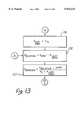
- the computer input system 10which modifies computer generated images appearing on a screen 21, and which is constructed in accordance with the present invention.
- the computer input system 10generally includes an image projection/detection system or arrangement 11 whose input path (cable 17A) is coupled to the output of a video port 17 of a computer 16.
- the arrangement 11comprises a liquid crystal panel 13 and a charge coupled device image sensor 14.
- the computer 16is a conventional personal computer, such as a model PS/2 personal computer manufactured by International Business Machines.
- the computer 16includes a video monitor 19A and keyboard 19B.
- the panel 13is driven by the computer 16 for generating live images which are projected by an overhead head projector 22 onto the screen 21.
- the computer input system 10also includes a signal processing unit 25 coupled between the output path (cable 14A) of the image/detection arrangement 11 and the input serial port 18 of the computer 16 via cable 25A.
- the computer input system 10further includes a light wand or light generating pointing device 24, or a laser light generating device.
- the projection/detection arrangement 11detects the presence of auxiliary light image or spot projected onto the viewing surface 21 by the handheld/battery-operated light generating device 24, and generates an analog electrical signal which is coupled to the signal processing unit 25 via cable 14A.
- the signal processing unit 25responds to the analog signal, and converts the signal into digital pixel coordinates reference signals which identify the relative position of the auxiliary light image on screen 21, which are transferred into the computer 16 via the output cable 25A.
- Cable 25Ais connected to the serial input port 18 of the computer 16.
- Computer 16responds to the pixel coordinates signals and can alter its application program which causes the computer generated image being projected onto the screen 21 to be modified. For example, the computer generated projected image on the viewing area 21 can be modified in accordance with the information contained in the coordinate references signals.
- the firmware stored in the signal processor 25provides the necessary geometric correction for the image in accordance with the present invention.
- the correctioncommences by projecting a bright rectangular light onto the screen to determine what correction is necessary and then record the necessary information for converting the coordinates to an adjusted relative coordinate.
- a true rectangular imageis indicated at 80.
- each one of the four sides of the imagecan be distorted in a generally rectangular manner.
- On each side of the rectangular image 80there are two possible triangular area of distortion possible.
- the arrangement of the present inventiondetermines which one of the two triangular areas of distortion are present for each side of the rectangular image. Once that determination is made, a formula for the relative correction is generated and stored in the signal processor.
- FIG. 3there is shown an example of a grossly distorted rectangular image 90 as an example.
- the first portion of the process or technique for doing the correctionis the actual corners of the projected image are shown.
- the coordinates for the individual cornersare shown in FIG. 3.
- the technique for determining the cornersare similar as shown and described in the parent applications.
- a defined central coordinate of X , Yis located at the intersection of the diagonals of the corners as indicated in FIG. 3.
- four quadrants of the generally rectangular imageare important to know for the purposes of the invention.
- the relative coordinates for the identified spot of light on the screencan be determined accordingly.
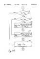
- the software in the signal processor 25determines the coordinates of the four corners of the image appearing on the screen, as indicated at box 121 of FIG. 12.
- the image sensor 14determines the interface between the bright image and the remaining portion of the screen, in a similar manner as described in the parent patent applications.
- the geometric center of the screenis determined and defined at the intersection of diagonal lines extending through the corners. And thereafter, as indicated in box 123, particular coordinates of a spot of light projected onto the screen by the handheld light device 24 is determined. In this regard, a position X of the spot of light is determined to be either left of center or not. If it is determined to be left of center, then the software will analyze whether the left edge is in perfect vertical alignment or whether it is distorted according to either one or the other triangular areas of distortion 81 or 82, as indicated more clearly in FIGS. 4 and 5. As indicated in box 124, a determination is made as to whether or not the left edge is a perfectly aligned vertical edge.
- the X coordinate of the top, left corneris compared with the X coordinate bottom, left corner. If they are equal, then the edge is determined to be perfectly oriented in a vertical disposition, and thus correction is not required. If such occurs, box 131 of FIG. 13 is entered.
- the decision box 125is entered as shown in FIG. 12 to determine whether the X coordinate of the top left corner is greater than the bottom left corner. This determination is made to learn whether there is rectangular distortion area 81 (FIG. 4), or a triangular area of distortion shown at 82 of FIG. 5.
- the triangular area 81is in the shape of a right triangle having its based aligned with the bottom edge of the rectangular image.
- the rectangular area 82is inverted from the area 81, and has its base coextensive with the top edge of the rectangular image area.
- the box 126is entered and the left edge X coordinate is calculated in the box 126. Thereafter, at the boxes 132, 133 the absolute value of the X coordinate of the spot is calculated. This value of the X coordinate is then used for sending to the computer 16, instead of sending of the value of the X coordinate of the spot of light as detected by the sensor 14.
- the formula shown in the boxes 132 and 133are used to scale the X coordinate of the spot of light on the screen 21 to correct geometrically for any distortions. It should be understood that this X coordinate correction is calculated on the slide for each spot of light detected by the image sensor 14.
- the initial storing of the X and Y coordinates of the four corners and the defined centeris the only information that need be saved during initialization process. Thereafter, the absolute values of the X and Y coordinates of the spot of light are calculated and supplied to the host computer 16 on the fly.
- the decision box 125 of FIG. 12will determine that the top left X coordinate is not greater than the bottom left X coordinate, so that the box 126 is entered to calculate the left edge X coordinate. After so calculating, the boxes 132 and 133 are entered to determine a different X ABSOLUTE value based upon the triangular area 81 of distortion.
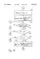
- box 141there is determination made as to whether the top right X coordinate is equal to the bottom right X coordinate. If they are equal then box 145 is entered directly to determine if the right edge X coordinate is equal to the X coordinate of the top right edge.
- the box 142is entered to determine whether or not the top right X coordinate is greater than the bottom right X coordinate. If it is, then the right edge X coordinate is calculated by the formula shown in box 143. Thereafter, as indicated by box 151 and 152, the absolute value of the X coordinate is then calculated knowing the right edge X coordinate and the X coordinate of the light spot and the X coordinate of the defined center. This absolute value of X is then used and supplied to the host computer 16.
- the triangular area 83(FIG. 2) is identified and the box 144 is entered to calculate the X coordinate of the right edge, thereafter, calculations are made at boxes 151 and 152 calculating the absolute value of the X coordinate.
- the quadrant of the light spotis first determined at box 153. In this regard, at box 153 a determination is made as to whether or not the Y position of the spot is above the defined center. If it is, then the decision box 154 is entered to determine whether the top edge is either horizontal or whether there are either one or two triangular areas 85 or 86 as shown in FIG. 2.
- a box 176 in FIG. 17is entered to prepare and transmit to the host computer once both absolute value of the X coordinate and the absolute value of the Y coordinates have been calculated. It should be noted that once these absolute values have been transmitted, the routine loops back to the initial box 123 to repeat the cycle of operation for the next light spot detected.
- the decision box 165 of FIG. 16is entered. A determination is then as to whether or not the bottom left Y coordinate is equal to the bottom right Y coordinate. The purpose of this determination is to decide whether the bottom edge of the rectangular viewing area is either horizontal, or at a triangular position as indicated at either 87 or 88 in FIG. 2. If it is determined that the bottom edge is a true horizontal line, then the boxes 173 through 175 are entered to calculate the value of the absolute value of Y as previously explained. On the other hand, if they are not equal, then the decision made in box 165 determines whether or not the bottom left Y coordinate is greater than the bottom right Y coordinate.
- the box 171is entered to perform a calculation to determine the bottom edge value of the Y coordinate. This calculation is based on the triangular area 88, since the bottom left Y coordinate is greater than the bottom right Y coordinate. If the reverse is true, then the calculation is made at box 172 based on the triangular area 87 to determine the bottom edge Y coordinate. Thereafter, the absolute value of the Y coordinate is calculated as previously described.
Landscapes
- Engineering & Computer Science (AREA)
- General Engineering & Computer Science (AREA)
- Multimedia (AREA)
- Physics & Mathematics (AREA)
- Theoretical Computer Science (AREA)
- Human Computer Interaction (AREA)
- General Physics & Mathematics (AREA)
- Geometry (AREA)
- Signal Processing (AREA)
- Image Processing (AREA)
Abstract
Description
y-Y.sub.BR =m.sub.LR (x-X.sub.BR) (3)
y-Y.sub.BL =m.sub.RL (x-X.sub.BL) (4)
y-Y.sub.BR =m.sub.LR x-m.sub.LR x.sub.BL (5)
y-Y.sub.BL =m.sub.RL x-m.sub.RL X.sub.BL (6)
y-m.sub.LR x=Y.sub.BR -m.sub.LR x.sub.BR (7)
y-m.sub.RL x=Y.sub.BL -m.sub.RL X.sub.BL (8) ##EQU2## SUBSTITUTING INTO FIRST EQUATION
y.sub.c =m.sub.LR X.sub.C -m.sub.LR X.sub.BR +Y.sub.BR (12)
Y.sub.C =m.sub.LR X.sub.C -m.sub.LR X.sub.BR +Y.sub.BR (13)
SIDEOPP(ADJUSTMENT)=(DISTANCE)(TANα), WHERE DISTANCE EQUALS SIDE ADJ.(15)
X.sub.RELATIVE =X.sub.RAW -X.sub.HOME NOTE: IF X.sub.REL IS NEGATIVE THEN POSITION IS OUTSIDE OF SCREEN. (17) ##EQU5## REFERRING TO FIG. 5, FOR A LEFT EDGE OF ##EQU6##
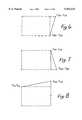
X.sub.REL =X.sub.RAW -X.sub.HOME (NOTE: IF X.sub.REL IS NEGATIVE THEN POSITIVE IS OUTSIDE OF SCREEN (20) ##EQU7## REFERRING TO FIG. 6, FOR THE RIGHT EDGE OF ##EQU8##
X.sub.REL =X.sub.RAW -X.sub.o (NOTE: IF X.sub.RAN >X.sub.RIGHT THEN OUTSIDE OF SCREEN) (23) ##EQU9## REFERRING TO FIG. 7, FOR A RIGHT EDGE OF ##EQU10##
X.sub.REL =X.sub.RAW -X.sub.C (NOTE: IF X.sub.RAW >X.sub.RIGHT THEN OUTSIDE OF SCREEN) (26) ##EQU11## REFERRING TO FIG. 8, FOR A TOP EDGE OF ##EQU12##
Y.sub.REL =Y.sub.RAW -Y.sub.HOME NOTE: IF Y.sub.RAW <Y.sub.HOME THEN OUTSIDE OF SCREEN) (29) ##EQU13## REFERRING TO FIG. 9, FOR A TOP EDGE OF ##EQU14##
Y.sub.REL =Y.sub.RAW -Y.sub.HOME ((NOTE: IF Y.sub.RAW <Y.sub.HOME THEN OUTSIDE OF SCREEN) (32) ##EQU15## REFERRING TO FIG. 10, FOR A BOTTOM EDGE OF ##EQU16##
Y.sub.REL =Y.sub.RAW -Y.sub.C (NOTE: IF Y.sub.RAW >Y.sub.BOTTOM THEN OUTSIDE OF SCREEN) (35) ##EQU17## REFERRING TO FIG. 11, FOR A BOTTOM EDGE OF ##EQU18##
Y.sub.REL =Y.sub.RAW -Y.sub.C (NOTE: IF Y.sub.RAW >Y.sub.BOTTOM THEN OUTSIDE OF SCREEN) (38) ##EQU19##
Claims (18)
Y.sub.relative =Y.sub.SPOT -Y.sub.c.
X.sub.relative =X.sub.SPOT -X.sub.left edge.
Priority Applications (1)
| Application Number | Priority Date | Filing Date | Title |
|---|---|---|---|
| US08/648,659US5933132A (en) | 1989-11-07 | 1996-05-15 | Method and apparatus for calibrating geometrically an optical computer input system |
Applications Claiming Priority (6)
| Application Number | Priority Date | Filing Date | Title |
|---|---|---|---|
| US43302989A | 1989-11-07 | 1989-11-07 | |
| US07/611,416US5181015A (en) | 1989-11-07 | 1990-11-09 | Method and apparatus for calibrating an optical computer input system |
| US65680391A | 1991-02-14 | 1991-02-14 | |
| US11552293A | 1993-08-31 | 1993-08-31 | |
| US34290594A | 1994-11-21 | 1994-11-21 | |
| US08/648,659US5933132A (en) | 1989-11-07 | 1996-05-15 | Method and apparatus for calibrating geometrically an optical computer input system |
Related Parent Applications (2)
| Application Number | Title | Priority Date | Filing Date |
|---|---|---|---|
| US07/611,416Continuation-In-PartUS5181015A (en) | 1989-11-07 | 1990-11-09 | Method and apparatus for calibrating an optical computer input system |
| US34290594AContinuation | 1989-11-07 | 1994-11-21 |
Publications (1)
| Publication Number | Publication Date |
|---|---|
| US5933132Atrue US5933132A (en) | 1999-08-03 |
Family
ID=27537422
Family Applications (1)
| Application Number | Title | Priority Date | Filing Date |
|---|---|---|---|
| US08/648,659Expired - Fee RelatedUS5933132A (en) | 1989-11-07 | 1996-05-15 | Method and apparatus for calibrating geometrically an optical computer input system |
Country Status (1)
| Country | Link |
|---|---|
| US (1) | US5933132A (en) |
Cited By (25)
| Publication number | Priority date | Publication date | Assignee | Title |
|---|---|---|---|---|
| US20010010522A1 (en)* | 2000-01-27 | 2001-08-02 | Mitsubishi Denki Kabushiki Kaisha | Three-dimensional graphic processing device for drawing polygon having vertex data defined by relative value and method therefor |
| US20010024231A1 (en)* | 2000-03-21 | 2001-09-27 | Olympus Optical Co., Ltd. | Stereoscopic image projection device, and correction amount computing device thereof |
| US20020197584A1 (en)* | 2001-06-08 | 2002-12-26 | Tansel Kendir | Firearm laser training system and method facilitating firearm training for extended range targets with feedback of firearm control |
| US20030002751A1 (en)* | 2001-03-02 | 2003-01-02 | Hung-Ming Sun | Method of correcting an image with perspective distortion and producing an artificial image with perspective distortion |
| WO2001071665A3 (en)* | 2000-03-17 | 2003-01-16 | Sun Microsystems Inc | A graphics system having a super-sampled sample buffer with hot spot correction, edge blending, edge matching, distortion correction, and chromatic distortion compensation |
| US6600478B2 (en)* | 2001-01-04 | 2003-07-29 | International Business Machines Corporation | Hand held light actuated point and click device |
| US6616452B2 (en) | 2000-06-09 | 2003-09-09 | Beamhit, Llc | Firearm laser training system and method facilitating firearm training with various targets and visual feedback of simulated projectile impact locations |
| US20030210381A1 (en)* | 2002-05-10 | 2003-11-13 | Nec Viewtechnology, Ltd. | Method of correcting for distortion of projected image, distortion correcting program used in same method, and projection-type image display device |
| US6690354B2 (en)* | 2000-11-19 | 2004-02-10 | Canesta, Inc. | Method for enhancing performance in a system utilizing an array of sensors that sense at least two-dimensions |
| US6704000B2 (en)* | 2000-11-15 | 2004-03-09 | Blue Iris Technologies | Method for remote computer operation via a wireless optical device |
| US6747636B2 (en)* | 1991-10-21 | 2004-06-08 | Smart Technologies, Inc. | Projection display and system with pressure sensing at screen, and computer assisted alignment implemented by applying pressure at displayed calibration marks |
| US6753907B1 (en)* | 1999-12-23 | 2004-06-22 | Justsystem Corporation | Method and apparatus for automatic keystone correction |
| US20050041216A1 (en)* | 2003-07-02 | 2005-02-24 | Seiko Epson Corporation | Image processing system, projector, program, information storage medium, and image processing method |
| US20060101349A1 (en)* | 2000-05-29 | 2006-05-11 | Klony Lieberman | Virtual data entry device and method for input of alphanumeric and other data |
| US20060187199A1 (en)* | 2005-02-24 | 2006-08-24 | Vkb Inc. | System and method for projection |
| US20070188447A1 (en)* | 2006-02-15 | 2007-08-16 | Pixart Imaging, Inc. | Light-pointing device and light-tracking receiver having a function selection key and system using the same |
| US20070206159A1 (en)* | 2002-04-08 | 2007-09-06 | Nec Viewtechnology, Ltd. | Method for correcting for distortion of projected image, program for correcting image distortion, and projection-type image display device |
| US20080018591A1 (en)* | 2006-07-20 | 2008-01-24 | Arkady Pittel | User Interfacing |
| EP1363239A3 (en)* | 2000-03-17 | 2008-07-30 | Sun Microsystems, Inc. | A graphics system having a super-sampled sample buffer with hot spot correction,edge blending, edge matching, distortion correction and chromatic distortion compensation |
| US7427983B1 (en) | 2002-06-02 | 2008-09-23 | Steelcase Development Corporation | Visual communication system |
| CN100422913C (en)* | 2004-06-28 | 2008-10-01 | 微光科技股份有限公司 | Array type photoreceptor index system and method thereof |
| US20110191690A1 (en)* | 2010-02-03 | 2011-08-04 | Microsoft Corporation | Combined Surface User Interface |
| US20150062089A1 (en)* | 2013-05-09 | 2015-03-05 | Stephen Howard | System and method for motion detection and interpretation |
| US10891003B2 (en) | 2013-05-09 | 2021-01-12 | Omni Consumer Products, Llc | System, method, and apparatus for an interactive container |
| US12120471B2 (en) | 2014-12-30 | 2024-10-15 | Omni Consumer Products, Llc | System and method for interactive projection |
Citations (3)
| Publication number | Priority date | Publication date | Assignee | Title |
|---|---|---|---|---|
| US4857998A (en)* | 1987-02-26 | 1989-08-15 | Matsushita Electric Industrial Co., Ltd. | Automatic primary color convergence alignment system for projection television |
| US5070465A (en)* | 1987-02-25 | 1991-12-03 | Sony Corporation | Video image transforming method and apparatus |
| US5091773A (en)* | 1989-10-03 | 1992-02-25 | Thomson-Csf | Process and device for image display with automatic defect correction by feedback |
- 1996
- 1996-05-15USUS08/648,659patent/US5933132A/ennot_activeExpired - Fee Related
Patent Citations (3)
| Publication number | Priority date | Publication date | Assignee | Title |
|---|---|---|---|---|
| US5070465A (en)* | 1987-02-25 | 1991-12-03 | Sony Corporation | Video image transforming method and apparatus |
| US4857998A (en)* | 1987-02-26 | 1989-08-15 | Matsushita Electric Industrial Co., Ltd. | Automatic primary color convergence alignment system for projection television |
| US5091773A (en)* | 1989-10-03 | 1992-02-25 | Thomson-Csf | Process and device for image display with automatic defect correction by feedback |
Cited By (50)
| Publication number | Priority date | Publication date | Assignee | Title |
|---|---|---|---|---|
| US6747636B2 (en)* | 1991-10-21 | 2004-06-08 | Smart Technologies, Inc. | Projection display and system with pressure sensing at screen, and computer assisted alignment implemented by applying pressure at displayed calibration marks |
| US7289113B2 (en) | 1991-10-21 | 2007-10-30 | Smart Technologies Inc. | Projection display system with pressure sensing at screen, and computer assisted alignment implemented by applying pressure at displayed calibration marks |
| US20080042999A1 (en)* | 1991-10-21 | 2008-02-21 | Martin David A | Projection display system with pressure sensing at a screen, a calibration system corrects for non-orthogonal projection errors |
| US7626577B2 (en) | 1991-10-21 | 2009-12-01 | Smart Technologies Ulc | Projection display system with pressure sensing at a screen, a calibration system corrects for non-orthogonal projection errors |
| US6753907B1 (en)* | 1999-12-23 | 2004-06-22 | Justsystem Corporation | Method and apparatus for automatic keystone correction |
| US20010010522A1 (en)* | 2000-01-27 | 2001-08-02 | Mitsubishi Denki Kabushiki Kaisha | Three-dimensional graphic processing device for drawing polygon having vertex data defined by relative value and method therefor |
| US6788299B2 (en)* | 2000-01-27 | 2004-09-07 | Renesas Technology Corp. | Three-dimensional graphic processing device for drawing polygon having vertex data defined by relative value and method therefor |
| EP1363238A3 (en)* | 2000-03-17 | 2008-07-30 | Sun Microsystems, Inc. | A graphics system having a super-sampled sample buffer with hot spot correction,edge blending, edge matching, distortion correction and chromatic distortion compensation |
| EP1363239A3 (en)* | 2000-03-17 | 2008-07-30 | Sun Microsystems, Inc. | A graphics system having a super-sampled sample buffer with hot spot correction,edge blending, edge matching, distortion correction and chromatic distortion compensation |
| US6771272B2 (en) | 2000-03-17 | 2004-08-03 | Sun Microsystems, Inc. | Graphics system having a super-sampled sample buffer with hot spot correction |
| WO2001071665A3 (en)* | 2000-03-17 | 2003-01-16 | Sun Microsystems Inc | A graphics system having a super-sampled sample buffer with hot spot correction, edge blending, edge matching, distortion correction, and chromatic distortion compensation |
| US7695143B2 (en) | 2000-03-18 | 2010-04-13 | Seiko Epson Corporation | Image processing system, projector, computer-readable medium, and image processing method |
| EP1137293A3 (en)* | 2000-03-21 | 2005-01-05 | Olympus Corporation | Stereoscopic image projection device |
| US20010024231A1 (en)* | 2000-03-21 | 2001-09-27 | Olympus Optical Co., Ltd. | Stereoscopic image projection device, and correction amount computing device thereof |
| US7084857B2 (en) | 2000-05-29 | 2006-08-01 | Vkb Inc. | Virtual data entry device and method for input of alphanumeric and other data |
| US7305368B2 (en) | 2000-05-29 | 2007-12-04 | Vkb Inc. | Virtual data entry device and method for input of alphanumeric and other data |
| US20060101349A1 (en)* | 2000-05-29 | 2006-05-11 | Klony Lieberman | Virtual data entry device and method for input of alphanumeric and other data |
| US6966775B1 (en) | 2000-06-09 | 2005-11-22 | Beamhit, Llc | Firearm laser training system and method facilitating firearm training with various targets and visual feedback of simulated projectile impact locations |
| US6616452B2 (en) | 2000-06-09 | 2003-09-09 | Beamhit, Llc | Firearm laser training system and method facilitating firearm training with various targets and visual feedback of simulated projectile impact locations |
| US6704000B2 (en)* | 2000-11-15 | 2004-03-09 | Blue Iris Technologies | Method for remote computer operation via a wireless optical device |
| US6690354B2 (en)* | 2000-11-19 | 2004-02-10 | Canesta, Inc. | Method for enhancing performance in a system utilizing an array of sensors that sense at least two-dimensions |
| US6600478B2 (en)* | 2001-01-04 | 2003-07-29 | International Business Machines Corporation | Hand held light actuated point and click device |
| US6947610B2 (en)* | 2001-03-02 | 2005-09-20 | Ulead Systems Inc. | Method of correcting an image with perspective distortion and producing an artificial image with perspective distortion |
| US20030002751A1 (en)* | 2001-03-02 | 2003-01-02 | Hung-Ming Sun | Method of correcting an image with perspective distortion and producing an artificial image with perspective distortion |
| US7329127B2 (en) | 2001-06-08 | 2008-02-12 | L-3 Communications Corporation | Firearm laser training system and method facilitating firearm training for extended range targets with feedback of firearm control |
| US20020197584A1 (en)* | 2001-06-08 | 2002-12-26 | Tansel Kendir | Firearm laser training system and method facilitating firearm training for extended range targets with feedback of firearm control |
| US20070206159A1 (en)* | 2002-04-08 | 2007-09-06 | Nec Viewtechnology, Ltd. | Method for correcting for distortion of projected image, program for correcting image distortion, and projection-type image display device |
| US7755706B2 (en)* | 2002-04-08 | 2010-07-13 | Nec Display Solutions, Ltd. | Method for correcting for distortion of projected image, program for correcting image distortion, and projection-type image display device |
| US20030210381A1 (en)* | 2002-05-10 | 2003-11-13 | Nec Viewtechnology, Ltd. | Method of correcting for distortion of projected image, distortion correcting program used in same method, and projection-type image display device |
| US7427983B1 (en) | 2002-06-02 | 2008-09-23 | Steelcase Development Corporation | Visual communication system |
| US8179382B2 (en) | 2003-05-30 | 2012-05-15 | Steelcase Development Corporation | Visual communication system |
| US20080297595A1 (en)* | 2003-05-30 | 2008-12-04 | Hildebrandt Peter W | Visual communication system |
| US20050041216A1 (en)* | 2003-07-02 | 2005-02-24 | Seiko Epson Corporation | Image processing system, projector, program, information storage medium, and image processing method |
| US20080291402A1 (en)* | 2003-07-02 | 2008-11-27 | Seiko Epson Corporation | Image processing system, projector, computer-readable medium, and image processing method |
| EP1494486A3 (en)* | 2003-07-02 | 2006-03-22 | Seiko Epson Corporation | Image processing system, projector, information storage medium, and image processing method |
| US7419268B2 (en) | 2003-07-02 | 2008-09-02 | Seiko Epson Corporation | Image processing system, projector, and image processing method |
| CN100422913C (en)* | 2004-06-28 | 2008-10-01 | 微光科技股份有限公司 | Array type photoreceptor index system and method thereof |
| US8243015B2 (en) | 2005-02-24 | 2012-08-14 | Vkb Inc. | Virtual data entry device |
| US20060187199A1 (en)* | 2005-02-24 | 2006-08-24 | Vkb Inc. | System and method for projection |
| US20060187198A1 (en)* | 2005-02-24 | 2006-08-24 | Vkb Inc. | Input device |
| US8933883B2 (en)* | 2006-02-15 | 2015-01-13 | Pixart Imaging, Inc. | Light-pointing device and light-tracking receiver having a function selection key and system using the same |
| US20070188447A1 (en)* | 2006-02-15 | 2007-08-16 | Pixart Imaging, Inc. | Light-pointing device and light-tracking receiver having a function selection key and system using the same |
| US20080018591A1 (en)* | 2006-07-20 | 2008-01-24 | Arkady Pittel | User Interfacing |
| US20110191690A1 (en)* | 2010-02-03 | 2011-08-04 | Microsoft Corporation | Combined Surface User Interface |
| US9110495B2 (en)* | 2010-02-03 | 2015-08-18 | Microsoft Technology Licensing, Llc | Combined surface user interface |
| US10452203B2 (en) | 2010-02-03 | 2019-10-22 | Microsoft Technology Licensing, Llc | Combined surface user interface |
| US20150062089A1 (en)* | 2013-05-09 | 2015-03-05 | Stephen Howard | System and method for motion detection and interpretation |
| US9465488B2 (en)* | 2013-05-09 | 2016-10-11 | Stephen Howard | System and method for motion detection and interpretation |
| US10891003B2 (en) | 2013-05-09 | 2021-01-12 | Omni Consumer Products, Llc | System, method, and apparatus for an interactive container |
| US12120471B2 (en) | 2014-12-30 | 2024-10-15 | Omni Consumer Products, Llc | System and method for interactive projection |
Similar Documents
| Publication | Publication Date | Title |
|---|---|---|
| US5933132A (en) | Method and apparatus for calibrating geometrically an optical computer input system | |
| US6520647B2 (en) | Automatic keystone correction for projectors with arbitrary orientation | |
| EP1519575B1 (en) | Image processing system, projector, information storage medium, and image processing method | |
| US5835241A (en) | Method for determining the profile of a bound document with structured light | |
| US7342572B2 (en) | System and method for transforming an ordinary computer monitor into a touch screen | |
| US7055958B2 (en) | Image projection method and device | |
| US7226173B2 (en) | Projector with a plurality of cameras | |
| US7014323B2 (en) | Image processing system, projector, program, information storage medium and image processing method | |
| US5581637A (en) | System for registering component image tiles in a camera-based scanner device transcribing scene images | |
| US7019713B2 (en) | Methods and measurement engine for aligning multi-projector display systems | |
| US6292171B1 (en) | Method and apparatus for calibrating a computer-generated projected image | |
| US8251524B2 (en) | Projection display apparatus and display method | |
| US7303285B2 (en) | Projector and method of projecting projection image | |
| US5528290A (en) | Device for transcribing images on a board using a camera based board scanner | |
| US4999703A (en) | Automatic image correction method and apparatus for projectors utilizing cathode ray tubes | |
| CN101656857B (en) | Projection display device and display method | |
| US20070091334A1 (en) | Method of calculating correction data for correcting display characteristic, program for calculating correction data for correcting display characteristic and apparatus for calculating correction data for correcting display characteristic | |
| WO1992015084A1 (en) | Method and apparatus for calibrating geometrically an optical computer input system | |
| US20170308242A1 (en) | Projection alignment | |
| WO2025145859A1 (en) | Projection method and apparatus for automatically adjusting display scale, and device and storage medium | |
| JP4363152B2 (en) | Captured image projection device, image processing method and program for captured image projection device | |
| JPH06281421A (en) | Image processing method | |
| CN115514944A (en) | Intelligent household projection angle correction system | |
| CN119273774A (en) | Scanner calibration method, device, electronic device and computer readable storage medium | |
| CN118196206A (en) | Active binocular camera |
Legal Events
| Date | Code | Title | Description |
|---|---|---|---|
| REMI | Maintenance fee reminder mailed | ||
| FPAY | Fee payment | Year of fee payment:4 | |
| SULP | Surcharge for late payment | ||
| AS | Assignment | Owner name:INFOCUS CORPORATION, OREGON Free format text:MERGER;ASSIGNOR:PROXIMA CORPORATION, A DELAWARE CORPORATION;REEL/FRAME:014484/0549 Effective date:20030226 | |
| AS | Assignment | Owner name:INFOCUS CORPORATION, OREGON Free format text:ASSIGNMENT OF ASSIGNORS INTEREST;ASSIGNOR:HAUCK, LANE T.;REEL/FRAME:017097/0177 Effective date:20051003 | |
| AS | Assignment | Owner name:STRAIGHT SIGNALS LLC, NEVADA Free format text:ASSIGNMENT OF ASSIGNORS INTEREST;ASSIGNOR:INFOCUS CORPORATION;REEL/FRAME:017759/0418 Effective date:20050629 | |
| AS | Assignment | Owner name:PROXIMA CORPORATION, CALIFORNIA Free format text:ASSIGNMENT OF ASSIGNORS INTEREST;ASSIGNORS:MARSHALL, ROGER N.;HAUCK, LANE T.;SHAPIRO, LEONID;AND OTHERS;REEL/FRAME:018576/0673 Effective date:19910410 | |
| FPAY | Fee payment | Year of fee payment:8 | |
| FEPP | Fee payment procedure | Free format text:PAYOR NUMBER ASSIGNED (ORIGINAL EVENT CODE: ASPN); ENTITY STATUS OF PATENT OWNER: LARGE ENTITY | |
| REMI | Maintenance fee reminder mailed | ||
| LAPS | Lapse for failure to pay maintenance fees | ||
| STCH | Information on status: patent discontinuation | Free format text:PATENT EXPIRED DUE TO NONPAYMENT OF MAINTENANCE FEES UNDER 37 CFR 1.362 | |
| FP | Lapsed due to failure to pay maintenance fee | Effective date:20110803 |