US5932877A - High performance side stream infrared gas analyzer - Google Patents
High performance side stream infrared gas analyzerDownload PDFInfo
- Publication number
- US5932877A US5932877AUS08/842,812US84281297AUS5932877AUS 5932877 AUS5932877 AUS 5932877AUS 84281297 AUS84281297 AUS 84281297AUS 5932877 AUS5932877 AUS 5932877A
- Authority
- US
- United States
- Prior art keywords
- infrared
- infrared energy
- sample cell
- energy detector
- detection
- Prior art date
- Legal status (The legal status is an assumption and is not a legal conclusion. Google has not performed a legal analysis and makes no representation as to the accuracy of the status listed.)
- Expired - Fee Related
Links
- 238000001514detection methodMethods0.000claimsabstractdescription54
- 238000012545processingMethods0.000claimsabstractdescription29
- 230000005855radiationEffects0.000claimsabstractdescription19
- 238000010521absorption reactionMethods0.000claimsabstractdescription14
- 238000000034methodMethods0.000claimsabstractdescription14
- 230000008569processEffects0.000claimsabstractdescription6
- 230000004044responseEffects0.000claimsdescription8
- 238000004519manufacturing processMethods0.000claimsdescription4
- 230000000694effectsEffects0.000claimsdescription3
- 239000000470constituentSubstances0.000abstractdescription10
- 206010002091AnaesthesiaDiseases0.000abstractdescription3
- 230000037005anaesthesiaEffects0.000abstractdescription3
- 239000007789gasSubstances0.000description77
- 230000003287optical effectEffects0.000description19
- CURLTUGMZLYLDI-UHFFFAOYSA-NCarbon dioxideChemical compoundO=C=OCURLTUGMZLYLDI-UHFFFAOYSA-N0.000description14
- 229910002092carbon dioxideInorganic materials0.000description12
- 239000001569carbon dioxideSubstances0.000description12
- 230000000241respiratory effectEffects0.000description10
- ZGHQUYZPMWMLBM-UHFFFAOYSA-N1,2-dichloro-4-phenylbenzeneChemical compoundC1=C(Cl)C(Cl)=CC=C1C1=CC=CC=C1ZGHQUYZPMWMLBM-UHFFFAOYSA-N0.000description7
- 230000008901benefitEffects0.000description6
- PXHVJJICTQNCMI-UHFFFAOYSA-NNickelChemical compound[Ni]PXHVJJICTQNCMI-UHFFFAOYSA-N0.000description4
- GQPLMRYTRLFLPF-UHFFFAOYSA-NNitrous OxideChemical compound[O-][N+]#NGQPLMRYTRLFLPF-UHFFFAOYSA-N0.000description4
- 238000013461designMethods0.000description4
- 239000000463materialSubstances0.000description4
- 239000000758substrateSubstances0.000description4
- 239000013256coordination polymerSubstances0.000description3
- 238000001914filtrationMethods0.000description3
- 238000007747platingMethods0.000description3
- 229920001651CyanoacrylatePolymers0.000description2
- MWCLLHOVUTZFKS-UHFFFAOYSA-NMethyl cyanoacrylateChemical compoundCOC(=O)C(=C)C#NMWCLLHOVUTZFKS-UHFFFAOYSA-N0.000description2
- 230000002238attenuated effectEffects0.000description2
- 239000004568cementSubstances0.000description2
- 239000000919ceramicSubstances0.000description2
- 238000005516engineering processMethods0.000description2
- PCHJSUWPFVWCPO-UHFFFAOYSA-NgoldChemical compound[Au]PCHJSUWPFVWCPO-UHFFFAOYSA-N0.000description2
- 239000010931goldSubstances0.000description2
- 229910052737goldInorganic materials0.000description2
- 229910052759nickelInorganic materials0.000description2
- 239000001272nitrous oxideSubstances0.000description2
- 230000000717retained effectEffects0.000description2
- 230000007704transitionEffects0.000description2
- 239000004593EpoxySubstances0.000description1
- 239000012491analyteSubstances0.000description1
- 238000004458analytical methodMethods0.000description1
- 239000003994anesthetic gasSubstances0.000description1
- 230000009286beneficial effectEffects0.000description1
- 230000000903blocking effectEffects0.000description1
- 239000008280bloodSubstances0.000description1
- 210000004369bloodAnatomy0.000description1
- 239000000872bufferSubstances0.000description1
- 238000004364calculation methodMethods0.000description1
- 230000008859changeEffects0.000description1
- 230000003750conditioning effectEffects0.000description1
- 239000000356contaminantSubstances0.000description1
- 238000011109contaminationMethods0.000description1
- 230000007423decreaseEffects0.000description1
- 239000008246gaseous mixtureSubstances0.000description1
- 238000002329infrared spectrumMethods0.000description1
- 238000001746injection mouldingMethods0.000description1
- 150000002500ionsChemical class0.000description1
- 230000007257malfunctionEffects0.000description1
- 238000005259measurementMethods0.000description1
- 238000012986modificationMethods0.000description1
- 230000004048modificationEffects0.000description1
- 238000012544monitoring processMethods0.000description1
- 238000001745non-dispersive infrared spectroscopyMethods0.000description1
- 239000003921oilSubstances0.000description1
- 238000010422paintingMethods0.000description1
- 239000013618particulate matterSubstances0.000description1
- 230000001105regulatory effectEffects0.000description1
- 238000000926separation methodMethods0.000description1
Images


Classifications
- G—PHYSICS
- G01—MEASURING; TESTING
- G01N—INVESTIGATING OR ANALYSING MATERIALS BY DETERMINING THEIR CHEMICAL OR PHYSICAL PROPERTIES
- G01N21/00—Investigating or analysing materials by the use of optical means, i.e. using sub-millimetre waves, infrared, visible or ultraviolet light
- G01N21/17—Systems in which incident light is modified in accordance with the properties of the material investigated
- G01N21/25—Colour; Spectral properties, i.e. comparison of effect of material on the light at two or more different wavelengths or wavelength bands
- G01N21/31—Investigating relative effect of material at wavelengths characteristic of specific elements or molecules, e.g. atomic absorption spectrometry
- G01N21/35—Investigating relative effect of material at wavelengths characteristic of specific elements or molecules, e.g. atomic absorption spectrometry using infrared light
- G01N21/3504—Investigating relative effect of material at wavelengths characteristic of specific elements or molecules, e.g. atomic absorption spectrometry using infrared light for analysing gases, e.g. multi-gas analysis
- A—HUMAN NECESSITIES
- A61—MEDICAL OR VETERINARY SCIENCE; HYGIENE
- A61B—DIAGNOSIS; SURGERY; IDENTIFICATION
- A61B5/00—Measuring for diagnostic purposes; Identification of persons
- A61B5/08—Measuring devices for evaluating the respiratory organs
- A61B5/097—Devices for facilitating collection of breath or for directing breath into or through measuring devices
Definitions
- the present inventionrelates to a high performance side stream infrared gas analyzer which continuously determines the concentration of predetermined constituents (e.g., CO 2 and N 2 O) of the respiratory gases of a patient.
- the present inventionrelates to a side stream infrared gas analyzer which can be mounted directly onto a printed circuit board without additional mechanical components and which is configured such that the infrared transmissive windows of the detector and the infrared source also serve as respective windows on the sample cell for containing the gas stream for analysis.
- Infrared respiratory gas analyzersfor use in critical care applications come in two pneumatic configurations, namely, mainstream and side stream.
- a mainstream analyzeris placed in the patient's respiratory circuit and measures the absorption of infrared light transmitted through the patient's inspired and expired respiratory gases as they flow through the respiratory circuit.
- Such a mainstream infrared gas analyzeris described in detail by Yelderman et al. in U.S. Pat. Nos. 5,081,998, 5,095,913 and 5,281,817 assigned to the present Assignee and hereby incorporated by reference in their entirety.
- the disclosed infrared detectorincludes a substantially identical pair of thermopile detectors mounted on the same ceramic substrate and connected in series opposition. Because of this configuration, balanced and equal incident radiation illuminating the pair will produce no signal. Also, because the reference junctions of both detectors are on the same ceramic substrate and at substantially the same temperature, a drift in substrate temperature will produce no discernible change in output signal. In order to make the system respond to incident radiation, a blocking filter is placed over one of the thermopile detectors in the pair.
- thermopile detectorsWith the filter in place, the system responds to incident radiation but is substantially insensitive to other thermal changes since the effect of a variation in background signals is compensated by subtracting the outputs of the two thermopile detectors.
- Conventional side stream analyzersdraw a small, continuous sample of the respiratory gases through a fixed sample cell and out through an exhaust port of the sample cell. The side stream analyzer measures the absorption of infrared light as it is transmitted through the sample cell.
- a side stream analyzerrequires a pneumatic sample system which incorporates pumps, tubing and fittings. The sample system may also require valves, flow controls, pressure controls and moisture filters or separation devices.
- a mainstream infrared gas analyzer of the type described in the aforementioned Yelderman et al. patentsrequires the optical and electronic components to be physically connected to the patient's airway or respiratory circuit. As a result, a mainstream gas analyzer may be subjected to mechanical abuse and temperature variations when in use.
- a side stream configurationallows the optical components to be remotely located from the patient's respiratory circuit so that the optical and electronic components (i.e., the optical bench) can be protected by a fixed, temperature controlled housing.
- side stream configurationsare often desired since they have the advantage of protection from damage and thermal gradients.
- FIG. 1illustrates a cutaway view of a side stream infrared gas analyzer 100 of the type described in U.S. Pat. No. 5,282,473, also assigned to the present Assignee and hereby incorporated by reference in its entirety.
- the prior art side stream infrared gas analyzer 100includes a sample cell 101, an infrared source (not shown), and an infrared detector 102 mounted in opposite housing halves 104 so that their optical axes are aligned with respect to the sample cell 101.
- housing halves 104include a clearance 106 for accommodating the infrared source and a separate cavity 108 for accommodating the infrared detector 102.
- the infrared detector 102may comprise a plurality of constituent selective filters 109 in a plurality of constituent channels including a reference channel.
- Optical funnels 110 and 112are included in the respective housing halves 104 to reduce the optical apertures of the infrared source and the infrared detector 102 at the windows 114 and 116 disposed on ledges 118.
- the walls of the optical funnels 110 and 112are treated by plating or painting a thin layer of gold over a nickel plating so that the optical funnels 110 and 112 are highly reflective at the infrared wavelengths output by the infrared source.
- the gas passageway into the sample cell 101is shaped to create smooth transitions from the round cross-section at the gas tube inlet connection from the patient's airway to the rectangular cross-section at the aperture 120 where the gas passageway intersects the optical path to define the detection volume within the sample cell 101.
- the above-mentioned and other needs in the arthave been met by a low cost, low power, small, yet high performance gas analyzer in a side stream configuration.
- the deviceis based on the technology developed by the present inventors in U.S. Pat. Nos. 5,095,913, 5,081,998, 5,281,817, 5,247,185, and 5,296,706 and the principles of NDIR spectroscopy; however, unlike prior art devices which are typically larger and more cumbersome and use more parts making them less efficient and more costly, the device of the present invention is small and consumes relatively little electrical power. Indeed, it is an object of the invention that the device be small enough that it can be mounted directly onto a printed circuit board with no additional mechanical components.
- the infrared transmissive window of the detectoralso serves as a window on the sample cell for containing the gas stream from the patient's airway.
- Prior art devicesuse two separate windows, one on the detector package and one on the sample cell to contain the gas sample.
- a single windowis desired to streamline the design (e.g., an optical funnel as in U.S. Pat. No. 5,282,473 is unnecessary), to make the device more optically efficient because fresnel reflection losses from multiple surfaces are reduced, and to reduce cost.
- the infrared transmissive window of the light sourcealso be used to contain the sample gas so that only one window is needed on the source side of the sample cell.
- Yet another object of the inventionis that the gas sample path be very smooth and of low swept volume so that the sample gas may traverse the sample path quickly so as to reduce pneumatic response time.
- the gas sample pathbe very smooth and of low swept volume so that the sample gas may traverse the sample path quickly so as to reduce pneumatic response time.
- such smooth transitions of the sample celltend to promote laminar flow which is preferred over turbulent flow for faster pneumatic response time.
- Still another object of the inventionis that the light source completely fills the detector's field of view so that the device will be more optically efficient whereby the light source can operate at lower temperatures and power levels.
- a further object of the inventionis that the gain of each preamplifier channel of the detector's signal processing circuitry can be set independently and permanently by simply adjusting the position of a jumper on the circuit board.
- a still further object of the inventionis that calibration coefficients for the analyzer are stored in a memory, such as an Electrically Programmable Read Only Memory (EPROM), on the circuit board on which the analyzer is mounted so that the calibration information cannot be separated from the analyzer.
- a memorysuch as an Electrically Programmable Read Only Memory (EPROM)
- an infrared gas analyzerfor detecting the concentration of a gaseous component of a substantially gaseous flow stream comprising an infrared energy detector, a sample cell, and an infrared energy source which are designed with the above objects in mind.
- the infrared energy detectorconverts received incident radiation into at least one electrical signal representative of the received incident radiation and has a first infrared transmissive window on a detection side thereof through which the incident radiation passes for detection.
- the sample cellis preferably mounted on the detection side of the infrared energy detector and receives at least a portion of the substantially gaseous flow stream from the patient and directs the received portion to a detection volume which shares the first infrared transmissive window of the infrared energy detector on one side thereof.
- the infrared energy sourceis then mounted on the side of the sample cell opposite the infrared energy detector so that emitted infrared energy passes through a second infrared transmissive window which is shared by the infrared energy source and a side of the detection volume opposite the infrared energy detector.
- the emitted infrared energythen passes through the detection volume for absorption by the gaseous component and through the first infrared transmissive window for detection by the infrared energy detector.
- the infrared energy detectoris, in turn, mounted directly onto a printed circuit board containing signal processing circuitry which processes the electrical detection signals provided by the infrared energy detector.
- the signal processing circuitryincludes amplifier circuitry for each output channel of the infrared energy detector, and the amplifier circuitry for each channel includes an adjustable connection whereby the gain of each channel is set independent of the gain of each other channel.
- the signal processing circuitryalso includes a memory device, such as an EPROM, containing calibration coefficients for accounting for differential absorption effects of the infrared energy detector, sample cell, infrared energy source, and the first and second infrared transmissive windows.
- the detection volume of the sample cellis designed to have a smooth surface and a low swept volume which promotes laminar flow of the gaseous flow stream through the sample cell.
- the infrared energy sourceis further mounted on the sample cell opposite the infrared energy detector so as to completely fill the field of view of the infrared energy detector.
- a reflective insertmay be located within the sample cell to improve the optical efficiency of the detection volume.
- the infrared energy sourcemay be enclosed in a housing which is coated, painted, and/or plated with a reflective material so that a discrete energy reflector is not necessary. Ideally, the infrared energy source is clamped by a clamp and held in place within the housing so that it is adjacent the second infrared transmissive window.
- the scope of the inventionalso includes a method of manufacturing an infrared gas analyzer which detects the concentration of a gaseous component of a substantially gaseous flow stream provided via an airway.
- a preferred embodiment of the manufacturing method of the inventioncomprises the steps of:
- the sample cellwhen mounted, receives at least a portion of the substantially gaseous flow stream and directs the portion to a detection volume of the sample cell which shares the first infrared transmissive window of the infrared energy detector on one side thereof;
- the infrared energy source mounting stepincludes the step of mounting the infrared energy source on the sample cell opposite the infrared energy detector so as to completely fill a field of view of the infrared energy detector.
- the infrared energy source mounting stepmay also include the step of clamping the infrared energy source within a housing such that the infrared energy source is adjacent the second infrared transmissive window.
- the preferred manufacturing method of the inventionalso includes the further step of setting a gain of each output channel of the infrared energy detector independent of a gain of each other output channel by adjusting an adjustable connection in amplifier circuitry in the signal processing circuitry for each output channel.
- the signal processing circuitryis then calibrated using calibration coefficients stored in a memory, such as an EPROM, in the signal processing circuitry on the circuit board.
- FIG. 1illustrates a cutaway view of the prior art side stream infrared gas analyzer described in U.S. Pat. No. 5,282,473.
- FIG. 2illustrates an isometric view of a preferred embodiment of a side stream infrared gas analyzer in accordance with the invention.
- FIG. 3illustrates a side cutaway view of the side stream infrared gas analyzer of FIG. 2.
- FIG. 4illustrates a perspective view of the bottom of the sample cell of the invention.
- FIG. 5illustrates a side view of the sample cell of the invention.
- FIG. 6illustrates a top view of the sample cell of the invention.
- FIG. 7illustrates a front view of the clamp used to clamp the infrared source within its housing.
- FIG. 8illustrates a side view of the clamp of FIG. 7.
- FIG. 9illustrates a simplified version of the signal processing circuitry for selectively preamplifying and filtering the electrical signals provided from the infrared energy detector for each constituent channel.
- FIG. 2is an isometric, diagrammatic view of a preferred embodiment of the side stream infrared gas analyzer 10 of the invention.
- the side stream infrared gas analyzer 10 of the inventionis mounted on a printed circuit board (PCB) 12 which includes signal processing circuitry 14 etched and mounted on the PCB 12 in accordance with known techniques.
- Signal processing circuitry 14processes the electrical infrared detection signals from the infrared gas analyzer 10 to yield the gas concentration signals.
- the signal processing circuitry 14includes an EPROM 15 which is physically mounted on PCB 12 so that the calibration information stored therein cannot be separated from the infrared gas analyzer 10.
- the infrared energy detector 16is mounted directly on the PCB 12 and soldered to form the desired mechanical and electrical connections.
- the infrared detector 16is of the type described in U.S. Pat. No. 5,081,998 by the present inventors, although other detector technologies may be used.
- a sample cell or sensor body 18(FIGS. 4-6) is mounted directly to the housing of the infrared energy detector 16 in a gas tight manner. Epoxy can be used to create such a gas tight, mechanically sound connection. Although not shown, a reflective insert can be located within the sample cell 18 so as to improve the optical efficiency of the detection cavity. Alternatively, the interior walls of the sample cell 18 can be coated, painted, and/or plated with a reflective material such as a thin layer of gold over a nickel plating
- a tube fitting 20 from the patient's airway and a tube fitting 22 to a pumpare respectively located in the inlet and outlet ports of the sample cell 18 to facilitate pneumatic connections.
- the tube fittings 20 and 22may be type 304 S/S hypo tubing HTX-16-6 or equivalent which are secured and sealed in place by a gap filling, cyanoacrylate cement.
- tube fittings 20 and 22can be fabricated and/or formed as an integral part of the sample cell 18, e.g., by injection molding.
- a heater clamp 24(FIGS. 7 and 8) clamps an infrared energy source 25 so that it is retained within a receptacle in the housing 26 of the infrared energy source 25.
- infrared energy source 25is a regulated infrared energy source of the type described in U.S. Pat. No. 5,247,185, although other infrared sources such as a filament source sold commercially by Ion Optics or its equivalent may also be used.
- housing 26is mounted to sample cell 18 via mounting screws placed in recesses 27, while the heater clamp 24 is mounted to the housing 26 via mounting screws placed in recesses 50 and 52.
- the infrared energy source 25is clamped by heater clamp 24 such that it is disposed adjacent detection volume 28 within sample cell 18.
- a reflector(not shown) may be located in housing 26 and retained by locating a hub 48 of the heater clamp 24 (FIG. 8) in its receptacle in the housing 26.
- the inside surface of the housing 26can be coated, painted, and/or plated with a reflective material eliminating the need for the discrete reflector.
- the resulting infrared energy source assemblyis thermally efficient because heat conduction paths are limited to a small area at the distal end of the infrared energy source 25. Conduction losses are further minimized by selecting materials with a low coefficient of thermal conductivity.
- an important benefit of an infrared gas analyzer 10 so designedis that the infrared transmissive window 30 is shared by the detection volume 28 and the infrared energy source 25 and its housing 26. Similarly, the infrared transmissive window 32 is shared by the detection volume 28 and the infrared energy detector 16. Such a design is more optically efficient than designs using two windows because fresnel reflection losses from the multiple window surfaces are substantially reduced. Moreover, the optical path length is substantially shortened.
- the infrared transmissive windows 30 and 32are sealed in recessed features 40 and 44 provided in the sample cell 18, as shown in FIGS. 4-6.
- the infrared transmissive windows 30 and 32are preferably secured and sealed in place by a gap filling, cyanoacrylate cement, and the sealed infrared transmissive windows 30 and 32 form the final seal on the gas path as well as providing protection for the infrared energy source 25 and the detection components of the infrared energy detector 16.
- FIGS. 4-6illustrate additional details of the sample cell 18 of the invention.
- sample cell 18includes a detection volume 28 which receives gas via a gas inlet 34 which receives tube fitting 20 and expels the gas via gas outlet 36 to tube fitting 22.
- the detection volume 28preferably has smooth sides 38 to promote laminar flow of the received gas so as to provide a faster pneumatic response time.
- sample cell 40also includes a recessed area 40 on its bottom (detection) side for accepting the infrared transmissive window 32 of the infrared energy detector 16 so that the infrared transmissive window 32 may close off the detection side of the detection volume 28.
- the sample cell 18receives mounting screws from the housing 26 in recesses 42.
- sample cell 18includes a recessed area 44 on its top (source) side for accepting the infrared transmissive window 30.
- this designpermits the infrared energy source 25 to fill the entire field of view of the detection volume 28 and hence of the infrared energy detector 16.
- the signal processing circuitry 14is preferably calibrated by passing gases containing known concentrations of analyte(s) through the sample cell 18 and recording the response of the infrared energy detector 16.
- This datacan be used to create a set of calibration coefficients which are preferably stored in a memory device, such as EPROM 15 illustrated in FIG. 2, which is physically mounted on the PCB 12 so that the calibration information cannot be separated from the infrared gas analyzer 10.
- the infrared gas analyzer 10will remain calibrated so long as the physical relationships of the infrared energy source 25, sample cell 18, and infrared energy detector 16 are not disturbed.
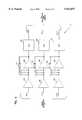
- FIG. 9illustrates a simplified version of the signal processing circuitry 14 for selectively preamplifying and filtering the electrical signals provided in each channel from the infrared energy detector 16.
- the electrical signals from each channel of the infrared energy detector 16(in this case, three channels are illustrated: CO 2 , N 2 O and REF) are passed through respective buffers (54, 56, and 58) prior to application to a respective variable preamplifiers (60, 62, or 64) and then to respective low pass filters (66, 68, and 70).
- the resulting electrical signalsare then sent to a microprocessor (not shown) for calculation of the gas concentration for the gas measured in each channel.
- the resultsare then displayed to a technician on a display device (also not shown).
- the gain of the preamplifiers 60, 62, and 64may be adjusted by manually adjusting PCB jumpers in the jumper connections 72, 74, and 76 in the respective feedback paths so that the feedback signal passes through a different one of the feedback resistors (R1-R9).
- the gain of each of the preamplifiers 60, 62, and 64may be set independent of the gains of the other preamplifiers in the other processing channels, which permits much looser tolerances on the performance specifications of the optical components (light source, detector, and analytical filters).
- independently adjustable gainsmake the analyzer more manufacturable and less costly than if components with tighter performance specifications were required.
- the infrared gas analyzer 10 of the inventionoperates in a conventional manner.
- a sample gas stream taken from the patient's main respiratory airwayis directed to sample cell 18 via tube fitting 20.
- the sample gas streamis typically pumped into the sample cell 18 using a downstream pneumatic device such as a pump (not shown).
- a downstream pneumatic devicesuch as a pump (not shown).
- infrared light from the infrared energy source 25passes through infrared transmissive window 30 into the detection volume 28 and through the gas to be analyzed, which, as noted above, flows through the sample cell in a smooth, laminar flow to improve pneumatic response time.
- the infrared energy detector 16typically contains filters for selectively filtering the attenuated infrared light at the respective characteristic frequencies of the different constituents. Infrared energy detector 16 also converts the received light into electrical signals which pass through the signal processing circuitry of FIG. 9 before being processed in a microprocessor (not shown) into values indicative of the concentrations of the respective measured constituents in the gas flow stream. This information is then presented to the technician via a display (also not shown).
- the signal processing performed on the raw detection signals from the infrared gas analyzer 10generally comprises conditioning the signals using a single stage preamplifier with a variable fixed gain and a 20 Hz low pass filter.
- the fixed gainis variable for each channel by manually adjusting a jumper in a jumper connector 72, 74, or 76 on the PCB 12.
- the infrared energy detector 16may include a thermistor temperature sensor mounted directly underneath a thermopile substrate, the thermistor having a nominal impedance of, e.g., 20 K ⁇ at 25° C.
- the thermistor signalis typically buffered by an amplifier of the signal processing circuitry 14 and preferably can be measured at a pin of the PCB 12.
- unit specific calibration coefficientsare preferably stored in a memory, such as EPROM 15, on the PCB 12.
- a memorysuch as EPROM 15, on the PCB 12.
- such calibration coefficients for a CO 2 and N 2 O infrared gas analyzer 10may include the following:
- Software of a microprocessor of the signal processing circuitry 14typically calculates the gas concentrations of the respective gas constituents as well as other values.
- the microprocessor of the signal processing circuitry 14may compute the concentrations of the measured gases (e.g., CO 2 and N 2 O) by first computing the logarithms and cross product terms (where Ln denotes natural logarithm):
- An . . . Hnare unit specific constants stored in the EPROM 15.
- the processing of the raw detection signals by the infrared gas analyzer 10 of the inventionincorporates the gas concentration computation techniques described by the present inventors in the afore-mentioned patents, including U.S. Pat. No. 5,281,817, the contents of which are hereby incorporated by reference in their entirety.
Landscapes
- Health & Medical Sciences (AREA)
- Physics & Mathematics (AREA)
- Life Sciences & Earth Sciences (AREA)
- Pathology (AREA)
- Spectroscopy & Molecular Physics (AREA)
- General Health & Medical Sciences (AREA)
- Surgery (AREA)
- Public Health (AREA)
- Biomedical Technology (AREA)
- Heart & Thoracic Surgery (AREA)
- Medical Informatics (AREA)
- Molecular Biology (AREA)
- Biophysics (AREA)
- Animal Behavior & Ethology (AREA)
- Pulmonology (AREA)
- Engineering & Computer Science (AREA)
- Veterinary Medicine (AREA)
- Physiology (AREA)
- Chemical & Material Sciences (AREA)
- Analytical Chemistry (AREA)
- Biochemistry (AREA)
- General Physics & Mathematics (AREA)
- Immunology (AREA)
- Investigating Or Analysing Materials By Optical Means (AREA)
Abstract
Description
______________________________________Coefficient Definition______________________________________S/N Serial NumberRt nominal thermistor series resistanceTc1 . . .Tc4 4 constants for the polynomial expansion of the temperature affect on CO.sub.2Tn1 . . .Tn4 4 constants for the polynomial expansion of the temperature affect on N.sub.2 OCoff offset voltage of CO.sub.2 channelNoff offset voltage of N.sub.2 O channelRoff offset voltage of REF channelSc CO.sub.2 /REF Span FactorSn N.sub.2 O/REF Span FactorAc . . .Hc 8 constants for the polynomial expansion of CO.sub.2An . . .Hn 8 constants for the polynomial expansion of N.sub.2 O______________________________________
LC=Ln(Rc)
LN=Ln(Rn)
CP=LC*LN
CO.sub.2 ={Ac+(Bc*LC)+(Cc*LC.sup.2)+(Dc*LC.sup.3)+(Ec*LN)+(Fc*LN.sup.2)+(Gc*LN.sup.3)+(Hc*CP)}*C02TCFN.sub.2 O={An+(Bn*LN)+(Cn*LN.sup.2)+(Dn*LN.sup.3)+(En*LC)+(Fn*LC.sup.2)+(Gn*LC.sup.3)+(Hn*CP)}*N20TCFClaims (11)
Priority Applications (1)
| Application Number | Priority Date | Filing Date | Title |
|---|---|---|---|
| US08/842,812US5932877A (en) | 1997-04-17 | 1997-04-17 | High performance side stream infrared gas analyzer |
Applications Claiming Priority (1)
| Application Number | Priority Date | Filing Date | Title |
|---|---|---|---|
| US08/842,812US5932877A (en) | 1997-04-17 | 1997-04-17 | High performance side stream infrared gas analyzer |
Publications (1)
| Publication Number | Publication Date |
|---|---|
| US5932877Atrue US5932877A (en) | 1999-08-03 |
Family
ID=25288289
Family Applications (1)
| Application Number | Title | Priority Date | Filing Date |
|---|---|---|---|
| US08/842,812Expired - Fee RelatedUS5932877A (en) | 1997-04-17 | 1997-04-17 | High performance side stream infrared gas analyzer |
Country Status (1)
| Country | Link |
|---|---|
| US (1) | US5932877A (en) |
Cited By (34)
| Publication number | Priority date | Publication date | Assignee | Title |
|---|---|---|---|---|
| US6216692B1 (en)* | 1998-06-19 | 2001-04-17 | Nihon Kohden Corporation | Airway adaptor for measurement of gas concentration |
| US6277081B1 (en)* | 1999-05-18 | 2001-08-21 | Invivo Research, Inc. | Anesthetic gas detection apparatus |
| US20020153490A1 (en)* | 2001-03-28 | 2002-10-24 | O'leary Robert | Concentration detection system |
| US20020177232A1 (en)* | 2001-05-23 | 2002-11-28 | Melker Richard J. | Method and apparatus for detecting illicit substances |
| US6534769B1 (en) | 1999-12-31 | 2003-03-18 | Ge Medical Systems Information Technologies, Inc. | Low cost main stream gas analyzer system |
| US20030139681A1 (en)* | 2002-01-22 | 2003-07-24 | Melker Richard J. | Method and apparatus for monitoring intravenous (IV) drug concentration using exhaled breath |
| US20030176804A1 (en)* | 2002-01-22 | 2003-09-18 | Melker Richard J. | Method and apparatus for monitoring respiratory gases during anesthesia |
| US20030191405A1 (en)* | 2002-04-04 | 2003-10-09 | Ric Investments, Inc. | Sidestream gas sampling system with detachable sample cell |
| US20040065835A1 (en)* | 2002-10-08 | 2004-04-08 | Ric Investments, Inc. | Low volume sample cell and gas monitoring system using same |
| US6741887B1 (en) | 2000-12-01 | 2004-05-25 | Ge Medical Systems Information Technologies, Inc. | Apparatus and method for presenting periodic data |
| US20040236242A1 (en)* | 2003-05-22 | 2004-11-25 | Graham James E. | Capnograph system with integral controller |
| US20050012053A1 (en)* | 2003-07-16 | 2005-01-20 | O'leary Robert K. | High frequency infrared radiation source |
| US20050054942A1 (en)* | 2002-01-22 | 2005-03-10 | Melker Richard J. | System and method for therapeutic drug monitoring |
| WO2005059524A1 (en)* | 2003-12-19 | 2005-06-30 | Medair Ab | Liquid or gas sensor and method |
| US20050285055A1 (en)* | 2004-06-29 | 2005-12-29 | Ric Investments, Llc. | Infrared source modulation and system using same |
| US7052854B2 (en) | 2001-05-23 | 2006-05-30 | University Of Florida Research Foundation, Inc. | Application of nanotechnology and sensor technologies for ex-vivo diagnostics |
| US7052468B2 (en) | 2001-05-24 | 2006-05-30 | University Of Florida Research Foundation, Inc. | Method and apparatus for detecting environmental smoke exposure |
| WO2006071171A1 (en)* | 2004-12-29 | 2006-07-06 | Senseair Ab | A gas detecting arrangement |
| US20060249160A1 (en)* | 2005-05-06 | 2006-11-09 | Ric Investments, Llc. | Patient interface with respiratory gas measurement component |
| US20060263916A1 (en)* | 2002-05-08 | 2006-11-23 | Jose Arno | Infrared thermopile detector system for semiconductor process monitoring and control |
| USD593197S1 (en) | 2007-11-14 | 2009-05-26 | Ric Investments, Llc | Face mask |
| US7556039B1 (en) | 2004-02-19 | 2009-07-07 | Ric Investments, Inc. | Sidestream gas sampling system using a capillary tube flow sensor |
| US7820108B2 (en) | 1999-11-08 | 2010-10-26 | University Of Florida Research Foundation, Inc. | Marker detection method and apparatus to monitor drug compliance |
| US7914460B2 (en) | 2006-08-15 | 2011-03-29 | University Of Florida Research Foundation, Inc. | Condensate glucose analyzer |
| US20120074325A1 (en)* | 2010-09-23 | 2012-03-29 | Li-Cor, Inc. | Gas exchange system flow configuration with thermally insulated sample chamber |
| US8211035B2 (en) | 2002-01-22 | 2012-07-03 | University Of Florida Research Foundation, Inc. | System and method for monitoring health using exhaled breath |
| EP2606820A1 (en)* | 2011-12-19 | 2013-06-26 | General Electric Company | Airway adapter and analyzer and method for analyzing at least one property of a respiratory gas |
| CN103292846A (en)* | 2012-02-29 | 2013-09-11 | 深圳迈瑞生物医疗电子股份有限公司 | Gas measuring device |
| US8610072B2 (en) | 2010-09-23 | 2013-12-17 | Li-Cor, Inc. | Gas exchange system flow configuration |
| US8910506B2 (en) | 2010-09-23 | 2014-12-16 | Li-Cor, Inc. | Gas exchange system flow configuration |
| US9375544B2 (en) | 2007-11-14 | 2016-06-28 | Ric Investments, Llc | Face mask |
| WO2020183466A1 (en)* | 2019-03-12 | 2020-09-17 | Picodya Technologies Ltd. | Matrix droplet extruder, sample holder and sample analysis system |
| US20210236707A1 (en)* | 2018-05-24 | 2021-08-05 | Eurosets S.R.L. | Device for the measurement of carbon dioxide in a working gas |
| CN115684009A (en)* | 2022-08-20 | 2023-02-03 | 苏州市翼锋电子科技有限公司 | Small infrared gas sensor and working principle |
Citations (14)
| Publication number | Priority date | Publication date | Assignee | Title |
|---|---|---|---|---|
| US3725658A (en)* | 1971-01-18 | 1973-04-03 | Trw Inc | Apparatus and method for continuously detecting oxygen in a gas stream |
| US4177381A (en)* | 1974-09-27 | 1979-12-04 | Andros Incorporated | Gas analyzer sample cell |
| US4297871A (en)* | 1978-11-03 | 1981-11-03 | Wright Basil M | Gas sampling devices |
| US4558708A (en)* | 1984-10-24 | 1985-12-17 | Tri-Med, Inc. | Patient's airway adapter to withdraw a patient's gas samples for testing free of sputum mucus and/or condensed water, by utilizing a hollow cylindrical hydrophobic liquid baffle |
| US4692621A (en)* | 1985-10-11 | 1987-09-08 | Andros Anlayzers Incorporated | Digital anesthetic agent analyzer |
| US4852583A (en)* | 1987-01-16 | 1989-08-01 | Spacelabs, Inc. | Airway adapter |
| US5081998A (en)* | 1989-09-01 | 1992-01-21 | Critikon, Inc. | Optically stabilized infrared energy detector |
| US5095915A (en)* | 1990-03-19 | 1992-03-17 | Target Therapeutics | Guidewire with flexible distal tip |
| US5247185A (en)* | 1991-10-28 | 1993-09-21 | Critikon, Inc. | Regulated infrared source |
| US5281817A (en)* | 1989-09-01 | 1994-01-25 | Critikon, Inc. | Method of selecting an optical filter for a shutterless optically stabilized capnograph |
| US5282473A (en)* | 1992-11-10 | 1994-02-01 | Critikon, Inc. | Sidestream infrared gas analyzer requiring small sample volumes |
| US5296706A (en)* | 1992-12-02 | 1994-03-22 | Critikon, Inc. | Shutterless mainstream discriminating anesthetic agent analyzer |
| US5464982A (en)* | 1994-03-21 | 1995-11-07 | Andros Incorporated | Respiratory gas analyzer |
| US5583339A (en)* | 1992-11-20 | 1996-12-10 | Sensors, Inc. | Infrared method and apparatus for measuring gas concentration of a plurality of component gases in a sample |
- 1997
- 1997-04-17USUS08/842,812patent/US5932877A/ennot_activeExpired - Fee Related
Patent Citations (14)
| Publication number | Priority date | Publication date | Assignee | Title |
|---|---|---|---|---|
| US3725658A (en)* | 1971-01-18 | 1973-04-03 | Trw Inc | Apparatus and method for continuously detecting oxygen in a gas stream |
| US4177381A (en)* | 1974-09-27 | 1979-12-04 | Andros Incorporated | Gas analyzer sample cell |
| US4297871A (en)* | 1978-11-03 | 1981-11-03 | Wright Basil M | Gas sampling devices |
| US4558708A (en)* | 1984-10-24 | 1985-12-17 | Tri-Med, Inc. | Patient's airway adapter to withdraw a patient's gas samples for testing free of sputum mucus and/or condensed water, by utilizing a hollow cylindrical hydrophobic liquid baffle |
| US4692621A (en)* | 1985-10-11 | 1987-09-08 | Andros Anlayzers Incorporated | Digital anesthetic agent analyzer |
| US4852583A (en)* | 1987-01-16 | 1989-08-01 | Spacelabs, Inc. | Airway adapter |
| US5081998A (en)* | 1989-09-01 | 1992-01-21 | Critikon, Inc. | Optically stabilized infrared energy detector |
| US5281817A (en)* | 1989-09-01 | 1994-01-25 | Critikon, Inc. | Method of selecting an optical filter for a shutterless optically stabilized capnograph |
| US5095915A (en)* | 1990-03-19 | 1992-03-17 | Target Therapeutics | Guidewire with flexible distal tip |
| US5247185A (en)* | 1991-10-28 | 1993-09-21 | Critikon, Inc. | Regulated infrared source |
| US5282473A (en)* | 1992-11-10 | 1994-02-01 | Critikon, Inc. | Sidestream infrared gas analyzer requiring small sample volumes |
| US5583339A (en)* | 1992-11-20 | 1996-12-10 | Sensors, Inc. | Infrared method and apparatus for measuring gas concentration of a plurality of component gases in a sample |
| US5296706A (en)* | 1992-12-02 | 1994-03-22 | Critikon, Inc. | Shutterless mainstream discriminating anesthetic agent analyzer |
| US5464982A (en)* | 1994-03-21 | 1995-11-07 | Andros Incorporated | Respiratory gas analyzer |
Cited By (59)
| Publication number | Priority date | Publication date | Assignee | Title |
|---|---|---|---|---|
| US6216692B1 (en)* | 1998-06-19 | 2001-04-17 | Nihon Kohden Corporation | Airway adaptor for measurement of gas concentration |
| US6277081B1 (en)* | 1999-05-18 | 2001-08-21 | Invivo Research, Inc. | Anesthetic gas detection apparatus |
| US7820108B2 (en) | 1999-11-08 | 2010-10-26 | University Of Florida Research Foundation, Inc. | Marker detection method and apparatus to monitor drug compliance |
| US6534769B1 (en) | 1999-12-31 | 2003-03-18 | Ge Medical Systems Information Technologies, Inc. | Low cost main stream gas analyzer system |
| US6741887B1 (en) | 2000-12-01 | 2004-05-25 | Ge Medical Systems Information Technologies, Inc. | Apparatus and method for presenting periodic data |
| US20020153490A1 (en)* | 2001-03-28 | 2002-10-24 | O'leary Robert | Concentration detection system |
| US20020177232A1 (en)* | 2001-05-23 | 2002-11-28 | Melker Richard J. | Method and apparatus for detecting illicit substances |
| US7052854B2 (en) | 2001-05-23 | 2006-05-30 | University Of Florida Research Foundation, Inc. | Application of nanotechnology and sensor technologies for ex-vivo diagnostics |
| US7052468B2 (en) | 2001-05-24 | 2006-05-30 | University Of Florida Research Foundation, Inc. | Method and apparatus for detecting environmental smoke exposure |
| US20030176804A1 (en)* | 2002-01-22 | 2003-09-18 | Melker Richard J. | Method and apparatus for monitoring respiratory gases during anesthesia |
| US7104963B2 (en)* | 2002-01-22 | 2006-09-12 | University Of Florida Research Foundation, Inc. | Method and apparatus for monitoring intravenous (IV) drug concentration using exhaled breath |
| US8211035B2 (en) | 2002-01-22 | 2012-07-03 | University Of Florida Research Foundation, Inc. | System and method for monitoring health using exhaled breath |
| US6981947B2 (en) | 2002-01-22 | 2006-01-03 | University Of Florida Research Foundation, Inc. | Method and apparatus for monitoring respiratory gases during anesthesia |
| US20050054942A1 (en)* | 2002-01-22 | 2005-03-10 | Melker Richard J. | System and method for therapeutic drug monitoring |
| US20030139681A1 (en)* | 2002-01-22 | 2003-07-24 | Melker Richard J. | Method and apparatus for monitoring intravenous (IV) drug concentration using exhaled breath |
| US8282570B2 (en) | 2002-04-04 | 2012-10-09 | Ric Investments, Llc | Sidestream gas sampling system with detachable sample cell |
| US20080200825A1 (en)* | 2002-04-04 | 2008-08-21 | Ric Investments, Llc | Sidestream Gas Sampling System with Detachable Sample Cell |
| US7341563B2 (en) | 2002-04-04 | 2008-03-11 | Ric Investments, Llc | Sidestream gas sampling system with detachable sample cell |
| US20030191405A1 (en)* | 2002-04-04 | 2003-10-09 | Ric Investments, Inc. | Sidestream gas sampling system with detachable sample cell |
| WO2003085380A1 (en) | 2002-04-04 | 2003-10-16 | Ric Investments, Inc. | Sidestream gas sampling system with detachable sample cell |
| US7723685B2 (en)* | 2002-05-08 | 2010-05-25 | Advanced Technology Materials, Inc. | Monitoring system comprising infrared thermopile detector |
| US20090039266A1 (en)* | 2002-05-08 | 2009-02-12 | Advanced Technology Materials, Inc. | Monitoring system comprising infrared thermopile detector |
| US20060263916A1 (en)* | 2002-05-08 | 2006-11-23 | Jose Arno | Infrared thermopile detector system for semiconductor process monitoring and control |
| US7294839B2 (en)* | 2002-10-08 | 2007-11-13 | Ric Investements, Inc. | Low volume sample cell and gas monitoring system using same |
| US20040065835A1 (en)* | 2002-10-08 | 2004-04-08 | Ric Investments, Inc. | Low volume sample cell and gas monitoring system using same |
| US20040236242A1 (en)* | 2003-05-22 | 2004-11-25 | Graham James E. | Capnograph system with integral controller |
| US20050012053A1 (en)* | 2003-07-16 | 2005-01-20 | O'leary Robert K. | High frequency infrared radiation source |
| US6878938B2 (en) | 2003-07-16 | 2005-04-12 | Perkinelmer, Inc. | High frequency infrared radiation source |
| US20070101800A1 (en)* | 2003-12-19 | 2007-05-10 | Johan Stenberg | Liquid or gas sensor and method |
| US7525093B2 (en) | 2003-12-19 | 2009-04-28 | Medair Ab | Liquid or gas sensor and method |
| WO2005059524A1 (en)* | 2003-12-19 | 2005-06-30 | Medair Ab | Liquid or gas sensor and method |
| US7556039B1 (en) | 2004-02-19 | 2009-07-07 | Ric Investments, Inc. | Sidestream gas sampling system using a capillary tube flow sensor |
| US7291851B2 (en) | 2004-06-29 | 2007-11-06 | Ric Investments, Llc | Infrared source modulation and system using same |
| WO2006091218A3 (en)* | 2004-06-29 | 2007-10-18 | Ric Investments Llc | Infrared source modulation and system using same |
| US20050285055A1 (en)* | 2004-06-29 | 2005-12-29 | Ric Investments, Llc. | Infrared source modulation and system using same |
| US8257655B2 (en) | 2004-12-29 | 2012-09-04 | Senseair Ab | Gas detecting arrangement |
| US20080019877A1 (en)* | 2004-12-29 | 2008-01-24 | Martin Hans E G | Gas Detecting Arrangement |
| CN100549674C (en)* | 2004-12-29 | 2009-10-14 | 森谢尔公司 | Gas detection device |
| WO2006071171A1 (en)* | 2004-12-29 | 2006-07-06 | Senseair Ab | A gas detecting arrangement |
| US7568483B2 (en) | 2005-05-06 | 2009-08-04 | Ric Investments, Llc | Patient interface with respiratory gas measurement component |
| WO2006122092A2 (en) | 2005-05-06 | 2006-11-16 | Ric Investments, Llc | Patient interface with respiratory gas measurement component |
| US20060249160A1 (en)* | 2005-05-06 | 2006-11-09 | Ric Investments, Llc. | Patient interface with respiratory gas measurement component |
| US7914460B2 (en) | 2006-08-15 | 2011-03-29 | University Of Florida Research Foundation, Inc. | Condensate glucose analyzer |
| US9375544B2 (en) | 2007-11-14 | 2016-06-28 | Ric Investments, Llc | Face mask |
| USD593197S1 (en) | 2007-11-14 | 2009-05-26 | Ric Investments, Llc | Face mask |
| US10245405B2 (en) | 2007-11-14 | 2019-04-02 | Ric Investments, Llc | Face mask |
| US8610072B2 (en) | 2010-09-23 | 2013-12-17 | Li-Cor, Inc. | Gas exchange system flow configuration |
| US20120074325A1 (en)* | 2010-09-23 | 2012-03-29 | Li-Cor, Inc. | Gas exchange system flow configuration with thermally insulated sample chamber |
| US8692202B2 (en)* | 2010-09-23 | 2014-04-08 | Li-Cor, Inc. | Gas exchange system flow configuration with thermally insulated sample chamber |
| US8910506B2 (en) | 2010-09-23 | 2014-12-16 | Li-Cor, Inc. | Gas exchange system flow configuration |
| US9482653B2 (en) | 2010-09-23 | 2016-11-01 | Li-Cor, Inc. | Gas exchange system flow configuration |
| EP2606820A1 (en)* | 2011-12-19 | 2013-06-26 | General Electric Company | Airway adapter and analyzer and method for analyzing at least one property of a respiratory gas |
| CN103292846B (en)* | 2012-02-29 | 2015-11-25 | 深圳迈瑞生物医疗电子股份有限公司 | A kind of gas measurement device |
| CN103292846A (en)* | 2012-02-29 | 2013-09-11 | 深圳迈瑞生物医疗电子股份有限公司 | Gas measuring device |
| US20210236707A1 (en)* | 2018-05-24 | 2021-08-05 | Eurosets S.R.L. | Device for the measurement of carbon dioxide in a working gas |
| US12246120B2 (en)* | 2018-05-24 | 2025-03-11 | Eurosets S.R.L. | Device for the measurement of carbon dioxide in a working gas |
| WO2020183466A1 (en)* | 2019-03-12 | 2020-09-17 | Picodya Technologies Ltd. | Matrix droplet extruder, sample holder and sample analysis system |
| US11061045B2 (en) | 2019-03-12 | 2021-07-13 | Picodya Technologies Ltd. | Sample analysis system and method |
| CN115684009A (en)* | 2022-08-20 | 2023-02-03 | 苏州市翼锋电子科技有限公司 | Small infrared gas sensor and working principle |
Similar Documents
| Publication | Publication Date | Title |
|---|---|---|
| US5932877A (en) | High performance side stream infrared gas analyzer | |
| US5282473A (en) | Sidestream infrared gas analyzer requiring small sample volumes | |
| US5326973A (en) | Device for gas analysis | |
| US5468961A (en) | Infrared gas analyser and humidity sensor | |
| US5464982A (en) | Respiratory gas analyzer | |
| EP1332346B1 (en) | Respiratory gas analyzer | |
| US7432508B2 (en) | Gas measurement system | |
| US5281817A (en) | Method of selecting an optical filter for a shutterless optically stabilized capnograph | |
| US5401966A (en) | Spectrophotometric sensor assembly including a microlamp | |
| US11674900B2 (en) | NDIR sensor, sampling method and system for breath analysis | |
| US7294839B2 (en) | Low volume sample cell and gas monitoring system using same | |
| US6410918B1 (en) | Diffusion-type NDIR gas analyzer with improved response time due to convection flow | |
| AU753912B2 (en) | Diffusion-type NDIR gas analyzer with convection flow | |
| AU637827B2 (en) | Shutterless optically stabilized capnograph | |
| CN117679010A (en) | Gas concentration detection device | |
| WO1993009413A2 (en) | Filter selection for shutterless optically stabilized capnograph | |
| Burte et al. | Microsystems for measurement and dosage of volatile anesthetics and respirative gases in anesthetic equipment | |
| FI101428B (en) | Small non-dispersive gas measuring sensor |
Legal Events
| Date | Code | Title | Description |
|---|---|---|---|
| AS | Assignment | Owner name:SQUARE ONE TECHNOLOGY, INC., COLORADO Free format text:ASSIGNMENT OF ASSIGNORS INTEREST;ASSIGNORS:BRAIG, JAMES R.;GOLDBERGER, DANIEL S.;REEL/FRAME:008552/0202 Effective date:19970415 | |
| CC | Certificate of correction | ||
| AS | Assignment | Owner name:UDT SENSORS, INC., CALIFORNIA Free format text:ASSIGNMENT OF ASSIGNORS INTEREST;ASSIGNOR:SQUARE ONE TECHNOLOGY;REEL/FRAME:011190/0220 Effective date:20000831 | |
| AS | Assignment | Owner name:UDT SENSORS, INC., A CALIFORNIA CORPORATION, CALIF Free format text:ASSIGNMENT OF ASSIGNORS INTEREST;ASSIGNOR:SQUARE ONE TECHNOLOGY, INC., A DELAWARE CORPORATION;REEL/FRAME:011231/0045 Effective date:20000831 | |
| REMI | Maintenance fee reminder mailed | ||
| LAPS | Lapse for failure to pay maintenance fees | ||
| STCH | Information on status: patent discontinuation | Free format text:PATENT EXPIRED DUE TO NONPAYMENT OF MAINTENANCE FEES UNDER 37 CFR 1.362 | |
| FP | Lapsed due to failure to pay maintenance fee | Effective date:20030803 | |
| AS | Assignment | Owner name:BANK OF THE WEST, A CALIFORNIA BANKING CORPORATION Free format text:SECURITY AGREEMENT;ASSIGNOR:UDT SENSORS, INC.;REEL/FRAME:016182/0885 Effective date:20050624 | |
| AS | Assignment | Owner name:BANK OF THE WEST, CALIFORNIA Free format text:SECURITY AGREEMENT;ASSIGNOR:OSI OPTOELECTRONICS, INC., A CALIFORNIA CORPORATION;REEL/FRAME:017957/0957 Effective date:20060718 |