US5932181A - Natural gas-using hydrogen generator - Google Patents
Natural gas-using hydrogen generatorDownload PDFInfo
- Publication number
- US5932181A US5932181AUS08/988,364US98836497AUS5932181AUS 5932181 AUS5932181 AUS 5932181AUS 98836497 AUS98836497 AUS 98836497AUS 5932181 AUS5932181 AUS 5932181A
- Authority
- US
- United States
- Prior art keywords
- natural gas
- reformer
- pipe line
- combustion
- hydrogen generator
- Prior art date
- Legal status (The legal status is an assumption and is not a legal conclusion. Google has not performed a legal analysis and makes no representation as to the accuracy of the status listed.)
- Expired - Fee Related
Links
- UFHFLCQGNIYNRP-UHFFFAOYSA-NHydrogenChemical compound[H][H]UFHFLCQGNIYNRP-UHFFFAOYSA-N0.000titleclaimsabstractdescription50
- 239000001257hydrogenSubstances0.000titleclaimsabstractdescription49
- 229910052739hydrogenInorganic materials0.000titleclaimsabstractdescription49
- VNWKTOKETHGBQD-UHFFFAOYSA-NmethaneChemical compoundCVNWKTOKETHGBQD-UHFFFAOYSA-N0.000claimsabstractdescription73
- 238000006477desulfuration reactionMethods0.000claimsabstractdescription43
- 230000023556desulfurizationEffects0.000claimsabstractdescription43
- 239000003345natural gasSubstances0.000claimsabstractdescription34
- 239000000567combustion gasSubstances0.000claimsabstractdescription29
- 239000007789gasSubstances0.000claimsabstractdescription29
- 238000006243chemical reactionMethods0.000claimsabstractdescription24
- 238000002485combustion reactionMethods0.000claimsdescription30
- 239000003054catalystSubstances0.000claimsdescription28
- 239000000446fuelSubstances0.000claimsdescription25
- 238000002407reformingMethods0.000claimsdescription21
- 238000002347injectionMethods0.000claimsdescription13
- 239000007924injectionSubstances0.000claimsdescription13
- KDLHZDBZIXYQEI-UHFFFAOYSA-NPalladiumChemical compound[Pd]KDLHZDBZIXYQEI-UHFFFAOYSA-N0.000claimsdescription12
- XLYOFNOQVPJJNP-UHFFFAOYSA-NwaterSubstancesOXLYOFNOQVPJJNP-UHFFFAOYSA-N0.000claimsdescription9
- 229910052763palladiumInorganic materials0.000claimsdescription6
- RWSOTUBLDIXVET-UHFFFAOYSA-NDihydrogen sulfideChemical compoundSRWSOTUBLDIXVET-UHFFFAOYSA-N0.000claimsdescription3
- 238000010521absorption reactionMethods0.000claimsdescription3
- 229910052751metalInorganic materials0.000claimsdescription3
- 239000002184metalSubstances0.000claimsdescription3
- 229910000037hydrogen sulfideInorganic materials0.000claimsdescription2
- 238000012544monitoring processMethods0.000claims2
- 238000001179sorption measurementMethods0.000claims1
- 239000008239natural waterSubstances0.000abstract1
- 238000000034methodMethods0.000description8
- UGFAIRIUMAVXCW-UHFFFAOYSA-NCarbon monoxideChemical compound[O+]#[C-]UGFAIRIUMAVXCW-UHFFFAOYSA-N0.000description5
- 229910002091carbon monoxideInorganic materials0.000description5
- 238000004519manufacturing processMethods0.000description5
- 238000000629steam reformingMethods0.000description5
- 229930195733hydrocarbonNatural products0.000description3
- 150000002430hydrocarbonsChemical class0.000description3
- PXHVJJICTQNCMI-UHFFFAOYSA-NnickelSubstances[Ni]PXHVJJICTQNCMI-UHFFFAOYSA-N0.000description3
- IJGRMHOSHXDMSA-UHFFFAOYSA-NAtomic nitrogenChemical compoundN#NIJGRMHOSHXDMSA-UHFFFAOYSA-N0.000description2
- ATUOYWHBWRKTHZ-UHFFFAOYSA-NPropaneChemical compoundCCCATUOYWHBWRKTHZ-UHFFFAOYSA-N0.000description2
- 238000002453autothermal reformingMethods0.000description2
- 238000012423maintenanceMethods0.000description2
- 239000000203mixtureSubstances0.000description2
- 230000003647oxidationEffects0.000description2
- 238000007254oxidation reactionMethods0.000description2
- 230000000149penetrating effectEffects0.000description2
- 150000003464sulfur compoundsChemical class0.000description2
- 239000004215Carbon black (E152)Substances0.000description1
- NINIDFKCEFEMDL-UHFFFAOYSA-NSulfurChemical compound[S]NINIDFKCEFEMDL-UHFFFAOYSA-N0.000description1
- 239000003463adsorbentSubstances0.000description1
- QVGXLLKOCUKJST-UHFFFAOYSA-Natomic oxygenChemical compound[O]QVGXLLKOCUKJST-UHFFFAOYSA-N0.000description1
- 239000001273butaneSubstances0.000description1
- 239000000571cokeSubstances0.000description1
- 239000000498cooling waterSubstances0.000description1
- 230000002542deteriorative effectEffects0.000description1
- 238000009434installationMethods0.000description1
- 239000012774insulation materialSubstances0.000description1
- 239000000463materialSubstances0.000description1
- 230000004048modificationEffects0.000description1
- 238000012986modificationMethods0.000description1
- 239000002808molecular sieveSubstances0.000description1
- IJDNQMDRQITEOD-UHFFFAOYSA-Nn-butaneChemical compoundCCCCIJDNQMDRQITEOD-UHFFFAOYSA-N0.000description1
- OFBQJSOFQDEBGM-UHFFFAOYSA-Nn-pentaneNatural productsCCCCCOFBQJSOFQDEBGM-UHFFFAOYSA-N0.000description1
- 229910052759nickelInorganic materials0.000description1
- 229910052757nitrogenInorganic materials0.000description1
- 239000001301oxygenSubstances0.000description1
- 229910052760oxygenInorganic materials0.000description1
- 239000010970precious metalSubstances0.000description1
- 239000001294propaneSubstances0.000description1
- 239000002994raw materialSubstances0.000description1
- 238000011084recoveryMethods0.000description1
- 238000007670refiningMethods0.000description1
- URGAHOPLAPQHLN-UHFFFAOYSA-Nsodium aluminosilicateChemical compound[Na+].[Al+3].[O-][Si]([O-])=O.[O-][Si]([O-])=OURGAHOPLAPQHLN-UHFFFAOYSA-N0.000description1
- 229910052717sulfurInorganic materials0.000description1
- 239000011593sulfurSubstances0.000description1
Images


Classifications
- B—PERFORMING OPERATIONS; TRANSPORTING
- B01—PHYSICAL OR CHEMICAL PROCESSES OR APPARATUS IN GENERAL
- B01J—CHEMICAL OR PHYSICAL PROCESSES, e.g. CATALYSIS OR COLLOID CHEMISTRY; THEIR RELEVANT APPARATUS
- B01J7/00—Apparatus for generating gases
- C—CHEMISTRY; METALLURGY
- C01—INORGANIC CHEMISTRY
- C01B—NON-METALLIC ELEMENTS; COMPOUNDS THEREOF; METALLOIDS OR COMPOUNDS THEREOF NOT COVERED BY SUBCLASS C01C
- C01B3/00—Hydrogen; Gaseous mixtures containing hydrogen; Separation of hydrogen from mixtures containing it; Purification of hydrogen
- C01B3/50—Separation of hydrogen or hydrogen containing gases from gaseous mixtures, e.g. purification
- C01B3/56—Separation of hydrogen or hydrogen containing gases from gaseous mixtures, e.g. purification by contacting with solids; Regeneration of used solids
- B—PERFORMING OPERATIONS; TRANSPORTING
- B01—PHYSICAL OR CHEMICAL PROCESSES OR APPARATUS IN GENERAL
- B01D—SEPARATION
- B01D53/00—Separation of gases or vapours; Recovering vapours of volatile solvents from gases; Chemical or biological purification of waste gases, e.g. engine exhaust gases, smoke, fumes, flue gases, aerosols
- B01D53/34—Chemical or biological purification of waste gases
- B01D53/46—Removing components of defined structure
- B01D53/48—Sulfur compounds
- B—PERFORMING OPERATIONS; TRANSPORTING
- B01—PHYSICAL OR CHEMICAL PROCESSES OR APPARATUS IN GENERAL
- B01J—CHEMICAL OR PHYSICAL PROCESSES, e.g. CATALYSIS OR COLLOID CHEMISTRY; THEIR RELEVANT APPARATUS
- B01J19/00—Chemical, physical or physico-chemical processes in general; Their relevant apparatus
- B01J19/0006—Controlling or regulating processes
- B01J19/0013—Controlling the temperature of the process
- B—PERFORMING OPERATIONS; TRANSPORTING
- B01—PHYSICAL OR CHEMICAL PROCESSES OR APPARATUS IN GENERAL
- B01J—CHEMICAL OR PHYSICAL PROCESSES, e.g. CATALYSIS OR COLLOID CHEMISTRY; THEIR RELEVANT APPARATUS
- B01J8/00—Chemical or physical processes in general, conducted in the presence of fluids and solid particles; Apparatus for such processes
- B01J8/02—Chemical or physical processes in general, conducted in the presence of fluids and solid particles; Apparatus for such processes with stationary particles, e.g. in fixed beds
- B01J8/0242—Chemical or physical processes in general, conducted in the presence of fluids and solid particles; Apparatus for such processes with stationary particles, e.g. in fixed beds the fluid flow within the bed being predominantly vertical
- B01J8/0257—Chemical or physical processes in general, conducted in the presence of fluids and solid particles; Apparatus for such processes with stationary particles, e.g. in fixed beds the fluid flow within the bed being predominantly vertical in a cylindrical annular shaped bed
- B—PERFORMING OPERATIONS; TRANSPORTING
- B01—PHYSICAL OR CHEMICAL PROCESSES OR APPARATUS IN GENERAL
- B01J—CHEMICAL OR PHYSICAL PROCESSES, e.g. CATALYSIS OR COLLOID CHEMISTRY; THEIR RELEVANT APPARATUS
- B01J8/00—Chemical or physical processes in general, conducted in the presence of fluids and solid particles; Apparatus for such processes
- B01J8/02—Chemical or physical processes in general, conducted in the presence of fluids and solid particles; Apparatus for such processes with stationary particles, e.g. in fixed beds
- B01J8/0285—Heating or cooling the reactor
- B—PERFORMING OPERATIONS; TRANSPORTING
- B01—PHYSICAL OR CHEMICAL PROCESSES OR APPARATUS IN GENERAL
- B01J—CHEMICAL OR PHYSICAL PROCESSES, e.g. CATALYSIS OR COLLOID CHEMISTRY; THEIR RELEVANT APPARATUS
- B01J8/00—Chemical or physical processes in general, conducted in the presence of fluids and solid particles; Apparatus for such processes
- B01J8/02—Chemical or physical processes in general, conducted in the presence of fluids and solid particles; Apparatus for such processes with stationary particles, e.g. in fixed beds
- B01J8/04—Chemical or physical processes in general, conducted in the presence of fluids and solid particles; Apparatus for such processes with stationary particles, e.g. in fixed beds the fluid passing successively through two or more beds
- B01J8/0446—Chemical or physical processes in general, conducted in the presence of fluids and solid particles; Apparatus for such processes with stationary particles, e.g. in fixed beds the fluid passing successively through two or more beds the flow within the beds being predominantly vertical
- B01J8/0449—Chemical or physical processes in general, conducted in the presence of fluids and solid particles; Apparatus for such processes with stationary particles, e.g. in fixed beds the fluid passing successively through two or more beds the flow within the beds being predominantly vertical in two or more cylindrical beds
- B01J8/0453—Chemical or physical processes in general, conducted in the presence of fluids and solid particles; Apparatus for such processes with stationary particles, e.g. in fixed beds the fluid passing successively through two or more beds the flow within the beds being predominantly vertical in two or more cylindrical beds the beds being superimposed one above the other
- B—PERFORMING OPERATIONS; TRANSPORTING
- B01—PHYSICAL OR CHEMICAL PROCESSES OR APPARATUS IN GENERAL
- B01J—CHEMICAL OR PHYSICAL PROCESSES, e.g. CATALYSIS OR COLLOID CHEMISTRY; THEIR RELEVANT APPARATUS
- B01J8/00—Chemical or physical processes in general, conducted in the presence of fluids and solid particles; Apparatus for such processes
- B01J8/02—Chemical or physical processes in general, conducted in the presence of fluids and solid particles; Apparatus for such processes with stationary particles, e.g. in fixed beds
- B01J8/04—Chemical or physical processes in general, conducted in the presence of fluids and solid particles; Apparatus for such processes with stationary particles, e.g. in fixed beds the fluid passing successively through two or more beds
- B01J8/0496—Heating or cooling the reactor
- C—CHEMISTRY; METALLURGY
- C01—INORGANIC CHEMISTRY
- C01B—NON-METALLIC ELEMENTS; COMPOUNDS THEREOF; METALLOIDS OR COMPOUNDS THEREOF NOT COVERED BY SUBCLASS C01C
- C01B3/00—Hydrogen; Gaseous mixtures containing hydrogen; Separation of hydrogen from mixtures containing it; Purification of hydrogen
- C01B3/02—Production of hydrogen or of gaseous mixtures containing a substantial proportion of hydrogen
- C01B3/32—Production of hydrogen or of gaseous mixtures containing a substantial proportion of hydrogen by reaction of gaseous or liquid organic compounds with gasifying agents, e.g. water, carbon dioxide, air
- C01B3/34—Production of hydrogen or of gaseous mixtures containing a substantial proportion of hydrogen by reaction of gaseous or liquid organic compounds with gasifying agents, e.g. water, carbon dioxide, air by reaction of hydrocarbons with gasifying agents
- C01B3/48—Production of hydrogen or of gaseous mixtures containing a substantial proportion of hydrogen by reaction of gaseous or liquid organic compounds with gasifying agents, e.g. water, carbon dioxide, air by reaction of hydrocarbons with gasifying agents followed by reaction of water vapour with carbon monoxide
- B—PERFORMING OPERATIONS; TRANSPORTING
- B01—PHYSICAL OR CHEMICAL PROCESSES OR APPARATUS IN GENERAL
- B01D—SEPARATION
- B01D2253/00—Adsorbents used in seperation treatment of gases and vapours
- B01D2253/10—Inorganic adsorbents
- B01D2253/106—Silica or silicates
- B01D2253/108—Zeolites
- B—PERFORMING OPERATIONS; TRANSPORTING
- B01—PHYSICAL OR CHEMICAL PROCESSES OR APPARATUS IN GENERAL
- B01D—SEPARATION
- B01D2253/00—Adsorbents used in seperation treatment of gases and vapours
- B01D2253/10—Inorganic adsorbents
- B01D2253/116—Molecular sieves other than zeolites
- B—PERFORMING OPERATIONS; TRANSPORTING
- B01—PHYSICAL OR CHEMICAL PROCESSES OR APPARATUS IN GENERAL
- B01D—SEPARATION
- B01D2256/00—Main component in the product gas stream after treatment
- B01D2256/16—Hydrogen
- B—PERFORMING OPERATIONS; TRANSPORTING
- B01—PHYSICAL OR CHEMICAL PROCESSES OR APPARATUS IN GENERAL
- B01D—SEPARATION
- B01D2257/00—Components to be removed
- B01D2257/50—Carbon oxides
- B01D2257/502—Carbon monoxide
- B—PERFORMING OPERATIONS; TRANSPORTING
- B01—PHYSICAL OR CHEMICAL PROCESSES OR APPARATUS IN GENERAL
- B01D—SEPARATION
- B01D2257/00—Components to be removed
- B01D2257/50—Carbon oxides
- B01D2257/504—Carbon dioxide
- B—PERFORMING OPERATIONS; TRANSPORTING
- B01—PHYSICAL OR CHEMICAL PROCESSES OR APPARATUS IN GENERAL
- B01D—SEPARATION
- B01D2257/00—Components to be removed
- B01D2257/70—Organic compounds not provided for in groups B01D2257/00 - B01D2257/602
- B01D2257/702—Hydrocarbons
- B01D2257/7022—Aliphatic hydrocarbons
- B01D2257/7025—Methane
- B—PERFORMING OPERATIONS; TRANSPORTING
- B01—PHYSICAL OR CHEMICAL PROCESSES OR APPARATUS IN GENERAL
- B01D—SEPARATION
- B01D2257/00—Components to be removed
- B01D2257/80—Water
- B—PERFORMING OPERATIONS; TRANSPORTING
- B01—PHYSICAL OR CHEMICAL PROCESSES OR APPARATUS IN GENERAL
- B01D—SEPARATION
- B01D2259/00—Type of treatment
- B01D2259/40—Further details for adsorption processes and devices
- B01D2259/40001—Methods relating to additional, e.g. intermediate, treatment of process gas
- B—PERFORMING OPERATIONS; TRANSPORTING
- B01—PHYSICAL OR CHEMICAL PROCESSES OR APPARATUS IN GENERAL
- B01D—SEPARATION
- B01D53/00—Separation of gases or vapours; Recovering vapours of volatile solvents from gases; Chemical or biological purification of waste gases, e.g. engine exhaust gases, smoke, fumes, flue gases, aerosols
- B01D53/02—Separation of gases or vapours; Recovering vapours of volatile solvents from gases; Chemical or biological purification of waste gases, e.g. engine exhaust gases, smoke, fumes, flue gases, aerosols by adsorption, e.g. preparative gas chromatography
- B01D53/04—Separation of gases or vapours; Recovering vapours of volatile solvents from gases; Chemical or biological purification of waste gases, e.g. engine exhaust gases, smoke, fumes, flue gases, aerosols by adsorption, e.g. preparative gas chromatography with stationary adsorbents
- B01D53/047—Pressure swing adsorption
- B01D53/0476—Vacuum pressure swing adsorption
- B—PERFORMING OPERATIONS; TRANSPORTING
- B01—PHYSICAL OR CHEMICAL PROCESSES OR APPARATUS IN GENERAL
- B01D—SEPARATION
- B01D53/00—Separation of gases or vapours; Recovering vapours of volatile solvents from gases; Chemical or biological purification of waste gases, e.g. engine exhaust gases, smoke, fumes, flue gases, aerosols
- B01D53/26—Drying gases or vapours
- B01D53/261—Drying gases or vapours by adsorption
- B—PERFORMING OPERATIONS; TRANSPORTING
- B01—PHYSICAL OR CHEMICAL PROCESSES OR APPARATUS IN GENERAL
- B01J—CHEMICAL OR PHYSICAL PROCESSES, e.g. CATALYSIS OR COLLOID CHEMISTRY; THEIR RELEVANT APPARATUS
- B01J2219/00—Chemical, physical or physico-chemical processes in general; Their relevant apparatus
- B01J2219/00049—Controlling or regulating processes
- B01J2219/00051—Controlling the temperature
- B01J2219/00074—Controlling the temperature by indirect heating or cooling employing heat exchange fluids
- B01J2219/00087—Controlling the temperature by indirect heating or cooling employing heat exchange fluids with heat exchange elements outside the reactor
- B01J2219/00103—Controlling the temperature by indirect heating or cooling employing heat exchange fluids with heat exchange elements outside the reactor in a heat exchanger separate from the reactor
- B—PERFORMING OPERATIONS; TRANSPORTING
- B01—PHYSICAL OR CHEMICAL PROCESSES OR APPARATUS IN GENERAL
- B01J—CHEMICAL OR PHYSICAL PROCESSES, e.g. CATALYSIS OR COLLOID CHEMISTRY; THEIR RELEVANT APPARATUS
- B01J2219/00—Chemical, physical or physico-chemical processes in general; Their relevant apparatus
- B01J2219/00049—Controlling or regulating processes
- B01J2219/00051—Controlling the temperature
- B01J2219/0015—Controlling the temperature by thermal insulation means
- B01J2219/00155—Controlling the temperature by thermal insulation means using insulating materials or refractories
- B—PERFORMING OPERATIONS; TRANSPORTING
- B01—PHYSICAL OR CHEMICAL PROCESSES OR APPARATUS IN GENERAL
- B01J—CHEMICAL OR PHYSICAL PROCESSES, e.g. CATALYSIS OR COLLOID CHEMISTRY; THEIR RELEVANT APPARATUS
- B01J2219/00—Chemical, physical or physico-chemical processes in general; Their relevant apparatus
- B01J2219/00049—Controlling or regulating processes
- B01J2219/00051—Controlling the temperature
- B01J2219/00159—Controlling the temperature controlling multiple zones along the direction of flow, e.g. pre-heating and after-cooling
- B—PERFORMING OPERATIONS; TRANSPORTING
- B01—PHYSICAL OR CHEMICAL PROCESSES OR APPARATUS IN GENERAL
- B01J—CHEMICAL OR PHYSICAL PROCESSES, e.g. CATALYSIS OR COLLOID CHEMISTRY; THEIR RELEVANT APPARATUS
- B01J2219/00—Chemical, physical or physico-chemical processes in general; Their relevant apparatus
- B01J2219/00049—Controlling or regulating processes
- B01J2219/00164—Controlling or regulating processes controlling the flow
- C—CHEMISTRY; METALLURGY
- C01—INORGANIC CHEMISTRY
- C01B—NON-METALLIC ELEMENTS; COMPOUNDS THEREOF; METALLOIDS OR COMPOUNDS THEREOF NOT COVERED BY SUBCLASS C01C
- C01B2203/00—Integrated processes for the production of hydrogen or synthesis gas
- C01B2203/02—Processes for making hydrogen or synthesis gas
- C01B2203/0205—Processes for making hydrogen or synthesis gas containing a reforming step
- C01B2203/0227—Processes for making hydrogen or synthesis gas containing a reforming step containing a catalytic reforming step
- C01B2203/0233—Processes for making hydrogen or synthesis gas containing a reforming step containing a catalytic reforming step the reforming step being a steam reforming step
- C—CHEMISTRY; METALLURGY
- C01—INORGANIC CHEMISTRY
- C01B—NON-METALLIC ELEMENTS; COMPOUNDS THEREOF; METALLOIDS OR COMPOUNDS THEREOF NOT COVERED BY SUBCLASS C01C
- C01B2203/00—Integrated processes for the production of hydrogen or synthesis gas
- C01B2203/02—Processes for making hydrogen or synthesis gas
- C01B2203/0283—Processes for making hydrogen or synthesis gas containing a CO-shift step, i.e. a water gas shift step
- C—CHEMISTRY; METALLURGY
- C01—INORGANIC CHEMISTRY
- C01B—NON-METALLIC ELEMENTS; COMPOUNDS THEREOF; METALLOIDS OR COMPOUNDS THEREOF NOT COVERED BY SUBCLASS C01C
- C01B2203/00—Integrated processes for the production of hydrogen or synthesis gas
- C01B2203/04—Integrated processes for the production of hydrogen or synthesis gas containing a purification step for the hydrogen or the synthesis gas
- C01B2203/042—Purification by adsorption on solids
- C01B2203/043—Regenerative adsorption process in two or more beds, one for adsorption, the other for regeneration
- C—CHEMISTRY; METALLURGY
- C01—INORGANIC CHEMISTRY
- C01B—NON-METALLIC ELEMENTS; COMPOUNDS THEREOF; METALLOIDS OR COMPOUNDS THEREOF NOT COVERED BY SUBCLASS C01C
- C01B2203/00—Integrated processes for the production of hydrogen or synthesis gas
- C01B2203/04—Integrated processes for the production of hydrogen or synthesis gas containing a purification step for the hydrogen or the synthesis gas
- C01B2203/0465—Composition of the impurity
- C01B2203/0495—Composition of the impurity the impurity being water
- C—CHEMISTRY; METALLURGY
- C01—INORGANIC CHEMISTRY
- C01B—NON-METALLIC ELEMENTS; COMPOUNDS THEREOF; METALLOIDS OR COMPOUNDS THEREOF NOT COVERED BY SUBCLASS C01C
- C01B2203/00—Integrated processes for the production of hydrogen or synthesis gas
- C01B2203/08—Methods of heating or cooling
- C01B2203/0805—Methods of heating the process for making hydrogen or synthesis gas
- C01B2203/0811—Methods of heating the process for making hydrogen or synthesis gas by combustion of fuel
- C—CHEMISTRY; METALLURGY
- C01—INORGANIC CHEMISTRY
- C01B—NON-METALLIC ELEMENTS; COMPOUNDS THEREOF; METALLOIDS OR COMPOUNDS THEREOF NOT COVERED BY SUBCLASS C01C
- C01B2203/00—Integrated processes for the production of hydrogen or synthesis gas
- C01B2203/08—Methods of heating or cooling
- C01B2203/0872—Methods of cooling
- C01B2203/0883—Methods of cooling by indirect heat exchange
- C—CHEMISTRY; METALLURGY
- C01—INORGANIC CHEMISTRY
- C01B—NON-METALLIC ELEMENTS; COMPOUNDS THEREOF; METALLOIDS OR COMPOUNDS THEREOF NOT COVERED BY SUBCLASS C01C
- C01B2203/00—Integrated processes for the production of hydrogen or synthesis gas
- C01B2203/10—Catalysts for performing the hydrogen forming reactions
- C01B2203/1041—Composition of the catalyst
- C01B2203/1047—Group VIII metal catalysts
- C01B2203/1052—Nickel or cobalt catalysts
- C—CHEMISTRY; METALLURGY
- C01—INORGANIC CHEMISTRY
- C01B—NON-METALLIC ELEMENTS; COMPOUNDS THEREOF; METALLOIDS OR COMPOUNDS THEREOF NOT COVERED BY SUBCLASS C01C
- C01B2203/00—Integrated processes for the production of hydrogen or synthesis gas
- C01B2203/12—Feeding the process for making hydrogen or synthesis gas
- C01B2203/1205—Composition of the feed
- C01B2203/1211—Organic compounds or organic mixtures used in the process for making hydrogen or synthesis gas
- C01B2203/1235—Hydrocarbons
- C01B2203/1241—Natural gas or methane
- C—CHEMISTRY; METALLURGY
- C01—INORGANIC CHEMISTRY
- C01B—NON-METALLIC ELEMENTS; COMPOUNDS THEREOF; METALLOIDS OR COMPOUNDS THEREOF NOT COVERED BY SUBCLASS C01C
- C01B2203/00—Integrated processes for the production of hydrogen or synthesis gas
- C01B2203/12—Feeding the process for making hydrogen or synthesis gas
- C01B2203/1258—Pre-treatment of the feed
- C01B2203/1264—Catalytic pre-treatment of the feed
- C01B2203/127—Catalytic desulfurisation
- C—CHEMISTRY; METALLURGY
- C01—INORGANIC CHEMISTRY
- C01B—NON-METALLIC ELEMENTS; COMPOUNDS THEREOF; METALLOIDS OR COMPOUNDS THEREOF NOT COVERED BY SUBCLASS C01C
- C01B2203/00—Integrated processes for the production of hydrogen or synthesis gas
- C01B2203/12—Feeding the process for making hydrogen or synthesis gas
- C01B2203/1288—Evaporation of one or more of the different feed components
- C—CHEMISTRY; METALLURGY
- C01—INORGANIC CHEMISTRY
- C01B—NON-METALLIC ELEMENTS; COMPOUNDS THEREOF; METALLOIDS OR COMPOUNDS THEREOF NOT COVERED BY SUBCLASS C01C
- C01B2203/00—Integrated processes for the production of hydrogen or synthesis gas
- C01B2203/16—Controlling the process
- C01B2203/1604—Starting up the process
- C—CHEMISTRY; METALLURGY
- C01—INORGANIC CHEMISTRY
- C01B—NON-METALLIC ELEMENTS; COMPOUNDS THEREOF; METALLOIDS OR COMPOUNDS THEREOF NOT COVERED BY SUBCLASS C01C
- C01B2203/00—Integrated processes for the production of hydrogen or synthesis gas
- C01B2203/16—Controlling the process
- C01B2203/169—Controlling the feed
- Y—GENERAL TAGGING OF NEW TECHNOLOGICAL DEVELOPMENTS; GENERAL TAGGING OF CROSS-SECTIONAL TECHNOLOGIES SPANNING OVER SEVERAL SECTIONS OF THE IPC; TECHNICAL SUBJECTS COVERED BY FORMER USPC CROSS-REFERENCE ART COLLECTIONS [XRACs] AND DIGESTS
- Y02—TECHNOLOGIES OR APPLICATIONS FOR MITIGATION OR ADAPTATION AGAINST CLIMATE CHANGE
- Y02C—CAPTURE, STORAGE, SEQUESTRATION OR DISPOSAL OF GREENHOUSE GASES [GHG]
- Y02C20/00—Capture or disposal of greenhouse gases
- Y02C20/20—Capture or disposal of greenhouse gases of methane
- Y—GENERAL TAGGING OF NEW TECHNOLOGICAL DEVELOPMENTS; GENERAL TAGGING OF CROSS-SECTIONAL TECHNOLOGIES SPANNING OVER SEVERAL SECTIONS OF THE IPC; TECHNICAL SUBJECTS COVERED BY FORMER USPC CROSS-REFERENCE ART COLLECTIONS [XRACs] AND DIGESTS
- Y02—TECHNOLOGIES OR APPLICATIONS FOR MITIGATION OR ADAPTATION AGAINST CLIMATE CHANGE
- Y02P—CLIMATE CHANGE MITIGATION TECHNOLOGIES IN THE PRODUCTION OR PROCESSING OF GOODS
- Y02P20/00—Technologies relating to chemical industry
- Y02P20/151—Reduction of greenhouse gas [GHG] emissions, e.g. CO2
- Y02P20/156—Methane [CH4]
Definitions
- the present inventionrelates, in general, to a hydrogen generator and, more particularly, to a natural gas-using hydrogen generator, which can produce high purity hydrogen from natural gas itself by reacting natural gas with water without the aid of additional equipment.
- Production of hydrogen from natural gasis generally accomplished by three techniques: steam reforming; partial oxidation; and autothermal reforming.
- a typical steam reforming processconsists mainly of a reforming step where hydrocarbons are reacted with heated steam to produce various reformed gases and a refining and recovering step where hydrogen gas is recovered from the reformed gases.
- hydrocarbonsinclude natural gas, propane, butane, naphtha, etc.
- Natural gasincludes methane as its major component, which reacts with steam as follows:
- the production of hydrogen and carbon monoxide from natural gas and steam according to Reaction Iis usually carried out in the presence of a modifying catalyst (e.g. Ni). As shown, this reaction is strongly endothermic, so that an external heat should be supplied. For this reaction, a temperature of 500 to 1,000° C. should be maintained under a pressure of 1 to 20 atm. To prevent the reverse reaction of methane production and the production of coke on a catalyst, excess steam is to be fed into the reaction system. In case of natural gas, the mole ratio of steam to hydrocarbon should be maintained in a range of about 3 to 3.5.
- a modifying catalyste.g. Ni
- this reactionis strongly endothermic, so that an external heat should be supplied.
- a temperature of 500 to 1,000° C.should be maintained under a pressure of 1 to 20 atm.
- excess steamis to be fed into the reaction system.
- the mole ratio of steam to hydrocarbonshould be maintained in a range of about 3 to 3.5.
- a reformerIn a large hydrogen plant, a reformer comprises a large furnace in which a plurality of catalyst tubes are operated at a temperature of 900 to 1,000° C. In spite of such high temperatures, its heat efficiency is as low as 60 to 70%.
- Reaction IIso-called water/gas shift reaction
- Reaction IIis exothermic so that, as the reaction temperature is lower, the conversion of carbon monoxide is higher. Accordingly, the reaction is heated only up to a temperature of 180 to 300° C. while maintaining the pressure from 1 to 20 atm. Carbon monoxide is high in concentration at the outlet of the reformer, which is operated at a high temperature.
- a heat exchangeris provided at the tail of the reformer with the aim of lowering the temperature of the gas and the gas is allowed to pass through a conversion reactor (in which Cu type catalyst is filled) with the aim of lowering the concentration of carbon monoxide and increasing the yield of hydrogen.
- Natural gascontains a trace of sulfur compounds which serve to alert the leakage of natural gas by their characteristic odor. During the reaction, these sulfur compounds are coated on the reformer catalysts, which then become incapacitated. Thus, it should be pre-treated to be desulfurized.
- a desulfurization reactor filled with hydrodesulfurization catalysts and absorption catalysts of H 2 S (hydrogen sulfide)is set at the head of the reformer and maintains a temperature of 150 to 350° C.
- the start up time of the total systemdepends upon the period which it takes the desulfurization reactor to be ready for operation.
- the desulfurization reactoris warmed-up by an electric heater or indirectly preheated by exchanging the heat which occurs when nitrogen flows.
- an additional gas boileris set to convert water material into steam.
- This electric heaterwhich is to warm up the desulfurization reactor of the conventional natural gas-using hydrogen generator causes a high temperature locally around it, deteriorating the desulfurization catalyst.
- the electric heateris economically unfavorable because the maintenance cost is high owing to its consuming a great deal of power. Because the electric heater is difficult to set up in the desulfurization reactor, its assembly is significantly low in productivity.
- the additional gas boileris required to generate steam, which results in an excess of the hydrogen generator.
- the product gas containing hydrogen from the reformerdoes not reach the conversion reactor without heat recovery and reuse, so that the total heat efficiency of the hydrogen generator is remarkably lowered.
- a natural gas-using hydrogen generatorcomprising a desulfurization reactor, a reformer, a CO conversion reactor and a P.S.A. (Pressure Swing Unit Absoption), wherein said natural gas-using hydrogen generator further comprises a first pipe line for connecting said reformer with the desulfurization reactor to provide hot combustion gas from the reformer to the desulfurization reactor and to preheat the desulfurization reactor; a first valve means for controlling air flow being fed to the reformer, which is provided on a second pipe line for feeding air into the reformer; a heat exchanger for exchanging heat between a third pipe line, whose both ends are connected to the second pipe line with the first valve means being therebetween, and a fourth pipe line which leads a hot product gas from the reformer to the CO conversion reactor, to cool the product gas; and a second valve means for controlling air flow being fed to the third pipe line, which is provided on a desired position of the third pipe line.
- FIG. 1is a process flow of a hydrogen generator according to the present invention
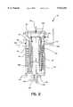
- FIG. 2is a schematic cross-sectional view showing a reformer according to an embodiment of the present invention
- FIG. 3is a schematic cross-sectional view showing a reformer according to another embodiment of the present invention.
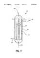
- FIG. 4is a schematic cross-sectional view showing a desulfurization reactor according to the present invention.
- the natural gas-using hydrogen generator of the present inventioncomprises a reformer 100, a desulfurization reactor 200, a heat exchanger 300, a P.S.A. 14, pipe lines 23, 25 and 26, and a pair of valve means 301 and 302.
- a water-supply tank 1is connected through a heat exchanger 4 to a water inlet 105a of the reformer 100 by a pipe line 3.
- the water stored in the water-supply tank 1is driven by a pump 2 and supplied to the reformer 100 via the pipe line 3.
- Hot product gasis generated in the reformer 100, exhausted out of its product gas outlet 101c and transferred through the heat exchanger 300 to the inlet of a CO conversion reactor 6 via a fourth pipe line 5.
- the outlet of the CO conversion reactor 6is connected through a heat exchanger 8 to a separator 9 via a pipe line 7.
- the product gas from the CO conversion reactor 6is cooled by the cooling water supplied via a pipe line 10 and thus, the product gas with ordinary temperatures is transferred to the separator 9.
- the product gasis separated from accompanying water which is, then, drained out. Almost all of the product gas is supplied via a pipe line 13 to a P.S.A. apparatus 14 in which the crude hydrogen is purified to a degree of high purity.
- a trace of the product gasis passed into a compressor 12 via a pipe line 11.
- the P.S.A. apparatus 14is filled with molecular sieves which serve to adsorb CO, CO 2 , CH 4 , H 2 O and the like other than H 2 for removal. While three atmosphere pressure operation and vacuum reproduction are alternatively carried out according to these adsorbent beds, highly pure hydrogen is produced. Off gas, which is generated upon the vacuum reproduction, is progressed along a pipe line 15 and stored in a tank with the aid of a vacuum pump 16. This can be a fuel source for the reformer 100. On the other hand, the highly pure hydrogen is highly pressured by a compressor 18 and led to a product gas tank 19 along a pipe line 17.
- Natural gasis pressurized by a compressor 12 and proceeds, along a pipe line 20, to a natural gas storage tank 21 which is connected to the desulfurization reactor 200 by a pipe line 22.
- Air which enters the reformer 100is preheated by a heater 24 and directed to an air inlet 101d of the reformer 100.
- a natural gas fuel pipe 108is divided from the pipe line 22 and connected to the air inlet 101d so that air-mixed fuel is provided to the reformer 100.
- a first valve means 302is provided in order to control the air which is fed to the heater 24.
- the second pipe line 23branches at a desired position between the first valve means 302 and the heater 24.
- Branched third pipe linedenoted by reference numeral "25” is directly led to the heat exchanger 300 and then, returns to a desired position of the second pipe line 23, but at a different position.
- the second valve means 301is provided between a returning point of the second pipe line 23 and the heat exchanger 300, to control the flow rate of the air which is to exchange heat with the hot product gas guided from the reformer 100 by the pipe line 5.
- Hot combustion heatoccurs at the reformer 100 and is transferred to the desulfurization reactor 200 via the first pipe line 26, serving to preheat the desulfurization reactor 200.
- the first pipe line 26 whose one end attaches to the desulfurization reactor 200is extended to a combustion gas outlet 101b of the reformer 100. During this extension, the pipe line 3 passes through the heat exchanger 4 at which the water introduced along the pipe line 3 is preheated by the hot combustion heat.
- the fuel which is deprived of sulfur by the desulfurization reactor 200is fed to the reformer 100 via a pipe line 27. That is, the pipe line 27 runs from the outlet of the desulfurization reactor 200 to the natural gas feed inlet 101a of the reformer 100.
- a reformer 100is provided largely with a casing 101, a reforming tube 102, a separator plate 103 for the reforming tube 102, a combustion compartment 104 and a coil 105 for producing steam.
- the casing 101is hollow with a desired diameter and a desired length. It is heat shielded by an insulation material 101f, having a natural gas feed inlet 101a, a combustion gas outlet 101b, a product gas outlet 101c and an air inlet 101d at its upper surface, side surface and lower surface.
- the natural gas feed inlet 101ais directly connected to the hollow cavity of the casing 101 at the center of its top surface, upwardly extending.
- the combustion gas outlet 101b and the product gas outlet 101ceach are directly connected to the inside hollow at a desired position of the circumference of the casing 101, outwardly extending.
- the air inlet 101dis located at the center of the bottom surface, downwardly extending.
- the reforming tube 102In the hollow of the casing 101, the reforming tube 102, the separator plate 103 for the reforming tube 102, the combustion compartment 104, and the coil 105 for producing steam are fixedly mounted.
- the combustion compartment 104is a kind of cylinder with a desired diameter and a desired length and its lower surface adheres closely to the bottom of the hollow of the casing 101. Being directly connected to the air inlet 101d of the casing 101, the combustion compartment 104 has combustion catalyst systems 106 and 107 at its upper and lower parts.
- the combustion catalyst systemseach are of cylindrical structure and their catalytically active component is prepared from palladium and precious metals.
- a natural gas fuel pipe 108which is divided into a fuel injection pipe 109 at a desired position.
- the fuel injection pipe 109is fixed in such a way that it vertically penetrates through the bottom surface of the casing 101 into the central inside of the combustion compartment 104 at a desired span. While a plurality of injection holes 109a are formed on the outer circumference of an upper part of the fuel injection pipe 109, a valve 109b is provided at the lower end thereof.
- the reforming tube 102As for the reforming tube 102, a cross sectional view of an inverted hat is given. On a downward protrusion of the reforming tube 102, an upwardly bent concave 102a with a desired diameter and a desired length is provided, leaving a certain space from the combustion compartment 104.
- the upper end of the reforming tube 102is sealingly bonded along the upper inner circumference of the inside hollow of the casing 101, compartmenting the inner hollow of the casing 101 while the lower surface thereof is a desired space apart from the bottom of the inside hollow of the casing 101, defining a flow passage of the combustion gas.
- the separator plate 103 for the reforming tube 102has a cylindrical shape with a desired diameter and a desired length, on the whole. Its upper part is a funnel form that is outwardly bent at a certain angle and sealingly bonded along the upper inner circumference of the hollow of the casing 101. On the other hand, the lower surface is a desired space apart from the bottom of the reforming tube 102, compartmenting the interior of the reforming tube 102.
- the coil 105 for producing steamis a tube with a desired diameter and closely winds around the outer circumference surface of the reforming tube 102 in a spiral form. Its opposite ends externally extend through respective desired positions of the casing 101, one end serving as a water inlet 105a and the other serving as a steam outlet 105b. The latter is connected to the natural gas feed inlet 101a of the casing 101.
- a reformer catalyst 110 having a type of nickelis filled in the inner space between the reforming tube 102 and the separator plate 103 for the reforming tube 102.
- FIG. 3there is a reformer structure according to a second embodiment of the present invention.
- This reformeris largely similar to that of the first embodiment except for a combustion catalyst system 150 provided in a combustion compartment 104 and the absence of the fuel injection pipe 109 of FIG. 2 according to the characteristics of the combustion catalyst system 150.
- the combustion catalyst system 150consists of a plurality of sheets of circular wire mesh coated with palladium 150a and a cylindrical metal construct coated with palladium 150b and is fixedly set beneath the combustion compartment 104.
- a primary combustionoccurs, burning 40% of the mix. The remainder is completely burned while passing a plurality of sheets of circular wire mesh 150a.
- This desulfurization reactor 200is comprised largely of a casing 201 and a plurality of finned tubes 202.
- a tube configuration which has a cavity thereinis given to the casing 201 and its opposite top and bottom surfaces are dome-shaped.
- a natural gas inlet 201ais located at the top surface, penetrating into the cavity while a natural gas outlet 201b is at the bottom surface, penetrating into the cavity.
- a combustion gas outlet 201c and a combustion gas inlet 201dare each integrated into the casing 201 at a desired position of its circumference.
- a plurality of the finned tubes 202are fixedly settled in a vertical direction.
- an absorption catalyst layer 204 of hydrogen sulfide (H 2 S)is filled in the lower part of the finned tube 202.
- the natural gas inlet 201ais extended to the natural gas storage tank 21 via the pipe line 22 for the provision of natural gas to the desulfurization reactor 200.
- the resulting desulfurized natural gasflows off through a natural gas outlet 201b and is led to the natural gas feed inlet 101a via the pipe line 27 to enter the reformer 100.
- the combustion gas inlet 201dis directly connected to the combustion gas outlet 101b of the reformer 100 via the first pipe line 26.
- the combustion gas introduced into the cavityis drained off through the combustion gas outlet 201c.
- the natural gas-using hydrogen generator in accordance with the present inventioncomprises the first valve means 302 to control the flow rate of air provided the heater 24 on the air-providing second pipe line 23, the third pipe line 25 whose both ends are connected to the second pipe line 23, the second valve means 301 existing at a desired position of the third pipe line 25 for air control, the heat exchanger 300 which exchanges the heat between the third pipe line 25 and the forth pipe line 5 to cool the hot product gas from the reformer 100, and the first pipe line 26 which connects the combustion gas outlet 101b of the reformer 100 with the combustion gas inlet 201d of the desulfurization reactor 200, wherein said desulfurization reactor 200 is uniformly and directly preheated by the hot combustion gas produced from the reformer 100 without any additional boiler and electric heater system, whereby the total start-up time can be reduced, the time which it takes to be ready for initial operating can be reduced and a significant improvement can be made to the optimal temperature condition and the heat efficiency.
- the natural gas-using hydrogen generatoris characterized in that a reformer 100 and a desulfurization reactor 200 are interconnected with each other, so that the hot combustion gas produced upon operating the reformer 100 is provided to and directly preheats the desulfurization reactor 200, thereby reducing the total start-up time of said hydrogen generator.
- the first valve means 302to control the flow rate of air provided to the heater 24 on the air-providing second pipe line 23, the third pipe line 25, the second valve means 301 provided on the third pipe line 25 for controlling air flow, and the heat exchanger 300 in which heat exchanges between the third pipe line 25 and the fourth pipe line 5 to cool the product gas from the reformer 100, thereby significantly reducing the time that it takes the hydrogen generator to be ready for initial operating and improving the optimal temperature condition and the heat efficiency thereof.
- such a structure according to the present inventionenables the hydrogen generator to be well operated without any additional preheater for the desulfurization reactor and thus, to be manufactured smaller. Also, there is an economic advantage that installation and maintenance costs are low.
Landscapes
- Chemical & Material Sciences (AREA)
- Organic Chemistry (AREA)
- Chemical Kinetics & Catalysis (AREA)
- Engineering & Computer Science (AREA)
- Inorganic Chemistry (AREA)
- Health & Medical Sciences (AREA)
- Combustion & Propulsion (AREA)
- Biomedical Technology (AREA)
- General Health & Medical Sciences (AREA)
- Environmental & Geological Engineering (AREA)
- Analytical Chemistry (AREA)
- General Chemical & Material Sciences (AREA)
- Oil, Petroleum & Natural Gas (AREA)
- Physics & Mathematics (AREA)
- Fluid Mechanics (AREA)
- Hydrogen, Water And Hydrids (AREA)
Abstract
Description
1. Field of the Invention
The present invention relates, in general, to a hydrogen generator and, more particularly, to a natural gas-using hydrogen generator, which can produce high purity hydrogen from natural gas itself by reacting natural gas with water without the aid of additional equipment.
2. Description of the Prior Art
Production of hydrogen from natural gas is generally accomplished by three techniques: steam reforming; partial oxidation; and autothermal reforming.
Of them, the partial oxidation and the autothermal reforming techniques are economically unfavorable owing to the limit that additional oxygen is to be fed. Thus, the steam reforming technique has been widely employed. Here, the following description will be given based on steam reforming technique.
A typical steam reforming process consists mainly of a reforming step where hydrocarbons are reacted with heated steam to produce various reformed gases and a refining and recovering step where hydrogen gas is recovered from the reformed gases. Examples of the hydrocarbons include natural gas, propane, butane, naphtha, etc.
The following is a detailed description for a conventional steam reforming technique using natural gas as a raw material. Natural gas includes methane as its major component, which reacts with steam as follows:
CH.sub.4 +H.sub.2 O=3H.sub.2 +CO H=206 kJ/gmol (I)
The production of hydrogen and carbon monoxide from natural gas and steam according to Reaction I is usually carried out in the presence of a modifying catalyst (e.g. Ni). As shown, this reaction is strongly endothermic, so that an external heat should be supplied. For this reaction, a temperature of 500 to 1,000° C. should be maintained under a pressure of 1 to 20 atm. To prevent the reverse reaction of methane production and the production of coke on a catalyst, excess steam is to be fed into the reaction system. In case of natural gas, the mole ratio of steam to hydrocarbon should be maintained in a range of about 3 to 3.5.
In a large hydrogen plant, a reformer comprises a large furnace in which a plurality of catalyst tubes are operated at a temperature of 900 to 1,000° C. In spite of such high temperatures, its heat efficiency is as low as 60 to 70%.
In addition to Reaction I, the conversion reaction of carbon monoxide into hydrogen occurs as represented by the following Reaction II:
CO+H.sub.2 O=H.sub.2 +CO.sub.2 H=-41 kJ/gmol (II)
Reaction II, so-called water/gas shift reaction, is exothermic so that, as the reaction temperature is lower, the conversion of carbon monoxide is higher. Accordingly, the reaction is heated only up to a temperature of 180 to 300° C. while maintaining the pressure from 1 to 20 atm. Carbon monoxide is high in concentration at the outlet of the reformer, which is operated at a high temperature. A heat exchanger is provided at the tail of the reformer with the aim of lowering the temperature of the gas and the gas is allowed to pass through a conversion reactor (in which Cu type catalyst is filled) with the aim of lowering the concentration of carbon monoxide and increasing the yield of hydrogen.
Natural gas contains a trace of sulfur compounds which serve to alert the leakage of natural gas by their characteristic odor. During the reaction, these sulfur compounds are coated on the reformer catalysts, which then become incapacitated. Thus, it should be pre-treated to be desulfurized. For this, a desulfurization reactor filled with hydrodesulfurization catalysts and absorption catalysts of H2 S (hydrogen sulfide) is set at the head of the reformer and maintains a temperature of 150 to 350° C.
Largely, the start up time of the total system depends upon the period which it takes the desulfurization reactor to be ready for operation. Conventionally, the desulfurization reactor is warmed-up by an electric heater or indirectly preheated by exchanging the heat which occurs when nitrogen flows. In addition, an additional gas boiler is set to convert water material into steam.
This electric heater which is to warm up the desulfurization reactor of the conventional natural gas-using hydrogen generator causes a high temperature locally around it, deteriorating the desulfurization catalyst. In addition, the electric heater is economically unfavorable because the maintenance cost is high owing to its consuming a great deal of power. Because the electric heater is difficult to set up in the desulfurization reactor, its assembly is significantly low in productivity.
Further, the additional gas boiler is required to generate steam, which results in an excess of the hydrogen generator. Moreover, the product gas containing hydrogen from the reformer does not reach the conversion reactor without heat recovery and reuse, so that the total heat efficiency of the hydrogen generator is remarkably lowered.
Therefore, it is an objective of the present invention to overcome the above problems encountered in prior arts and to provide a compact natural gas-using hydrogen generator which is remarkably reduced in the number of equipment parts so that the space necessary to set it up can be reduced.
It is another objective of the present invention to provide a natural gas-using hydrogen generator which is low in manufacture cost and establishment cost.
It is a further objective of the present invention to provide a natural gas-using hydrogen generator which comprises a desulfurization reactor that needs no electric heater, so that the hydrogen generator is significantly improved in assembly productivity, necessary start-up time, and heat efficiency.
In accordance with the present invention, the above objectives can be accomplished by a provision of a natural gas-using hydrogen generator comprising a desulfurization reactor, a reformer, a CO conversion reactor and a P.S.A. (Pressure Swing Unit Absoption), wherein said natural gas-using hydrogen generator further comprises a first pipe line for connecting said reformer with the desulfurization reactor to provide hot combustion gas from the reformer to the desulfurization reactor and to preheat the desulfurization reactor; a first valve means for controlling air flow being fed to the reformer, which is provided on a second pipe line for feeding air into the reformer; a heat exchanger for exchanging heat between a third pipe line, whose both ends are connected to the second pipe line with the first valve means being therebetween, and a fourth pipe line which leads a hot product gas from the reformer to the CO conversion reactor, to cool the product gas; and a second valve means for controlling air flow being fed to the third pipe line, which is provided on a desired position of the third pipe line.
Other objectives and aspects of the invention will become apparent from the following description of embodiments with reference to the accompanying drawings in which:
FIG. 1 is a process flow of a hydrogen generator according to the present invention;
FIG. 2 is a schematic cross-sectional view showing a reformer according to an embodiment of the present invention;
FIG. 3 is a schematic cross-sectional view showing a reformer according to another embodiment of the present invention; and
FIG. 4 is a schematic cross-sectional view showing a desulfurization reactor according to the present invention.
The application of the preferred embodiment of the present invention is best understood with reference to the accompanying drawings, wherein same reference numerals are used for same and corresponding parts, respectively.
Referring to FIG. 1, there is a process flow in the natural gas-using hydrogen generator according to the present invention. As shown in FIG. 1, the natural gas-using hydrogen generator of the present invention comprises areformer 100, adesulfurization reactor 200, aheat exchanger 300, a P.S.A. 14,pipe lines
According to the process flow, a water-supply tank 1 is connected through aheat exchanger 4 to awater inlet 105a of thereformer 100 by apipe line 3. The water stored in the water-supply tank 1 is driven by apump 2 and supplied to thereformer 100 via thepipe line 3.
Hot product gas is generated in thereformer 100, exhausted out of itsproduct gas outlet 101c and transferred through theheat exchanger 300 to the inlet of aCO conversion reactor 6 via afourth pipe line 5. The outlet of theCO conversion reactor 6 is connected through aheat exchanger 8 to a separator 9 via apipe line 7.
In theheat exchanger 8, the product gas from theCO conversion reactor 6 is cooled by the cooling water supplied via apipe line 10 and thus, the product gas with ordinary temperatures is transferred to the separator 9.
In the separator 9, the product gas is separated from accompanying water which is, then, drained out. Almost all of the product gas is supplied via apipe line 13 to a P.S.A.apparatus 14 in which the crude hydrogen is purified to a degree of high purity. For providing hydrogen for a desulfurization reaction, a trace of the product gas is passed into acompressor 12 via apipe line 11.
The P.S.A.apparatus 14 is filled with molecular sieves which serve to adsorb CO, CO2, CH4, H2 O and the like other than H2 for removal. While three atmosphere pressure operation and vacuum reproduction are alternatively carried out according to these adsorbent beds, highly pure hydrogen is produced. Off gas, which is generated upon the vacuum reproduction, is progressed along apipe line 15 and stored in a tank with the aid of avacuum pump 16. This can be a fuel source for thereformer 100. On the other hand, the highly pure hydrogen is highly pressured by acompressor 18 and led to aproduct gas tank 19 along apipe line 17.
Natural gas is pressurized by acompressor 12 and proceeds, along apipe line 20, to a naturalgas storage tank 21 which is connected to thedesulfurization reactor 200 by apipe line 22.
Air which enters thereformer 100 is preheated by aheater 24 and directed to anair inlet 101d of thereformer 100. A naturalgas fuel pipe 108 is divided from thepipe line 22 and connected to theair inlet 101d so that air-mixed fuel is provided to thereformer 100.
At a desired position of asecond pipe line 23, a first valve means 302 is provided in order to control the air which is fed to theheater 24. Thesecond pipe line 23 branches at a desired position between the first valve means 302 and theheater 24. Branched third pipe line, denoted by reference numeral "25", is directly led to theheat exchanger 300 and then, returns to a desired position of thesecond pipe line 23, but at a different position. The second valve means 301 is provided between a returning point of thesecond pipe line 23 and theheat exchanger 300, to control the flow rate of the air which is to exchange heat with the hot product gas guided from thereformer 100 by thepipe line 5.
Hot combustion heat occurs at thereformer 100 and is transferred to thedesulfurization reactor 200 via thefirst pipe line 26, serving to preheat thedesulfurization reactor 200.
Thefirst pipe line 26 whose one end attaches to thedesulfurization reactor 200 is extended to acombustion gas outlet 101b of thereformer 100. During this extension, thepipe line 3 passes through theheat exchanger 4 at which the water introduced along thepipe line 3 is preheated by the hot combustion heat.
The fuel which is deprived of sulfur by thedesulfurization reactor 200 is fed to thereformer 100 via apipe line 27. That is, thepipe line 27 runs from the outlet of thedesulfurization reactor 200 to the naturalgas feed inlet 101a of thereformer 100.
Referring to FIG. 2, there is a reformer structure according to a first embodiment of the present invention. As seen, areformer 100 is provided largely with acasing 101, a reformingtube 102, aseparator plate 103 for the reformingtube 102, acombustion compartment 104 and acoil 105 for producing steam.
Thecasing 101 is hollow with a desired diameter and a desired length. It is heat shielded by aninsulation material 101f, having a naturalgas feed inlet 101a, acombustion gas outlet 101b, aproduct gas outlet 101c and anair inlet 101d at its upper surface, side surface and lower surface. In detail, the naturalgas feed inlet 101a is directly connected to the hollow cavity of thecasing 101 at the center of its top surface, upwardly extending. Thecombustion gas outlet 101b and theproduct gas outlet 101c each are directly connected to the inside hollow at a desired position of the circumference of thecasing 101, outwardly extending. Likewise, theair inlet 101d is located at the center of the bottom surface, downwardly extending.
In the hollow of thecasing 101, the reformingtube 102, theseparator plate 103 for the reformingtube 102, thecombustion compartment 104, and thecoil 105 for producing steam are fixedly mounted.
Thecombustion compartment 104 is a kind of cylinder with a desired diameter and a desired length and its lower surface adheres closely to the bottom of the hollow of thecasing 101. Being directly connected to theair inlet 101d of thecasing 101, thecombustion compartment 104 hascombustion catalyst systems
At a desired position of theair inlet 101d of thecasing 101 is provided a naturalgas fuel pipe 108 which is divided into afuel injection pipe 109 at a desired position. Thefuel injection pipe 109 is fixed in such a way that it vertically penetrates through the bottom surface of thecasing 101 into the central inside of thecombustion compartment 104 at a desired span. While a plurality ofinjection holes 109a are formed on the outer circumference of an upper part of thefuel injection pipe 109, avalve 109b is provided at the lower end thereof.
As for the reformingtube 102, a cross sectional view of an inverted hat is given. On a downward protrusion of the reformingtube 102, an upwardly bent concave 102a with a desired diameter and a desired length is provided, leaving a certain space from thecombustion compartment 104. The upper end of the reformingtube 102 is sealingly bonded along the upper inner circumference of the inside hollow of thecasing 101, compartmenting the inner hollow of thecasing 101 while the lower surface thereof is a desired space apart from the bottom of the inside hollow of thecasing 101, defining a flow passage of the combustion gas.
Theseparator plate 103 for the reformingtube 102 has a cylindrical shape with a desired diameter and a desired length, on the whole. Its upper part is a funnel form that is outwardly bent at a certain angle and sealingly bonded along the upper inner circumference of the hollow of thecasing 101. On the other hand, the lower surface is a desired space apart from the bottom of the reformingtube 102, compartmenting the interior of the reformingtube 102.
Thecoil 105 for producing steam is a tube with a desired diameter and closely winds around the outer circumference surface of the reformingtube 102 in a spiral form. Its opposite ends externally extend through respective desired positions of thecasing 101, one end serving as awater inlet 105a and the other serving as asteam outlet 105b. The latter is connected to the naturalgas feed inlet 101a of thecasing 101.
In the inner space between the reformingtube 102 and theseparator plate 103 for the reformingtube 102, areformer catalyst 110 having a type of nickel is filled.
Now, with reference to FIG. 3, there is a reformer structure according to a second embodiment of the present invention. This reformer is largely similar to that of the first embodiment except for acombustion catalyst system 150 provided in acombustion compartment 104 and the absence of thefuel injection pipe 109 of FIG. 2 according to the characteristics of thecombustion catalyst system 150.
Thecombustion catalyst system 150 consists of a plurality of sheets of circular wire mesh coated with palladium 150a and a cylindrical metal construct coated withpalladium 150b and is fixedly set beneath thecombustion compartment 104. When a mix of fuel and air flows through the narrow spaces of thecylindrical metal construct 150b and thecombustion compartment 104, a primary combustion occurs, burning 40% of the mix. The remainder is completely burned while passing a plurality of sheets of circular wire mesh 150a.
Now, with reference to FIG. 4, there is a desulfurization reactor according to the present invention. Thisdesulfurization reactor 200 is comprised largely of acasing 201 and a plurality offinned tubes 202.
A tube configuration which has a cavity therein is given to thecasing 201 and its opposite top and bottom surfaces are dome-shaped. Anatural gas inlet 201a is located at the top surface, penetrating into the cavity while anatural gas outlet 201b is at the bottom surface, penetrating into the cavity. With direct connection to the cavity, acombustion gas outlet 201c and acombustion gas inlet 201d are each integrated into thecasing 201 at a desired position of its circumference. In the cavity of thecasing 201, a plurality of thefinned tubes 202, preferably at least 3 in number, are fixedly settled in a vertical direction.
Being overlaid by ahydrodesulfurization catalyst layer 203, anabsorption catalyst layer 204 of hydrogen sulfide (H2 S) is filled in the lower part of thefinned tube 202.
Thenatural gas inlet 201a is extended to the naturalgas storage tank 21 via thepipe line 22 for the provision of natural gas to thedesulfurization reactor 200.
The resulting desulfurized natural gas flows off through anatural gas outlet 201b and is led to the naturalgas feed inlet 101a via thepipe line 27 to enter thereformer 100.
Preheated by the hot combustion gas provided from thereformer 100, thecombustion gas inlet 201d is directly connected to thecombustion gas outlet 101b of thereformer 100 via thefirst pipe line 26. The combustion gas introduced into the cavity is drained off through thecombustion gas outlet 201c.
Accordingly, the natural gas-using hydrogen generator in accordance with the present invention comprises the first valve means 302 to control the flow rate of air provided theheater 24 on the air-providingsecond pipe line 23, thethird pipe line 25 whose both ends are connected to thesecond pipe line 23, the second valve means 301 existing at a desired position of thethird pipe line 25 for air control, theheat exchanger 300 which exchanges the heat between thethird pipe line 25 and theforth pipe line 5 to cool the hot product gas from thereformer 100, and thefirst pipe line 26 which connects thecombustion gas outlet 101b of thereformer 100 with thecombustion gas inlet 201d of thedesulfurization reactor 200, wherein saiddesulfurization reactor 200 is uniformly and directly preheated by the hot combustion gas produced from thereformer 100 without any additional boiler and electric heater system, whereby the total start-up time can be reduced, the time which it takes to be ready for initial operating can be reduced and a significant improvement can be made to the optimal temperature condition and the heat efficiency.
As described hereinbefore, the natural gas-using hydrogen generator is characterized in that areformer 100 and adesulfurization reactor 200 are interconnected with each other, so that the hot combustion gas produced upon operating thereformer 100 is provided to and directly preheats thedesulfurization reactor 200, thereby reducing the total start-up time of said hydrogen generator. In addition, it is further furnished with the first valve means 302 to control the flow rate of air provided to theheater 24 on the air-providingsecond pipe line 23, thethird pipe line 25, the second valve means 301 provided on thethird pipe line 25 for controlling air flow, and theheat exchanger 300 in which heat exchanges between thethird pipe line 25 and thefourth pipe line 5 to cool the product gas from thereformer 100, thereby significantly reducing the time that it takes the hydrogen generator to be ready for initial operating and improving the optimal temperature condition and the heat efficiency thereof. Moreover, such a structure according to the present invention enables the hydrogen generator to be well operated without any additional preheater for the desulfurization reactor and thus, to be manufactured smaller. Also, there is an economic advantage that installation and maintenance costs are low.
The present invention has been described in an illustrative manner, and it is to be understood the terminology used is intended to be in the nature of description rather than of limitation.
Many modifications and variations of the present invention are possible in light of the above teachings. Therefore, it is to be understood that within the scope of the appended claims, the invention may be practiced otherwise than as specifically described.
Claims (15)
1. A natural gas-using hydrogen generator comprising a desulfurization reactor, a reformer, a CO conversion reactor, a Pressure Swing Absorption Unit and:
a first pipe line for connecting said reformer with said desulfurization reactor to provide combustion gas from said reformer to said desulfurization reactor and to preheat said desulfurization reactor, the desulfurization reactor having a combustion gas inlet and the reformer having a combustion gas oulet;
a first valve means for controlling air flow being fed to said reformer, said first valve means provided on a second pipe line for feeding air into the reformer;
a heat exchanger for exchanging heat between a third pipe line, both ends of the third pipe line connected to said second pipe line with said first valve means being therebetween, and a fourth pipe line which conveys a product gas form said reformer to said CO conversion reactor, to cool said product gas; and
a second valve means for controlling air flow being fed to said third pipe line, the second valve means provided on a position of said third pipe line.
2. The natural gas-using hydrogen generator in accordance with claim 1, wherein said reformer comprises:
a cylindrical casing having a hollow cavity;
a combustion compartment, having an upper part and a lower part, mounted in the longitudinal direction of the hollow cavity;
a reforming tube vertically fixed in the interior of said hollow cavity, surrounding said combustion compartment at a distance;
a separator plate for separating the interior of said reforming tube, which is vertically fixed at a distance apart from the bottom of said reforming tube;
a coil for producing steam, which winds around the circumference of the reforming tube, and the coil having opposing ends extending through the casing into the exterior of the casing;
a natural gas feed inlet connected directly to said hollow cavity at the center of the top surface of said casing, with its end extending to one end of said coil;
a reformer catalyst system filling the space between the inner side of said reforming tube and the inner side of said plate;
a combustion catalyst system fixed at positions of the upper and lower part within the combustion compartment;
an air inlet connected directly to said hollow cavity at the center of the bottom surface of said casing, with one end downwardly extending to a heater;
a natural gas fuel pipe branching off from a position of said air inlet;
a combustion gas outlet directly connecting the space between the outer side of said reforming tube and the inner side of said casing; and
a product gas outlet connected directly to an inner space which is defined in said casing by said reforming tube.
3. The natural gas-using hydrogen generator in accordance with claim 1, wherein said desulfurization reactor comprises:
a casing having a hollow cavity therein, a natural gas inlet and a natural gas outlet which are respectively connected to said hollow cavity at a top surface and a bottom surface thereof, and a combustion gas inlet and a combustion gas outlet which are each connected to said hollow cavity at a position on the circumference thereof; and
a plurality of finned tubes fixedly settled in said hollow cavity of said casing, in which a hydrodesulfurization catalyst layer and an adsorption catalyst layer of hydrogen sulfide are filled in descending order.
4. The natural gas-using hydrogen generator in accordance with claim 1, wherein said first pipe line connects said desulfurization reactor with said reformer so that one end of said first pipe line is attached to said combustion gas inlet of said desulfurization reactor and the other end of said first pipe line is attached to said combustion gas outlet of said reformer.
5. The natural gas-using hydrogen generator in accordance with claim 2, wherein said first pipe line connects said desulfurization reactor with said reformer so that one end of said first pipe line is attached to said combustion gas inlet of said desulfurization reactor and the other end of said first pipe line is attached to said combustion gas outlet of said reformer.
6. The natural gas-using hydrogen generator in accordance with claim 3, wherein said first pipe line connects said desulfurization reactor with said reformer so that one end of said first pipe line is attached to said combustion gas inlet of said desulfurization reactor and the other end of said first pipe line is attached to said combustion gas outlet of said reformer.
7. The natural gas-using hydrogen generator in accordance with claim 2, wherein said combustion catalyst system comprises two catalyst units which each have a cylindrical shape and are provided on the upper part and the lower part of said combustion compartment, the catalyst units containing palladium.
8. The natural gas-using hydrogen generator in accordance with claim 2, wherein said combustion catalyst system comprises two catalyst units, one unit having a cylindrical shape and coated with a palladium type metal and fixedly provided at the lower part of said combustion compartment and the other catalyst unit being in the form of sheets of circular wire meshes which are coated with palladium and fixedly provided at the upper part of the combustion compartment.
9. The natural gas-using hydrogen generator in accordance with claim 2, wherein said coil for producing steam is a tube with opposite ends which externally extend through respective positions of said casing, one end serving as a water inlet and the other end serving as a steam outlet.
10. The natural gas-using hydrogen generator in accordance with claim 9, wherein said steam outlet is connected to said natural gas feed inlet.
11. The natural gas-using hydrogen generator in accordance with claim 3, wherein said finned tubes are at least 3 in number.
12. The natural gas-using hydrogen generator in accordance with claim 2, wherein said natural gas fuel pipe branches off at a position into a fuel injection pipe which vertically penetrates through the bottom surface of said casing into the combustion compartment, the fuel injection pipe serving to inject fuel to said combustion catalyst system and having a plurality of injection holes formed on the circumference of an upper part thereof.
13. The natural gas-using hydrogen generator in accordance with claim 7, wherein said natural gas fuel pipe branches off at a position into a fuel injection pipe which vertically penetrates through the bottom surface of said casing into the combustion compartment, the fuel injection pipe serving to inject fuel to said combustion catalyst system and having a plurality of injection holes formed on the circumference of an upper part thereof.
14. The natural gas-using hydrogen generator in accordance with claim 12, wherein said fuel injection pipe is provided with a valve means for monitoring fuel supply and controlling fuel flow.
15. The natural gas-using hydrogen generator in accordance with claim 13, wherein said fuel injection pipe is provided with a valve means for monitoring fuel supply and controlling fuel flow.
Applications Claiming Priority (2)
| Application Number | Priority Date | Filing Date | Title |
|---|---|---|---|
| KR96-70402 | 1996-12-23 | ||
| KR1019960070402AKR100209989B1 (en) | 1996-12-23 | 1996-12-23 | Natural Gas Hydrogen Generator |
Publications (1)
| Publication Number | Publication Date |
|---|---|
| US5932181Atrue US5932181A (en) | 1999-08-03 |
Family
ID=19490328
Family Applications (1)
| Application Number | Title | Priority Date | Filing Date |
|---|---|---|---|
| US08/988,364Expired - Fee RelatedUS5932181A (en) | 1996-12-23 | 1997-12-10 | Natural gas-using hydrogen generator |
Country Status (3)
| Country | Link |
|---|---|
| US (1) | US5932181A (en) |
| JP (1) | JP4090097B2 (en) |
| KR (1) | KR100209989B1 (en) |
Cited By (60)
| Publication number | Priority date | Publication date | Assignee | Title |
|---|---|---|---|---|
| US6221117B1 (en) | 1996-10-30 | 2001-04-24 | Idatech, Llc | Hydrogen producing fuel processing system |
| US6375906B1 (en) | 1999-08-12 | 2002-04-23 | Idatech, Llc | Steam reforming method and apparatus incorporating a hydrocarbon feedstock |
| US6376113B1 (en) | 1998-11-12 | 2002-04-23 | Idatech, Llc | Integrated fuel cell system |
| US20020058170A1 (en)* | 2000-10-25 | 2002-05-16 | Wolfgang Luck | Apparatus and method for supplying fuel to a gas-generating system |
| US20020083645A1 (en)* | 2000-11-13 | 2002-07-04 | Edlund David J. | Fuel processing system and improved feedstock therefor |
| US20020108306A1 (en)* | 2001-02-12 | 2002-08-15 | Grieve Malcolm James | Reformer controls |
| WO2002062463A1 (en)* | 2000-10-27 | 2002-08-15 | Harvest Energy Technology, Inc. | Fuel processor apparatus and control system |
| US6451464B1 (en) | 2000-01-03 | 2002-09-17 | Idatech, Llc | System and method for early detection of contaminants in a fuel processing system |
| US6465118B1 (en) | 2000-01-03 | 2002-10-15 | Idatech, Llc | System and method for recovering thermal energy from a fuel processing system |
| US6495277B1 (en) | 1999-07-27 | 2002-12-17 | Idatech, Llc | Fuel cell system controller |
| US20020192136A1 (en)* | 2001-06-15 | 2002-12-19 | Omg Ag & Co. Kg | Process for preparing a low-sulfur reformate gas for use in a fuel cell system |
| US20030051405A1 (en)* | 2001-04-26 | 2003-03-20 | Robert Childress | Compact fuel processor for producing a hydrogen rich gas |
| US6537352B2 (en) | 1996-10-30 | 2003-03-25 | Idatech, Llc | Hydrogen purification membranes, components and fuel processing systems containing the same |
| US20030078167A1 (en)* | 2001-04-21 | 2003-04-24 | Frank Ziemer | Herbicides comprising benzoylcyclohexanediones and safeners |
| US6562111B2 (en) | 2001-09-27 | 2003-05-13 | Idatech, Llc | Hydrogen purification devices, components and fuel processing systems containing the same |
| US6569227B2 (en) | 2001-09-27 | 2003-05-27 | Idatech, Llc | Hydrogen purification devices, components and fuel processing systems containing the same |
| US20030113601A1 (en)* | 2000-07-26 | 2003-06-19 | Edlund David J. | Fuel cell system controller |
| US6607703B1 (en)* | 1999-05-24 | 2003-08-19 | Matsushita Electric Industrial Co., Ltd. | Hydrogen generator |
| US20030167690A1 (en)* | 2002-03-05 | 2003-09-11 | Edlund David J. | Feedstock delivery system and fuel processing systems containing the same |
| US6620537B2 (en)* | 2001-02-15 | 2003-09-16 | Ralph C. Struthers | Hydrocarbon fueled hydrogen fuel generator system and apparatus in combination with hydrogen fuel cells |
| US20030215374A1 (en)* | 2002-05-14 | 2003-11-20 | Wheeldon Ian R. | Compact methanol steam reformer with integrated hydrogen separation |
| US6653005B1 (en) | 2000-05-10 | 2003-11-25 | University Of Central Florida | Portable hydrogen generator-fuel cell apparatus |
| US6783741B2 (en) | 1996-10-30 | 2004-08-31 | Idatech, Llc | Fuel processing system |
| US20040197616A1 (en)* | 2003-04-01 | 2004-10-07 | Edlund David J. | Oxidant-enriched fuel cell system |
| WO2005073126A1 (en) | 2004-01-30 | 2005-08-11 | Idemitsu Kosan Co., Ltd. | Reformer |
| US20050188616A1 (en)* | 2004-02-27 | 2005-09-01 | Bizjak Travis A. | Fuel processing treatment system and fuel processing systems containing the same |
| US20050266284A1 (en)* | 2004-05-28 | 2005-12-01 | Mesa Scharf | Consumption-based fuel cell monitoring and control |
| US20060024540A1 (en)* | 2004-07-29 | 2006-02-02 | Laven Arne | Shared variable-based fuel cell system control |
| US20060045828A1 (en)* | 2004-09-01 | 2006-03-02 | Aaron Timothy M | Catalytic reactor |
| US20060157484A1 (en)* | 2005-01-18 | 2006-07-20 | Menashe Rogotner | Carton, blank therefor and packing arrangement thereof |
| US7135048B1 (en) | 1999-08-12 | 2006-11-14 | Idatech, Llc | Volatile feedstock delivery system and fuel processing system incorporating the same |
| WO2007020427A1 (en)* | 2005-08-15 | 2007-02-22 | Voller Energy Limited | Hydrogen generator |
| US7195663B2 (en) | 1996-10-30 | 2007-03-27 | Idatech, Llc | Hydrogen purification membranes, components and fuel processing systems containing the same |
| US20070113475A1 (en)* | 2001-11-01 | 2007-05-24 | Edlund David J | Fuel processing systems, fuel cell systems, and improved feedstocks therefor |
| US20070243444A1 (en)* | 2004-02-13 | 2007-10-18 | Alberta Research Council, Inc. | Heating Solid Oxide for Fuel Cell Stack |
| US7341609B2 (en) | 2002-10-03 | 2008-03-11 | Genesis Fueltech, Inc. | Reforming and hydrogen purification system |
| US7470293B2 (en) | 2004-10-29 | 2008-12-30 | Idatech, Llc | Feedstock delivery systems, fuel processing systems, and hydrogen generation assemblies including the same |
| US20090188449A1 (en)* | 2008-01-24 | 2009-07-30 | Hydrogen Technology Applications, Inc. | Method to enhance and improve solid carbonaceous fuel combustion systems using a hydrogen-rich gas |
| US7601302B2 (en) | 2005-09-16 | 2009-10-13 | Idatech, Llc | Self-regulating feedstock delivery systems and hydrogen-generating fuel processing assemblies and fuel cell systems incorporating the same |
| US7628963B2 (en) | 2004-12-07 | 2009-12-08 | Sk Energy Co., Ltd. | Small cylindrical reformer |
| US7691271B1 (en) | 2007-05-30 | 2010-04-06 | University Of Central Florida Research Foundation, Inc. | Filamentous carbon particles for cleaning oil spills and method of production |
| US7887958B2 (en) | 2006-05-15 | 2011-02-15 | Idatech, Llc | Hydrogen-producing fuel cell systems with load-responsive feedstock delivery systems |
| US7939051B2 (en) | 2006-05-23 | 2011-05-10 | Idatech, Llc | Hydrogen-producing fuel processing assemblies, heating assemblies, and methods of operating the same |
| US7972420B2 (en) | 2006-05-22 | 2011-07-05 | Idatech, Llc | Hydrogen-processing assemblies and hydrogen-producing systems and fuel cell systems including the same |
| US8021446B2 (en) | 2005-09-16 | 2011-09-20 | Idatech, Llc | Self-regulating feedstock delivery systems and hydrogen-generating fuel processing assemblies and fuel cell systems incorporating the same |
| EP2212242A4 (en)* | 2007-11-01 | 2012-08-29 | Sk Innovation Co Ltd | HYDROGEN GENERATOR WITH EASY ACCESS, STABLE OPERATION AND HIGH EFFICIENCY |
| US8262752B2 (en) | 2007-12-17 | 2012-09-11 | Idatech, Llc | Systems and methods for reliable feedstock delivery at variable delivery rates |
| WO2013021140A1 (en)* | 2011-08-11 | 2013-02-14 | L'air Liquide,Societe Anonyme Pour L'etude Et L'exploitation Des Procedes Georges Claude | Method for producing hydrogen from biogas |
| CN103191626A (en)* | 2013-04-01 | 2013-07-10 | 国家电网公司 | Safe desulfurization test point measuring device |
| US20150030943A1 (en)* | 2013-01-24 | 2015-01-29 | Panasonic Corporation | Fuel cell system |
| EP2977348A4 (en)* | 2013-03-19 | 2016-03-30 | Panasonic Ip Man Co Ltd | HYDROGEN GENERATOR APPARATUS, FUEL CELL SYSTEM COMPRISING SAME, AND METHOD OF OPERATING HYDROGEN GENERATING APPARATUS AND FUEL CELL SYSTEM |
| CN108455527A (en)* | 2018-02-23 | 2018-08-28 | 王杰 | A kind of preparation facilities of novel super-high purity hydrogen |
| RU2679241C1 (en)* | 2018-03-12 | 2019-02-06 | Андрей Владиславович Курочкин | Hydrogen recovery plant |
| US10476093B2 (en) | 2016-04-15 | 2019-11-12 | Chung-Hsin Electric & Machinery Mfg. Corp. | Membrane modules for hydrogen separation and fuel processors and fuel cell systems including the same |
| US10787363B2 (en)* | 2018-12-27 | 2020-09-29 | Automotive Research & Testing Center | Hydrogen producing apparatus with emulsifier |
| CN112209340A (en)* | 2020-10-10 | 2021-01-12 | 辽宁华融富瑞新能源科技股份有限公司 | Conversion device for hydrogen production from natural gas |
| CN112265963A (en)* | 2020-11-20 | 2021-01-26 | 四川金星清洁能源装备股份有限公司 | An integrated system for hydrogen production and hydrogenation in a natural gas station |
| US11235973B2 (en)* | 2015-01-14 | 2022-02-01 | Raven Sr, Inc. | Electrically heated steam reforming reactor |
| US20220407099A1 (en)* | 2019-11-19 | 2022-12-22 | Ceres Intellectual Property Company Limited | Desulfurization unit, sofc system and vehicle |
| US11712655B2 (en) | 2020-11-30 | 2023-08-01 | H2 Powertech, Llc | Membrane-based hydrogen purifiers |
Families Citing this family (16)
| Publication number | Priority date | Publication date | Assignee | Title |
|---|---|---|---|---|
| KR100467722B1 (en)* | 2000-12-26 | 2005-01-24 | 주식회사 포스코 | Apparatus and method for removing water from the acid gas |
| KR100423544B1 (en)* | 2001-04-23 | 2004-03-18 | 주식회사 경동도시가스 | Compact steam reformer |
| KR101156401B1 (en)* | 2005-04-11 | 2012-06-13 | 에스케이이노베이션 주식회사 | A cylindrical steam reformer including a heat exchanger |
| JP2007091584A (en) | 2005-09-27 | 2007-04-12 | Samsung Sdi Co Ltd | Fuel reformer |
| KR100823515B1 (en) | 2007-04-24 | 2008-04-21 | 삼성에스디아이 주식회사 | Fuel reformer and driving method thereof |
| KR102398422B1 (en) | 2020-06-19 | 2022-05-16 | 주식회사 파나시아 | Steam Hydrocarbon Reformer |
| KR102398474B1 (en) | 2020-06-19 | 2022-05-17 | 주식회사 파나시아 | Steam Hydrocarbon Reformer |
| KR102398437B1 (en) | 2020-06-19 | 2022-05-16 | 주식회사 파나시아 | Steam Hydrocarbon Reformer |
| KR102378005B1 (en) | 2020-06-19 | 2022-03-24 | 주식회사 파나시아 | Steam Hydrocarbon Reformer |
| KR102378004B1 (en) | 2020-06-19 | 2022-03-24 | 주식회사 파나시아 | Steam Hydrocarbon Reformer |
| KR102398448B1 (en) | 2020-06-19 | 2022-05-16 | 주식회사 파나시아 | Steam Hydrocarbon Reformer |
| KR102416025B1 (en) | 2020-08-14 | 2022-07-05 | 주식회사 파나시아 | Steam Hydrocarbon Reformer with Burner |
| KR102424883B1 (en) | 2020-08-14 | 2022-07-26 | 주식회사 파나시아 | Steam Hydrocarbon Reformer with Burner |
| KR102424891B1 (en) | 2020-08-14 | 2022-07-26 | 주식회사 파나시아 | Steam Hydrocarbon Reformer with Burner |
| KR102378008B1 (en) | 2020-08-14 | 2022-03-24 | 주식회사 파나시아 | Steam Hydrocarbon Reformer with Burner |
| CN112142006A (en)* | 2020-09-28 | 2020-12-29 | 有研工程技术研究院有限公司 | Hydrogen separation assembly |
Citations (6)
| Publication number | Priority date | Publication date | Assignee | Title |
|---|---|---|---|---|
| US2135694A (en)* | 1930-09-25 | 1938-11-08 | Solvay Process Co | Process for the production of hydrogen |
| US2890165A (en)* | 1953-11-18 | 1959-06-09 | Kellogg M W Co | Hydrocarbon desulfurization process |
| US3679762A (en)* | 1970-06-08 | 1972-07-25 | Catalysts & Chem Inc | Selective hydrogenation of acetylenes |
| US4468235A (en)* | 1979-02-15 | 1984-08-28 | Hill Eugene F | Hydrogen separation using coated titanium alloys |
| US4810472A (en)* | 1985-03-05 | 1989-03-07 | Imperial Chemical Industries Plc | Apparatus for steam reforming hydrocarbons |
| US5565009A (en)* | 1990-04-03 | 1996-10-15 | The Standard Oil Company | Endothermic reaction process |
- 1996
- 1996-12-23KRKR1019960070402Apatent/KR100209989B1/ennot_activeExpired - Fee Related
- 1997
- 1997-12-10USUS08/988,364patent/US5932181A/ennot_activeExpired - Fee Related
- 1997-12-18JPJP34900197Apatent/JP4090097B2/ennot_activeExpired - Fee Related
Patent Citations (6)
| Publication number | Priority date | Publication date | Assignee | Title |
|---|---|---|---|---|
| US2135694A (en)* | 1930-09-25 | 1938-11-08 | Solvay Process Co | Process for the production of hydrogen |
| US2890165A (en)* | 1953-11-18 | 1959-06-09 | Kellogg M W Co | Hydrocarbon desulfurization process |
| US3679762A (en)* | 1970-06-08 | 1972-07-25 | Catalysts & Chem Inc | Selective hydrogenation of acetylenes |
| US4468235A (en)* | 1979-02-15 | 1984-08-28 | Hill Eugene F | Hydrogen separation using coated titanium alloys |
| US4810472A (en)* | 1985-03-05 | 1989-03-07 | Imperial Chemical Industries Plc | Apparatus for steam reforming hydrocarbons |
| US5565009A (en)* | 1990-04-03 | 1996-10-15 | The Standard Oil Company | Endothermic reaction process |
Cited By (130)
| Publication number | Priority date | Publication date | Assignee | Title |
|---|---|---|---|---|
| US7410531B2 (en) | 1996-10-30 | 2008-08-12 | Idatech, Llc | Hydrogen purification membranes, components and fuel processing systems containing the same |
| US7819955B2 (en) | 1996-10-30 | 2010-10-26 | Idatech, Llc | Hydrogen purification membranes, components and fuel processing systems containing the same |
| US6723156B2 (en) | 1996-10-30 | 2004-04-20 | Idatech, Llc | Hydrogen purification membranes, components and fuel processing systems containing the same |
| US6783741B2 (en) | 1996-10-30 | 2004-08-31 | Idatech, Llc | Fuel processing system |
| US6632270B2 (en) | 1996-10-30 | 2003-10-14 | Idatech, Llc | Hydrogen purification membranes, components and fuel processing systems containing the same |
| US7052530B2 (en) | 1996-10-30 | 2006-05-30 | Idatech, Llc | Hydrogen purification membranes, components and fuel processing systems containing the same |
| US7195663B2 (en) | 1996-10-30 | 2007-03-27 | Idatech, Llc | Hydrogen purification membranes, components and fuel processing systems containing the same |
| US7789941B2 (en) | 1996-10-30 | 2010-09-07 | Idatech, Llc | Hydrogen purification membranes, components and fuel processing systems containing the same |
| US8057575B2 (en) | 1996-10-30 | 2011-11-15 | Idatech, Llc | Hydrogen purification membranes, components and fuel processing systems containing the same |
| US6824593B2 (en) | 1996-10-30 | 2004-11-30 | Idatech, Llc | Hydrogen purification membranes, components and fuel processing systems containing the same |
| US8257466B2 (en) | 1996-10-30 | 2012-09-04 | Idatech, Llc | Hydrogen purification membranes, components and fuel processing systems containing the same |
| US6537352B2 (en) | 1996-10-30 | 2003-03-25 | Idatech, Llc | Hydrogen purification membranes, components and fuel processing systems containing the same |
| US8636828B2 (en) | 1996-10-30 | 2014-01-28 | Dcns Sa | Hydrogen purification membranes, components and fuel processing systems containing the same |
| US6221117B1 (en) | 1996-10-30 | 2001-04-24 | Idatech, Llc | Hydrogen producing fuel processing system |
| US6719831B2 (en) | 1996-10-30 | 2004-04-13 | Idatech, Llc | Hydrogen purification membranes, components and fuel processing systems containing the same |
| US20060216562A1 (en)* | 1998-11-12 | 2006-09-28 | Edlund David J | Integrated fuel cell system |
| US20020119353A1 (en)* | 1998-11-12 | 2002-08-29 | Edlund David J. | Integrated fuel cell system |
| US20050181248A1 (en)* | 1998-11-12 | 2005-08-18 | Edlund David J. | Integrated fuel cell system |
| US6376113B1 (en) | 1998-11-12 | 2002-04-23 | Idatech, Llc | Integrated fuel cell system |
| US6994927B2 (en) | 1998-11-12 | 2006-02-07 | Idatech, Llc | Integrated fuel cell system |
| US6869707B2 (en) | 1998-11-12 | 2005-03-22 | Idatech, Llc | Integrated fuel cell system |
| US6607703B1 (en)* | 1999-05-24 | 2003-08-19 | Matsushita Electric Industrial Co., Ltd. | Hydrogen generator |
| US8133626B2 (en) | 1999-07-27 | 2012-03-13 | Idatech, Llc | Fuel cell system controller |
| US6495277B1 (en) | 1999-07-27 | 2002-12-17 | Idatech, Llc | Fuel cell system controller |
| US20060134473A1 (en)* | 1999-07-27 | 2006-06-22 | Edlund David J | Fuel cell system controller |
| US7846569B2 (en) | 1999-07-27 | 2010-12-07 | Idatech, Llc | Methods for operating a fuel cell system under reduced load conditions |
| US8563188B2 (en) | 1999-07-27 | 2013-10-22 | Idatech, Llc | Fuel cell system controller |
| US7005113B2 (en) | 1999-08-12 | 2006-02-28 | Idatech, Llc | Steam reforming method and apparatus incorporating a hydrocarbon feedstock |
| US20020116872A1 (en)* | 1999-08-12 | 2002-08-29 | Edlund David J. | Steam reforming method and apparatus incorporating a hydrocarbon feedstock |
| US7135048B1 (en) | 1999-08-12 | 2006-11-14 | Idatech, Llc | Volatile feedstock delivery system and fuel processing system incorporating the same |
| US6375906B1 (en) | 1999-08-12 | 2002-04-23 | Idatech, Llc | Steam reforming method and apparatus incorporating a hydrocarbon feedstock |
| US20030049502A1 (en)* | 2000-01-03 | 2003-03-13 | Dickman Anthony J. | System and method for recovering thermal energy from a fuel processing system |
| US6451464B1 (en) | 2000-01-03 | 2002-09-17 | Idatech, Llc | System and method for early detection of contaminants in a fuel processing system |
| US20060154120A1 (en)* | 2000-01-03 | 2006-07-13 | Edlund David J | System and method for early detection of contaminants in a fuel processing system |
| US7008708B2 (en) | 2000-01-03 | 2006-03-07 | Idatech, Llc | System and method for early detection of contaminants in a fuel processing system |
| US6818335B2 (en) | 2000-01-03 | 2004-11-16 | Idatech, Llc | System and method for early detection of contaminants in a fuel processing system |
| US7485381B2 (en) | 2000-01-03 | 2009-02-03 | Idatech, Llc | System and method for recovering thermal energy from a fuel processing system |
| US6465118B1 (en) | 2000-01-03 | 2002-10-15 | Idatech, Llc | System and method for recovering thermal energy from a fuel processing system |
| US20030017374A1 (en)* | 2000-01-03 | 2003-01-23 | Edlund David J. | System and method for early detection of contaminants in a fuel processing system |
| US6878474B2 (en) | 2000-01-03 | 2005-04-12 | Idatech, Llc | System and method for recovering thermal energy from a fuel processing system |
| US20050164052A1 (en)* | 2000-01-03 | 2005-07-28 | Dickman Anthony J. | System and method for recovering thermal energy from a fuel processing system |
| US7368195B2 (en) | 2000-01-03 | 2008-05-06 | Idatech, Llc | System and method for early detection of contaminants in a fuel processing system |
| US7473466B1 (en) | 2000-05-10 | 2009-01-06 | University Of Central Florida Research Foundation, Inc. | Filamentous carbon particles for cleaning oil spills and method of production |
| US7914683B1 (en) | 2000-05-10 | 2011-03-29 | University Of Central Florida Research Foundation, Inc. | Particles of spilled oil-absorbing carbon in contact with water |
| US6653005B1 (en) | 2000-05-10 | 2003-11-25 | University Of Central Florida | Portable hydrogen generator-fuel cell apparatus |
| US6979507B2 (en) | 2000-07-26 | 2005-12-27 | Idatech, Llc | Fuel cell system controller |
| US20030113601A1 (en)* | 2000-07-26 | 2003-06-19 | Edlund David J. | Fuel cell system controller |
| US20020058170A1 (en)* | 2000-10-25 | 2002-05-16 | Wolfgang Luck | Apparatus and method for supplying fuel to a gas-generating system |
| US7022148B2 (en)* | 2000-10-25 | 2006-04-04 | Nucellsys Gmbh | Apparatus and method for supplying fuel to a gas-generating system |
| WO2002062463A1 (en)* | 2000-10-27 | 2002-08-15 | Harvest Energy Technology, Inc. | Fuel processor apparatus and control system |
| US6585785B1 (en) | 2000-10-27 | 2003-07-01 | Harvest Energy Technology, Inc. | Fuel processor apparatus and control system |
| US7201783B2 (en) | 2000-11-13 | 2007-04-10 | Idatech, Llc | Fuel processing system and improved feedstock therefor |
| US20020083645A1 (en)* | 2000-11-13 | 2002-07-04 | Edlund David J. | Fuel processing system and improved feedstock therefor |
| US20020108306A1 (en)* | 2001-02-12 | 2002-08-15 | Grieve Malcolm James | Reformer controls |
| US6620537B2 (en)* | 2001-02-15 | 2003-09-16 | Ralph C. Struthers | Hydrocarbon fueled hydrogen fuel generator system and apparatus in combination with hydrogen fuel cells |
| US20030078167A1 (en)* | 2001-04-21 | 2003-04-24 | Frank Ziemer | Herbicides comprising benzoylcyclohexanediones and safeners |
| US7270688B2 (en)* | 2001-04-26 | 2007-09-18 | Texaco Inc. | Compact fuel processor for producing a hydrogen rich gas |
| US20030051405A1 (en)* | 2001-04-26 | 2003-03-20 | Robert Childress | Compact fuel processor for producing a hydrogen rich gas |
| US7198862B2 (en) | 2001-06-15 | 2007-04-03 | Umicore Ag & Co. Kg | Process for preparing a low-sulfur reformate gas for use in a fuel cell system |
| US20020192136A1 (en)* | 2001-06-15 | 2002-12-19 | Omg Ag & Co. Kg | Process for preparing a low-sulfur reformate gas for use in a fuel cell system |
| EP1306351A1 (en)* | 2001-06-15 | 2003-05-02 | OMG AG & Co. KG | Method for producing low-sulfur reform gas for usage in a fuel cell system |
| US6569227B2 (en) | 2001-09-27 | 2003-05-27 | Idatech, Llc | Hydrogen purification devices, components and fuel processing systems containing the same |
| US20030205139A1 (en)* | 2001-09-27 | 2003-11-06 | Edlund David J. | Hydrogen purification devices, components and fuel processing systems containing the same |
| US6719832B2 (en) | 2001-09-27 | 2004-04-13 | Idatech, Llc | Hydrogen purification devices, components and fuel processing systems containing the same |
| US20040231516A1 (en)* | 2001-09-27 | 2004-11-25 | Edlund David J. | Hydrogen purification devices, components and fuel processing systems containing the same |
| US6562111B2 (en) | 2001-09-27 | 2003-05-13 | Idatech, Llc | Hydrogen purification devices, components and fuel processing systems containing the same |
| US6953497B2 (en) | 2001-09-27 | 2005-10-11 | Idatech, Llc | Hydrogen purification devices, components and fuel processing systems containing the same |
| US7632321B2 (en) | 2001-11-01 | 2009-12-15 | Idatech, Llc | Fuel processing systems, fuel cell systems, and improved feedstocks therefor |
| US20070113475A1 (en)* | 2001-11-01 | 2007-05-24 | Edlund David J | Fuel processing systems, fuel cell systems, and improved feedstocks therefor |
| US20030167690A1 (en)* | 2002-03-05 | 2003-09-11 | Edlund David J. | Feedstock delivery system and fuel processing systems containing the same |
| US20030215374A1 (en)* | 2002-05-14 | 2003-11-20 | Wheeldon Ian R. | Compact methanol steam reformer with integrated hydrogen separation |
| US7115148B2 (en)* | 2002-05-14 | 2006-10-03 | Her Majesty The Queen In Right Of Canada, As Respresented By The Minister Of Defence Of Her Majesty's Canadian Government | Compact methanol steam reformer with integrated hydrogen separation |
| US7341609B2 (en) | 2002-10-03 | 2008-03-11 | Genesis Fueltech, Inc. | Reforming and hydrogen purification system |
| US20080134577A1 (en)* | 2002-10-03 | 2008-06-12 | Genesis Fueltech, Inc. | Reforming and Hydrogen Purification System |
| US20040197616A1 (en)* | 2003-04-01 | 2004-10-07 | Edlund David J. | Oxidant-enriched fuel cell system |
| EP1712519A4 (en)* | 2004-01-30 | 2009-01-14 | Idemitsu Kosan Co | REFORMER |
| US20080244973A1 (en)* | 2004-01-30 | 2008-10-09 | Idemitsu Kosan Co., Ltd. | Reformer |
| US8038960B2 (en)* | 2004-01-30 | 2011-10-18 | Idemitsu Kosan Co., Ltd. | Reformer |
| WO2005073126A1 (en) | 2004-01-30 | 2005-08-11 | Idemitsu Kosan Co., Ltd. | Reformer |
| US7732076B2 (en)* | 2004-02-13 | 2010-06-08 | Alberta Research Council Inc. | Heating solid oxide for fuel cell stack |
| US20070243444A1 (en)* | 2004-02-13 | 2007-10-18 | Alberta Research Council, Inc. | Heating Solid Oxide for Fuel Cell Stack |
| US20050188616A1 (en)* | 2004-02-27 | 2005-09-01 | Bizjak Travis A. | Fuel processing treatment system and fuel processing systems containing the same |
| US20050266285A1 (en)* | 2004-05-28 | 2005-12-01 | Edlund David J | Utilization-based fuel cell monitoring and control |
| US20050266284A1 (en)* | 2004-05-28 | 2005-12-01 | Mesa Scharf | Consumption-based fuel cell monitoring and control |
| US7842428B2 (en) | 2004-05-28 | 2010-11-30 | Idatech, Llc | Consumption-based fuel cell monitoring and control |
| US7985510B2 (en) | 2004-05-28 | 2011-07-26 | Idatech, Llc | Utilization-based fuel cell monitoring and control |
| US20110033765A1 (en)* | 2004-05-28 | 2011-02-10 | Idatech, Llc | Consumption-based fuel cell monitoring and control |
| US9515334B2 (en) | 2004-05-28 | 2016-12-06 | Dcns | Utilization-based fuel cell monitoring and control |
| US8277997B2 (en) | 2004-07-29 | 2012-10-02 | Idatech, Llc | Shared variable-based fuel cell system control |
| US20060024540A1 (en)* | 2004-07-29 | 2006-02-02 | Laven Arne | Shared variable-based fuel cell system control |
| US7500999B2 (en) | 2004-09-01 | 2009-03-10 | Praxair Technology, Inc. | Catalytic reactor |
| US20060045828A1 (en)* | 2004-09-01 | 2006-03-02 | Aaron Timothy M | Catalytic reactor |
| US7470293B2 (en) | 2004-10-29 | 2008-12-30 | Idatech, Llc | Feedstock delivery systems, fuel processing systems, and hydrogen generation assemblies including the same |
| US20110091359A1 (en)* | 2004-12-07 | 2011-04-21 | Sk Energy Co., Ltd. | Small cylindrical reformer |
| US8202499B2 (en) | 2004-12-07 | 2012-06-19 | Sk Energy Co., Ltd. | Small cylindrical reformer |
| US7628963B2 (en) | 2004-12-07 | 2009-12-08 | Sk Energy Co., Ltd. | Small cylindrical reformer |
| US20100040518A1 (en)* | 2004-12-07 | 2010-02-18 | Sk Energy Co., Ltd. | Small cylindrical reformer |
| US7883672B2 (en) | 2004-12-07 | 2011-02-08 | Sk Energy Co., Ltd. | Small cylindrical reformer |
| US20060157484A1 (en)* | 2005-01-18 | 2006-07-20 | Menashe Rogotner | Carton, blank therefor and packing arrangement thereof |
| WO2007020427A1 (en)* | 2005-08-15 | 2007-02-22 | Voller Energy Limited | Hydrogen generator |
| US8021446B2 (en) | 2005-09-16 | 2011-09-20 | Idatech, Llc | Self-regulating feedstock delivery systems and hydrogen-generating fuel processing assemblies and fuel cell systems incorporating the same |
| US7736596B2 (en) | 2005-09-16 | 2010-06-15 | Idatech, Llc | Self-regulating feedstock delivery systems and hydrogen-generating fuel processing assemblies and fuel cell systems incorporating the same |
| US7601302B2 (en) | 2005-09-16 | 2009-10-13 | Idatech, Llc | Self-regulating feedstock delivery systems and hydrogen-generating fuel processing assemblies and fuel cell systems incorporating the same |
| US7887958B2 (en) | 2006-05-15 | 2011-02-15 | Idatech, Llc | Hydrogen-producing fuel cell systems with load-responsive feedstock delivery systems |
| US7972420B2 (en) | 2006-05-22 | 2011-07-05 | Idatech, Llc | Hydrogen-processing assemblies and hydrogen-producing systems and fuel cell systems including the same |
| US8157900B2 (en) | 2006-05-22 | 2012-04-17 | Idatech, Llc | Hydrogen-processing assemblies and hydrogen-producing systems and fuel cell systems including the same |
| US7939051B2 (en) | 2006-05-23 | 2011-05-10 | Idatech, Llc | Hydrogen-producing fuel processing assemblies, heating assemblies, and methods of operating the same |
| US7691271B1 (en) | 2007-05-30 | 2010-04-06 | University Of Central Florida Research Foundation, Inc. | Filamentous carbon particles for cleaning oil spills and method of production |
| EP2212242A4 (en)* | 2007-11-01 | 2012-08-29 | Sk Innovation Co Ltd | HYDROGEN GENERATOR WITH EASY ACCESS, STABLE OPERATION AND HIGH EFFICIENCY |
| US8608814B2 (en) | 2007-12-17 | 2013-12-17 | Dcns Sa | Systems and methods for reliable feedstock delivery at variable delivery rates |
| US8262752B2 (en) | 2007-12-17 | 2012-09-11 | Idatech, Llc | Systems and methods for reliable feedstock delivery at variable delivery rates |
| US20090188449A1 (en)* | 2008-01-24 | 2009-07-30 | Hydrogen Technology Applications, Inc. | Method to enhance and improve solid carbonaceous fuel combustion systems using a hydrogen-rich gas |
| FR2978961A1 (en)* | 2011-08-11 | 2013-02-15 | Air Liquide | PROCESS FOR PRODUCTION OF HYDROGEN FROM BIOGAS |
| WO2013021140A1 (en)* | 2011-08-11 | 2013-02-14 | L'air Liquide,Societe Anonyme Pour L'etude Et L'exploitation Des Procedes Georges Claude | Method for producing hydrogen from biogas |
| US20150030943A1 (en)* | 2013-01-24 | 2015-01-29 | Panasonic Corporation | Fuel cell system |
| US9966621B2 (en)* | 2013-01-24 | 2018-05-08 | Panasonic Intellectual Property Management Co., Ltd. | Fuel cell system |
| EP2977348A4 (en)* | 2013-03-19 | 2016-03-30 | Panasonic Ip Man Co Ltd | HYDROGEN GENERATOR APPARATUS, FUEL CELL SYSTEM COMPRISING SAME, AND METHOD OF OPERATING HYDROGEN GENERATING APPARATUS AND FUEL CELL SYSTEM |
| CN103191626A (en)* | 2013-04-01 | 2013-07-10 | 国家电网公司 | Safe desulfurization test point measuring device |
| US20220135403A1 (en)* | 2015-01-14 | 2022-05-05 | Raven Sr, Inc. | Electrically heated steam reforming reactor |
| US11235973B2 (en)* | 2015-01-14 | 2022-02-01 | Raven Sr, Inc. | Electrically heated steam reforming reactor |
| US10476093B2 (en) | 2016-04-15 | 2019-11-12 | Chung-Hsin Electric & Machinery Mfg. Corp. | Membrane modules for hydrogen separation and fuel processors and fuel cell systems including the same |
| CN108455527A (en)* | 2018-02-23 | 2018-08-28 | 王杰 | A kind of preparation facilities of novel super-high purity hydrogen |
| RU2679241C1 (en)* | 2018-03-12 | 2019-02-06 | Андрей Владиславович Курочкин | Hydrogen recovery plant |
| US10787363B2 (en)* | 2018-12-27 | 2020-09-29 | Automotive Research & Testing Center | Hydrogen producing apparatus with emulsifier |
| US20220407099A1 (en)* | 2019-11-19 | 2022-12-22 | Ceres Intellectual Property Company Limited | Desulfurization unit, sofc system and vehicle |
| CN112209340A (en)* | 2020-10-10 | 2021-01-12 | 辽宁华融富瑞新能源科技股份有限公司 | Conversion device for hydrogen production from natural gas |
| CN112209340B (en)* | 2020-10-10 | 2023-03-10 | 辽宁华融富瑞新能源科技股份有限公司 | Conversion device for hydrogen production from natural gas |
| CN112265963A (en)* | 2020-11-20 | 2021-01-26 | 四川金星清洁能源装备股份有限公司 | An integrated system for hydrogen production and hydrogenation in a natural gas station |
| US11712655B2 (en) | 2020-11-30 | 2023-08-01 | H2 Powertech, Llc | Membrane-based hydrogen purifiers |
| US12226732B2 (en) | 2020-11-30 | 2025-02-18 | H2 Powertech, Llc | Membrane-based hydrogen purifiers |
Also Published As
| Publication number | Publication date |
|---|---|
| JP4090097B2 (en) | 2008-05-28 |
| KR100209989B1 (en) | 1999-07-15 |
| KR970025688A (en) | 1997-06-24 |
| JPH10194702A (en) | 1998-07-28 |
Similar Documents
| Publication | Publication Date | Title |
|---|---|---|
| US5932181A (en) | Natural gas-using hydrogen generator | |
| US12172896B2 (en) | ATR-based hydrogen process and plant | |
| RU2343109C2 (en) | Method for producing hydrogen-rich flow, method for electric current generation, method of hydrofining, device for hydrogen-rich flow creation | |
| US4618451A (en) | Synthesis gas | |
| EP2178791B1 (en) | Process for producing ammonia synthesis gas | |
| US6191174B1 (en) | Process and plant for the production of methanol | |
| EP2736840B1 (en) | Method for production of hydrogen rich gas mixtures | |
| GB2222096A (en) | Reactor for reforming hydrocarbon and process for reforming hydrocarbon | |
| GB2199841A (en) | Integrated process and apparatus for the primary and secondary catalytic steam reforming of hydrocarbons | |
| GB2139644A (en) | Synthesis gas | |
| US20100176346A1 (en) | Process and system for conducting isothermal low-temperature shift reaction using a compact boiler | |
| KR20240144892A (en) | Low carbon hydrogen process | |
| EP4045457A1 (en) | Atr-based hydrogen process and plant | |
| CA3230466A1 (en) | Method for retrofitting a hydrogen production unit | |
| GB2614780A (en) | Method for retrofitting a hydrogen production unit | |
| US20250051159A1 (en) | Process for producing hydrogen and method of retrofitting a hydrogen production unit | |
| CN1186769A (en) | Natural gas-using hydrogen generator | |
| CN1008350B (en) | Autothermal production of synthesis gas | |
| GB2620463A (en) | Process for producing hydrogen and method of retrofitting a hydrogen production unit |
Legal Events
| Date | Code | Title | Description |
|---|---|---|---|
| AS | Assignment | Owner name:YUKONG LIMITED, A KOREAN CORPORATION, KOREA, REPUB Free format text:ASSIGNMENT OF ASSIGNORS INTEREST;ASSIGNORS:KIM, TAE-CHUN;YOON, KYUNG-SHICK;JEONG, SEONG-JAE;AND OTHERS;REEL/FRAME:008900/0472 Effective date:19971201 | |
| FPAY | Fee payment | Year of fee payment:4 | |
| AS | Assignment | Owner name:SK CORPORATION, KOREA, REPUBLIC OF Free format text:CHANGE OF NAME;ASSIGNOR:YUKONG LIMITED;REEL/FRAME:017400/0240 Effective date:20051115 | |
| FPAY | Fee payment | Year of fee payment:8 | |
| AS | Assignment | Owner name:SK ENERGY CO., LTD., KOREA, REPUBLIC OF Free format text:ASSIGNMENT OF ASSIGNORS INTEREST;ASSIGNOR:SK CORPORATION;REEL/FRAME:020254/0940 Effective date:20071203 | |
| REMI | Maintenance fee reminder mailed | ||
| LAPS | Lapse for failure to pay maintenance fees | ||
| STCH | Information on status: patent discontinuation | Free format text:PATENT EXPIRED DUE TO NONPAYMENT OF MAINTENANCE FEES UNDER 37 CFR 1.362 | |
| FP | Expired due to failure to pay maintenance fee | Effective date:20110803 |