US5931841A - Combination broacher-reamer for use in orthopaedic surgery - Google Patents
Combination broacher-reamer for use in orthopaedic surgeryDownload PDFInfo
- Publication number
- US5931841A US5931841AUS09/066,243US6624398AUS5931841AUS 5931841 AUS5931841 AUS 5931841AUS 6624398 AUS6624398 AUS 6624398AUS 5931841 AUS5931841 AUS 5931841A
- Authority
- US
- United States
- Prior art keywords
- teeth
- tool
- diameter
- tool according
- broaching
- Prior art date
- Legal status (The legal status is an assumption and is not a legal conclusion. Google has not performed a legal analysis and makes no representation as to the accuracy of the status listed.)
- Expired - Lifetime
Links
- 238000012829orthopaedic surgeryMethods0.000titledescription3
- 230000036346tooth eruptionEffects0.000abstractdescription15
- 230000003116impacting effectEffects0.000abstractdescription2
- 210000000988bone and boneAnatomy0.000description25
- 239000007943implantSubstances0.000description8
- 239000000463materialSubstances0.000description7
- 238000000034methodMethods0.000description3
- 238000006073displacement reactionMethods0.000description2
- 238000009434installationMethods0.000description1
- 210000003127kneeAnatomy0.000description1
- 238000012986modificationMethods0.000description1
- 230000004048modificationEffects0.000description1
- 238000001356surgical procedureMethods0.000description1
- 210000000689upper legAnatomy0.000description1
Images


Classifications
- A—HUMAN NECESSITIES
- A61—MEDICAL OR VETERINARY SCIENCE; HYGIENE
- A61B—DIAGNOSIS; SURGERY; IDENTIFICATION
- A61B17/00—Surgical instruments, devices or methods
- A61B17/16—Instruments for performing osteoclasis; Drills or chisels for bones; Trepans
- A61B17/1659—Surgical rasps, files, planes, or scrapers
- A—HUMAN NECESSITIES
- A61—MEDICAL OR VETERINARY SCIENCE; HYGIENE
- A61B—DIAGNOSIS; SURGERY; IDENTIFICATION
- A61B90/00—Instruments, implements or accessories specially adapted for surgery or diagnosis and not covered by any of the groups A61B1/00 - A61B50/00, e.g. for luxation treatment or for protecting wound edges
- A61B90/06—Measuring instruments not otherwise provided for
- A61B2090/062—Measuring instruments not otherwise provided for penetration depth
- Y—GENERAL TAGGING OF NEW TECHNOLOGICAL DEVELOPMENTS; GENERAL TAGGING OF CROSS-SECTIONAL TECHNOLOGIES SPANNING OVER SEVERAL SECTIONS OF THE IPC; TECHNICAL SUBJECTS COVERED BY FORMER USPC CROSS-REFERENCE ART COLLECTIONS [XRACs] AND DIGESTS
- Y10—TECHNICAL SUBJECTS COVERED BY FORMER USPC
- Y10T—TECHNICAL SUBJECTS COVERED BY FORMER US CLASSIFICATION
- Y10T407/00—Cutters, for shaping
- Y10T407/16—Rectilinear broach
- Y10T407/1671—Plural tooth groups
- Y—GENERAL TAGGING OF NEW TECHNOLOGICAL DEVELOPMENTS; GENERAL TAGGING OF CROSS-SECTIONAL TECHNOLOGIES SPANNING OVER SEVERAL SECTIONS OF THE IPC; TECHNICAL SUBJECTS COVERED BY FORMER USPC CROSS-REFERENCE ART COLLECTIONS [XRACs] AND DIGESTS
- Y10—TECHNICAL SUBJECTS COVERED BY FORMER USPC
- Y10T—TECHNICAL SUBJECTS COVERED BY FORMER US CLASSIFICATION
- Y10T408/00—Cutting by use of rotating axially moving tool
- Y10T408/89—Tool or Tool with support
- Y10T408/905—Having stepped cutting edges
- Y10T408/906—Axially spaced
- Y10T408/9065—Axially spaced with central lead
Definitions
- the inventionrelates to orthopaedic surgery. More particularly, the invention relates to tools used to prepare bones for orthopaedic implants.
- Orthopaedic implant surgerytypically involves the preparation of one or more bones to receive an implant stem or rod.
- the installation of prosthetic hips and kneesrequires that the intramedullary (IM) canal of the femur be hollowed in order to accept the stem of a prosthetic implant.
- IMintramedullary
- the preparation of the IM canalinvolves the displacement of cancellous bone in order to create a cavity which will receive the stem of the implant.
- These cavitiesare usually created by one of two methods: broaching or reaming.
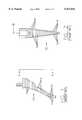
- FIGS. 1 and 2show a typical broaching tool and prior art FIGS. 3-5 show a typical reaming tool.
- the broacher 10 shown in FIGS. 1 and 2generally includes a plurality of parallel teeth 12, each having a sharp distal cutting edge 14 which is formed by distal flaring.
- the teeth 12are spaced along an axis 16 of the broacher and the broacher is typically asymmetrical about the axis 16 as shown by comparing FIGS. 1 and 2. As such, the broacher 12 is well suited for creating an asymmetrical canal.
- the broacher 10is generally introduced into a pre-drilled bone canal with the aid of an impactor tool such as a hammer (not shown).
- the sharp edges 14 of the teeth 12engage cancellous bone axially and displace the soft bone material within the canal.
- the broaching proceduremay displace cancellous bone material within the bone in order to create a cavity for receipt of the stem of an implant.
- the asymmetrical geometry of the broacher 10may be considered either an advantage or a disadvantage depending on the surgical situation.
- the displacement of cancellous bone without removing itmay also be considered an advantage or a disadvantage depending on the particular surgical situation. If the bone is structurally weak, it may be desirable to avoid removing any of the cancellous bone material. If the bone is not weak and the cancellous bone material is diseased, it may be more desirable to remove the cancellous bone material.
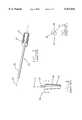
- the reamer 20 shown in FIGS. 3-5is generally symmetrical about its longitudinal axis 22 and is provided with at least one substantially longitudinal flute 24 defining a sharp cutting edge 26 which extends generally longitudinally along substantially the entire cutting portion of the tool.
- the reamer 20has a shaft 28 which allows it to be rotated about its longitudinal axis 22 with the aid of a handle or a motor (not shown).
- the reamermay be provided with plural flutes and the flutes may be helically arranged. Moreover, each flute may define either one or two cutting edges. If the flutes each define only one cutting edge, the reamer will cut bone only when rotated in one (clockwise or counter-clockwise) direction. If the flutes each define two cutting edges, the reamer will cut bone when rotated in either (clockwise or counter-clockwise) direction. The cutting edges in the reamer engage the cancellous bone radially and usually displace the cut bone axially to the proximal end of the tool such that the bone is removed from the reamed canal.
- the symmetrical geometry of the reamer 20may be considered either an advantage or a disadvantage depending on the surgical situation.
- the removal of cancellous when creating a cavity for the stem of an implantmay also be considered an advantage or a disadvantage depending on the particular surgical situation.
- broachers and reamersare mutually exclusive. For example, if it is desirable to create a symmetrical cavity without removing cancellous bone material, neither the broacher nor the reamer may accomplish that result. Moreover, if it is desirable to remove some, but not all, cancellous bone material, a surgeon may need to use both a broacher and a reamer in the same bone canal.
- the combination broacher-reamer of the present inventionincludes a generally longitudinally symmetrical cutting tool which is provided with a plurality of longitudinal broaching cutting teeth as well as a plurality of axial reaming cutting teeth.
- the broacher-reameris generally cylindrical with a smooth blunt distal tip and a tapered distal cutting portion.
- a handle(fixed or removable) is provided below the proximal end of the tool and one or more witness marks are provided on the shaft of the tool between the handle and the cutting portion.
- An exemplary broacher-reamer according to the inventionis approximately 6.78 inches long with an overall maximum diameter of approximately 0.843 inches.
- the proximal end of the tool, prior to assembly,has a diametrical throughbore which is dimensioned to receive the handle which is approximately 3.94 inches long.
- the cutting portion of the toolbegins approximately 3.0 inches distal of the proximal end and terminates approximately 1.25 inches short of the blunt smooth distal end of the tool.
- the broaching cutting teethare spaced approximately 0.090 inches apart (i.e., have a pitch of approximately 0.090), have a land width of approximately 0.010 inches, are flared at an angle of approximately 40 degrees, are approximately 0.060 inches deep, and have a tooth fillet radius of approximately 0.020 inches.
- the reaming cutting teethare arranged in a plurality of helical paths which transect the broaching teeth, each helical path being offset from an adjacent path by approximately 36 degrees and having a right hand helix angle of approximately 28 degrees.
- the flutes of the reaming teethare the same depth as and interrupted by the spaces (fillets) between the broaching teeth.
- FIG. 1is a broken side elevation view of a prior art broacher
- FIG. 2is a view taken along line 2--2 of the broacher of FIG. 1;
- FIG. 3is a perspective view of a prior art reamer
- FIG. 4is a broken side elevation view of the prior art reamer of FIG. 3;
- FIG. 5is a view taken along line 5--5 in FIG. 4;
- FIG. 6is a side elevation view of a combination broacher-reamer according to the invention.
- FIG. 7is a view similar to FIG. 6 of a presently preferred embodiment of the invention.
- FIG. 8is a side elevation view of the broacher-reamer of FIG. 7 with the handle removed;
- FIG. 9is an enlarged section taken along the line 9--9 in FIG. 8;
- FIG. 10is a view taken along the line 10--10 in FIG. 8;
- FIG. 11is a broken enlarged section taken along the line 11--11 in FIG. 8;
- FIG. 12is an enlarged view of the circled detail "A" in FIG. 10.
- FIG. 13is an enlarged view of the circled detail "B" in FIG. 10.
- a combination broacher-reamer 30includes a generally longitudinally symmetrical cutting tool having a shank 32, a plurality of longitudinal broaching cutting teeth 34 as well as a plurality of axial reaming cutting teeth 36.
- the broacher-reamer 30is generally cylindrical with a smooth blunt distal tip 38 and a tapered distal cutting portion 40.
- the shank 32 of the toolis provided with a handle 42 and one or more witness marks 44 are provided on the shank of the tool. If the handle is removable shank 32 of the tool may be coupled to a motor or impacting tool.
- the witness marksare provided as an indication to the surgeon of the depth of the canal being reamed/broached.
- FIGS. 7-13illustrate a presently preferred embodiment 50 of a broacher-reamer according to the invention.
- the broacher-reamer 50includes a generally longitudinally symmetrical cutting tool having a shank 52, a plurality of longitudinal broaching cutting teeth 54 as well as a plurality of axial reaming cutting teeth 56.
- the broacher-reamer 50is generally cylindrical with a smooth blunt distal tip 58 and a tapered distal cutting portion 60.
- the shank 52 of the toolis provided with a removable handle 62 and one or more witness marks 64 are provided on the shank 52 of the tool. It will be appreciated that the broacher-reamer 50 is similar to the broacher reamer 30 but with some apparent differences.
- the broacher-reamer 50is the presently preferred embodiment of the invention and the embodiment shown in FIG. 6 is a prototype of the concept of the invention.
- the presently preferred broacher-reamer 50is approximately 6.78 inches long with an overall maximum diameter of approximately 0.843 inches and a minimum diameter of approximately 0.428 inches.
- the proximal end of the shank 52prior to assembly, has a diametrical throughbore 66 which is dimensioned to receive the removable handle (62 in FIG. 7) which is approximately 3.94 inches long with a diameter of approximately 0.375 inches.
- the shank portion 52 of the tool 50is approximately 3.0 inches long and the blunt smooth distal end of the tool is approximately 1.25 inches long.
- the broaching cutting teeth 54are spaced approximately 0.090 inches apart (i.e., have a pitch of approximately 0.090), have a land width of approximately 0.010 inches, are flared at an angle of approximately 40 degrees (with a clearance angle of approximately 0 degrees 37 minutes, are approximately 0.060 inches deep, and have a tooth fillet radius of approximately 0.020 inches.
- the reaming cutting teeth 56are arranged in a plurality of helical paths which transect the broaching teeth 54, each helical path being offset from an adjacent path by approximately 36 degrees and having a right hand helix angle of approximately 28 degrees.
- the flutes of the reaming teeth 56are the same depth as and are interrupted by the spaces (fillets) between the broaching teeth 54.
- the cutting teeth 54 and 56are diametrically tapered toward the smooth distal tip 58 of the tool 50.
- the taperingis effected along a first convex radius of approximately 1.75 inches and a second concave radius of approximately 1.25 inches which reduces the diameter of the tool 50 from its maximum diameter of 0.843 inches to its minimum diameter of 0.428 inches.
- the taperingresults in the reaming teeth 56 being discontinued at a point spaced apart from the smooth blunt tip portion 58 and provides approximately four distal broaching teeth which are not transected by reaming teeth. It will be appreciated that the four distal broaching teeth have land diameters substantially equal to the minimum diameter (0.428) of the tool.
- the witness mark 64is used to indicate to the practitioner the depth to which the tool 50 has been inserted into a bone canal.
- the marks shown in the FIGS.are engraved to a depth of approximately 0.025 inches and are located at 11 mm and 15 mm from the distal end of the shank 52.
- the combination broacher-reamer of the inventionallows the broaching of a symmetrical cavity and allow the surgeon to combine broaching and reaming in a single operation such that some, but not all of the cancellous bone may be removed from the canal.
Landscapes
- Health & Medical Sciences (AREA)
- Surgery (AREA)
- Life Sciences & Earth Sciences (AREA)
- Biomedical Technology (AREA)
- Medical Informatics (AREA)
- Orthopedic Medicine & Surgery (AREA)
- Oral & Maxillofacial Surgery (AREA)
- Engineering & Computer Science (AREA)
- Dentistry (AREA)
- Heart & Thoracic Surgery (AREA)
- Nuclear Medicine, Radiotherapy & Molecular Imaging (AREA)
- Molecular Biology (AREA)
- Animal Behavior & Ethology (AREA)
- General Health & Medical Sciences (AREA)
- Public Health (AREA)
- Veterinary Medicine (AREA)
- Surgical Instruments (AREA)
Abstract
Description
Claims (21)
Priority Applications (1)
| Application Number | Priority Date | Filing Date | Title |
|---|---|---|---|
| US09/066,243US5931841A (en) | 1998-04-24 | 1998-04-24 | Combination broacher-reamer for use in orthopaedic surgery |
Applications Claiming Priority (1)
| Application Number | Priority Date | Filing Date | Title |
|---|---|---|---|
| US09/066,243US5931841A (en) | 1998-04-24 | 1998-04-24 | Combination broacher-reamer for use in orthopaedic surgery |
Publications (1)
| Publication Number | Publication Date |
|---|---|
| US5931841Atrue US5931841A (en) | 1999-08-03 |
Family
ID=22068233
Family Applications (1)
| Application Number | Title | Priority Date | Filing Date |
|---|---|---|---|
| US09/066,243Expired - LifetimeUS5931841A (en) | 1998-04-24 | 1998-04-24 | Combination broacher-reamer for use in orthopaedic surgery |
Country Status (1)
| Country | Link |
|---|---|
| US (1) | US5931841A (en) |
Cited By (34)
| Publication number | Priority date | Publication date | Assignee | Title |
|---|---|---|---|---|
| US6319256B1 (en)* | 1999-03-04 | 2001-11-20 | Sulzer Orthopedics Ltd. | Bone rasp for a femur head prosthesis |
| US6443956B1 (en)* | 2000-09-22 | 2002-09-03 | Mekanika, Inc. | Vertebral drill bit and inserter |
| US6540752B1 (en)* | 1999-11-01 | 2003-04-01 | Greg Hicken | Threaded bone tunnel dilator |
| US20030171756A1 (en)* | 2002-02-12 | 2003-09-11 | Fallin T. Wade | Surgical milling instrument for shaping a bone cavity |
| FR2839878A1 (en)* | 2002-05-23 | 2003-11-28 | Beguec Pierre Le | Preparation of a femur bone, for a press fit prosthesis without cement, a modular rasp is used with a standard distal section and a variety of proximal sections for selection, used with a neutral linear gauge and scale markings |
| US20040019383A1 (en)* | 2002-05-23 | 2004-01-29 | Beguec Pierre Le | Test system for femur prostheses |
| US6764492B2 (en) | 2001-09-10 | 2004-07-20 | Zimmer Technology, Inc. | Bone impaction instrument |
| US20040249384A1 (en)* | 2003-02-04 | 2004-12-09 | Blaha J. David | Compacting broach |
| US20050288676A1 (en)* | 2004-06-29 | 2005-12-29 | Barry Schnieders | Minimally invasive bone broach |
| US20060106393A1 (en)* | 2004-11-12 | 2006-05-18 | Huebner Randall J | Bone reamer |
| US7179259B1 (en) | 2004-06-04 | 2007-02-20 | Biomet Manufacturing Corp. | Instrument assembly for lateral implant |
| GB2430396A (en)* | 2005-09-23 | 2007-03-28 | Thomas Hoogland | A surgical drill |
| US20080195103A1 (en)* | 2007-02-09 | 2008-08-14 | Lawis Randall J | Hollow reamer for medical applications |
| US7488327B2 (en) | 2004-04-12 | 2009-02-10 | Synthes (U.S.A.) | Free hand drill guide |
| USD598096S1 (en) | 2009-03-13 | 2009-08-11 | Orthopedic Development Corporation | Surgical broach |
| US7641698B1 (en) | 2004-06-04 | 2010-01-05 | Biomet Manufacturing Corp. | Modular hip joint implant |
| US20100262146A1 (en)* | 2009-04-09 | 2010-10-14 | Howmedica Osteonics Corp. | Disposable bone cutting instrument |
| CN103445828A (en)* | 2012-05-30 | 2013-12-18 | 德普伊(爱尔兰)有限公司 | Tibial orthopedic surgical instrument and method of use thereof |
| US20140276850A1 (en)* | 2013-03-15 | 2014-09-18 | Rebecca L. Chaney | Femoral surgical instrument and method of using same |
| US9011444B2 (en) | 2011-12-09 | 2015-04-21 | Howmedica Osteonics Corp. | Surgical reaming instrument for shaping a bone cavity |
| US9149282B2 (en) | 2011-12-30 | 2015-10-06 | Howmedica Osteonics Corp. | Systems and methods for preparing bone voids to receive a prosthesis |
| US9526513B2 (en) | 2013-03-13 | 2016-12-27 | Howmedica Osteonics Corp. | Void filling joint prosthesis and associated instruments |
| US9554810B2 (en) | 2013-03-15 | 2017-01-31 | Depuy Ireland Unlimited Company | Femoral system handle surgical instrument and method of assembling same |
| USD778443S1 (en)* | 2015-03-31 | 2017-02-07 | James Brannon | Bone coring trephine |
| US20170245958A1 (en)* | 2016-02-26 | 2017-08-31 | Douglas Bruce Smail | Dental Bur |
| US9962173B2 (en) | 2012-05-30 | 2018-05-08 | Depuy Ireland Unlimited Company | Surgical instruments and method of surgically preparing a patient's tibia |
| US10363148B2 (en) | 2016-05-18 | 2019-07-30 | Depuy Ireland Unlimited Company | Method for preparing a patient's femur in an orthopaedic joint replacement procedure |
| US10470898B2 (en) | 2016-05-18 | 2019-11-12 | Depuy Ireland Unlimited Company | Orthopaedic instrument system for surgically-preparing a patient's tibia |
| US10537440B2 (en) | 2016-05-18 | 2020-01-21 | Depuy Ireland Unlimited Company | Method of using an orthopaedic instrument system in surgically-preparing a patient's femur |
| US10537341B2 (en) | 2017-09-20 | 2020-01-21 | Depuy Ireland Unlimited Company | Orthopaedic system and method for assembling prosthetic components |
| US10537446B2 (en) | 2017-09-20 | 2020-01-21 | Depuy Ireland Unlimited Company | Method and instruments for assembling an orthopaedic prosthesis |
| US10543001B2 (en) | 2017-09-20 | 2020-01-28 | Depuy Ireland Unlimited Company | Method and instruments for assembling a femoral orthopaedic prosthesis |
| US11173034B2 (en) | 2015-01-12 | 2021-11-16 | Howmedica Osteonics Corp. | Bone void forming apparatus |
| US11439409B2 (en) | 2019-09-18 | 2022-09-13 | Depuy Ireland Unlimited Company | Cutting block |
Citations (5)
| Publication number | Priority date | Publication date | Assignee | Title |
|---|---|---|---|---|
| US2643443A (en)* | 1950-12-09 | 1953-06-30 | Francis J Lapointe | Broach |
| US4124026A (en)* | 1976-05-14 | 1978-11-07 | Deutsche Gardner-Denver Gmbh | Procedure and apparatus for screwing implants into bones |
| US4552136A (en)* | 1983-10-19 | 1985-11-12 | Howmedica, Inc. | Femoral rasp |
| US5041118A (en)* | 1989-04-28 | 1991-08-20 | Implant Technology Inc. | Femoral broach |
| US5503506A (en)* | 1993-06-24 | 1996-04-02 | Hughes Aircraft Company | High precision, high surface finish broaching tool |
- 1998
- 1998-04-24USUS09/066,243patent/US5931841A/ennot_activeExpired - Lifetime
Patent Citations (5)
| Publication number | Priority date | Publication date | Assignee | Title |
|---|---|---|---|---|
| US2643443A (en)* | 1950-12-09 | 1953-06-30 | Francis J Lapointe | Broach |
| US4124026A (en)* | 1976-05-14 | 1978-11-07 | Deutsche Gardner-Denver Gmbh | Procedure and apparatus for screwing implants into bones |
| US4552136A (en)* | 1983-10-19 | 1985-11-12 | Howmedica, Inc. | Femoral rasp |
| US5041118A (en)* | 1989-04-28 | 1991-08-20 | Implant Technology Inc. | Femoral broach |
| US5503506A (en)* | 1993-06-24 | 1996-04-02 | Hughes Aircraft Company | High precision, high surface finish broaching tool |
Cited By (93)
| Publication number | Priority date | Publication date | Assignee | Title |
|---|---|---|---|---|
| US6319256B1 (en)* | 1999-03-04 | 2001-11-20 | Sulzer Orthopedics Ltd. | Bone rasp for a femur head prosthesis |
| US6540752B1 (en)* | 1999-11-01 | 2003-04-01 | Greg Hicken | Threaded bone tunnel dilator |
| US20040064143A1 (en)* | 1999-11-01 | 2004-04-01 | Greg Hicken | Threaded bone tunnel dilator |
| US6443956B1 (en)* | 2000-09-22 | 2002-09-03 | Mekanika, Inc. | Vertebral drill bit and inserter |
| US6764492B2 (en) | 2001-09-10 | 2004-07-20 | Zimmer Technology, Inc. | Bone impaction instrument |
| US7090677B2 (en) | 2002-02-12 | 2006-08-15 | Medicine Lodge, Inc. | Surgical milling instrument for shaping a bone cavity |
| US20030171756A1 (en)* | 2002-02-12 | 2003-09-11 | Fallin T. Wade | Surgical milling instrument for shaping a bone cavity |
| FR2839878A1 (en)* | 2002-05-23 | 2003-11-28 | Beguec Pierre Le | Preparation of a femur bone, for a press fit prosthesis without cement, a modular rasp is used with a standard distal section and a variety of proximal sections for selection, used with a neutral linear gauge and scale markings |
| EP1366721A1 (en)* | 2002-05-23 | 2003-12-03 | Centerpulse Orthopedics Ltd. | Apparatus for preparing a femur bone for implanting a prosthesis |
| US20040019383A1 (en)* | 2002-05-23 | 2004-01-29 | Beguec Pierre Le | Test system for femur prostheses |
| EP1366722A3 (en)* | 2002-05-23 | 2007-11-14 | Zimmer GmbH | Apparatus for the preparation of a femur bone for the implantation of a prothesis |
| US20040249384A1 (en)* | 2003-02-04 | 2004-12-09 | Blaha J. David | Compacting broach |
| US8343195B2 (en) | 2004-04-12 | 2013-01-01 | Synthes Usa, Llc | Drill-tap-screw drill guide |
| US7488327B2 (en) | 2004-04-12 | 2009-02-10 | Synthes (U.S.A.) | Free hand drill guide |
| US8066779B2 (en) | 2004-06-04 | 2011-11-29 | Biomet Manufacturing Corp. | Modular hip joint implant |
| US7179259B1 (en) | 2004-06-04 | 2007-02-20 | Biomet Manufacturing Corp. | Instrument assembly for lateral implant |
| US20100114324A1 (en)* | 2004-06-04 | 2010-05-06 | Biomet Manufacturing Corp. | Modular Hip Joint Implant |
| US7641698B1 (en) | 2004-06-04 | 2010-01-05 | Biomet Manufacturing Corp. | Modular hip joint implant |
| US7632273B2 (en)* | 2004-06-29 | 2009-12-15 | Depuy Products, Inc. | Minimally invasive bone broach |
| US8562609B2 (en) | 2004-06-29 | 2013-10-22 | DePuy Synthes Products, LLC | Minimally invasive bone broach |
| US20050288676A1 (en)* | 2004-06-29 | 2005-12-29 | Barry Schnieders | Minimally invasive bone broach |
| US20100094295A1 (en)* | 2004-06-29 | 2010-04-15 | Depuy Products, Inc. | Minimally Invasive Bone Broach |
| US7927332B2 (en)* | 2004-11-12 | 2011-04-19 | Acumed Llc | Bone reamer |
| US20060106393A1 (en)* | 2004-11-12 | 2006-05-18 | Huebner Randall J | Bone reamer |
| KR101333472B1 (en)* | 2005-09-23 | 2013-11-26 | 토마스 후그란드 | A surgical drill, a set of surgical drills, a system for cutting bone and a method for removing bone |
| WO2007039141A3 (en)* | 2005-09-23 | 2007-08-09 | Thomas Hoogland | A surgical drill, a set of surgical drills, a system for cutting bone and a method for removing bone |
| CN101267774B (en)* | 2005-09-23 | 2012-01-25 | 霍格兰德·托马斯 | Surgical drill, surgical drill set, system for cutting bone |
| US20070093841A1 (en)* | 2005-09-23 | 2007-04-26 | Thomas Hoogland | Surgical drill, a set of surgical drills, a system for cutting bone and a method for removing bone |
| GB2430396A (en)* | 2005-09-23 | 2007-03-28 | Thomas Hoogland | A surgical drill |
| US8535316B2 (en) | 2007-02-09 | 2013-09-17 | Randall J. Lewis | Hollow reamer for medical applications |
| US20080195103A1 (en)* | 2007-02-09 | 2008-08-14 | Lawis Randall J | Hollow reamer for medical applications |
| WO2008100413A1 (en)* | 2007-02-09 | 2008-08-21 | Lewis Randall J | Hollow reamer for medical applications |
| USD598096S1 (en) | 2009-03-13 | 2009-08-11 | Orthopedic Development Corporation | Surgical broach |
| US20100262146A1 (en)* | 2009-04-09 | 2010-10-14 | Howmedica Osteonics Corp. | Disposable bone cutting instrument |
| USRE48163E1 (en) | 2011-12-09 | 2020-08-18 | Howmedica Osteonics Corp. | Surgical reaming instrument for shaping a bone cavity |
| USRE47149E1 (en) | 2011-12-09 | 2018-12-04 | Howmedica Osteonics Corp. | Surgical reaming instrument for shaping a bone cavity |
| US9011444B2 (en) | 2011-12-09 | 2015-04-21 | Howmedica Osteonics Corp. | Surgical reaming instrument for shaping a bone cavity |
| US12262899B2 (en) | 2011-12-30 | 2025-04-01 | Howmedica Osteonics Corp. | Systems and methods for preparing bone voids to receive a prosthesis |
| US9149282B2 (en) | 2011-12-30 | 2015-10-06 | Howmedica Osteonics Corp. | Systems and methods for preparing bone voids to receive a prosthesis |
| US11172940B2 (en) | 2011-12-30 | 2021-11-16 | Howmedica Osteonics Corp. | Systems and methods for preparing bone voids to receive a prosthesis |
| US10265083B2 (en) | 2011-12-30 | 2019-04-23 | Howmedica Osteonics Corp. | Systems and methods for preparing bone voids to receive a prosthesis |
| US10213215B2 (en) | 2011-12-30 | 2019-02-26 | Howmedica Osteonics Corp. | Systems and methods for preparing bone voids to receive a prosthesis |
| US11877757B2 (en) | 2011-12-30 | 2024-01-23 | Howmedica Osteonics Corp. | Systems and methods for preparing bone voids to receive a prosthesis |
| US9962173B2 (en) | 2012-05-30 | 2018-05-08 | Depuy Ireland Unlimited Company | Surgical instruments and method of surgically preparing a patient's tibia |
| US11207085B2 (en) | 2012-05-30 | 2021-12-28 | Depuy Ireland Unlimited Company | Surgical instruments and methods of surgically preparing a patient's tibia |
| US10271862B2 (en) | 2012-05-30 | 2019-04-30 | Depuy Ireland Unlimited Company | Surgical instruments and methods of surgically preparing a patient's tibia |
| CN103445828B (en)* | 2012-05-30 | 2018-02-23 | 德普伊爱尔兰无限公司 | Tibial orthopedic surgical instrument and method of use thereof |
| CN103445828A (en)* | 2012-05-30 | 2013-12-18 | 德普伊(爱尔兰)有限公司 | Tibial orthopedic surgical instrument and method of use thereof |
| US11857205B2 (en) | 2013-03-13 | 2024-01-02 | Howmedica Osteonics Corp. | Void filling joint prosthesis and associated instruments |
| US11357518B2 (en) | 2013-03-13 | 2022-06-14 | Howmedica Osteonics Corp. | Void filling joint prosthesis and associated instruments |
| US9668758B2 (en) | 2013-03-13 | 2017-06-06 | Howmedica Osteonics Corp. | Void filling joint prosthesis and associated instruments |
| US9526513B2 (en) | 2013-03-13 | 2016-12-27 | Howmedica Osteonics Corp. | Void filling joint prosthesis and associated instruments |
| US11172941B2 (en) | 2013-03-13 | 2021-11-16 | Howmedica Osteonics Corp. | Void filling joint prosthesis and associated instruments |
| US10335171B2 (en) | 2013-03-13 | 2019-07-02 | Howmedica Osteonics Corp. | Void filling joint prosthesis and associated instruments |
| US10524806B2 (en) | 2013-03-13 | 2020-01-07 | Howmedica Osteonics Corp. | Void filling joint prosthesis and associated instruments |
| US12274455B2 (en) | 2013-03-13 | 2025-04-15 | Howmedica Osteonics Corp. | Void filling joint prosthesis and associated instruments |
| US12121243B2 (en) | 2013-03-13 | 2024-10-22 | Howmedica Osteonics Corp. | Void filling joint prosthesis and associated instruments |
| US9730706B2 (en)* | 2013-03-15 | 2017-08-15 | Depuy Ireland Unlimited Company | Method of using a femoral surgical instrument |
| US20140276850A1 (en)* | 2013-03-15 | 2014-09-18 | Rebecca L. Chaney | Femoral surgical instrument and method of using same |
| US12426899B2 (en) | 2013-03-15 | 2025-09-30 | Depuy Ireland Unlimited Company | Femoral surgical instrument and method of assembling same |
| US11596420B2 (en) | 2013-03-15 | 2023-03-07 | Depuy Ireland Unlimited Company | Femoral surgical instrument and method of assembling same |
| US9554810B2 (en) | 2013-03-15 | 2017-01-31 | Depuy Ireland Unlimited Company | Femoral system handle surgical instrument and method of assembling same |
| US9113918B2 (en)* | 2013-03-15 | 2015-08-25 | Depuy (Ireland) | Femoral surgical instrument and method of using same |
| US10568644B2 (en) | 2013-03-15 | 2020-02-25 | Depuy Ireland Unlimited Company | Femoral system handle surgical instrument and method of assembling same |
| US20160015399A1 (en)* | 2013-03-15 | 2016-01-21 | Depuy (Ireland) | Method of using a femoral surgical instrument |
| US11173034B2 (en) | 2015-01-12 | 2021-11-16 | Howmedica Osteonics Corp. | Bone void forming apparatus |
| US12121441B2 (en) | 2015-01-12 | 2024-10-22 | Howmedica Osteonics Corp. | Bone void forming apparatus |
| USD778443S1 (en)* | 2015-03-31 | 2017-02-07 | James Brannon | Bone coring trephine |
| US10238469B2 (en)* | 2016-02-26 | 2019-03-26 | Douglas Bruce Smail | Bone reduction bur |
| US20170245958A1 (en)* | 2016-02-26 | 2017-08-31 | Douglas Bruce Smail | Dental Bur |
| US10390965B2 (en) | 2016-05-18 | 2019-08-27 | Depuy Ireland Unlimited Company | System for preparing a patient's femur in an orthopaedic joint replacement procedure |
| US12059361B2 (en) | 2016-05-18 | 2024-08-13 | Depuy Ireland Unlimited Company | System for preparing a patient's tibia in an orthopaedic joint replacement procedure |
| US10537439B2 (en) | 2016-05-18 | 2020-01-21 | Depuy Ireland Unlimited Company | Orthopaedic instrument system for surgically-preparing a patient's femur |
| US11234841B2 (en) | 2016-05-18 | 2022-02-01 | Depuy Ireland Unlimited Company | System and method of performing a reaming operation on a patient's femur during an orthopaedic joint replacement procedure |
| US11337828B2 (en) | 2016-05-18 | 2022-05-24 | Depuy Ireland Unlimited Company | System for preparing a patient's femur in an orthopaedic joint replacement procedure |
| US10363148B2 (en) | 2016-05-18 | 2019-07-30 | Depuy Ireland Unlimited Company | Method for preparing a patient's femur in an orthopaedic joint replacement procedure |
| US11406512B2 (en) | 2016-05-18 | 2022-08-09 | Depuy Ireland Unlimited Company | System and method for surgically-preparing a patient's femur |
| US10363147B2 (en) | 2016-05-18 | 2019-07-30 | Depuy Ireland Unlimited Company | System and method for preparing a patient's femur in an orthopaedic joint replacement procedure |
| US11497620B2 (en) | 2016-05-18 | 2022-11-15 | Depuy Ireland Unlimited Company | System for preparing a patient's tibia in an orthopaedic joint replacement procedure |
| US11504251B2 (en) | 2016-05-18 | 2022-11-22 | Depuy Ireland Unlimited Company | System and method for preparing a patient's femur in an orthopaedic joint replacement procedure |
| US11517448B2 (en) | 2016-05-18 | 2022-12-06 | Depuy Ireland Unlimited Company | Method for preparing a patient's femur in an orthopaedic joint replacement procedure |
| US10390966B2 (en) | 2016-05-18 | 2019-08-27 | Depuy Ireland Unlimited Company | System including femoral augment trials and method of performing an orthopaedic joint replacement procedure |
| US10470898B2 (en) | 2016-05-18 | 2019-11-12 | Depuy Ireland Unlimited Company | Orthopaedic instrument system for surgically-preparing a patient's tibia |
| US10537440B2 (en) | 2016-05-18 | 2020-01-21 | Depuy Ireland Unlimited Company | Method of using an orthopaedic instrument system in surgically-preparing a patient's femur |
| US10492799B2 (en) | 2016-05-18 | 2019-12-03 | Depuy Ireland Unlimited Company | System for preparing a patient's tibia in an orthopaedic joint replacement procedure |
| US12011371B2 (en) | 2016-05-18 | 2024-06-18 | Depuy Ireland Unlimited Company | System and method for surgically-preparing a patient's femur |
| US10470899B2 (en) | 2016-05-18 | 2019-11-12 | Depuy Ireland Unlimited Company | Method for preparing a patient's tibia in an orthopaedic joint replacement procedure |
| US12097128B2 (en) | 2016-05-18 | 2024-09-24 | Depuy Ireland Unlimited Company | System and method for preparing a patient's femur in an orthopaedic joint replacement procedure |
| US10543001B2 (en) | 2017-09-20 | 2020-01-28 | Depuy Ireland Unlimited Company | Method and instruments for assembling a femoral orthopaedic prosthesis |
| US11672547B2 (en) | 2017-09-20 | 2023-06-13 | Depuy Ireland Unlimited Company | Orthopaedic system and method for assembling prosthetic components |
| US10537341B2 (en) | 2017-09-20 | 2020-01-21 | Depuy Ireland Unlimited Company | Orthopaedic system and method for assembling prosthetic components |
| US10537446B2 (en) | 2017-09-20 | 2020-01-21 | Depuy Ireland Unlimited Company | Method and instruments for assembling an orthopaedic prosthesis |
| US11439409B2 (en) | 2019-09-18 | 2022-09-13 | Depuy Ireland Unlimited Company | Cutting block |
Similar Documents
| Publication | Publication Date | Title |
|---|---|---|
| US5931841A (en) | Combination broacher-reamer for use in orthopaedic surgery | |
| US7927332B2 (en) | Bone reamer | |
| US5665090A (en) | Bone cutting apparatus and method | |
| US6264657B1 (en) | Method for removing devices from bone | |
| EP0700272B1 (en) | Flexible medullary reaming system | |
| EP0570500B1 (en) | Reamer | |
| US12295854B2 (en) | Annular cutting tools for resecting a bone graft and related methods | |
| US8535316B2 (en) | Hollow reamer for medical applications | |
| JP2003169810A (en) | Chisel for vertebral terminal plate | |
| JPH04227250A (en) | Cutting head | |
| JP7210688B2 (en) | surgical rotary cutting tool | |
| US8403931B2 (en) | Modular tapered hollow reamer for medical applications | |
| US20140081274A1 (en) | Hybrid femoral hip stem broach | |
| US20150119893A1 (en) | Method And Apparatus For Preparing An Implantation Site | |
| CN110461256B (en) | Guiding osteotome | |
| JP2020036948A (en) | Surgical bur with single cutting flute | |
| JPH1043199A (en) | Tap for orthopedics | |
| JP3916417B2 (en) | Bone drill and bone reamer | |
| JP7398850B1 (en) | bone extractor | |
| AU2012201575A1 (en) | Hollow reamer for medical applications |
Legal Events
| Date | Code | Title | Description |
|---|---|---|---|
| AS | Assignment | Owner name:HOWMEDICA INC., NEW YORK Free format text:ASSIGNMENT OF ASSIGNORS INTEREST;ASSIGNOR:RALPH, CHRISTOPHER R.;REEL/FRAME:009164/0743 Effective date:19980420 | |
| STCF | Information on status: patent grant | Free format text:PATENTED CASE | |
| AS | Assignment | Owner name:STRYKER TECHNOLOGIES CORPORATION, MICHIGAN Free format text:ASSIGNMENT OF ASSIGNORS INTEREST;ASSIGNOR:MTG DIVESTITURES INC., A CORPORATION OF DELAWARE;REEL/FRAME:010277/0317 Effective date:19990924 Owner name:MTG DIVESTITURES INC., NEW YORK Free format text:CHANGE OF NAME;ASSIGNOR:HOWMEDICA INC.;REEL/FRAME:010277/0659 Effective date:19981203 | |
| CC | Certificate of correction | ||
| FPAY | Fee payment | Year of fee payment:4 | |
| AS | Assignment | Owner name:HOWMEDICA OSTEONICS CORP., NEW JERSEY Free format text:ASSIGNMENT OF ASSIGNORS INTEREST;ASSIGNOR:STRYKER TECHNOLOGIES CORPORATION;REEL/FRAME:015044/0484 Effective date:20031217 | |
| FPAY | Fee payment | Year of fee payment:8 | |
| FPAY | Fee payment | Year of fee payment:12 |