US5931808A - Cassette for endoscope - Google Patents
Cassette for endoscopeDownload PDFInfo
- Publication number
- US5931808A US5931808AUS08/922,225US92222597AUS5931808AUS 5931808 AUS5931808 AUS 5931808AUS 92222597 AUS92222597 AUS 92222597AUS 5931808 AUS5931808 AUS 5931808A
- Authority
- US
- United States
- Prior art keywords
- pump
- pressure
- body cavity
- fluid
- internal body
- Prior art date
- Legal status (The legal status is an assumption and is not a legal conclusion. Google has not performed a legal analysis and makes no representation as to the accuracy of the status listed.)
- Expired - Lifetime
Links
Images


Classifications
- A—HUMAN NECESSITIES
- A61—MEDICAL OR VETERINARY SCIENCE; HYGIENE
- A61B—DIAGNOSIS; SURGERY; IDENTIFICATION
- A61B1/00—Instruments for performing medical examinations of the interior of cavities or tubes of the body by visual or photographical inspection, e.g. endoscopes; Illuminating arrangements therefor
- A61B1/00002—Operational features of endoscopes
- A61B1/00043—Operational features of endoscopes provided with output arrangements
- A61B1/00045—Display arrangement
- A61B1/00048—Constructional features of the display
- A—HUMAN NECESSITIES
- A61—MEDICAL OR VETERINARY SCIENCE; HYGIENE
- A61B—DIAGNOSIS; SURGERY; IDENTIFICATION
- A61B1/00—Instruments for performing medical examinations of the interior of cavities or tubes of the body by visual or photographical inspection, e.g. endoscopes; Illuminating arrangements therefor
- A61B1/00002—Operational features of endoscopes
- A61B1/00039—Operational features of endoscopes provided with input arrangements for the user
- A61B1/0004—Operational features of endoscopes provided with input arrangements for the user for electronic operation
- A—HUMAN NECESSITIES
- A61—MEDICAL OR VETERINARY SCIENCE; HYGIENE
- A61B—DIAGNOSIS; SURGERY; IDENTIFICATION
- A61B1/00—Instruments for performing medical examinations of the interior of cavities or tubes of the body by visual or photographical inspection, e.g. endoscopes; Illuminating arrangements therefor
- A61B1/04—Instruments for performing medical examinations of the interior of cavities or tubes of the body by visual or photographical inspection, e.g. endoscopes; Illuminating arrangements therefor combined with photographic or television appliances
- A—HUMAN NECESSITIES
- A61—MEDICAL OR VETERINARY SCIENCE; HYGIENE
- A61B—DIAGNOSIS; SURGERY; IDENTIFICATION
- A61B1/00—Instruments for performing medical examinations of the interior of cavities or tubes of the body by visual or photographical inspection, e.g. endoscopes; Illuminating arrangements therefor
- A61B1/12—Instruments for performing medical examinations of the interior of cavities or tubes of the body by visual or photographical inspection, e.g. endoscopes; Illuminating arrangements therefor with cooling or rinsing arrangements
- A—HUMAN NECESSITIES
- A61—MEDICAL OR VETERINARY SCIENCE; HYGIENE
- A61B—DIAGNOSIS; SURGERY; IDENTIFICATION
- A61B1/00—Instruments for performing medical examinations of the interior of cavities or tubes of the body by visual or photographical inspection, e.g. endoscopes; Illuminating arrangements therefor
- A61B1/313—Instruments for performing medical examinations of the interior of cavities or tubes of the body by visual or photographical inspection, e.g. endoscopes; Illuminating arrangements therefor for introducing through surgical openings, e.g. laparoscopes
- A61B1/3132—Instruments for performing medical examinations of the interior of cavities or tubes of the body by visual or photographical inspection, e.g. endoscopes; Illuminating arrangements therefor for introducing through surgical openings, e.g. laparoscopes for laparoscopy
- A—HUMAN NECESSITIES
- A61—MEDICAL OR VETERINARY SCIENCE; HYGIENE
- A61B—DIAGNOSIS; SURGERY; IDENTIFICATION
- A61B17/00—Surgical instruments, devices or methods
- A61B17/00234—Surgical instruments, devices or methods for minimally invasive surgery
- A—HUMAN NECESSITIES
- A61—MEDICAL OR VETERINARY SCIENCE; HYGIENE
- A61M—DEVICES FOR INTRODUCING MEDIA INTO, OR ONTO, THE BODY; DEVICES FOR TRANSDUCING BODY MEDIA OR FOR TAKING MEDIA FROM THE BODY; DEVICES FOR PRODUCING OR ENDING SLEEP OR STUPOR
- A61M1/00—Suction or pumping devices for medical purposes; Devices for carrying-off, for treatment of, or for carrying-over, body-liquids; Drainage systems
- A61M1/71—Suction drainage systems
- A61M1/72—Cassettes forming partially or totally the fluid circuit
- A—HUMAN NECESSITIES
- A61—MEDICAL OR VETERINARY SCIENCE; HYGIENE
- A61M—DEVICES FOR INTRODUCING MEDIA INTO, OR ONTO, THE BODY; DEVICES FOR TRANSDUCING BODY MEDIA OR FOR TAKING MEDIA FROM THE BODY; DEVICES FOR PRODUCING OR ENDING SLEEP OR STUPOR
- A61M1/00—Suction or pumping devices for medical purposes; Devices for carrying-off, for treatment of, or for carrying-over, body-liquids; Drainage systems
- A61M1/71—Suction drainage systems
- A61M1/77—Suction-irrigation systems
- A—HUMAN NECESSITIES
- A61—MEDICAL OR VETERINARY SCIENCE; HYGIENE
- A61M—DEVICES FOR INTRODUCING MEDIA INTO, OR ONTO, THE BODY; DEVICES FOR TRANSDUCING BODY MEDIA OR FOR TAKING MEDIA FROM THE BODY; DEVICES FOR PRODUCING OR ENDING SLEEP OR STUPOR
- A61M3/00—Medical syringes, e.g. enemata; Irrigators
- A61M3/02—Enemata; Irrigators
- A61M3/0201—Cassettes therefor
- A—HUMAN NECESSITIES
- A61—MEDICAL OR VETERINARY SCIENCE; HYGIENE
- A61M—DEVICES FOR INTRODUCING MEDIA INTO, OR ONTO, THE BODY; DEVICES FOR TRANSDUCING BODY MEDIA OR FOR TAKING MEDIA FROM THE BODY; DEVICES FOR PRODUCING OR ENDING SLEEP OR STUPOR
- A61M1/00—Suction or pumping devices for medical purposes; Devices for carrying-off, for treatment of, or for carrying-over, body-liquids; Drainage systems
- A61M1/80—Suction pumps
- A—HUMAN NECESSITIES
- A61—MEDICAL OR VETERINARY SCIENCE; HYGIENE
- A61M—DEVICES FOR INTRODUCING MEDIA INTO, OR ONTO, THE BODY; DEVICES FOR TRANSDUCING BODY MEDIA OR FOR TAKING MEDIA FROM THE BODY; DEVICES FOR PRODUCING OR ENDING SLEEP OR STUPOR
- A61M2205/00—General characteristics of the apparatus
- A61M2205/12—General characteristics of the apparatus with interchangeable cassettes forming partially or totally the fluid circuit
- A—HUMAN NECESSITIES
- A61—MEDICAL OR VETERINARY SCIENCE; HYGIENE
- A61M—DEVICES FOR INTRODUCING MEDIA INTO, OR ONTO, THE BODY; DEVICES FOR TRANSDUCING BODY MEDIA OR FOR TAKING MEDIA FROM THE BODY; DEVICES FOR PRODUCING OR ENDING SLEEP OR STUPOR
- A61M2205/00—General characteristics of the apparatus
- A61M2205/33—Controlling, regulating or measuring
- A61M2205/3331—Pressure; Flow
- A61M2205/3351—Controlling upstream pump pressure
Definitions
- the present inventionrelates to a method and apparatus for use in surgical procedures, and more particularly to a method and apparatus for use in endoscopic surgical procedures.
- Endoscopic surgeryis a minimally invasive therapeutic and/or diagnostic procedure during which relatively small visualization and surgical tools are introduced into a portion of the human body such as a knee joint through relatively small incisions. Typically, at least three incisions are employed for a therapeutic procedure and at least two are employed for a diagnostic procedure.
- physiological fluidsuch as a sterile saline solution is allowed to flow through the joint so as to distend the joint to facilitate access to the joint.
- the flow of physiological fluid through the jointenhances the clarity of the field of view by removing debris from the surgical site.
- the flow of fluid into the joint during endoscopic surgeryis regulated by two independent but yet related functions. These two functions are the pressure of fluid within the joint and the volume of fluid flowing through the joint.
- the pressure of fluid within the jointdetermines the extent to which the joint is distended. For example, a surgeon may want to increase the pressure of fluid within the joint when the surgeon needs to view or access the end of the joint opposite to the point of insertion of the probe. In contrast, if there is bleeding or debris in the cavity, an increase in the flow rate of fluid is needed to clear the field of view.
- an instrumentsuch as a shaver with a suction tube is used, a greater flow of fluid into the cavity is required to prevent the cavity from collapsing.
- the equipment used for endoscopic surgery in the pasthas been relatively difficult to use.
- a nursegenerally has to connect individual tubes to various cannulas and pumps associated with the system as well as to thread tubes through peristaltic pumps. This is a relatively time consuming activity.
- the surgeonoften has to adjust the pump speed each time the shaver is used. This is because the shaver will draw fluid from the cavity thereby requiring the surgeon to increase the flow rate of fluid into the cavity.
- the light source for illuminating the cavityis functionally independent of the camera used to record the image inside the cavity. Accordingly, the surgeon has to white balance the camera in order to provide a relatively clear image.
- the various parameterssuch as flow rate, cavity pressure, shaver speed and so forth have to be readjusted virtually every time a doctor begins using the equipment after another doctor has finished using the equipment.
- the equipment used for performing surgeryoften uses a shaver handpiece which is subject to certain disadvantages.
- the shaver handpieceis often driven by a motor which is connected by a gear box to the shaver blade.
- the gears within the gear boxcould fail upon receipt of excess torque also tended to cause premature failure of the shaver handpiece.
- the debriswill often plug the shaver handpiece making the handpiece inoperable.
- an advantage of the present inventionis to provide an apparatus for endoscopic surgery which is relatively simple to use.
- a related advantage of the present inventionis to provide an apparatus for endoscopic surgery which minimizes the time required for surgeons and nurses to set up and operate.
- a further advantage of the present inventionis to provide an apparatus for endoscopic surgery in which the pressure within the cavity can be accurately controlled.
- a related advantage of the present inventionis to provide an apparatus for endoscopic surgery in which the irrigation pump controls the flow rate of fluid into the cavity while the aspiration pump is used to control the pressure of fluid within the cavity.
- An additional object of the present inventionis to provide an apparatus for endoscopic surgery in which various parameters associated with operating the apparatus can be stored and retrieved with relative ease.
- a related advantage of the present inventionis to provide an apparatus for endoscopic surgery which is menu driven.
- Another advantage of the present inventionis to provide an apparatus for endoscopic surgery in which debris from the cavity passes through the shaver handpiece in a relatively straight direction.
- Another advantage of the present inventionis to provide an apparatus for endoscopic surgery which uses gear pumps to control the flow of fluid into and out of the cavity without the use of peristaltic pumps.
- the present inventionprovides for an apparatus for endoscopic surgery which utilizes a gear pump for both the irrigation and aspiration of the fluid from the cavity.
- the speed of the irrigation pumpis held generally constant while the speed of the aspiration pump is varied in response to the pressure within the joint.
- Both the irrigation pump and the aspiration pumpare contained in a disposable cassette which is simply inserted into a pump drive unit. Once a flow rate for the irrigation pump is selected, the flow rate of the irrigation pump remains constant. While the input flow rate can be set at various fixed levels during examination, the irrigation pump will automatically be switched to a predetermined input flow rate when a resection tool is used.
- the present inventionfurther includes a pressure sensor which senses the pressure of the fluid in the conduit connecting the irrigation pump to the cavity. The output of the pressure sensor is used for controlling and varying the speed and therefore the suction rate of the aspiration pump. As a result, the pressure in the cavity is maintained at a desired level.
- the present systemmonitors the fluid pressure in the input conduit by using a pressure dome located in the disposable cassette.
- the pressure domerises and falls with increases and decreases of fluid pressure within the cavity respectively.
- the pump drive unitutilizes a proximity sensor for sensing the height of the pressure dome which is then determinative of the fluid pressure.
- Prior art systemsutilize an air column for indicating pressure which is a more complex and fragile system using an orifice which has a tendency to plug during the operation. This sensed pressure of the input conduit is corrected to accurately determine the actual pressure within the cavity.
- Typical endoscopy systemshave a relatively long input conduit. At the same time, the inside diameter of the input conduit is relatively small so as to maintain flexibility. When fluid under pressure flows through the input conduit, a pressure drop occurs through the input conduit.
- This pressure drop through the input conduitwhich may be a relatively large percentage of the pressure within the cavity, will be influenced by the diameter of the input conduit and also by the rate of flow through the input conduit. Accordingly, as the flow rate through the input conduit is varied, the pressure drop through the input conduit will vary correspondingly. For this reason, sensing the pressure in the input conduit alone will not accurately measure the pressure within the cavity because of the pressure drop through the input conduit. It is therefore desirable to be able to reliably determine the pressure drop through the input conduit in order to more accurately provide an indication of (and ultimately control) the pressure within the cavity based upon a pressure measurement taken at the input conduit.
- the irrigation pump of the present inventionis used to provide a fixed, selected flow rate of fluid into the cavity while the aspiration pump, through variable speed, controls pressure
- the present systemhas several important advantages.
- the present systemis able to estimate the pressure in the cavity with greater accuracy by compensating for the pressure drop which occurs through the portion of the input conduit between the pressure sensor and the cavity. This is because the pressure drop through the input conduit is a function of the flow rate through the input conduit which can be easily determined because the irrigation pump establishes the flow rate at a preselected fixed magnitude.
- the pressure drop through the input conduitcan be accurately determined and therefore the output from the pressure sensor located at the outlet of the irrigation pump can more precisely indicate the actual pressure of fluid in the cavity.
- the present systemcan provide a more accurate way for controlling the pressure in that cavity.
- the flow rate through the input conduit (1)would vary as the speed of the input pump continuously changed to maintain the desired pressure within the cavity and (2) would be more difficult to accurately determine because of the continuous variation in flow. Because the flow rate through the input conduit would vary and be difficult to determine, the pressure drop through the input conduit would also vary and be difficult to determine. The output of the pressure sensor would therefore not provide such an accurate estimate of the pressure within the cavity. Accordingly, the fact that the irrigation pump of the present system is used to control the flow at a constant rate while the aspiration pump is used to control pressure allows a more accurate determination of both the magnitude of pressure within the cavity and the volume of flow of fluid into the cavity.
- the irrigation pumpwould have to supply a sufficient amount of fluid to maintain the pressure in the cavity as well as to compensate for fluid leaving the cavity (1) by leakage and (2) through the aspiration pump.
- the capacity of the irrigation pumpcould be exceeded as the irrigation pump attempts to increase the input flow rate to maintain the desired pressure within the cavity while also attempting to compensate for both the leakage out from the cavity as well as the fluid drawn out of the cavity by the aspiration pump.
- the aspiration pumpwere used to provide a fixed flow rate, the amount of fluid flowing into the cavity would also not be as accurately determined because of leakage of fluid from the cavity, the amount of which could vary substantially between different operations.
- the aspiration pump of the present systemis a two-directional gear pump which allows fluid to flow through a first output conduit when the aspiration pump is driven in one direction and allows fluid to flow through a second output conduit when the aspiration pump is driven in a second direction.
- the flow of fluid through the second output conduitoccurs when a resection tool is used.
- This switching of output conduitsis accomplished by a series of check valves which automatically switch the conduits when the direction of the motor is reversed eliminating the need to manually adjust valves or tubing to accommodate the different flow rates coming from the separate conduits.
- both the irrigation pump and the aspiration pumpare gear pumps and are contained in the disposable cassette.
- the use of the disposable cassettesignificantly simplifies the process for getting ready for surgery by providing a one step system of inserting the cassette for engaging the two pumps.
- the use of gear pumps instead of prior art peristaltic pumpsprovides a system which requires less energy and is more efficient.
- a peristaltic pumprequires the tubing to be threaded through the pump in order for the pump to function. Once assembled, most of the energy required for the pump to operate is used to compress the plastic tube and not to pump the liquid. Because the cassette system is disposable, the fluid medium can be introduced into the pump and the cassette then can be simply inserted into the pump drive unit. This one step operation significantly simplifies the steps necessary to get ready for the operation.
- the present systemdoes not have a tachometer per se which measures the speed of the motors that drive the irrigation and aspiration pumps. Rather, the present system measures the frequency of electrical pulses generated in part by the movement of magnets within each of the motors. The frequencies of the electrical pulses are indicative of the speed of their respective motors. These electrical pulses are delivered to a microprocessor which monitors the changing frequencies of the pulses to control the speed of the irrigation and aspiration pump motors.
- the present systemterminates the operation of the irrigation and aspiration pumps when the pressure in the cavity becomes excessive, the present system does not immediately terminate the flow of fluid into the cavity when the pressure in the cavity falls below a predetermined limit. Rather, the aspiration pump progressively reduces its speed in an attempt to maintain the pressure within the cavity at the desired magnitude. This reduction in speed continues up to the point where the operation of the aspiration pump terminates. When this occurs, while flow of fluid into the cavity continues, there is no flow of fluid drawn from the cavity through the aspiration pump and therefore the only flow of fluid out from the cavity is by virtue of leakage.
- FIG. 1is a front view of the apparatus for performing endoscopic surgical procedures according to the preferred embodiment of the present invention
- FIG. 2is a rear view of the apparatus for performing endoscopic surgical procedures according to the preferred embodiment of the present invention
- FIG. 3is an enlarged front view of the imaging unit of the apparatus for performing endoscopic surgical procedures shown in FIG. 1 according to the preferred embodiment of the present invention
- FIG. 4is an enlarged front view of the intra-articular unit of the apparatus for performing endoscopic surgical procedures shown in FIG. 1 according to the preferred embodiment of the present invention
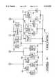
- FIG. 5is a block diagram showing the components of the apparatus for performing endoscopic surgical procedures shown in FIG. 1 according to the preferred embodiment of the present invention
- FIG. 6is a block diagram showing the components of the imaging unit of the apparatus for performing endoscopic surgical procedures shown in FIG. 1 according to the preferred embodiment of the present invention
- FIG. 7is a block diagram showing the components of the intra-articular unit of the apparatus for performing endoscopic surgical procedures shown in FIG. 1 according to the preferred embodiment of the present invention.
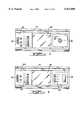
- FIG. 8is a perspective view of the pump cassette which is used with the intra-articular unit shown in FIG. 4 according to the preferred embodiment of the present invention
- FIG. 9is a plan view showing the internal components of the pump cassette shown in FIG. 8 according to the preferred embodiment of the present invention.
- FIG. 10is a plan view partially in cross-section of the internal components of the pump cassette shown in FIG. 8 according to the preferred embodiment of the present invention.
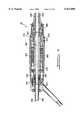
- FIG. 11is a longitudinal cross sectional view partially in cross-section of the shaver handpiece unit shown in FIG. 1 according to the preferred embodiment of the present invention.
- FIGS. 12-14show a flowchart illustrating the various user-driven menus which are generated by the apparatus for performing endoscopic surgical procedures shown in FIG. 1 according to the preferred embodiment of the present invention.
- the apparatus for performing endoscopic examination and resection apparatus of the present inventionis shown in FIGS. 1 and 2 and is generally designated by the numeral 10.
- the apparatus 10comprises an imaging unit 12, an intra-articular unit 14, a keyboard 16, an autoclavable remote control unit 18, a video monitor 20, a video cassette recorder 22, a video printer 24 and a cart 26.
- an imaging unit 12an intra-articular unit 14
- a keyboard 16an autoclavable remote control unit 18
- video monitor 20a video cassette recorder 22
- video printer 24a video printer 24
- cart 26a cart 26.
- the cart 26houses the majority of the components of the apparatus 10.
- the cart 26is pre-wired for easy installation of the imaging unit 12, the intra-articular unit 14, the video cassette recorder 22 and the video printer 24.
- most of the electrical conductors connecting the various components of the apparatus 10are contained internally within the cart 26 and are connected to various electrical connectors mounted on the cart 26.
- the electrical conductors within the cart 26allow the imaging unit 12 to intercommunicate with the intra-articular unit 14 so as to allow the imaging unit 12 to operate interdependently with the intra-articular unit 14.
- the remote control unit 18may be connected to either the imaging unit 12 or the intra-articular unit 14 and can control both.
- the imaging unit 12may be used when the operation of the intra-articular unit 14 is being programmed. Other ways in which the imaging unit 12 and the intra-articular unit 14 operate interdependently are described below.
- the cart 26provides ample storage racks 58 for storage trays, the video cassette recorder 22 and the video printer 24.
- the cart 26is also equipped with an isolation transformer located in the base 60 of the cart 26 which provides for electrical leakage containment of the components within the cart 26.
- the cart 26can be easily maneuvered on its swivel locking caster wheels 62.
- the imaging unit 12 of the apparatus 10 as shown in FIG. 3comprises an RGB monitor 30, a high output xenon light source 32 and a camera 34 all contained in a chassis 36.
- the RGB monitor 30can be used as a programming screen with menu driven control for individual system preferences such as light illumination and picture color as more fully described below. Alternatively, the monitor 30 can be used as a secondary monitor for viewing the surgical procedure.
- System programming of the imaging unit 12is accomplished by utilizing the keyboard 16 as well as by the remote control unit 18 as will also be more fully described below.
- the camera 34has an auto iris which provides instant illumination adjustments to reduce glare while an auto white balance eliminates time consuming camera set-ups.
- the camera 34receives optical signals from a camera head 38 which is connected to the chassis 36 by both a fiber optic cable 39 and an electrical cord 40. Operation of the various functions of the imaging unit 12 can be accomplished by controls on the front panel of the imaging unit 12 or by the remote control unit 18 as described below.
- the intra-articular unit 14 of the apparatus 10 as shown in FIG. 4comprises an RGB monitor 42, a shaver power unit 44 and a pumping unit 48, all of which are contained in a chassis 64.
- the RGB monitor 42provides display of current running information (e.g., the speed of the shaver, fluid flow rate and cavity pressure) and can be utilized for information on operating the apparatus 10. Inflow of fluid from the pumping unit 48 to the cavity can be accomplished through the camera head 38 or by a separate cannula, both utilizing built-in pressure protection.
- the shaver power unit 48is used to drive shaver handpiece 52 (see FIG. 1) which is connected to the chassis 64 by the electrical cord 54. Operation of the various functions can be accomplished by controls on the front panel of the intra-articular unit 14 or also by means of the remote control unit 18 as described below.
- FIG. 5an upper level block diagram of the apparatus 10 is shown depicting the imaging unit 12, the intra-articular unit 14, the video cassette recorder 22, the video printer 24, the video monitor 20, the keyboard 16, an optional bar code wand 72 and the cart 26.
- the components of the imaging unit 12 and the intra-articular unit 14will be more fully discussed below.
- the video monitor 20, normally located on the top of the cart 26,receives the output of the imaging unit 12 and provides a color picture of the endoscopic procedure from the output of the camera head 38.
- Various connectionsare made from the video monitor 20 to the cart 26 to provide video output for the imaging unit 12 as well as receiving output from the video cassette recorder 22. These connections are made through the bus 134 and include RGB video, y/c video input and audio input.
- the video cassette recorder 22is provided to enable the surgeon to make a taped record of the endoscopic examination or procedure.
- the video cassette recorder 22is located in the rear of the cart 26 normally located on one of the storage racks 58.
- Various connectionsare made to the cart 26 for recording and playback of the pictures created by the imaging unit 12. These connections are made through the bus 118 and include composite VCR out, audio in, video cassette recorder control, y/c video, audio out and y/c video out.
- the video printer 24is provided in order to allow the surgeon to have a permanent copy of any picture displayed on the video monitor 20.
- the video printer 24is also located at the rear of the cart 26 on one of the storage racks 58.
- Various connectionsare made through the cart 26 for allowing the video printer 24 to interface with the other components of the imaging unit 12. These connections are made through the bus 128 and include freeze RGB, RGB video in and RS232.
- the bar code wand 72connected to the cart 26 through the wand bus 136.
- the bar code wand 72is used to allow easy and relatively quick readouts of operating room charges, patient charges or other standard information.
- the keyboard 16is also an optional device and is connected to the cart 26 by the keyboard bus 138.
- the remote control unit 18may be connected to either the imaging unit 12 or the intra-articular unit 14. The operation of the remote control unit 18 is identical regardless of where the connection is made.
- the remote control unit 18includes a plurality of push-button switches which control the following operational characteristics of the apparatus 10:
- shaver mode changei.e., forward, reverse, oscillate
- the remote control unit 18is autoclavable and therefore used in the sterile field proximate to the surgical site, the surgeon is able to control the apparatus 10 from the sterile field by using the remote control unit 18.
- the imaging unit 12comprises a camera front panel 142, a light source front panel 144, the light source 32, the RGB monitor 30, a camera MPU 146, and the camera 34. All necessary connections to the other components within the apparatus 10 are located on the rear of the imaging unit 12 and inserting the imaging unit 12 into the cart 26 makes the connections through the use of HypertronicTM zero insertion connectors.
- the insertion of the imaging unit 12makes the following connections through the bus 88 to the cart 26: audio, video cassette recorder control, y/c video, composite video, freeze RGB video, RGB video, RS 232-to-print, remote control unit bus, serial bus (unit-to-unit), wand bus, keyboard bus, serial image unit bus and unit-to-unit enable.
- the camera front panel 142provides an electrical connection to electrically couple the imaging unit 12 to the microphone 74 through the bus 80, the camera head 38 through the bus 116, the polaroid camera 76 through the bus 84 and the remote control unit 18 through the bus 82.
- the camera front panel 142is also electrically coupled to the camera 34 through the bus 120, the camera MPU 146 through the bus 122 and the input power 150.
- All five RS-232 serial ports of the imaging unit 12use a plurality UARTS controlled by the camera MPU 146, each having their own baud rate generator.
- the S-bus outputis a serial data bus with a standard protocol data system generated by the camera MPU 146 using an internal timer. All ports are double buffered allowing the camera MPU 146 to write or read characters irrespective of the peripheral timing.
- the camera MPU 146itself contains multiple pulse modulators which when attached to a low pass filter produce controllable analog voltages. These voltages preferably control the adjustment of a camera iris for the camera 34 as well as the beeper volume.
- Multiple digital input/output lines of the camera MPU 146are used for switch status input, remote scanning, S-bus generation, SIO control, camera control and video multiplexer control.
- the RGB monitor 30 of the imaging unit 12is preferably a 9-inch monitor which displays various menus enabling the surgeon to quickly set or change various operating parameters by using the remote control unit 18.
- Each menuis generated in accordance with a software program 298 (which is described in connection with FIGS. 12 and 13) by the camera MPU 146 and written to the external RAM memory at VIDSTORE, as listed in the Appendix. This data is then downloaded to a video RAM in the MPU 146 during the vertical retrace.
- the various menus displayed on the RGB monitor 30will be more fully described below.
- the video signal generated by the camera MPU 146represents three identical channels of RGB information.
- the video signal from the camera MPU 146is delivered to the video monitor 20, the RGB monitor 30, the video printer 24 and the video cassette recorder 22.
- a composite video signalis delivered to the video cassette recorder 22, with all other peripherals receiving either composite or RGB video.
- the RGB monitor 30preferably displays the video signal from the camera MPU 146 with a computer generated overlay or with freeze images.
- the video printer 24 and the video cassette recorder 22preferably receive a camera image with an overlay generated thereon.
- the overlaysmay represent patient ID or other helpful information relating to the surgical procedure. Selection of the source/destination video and sync is performed by a multiplexer in the video section operating under CPU control.
- the front panel 142 of the camera 34offers various controls for operating the apparatus 10.
- a power switchis electrically coupled to the input power 150 through the fuse block 154.
- the power switchis also electrically coupled to the various power supplies of the imaging unit 12 through an EMI filter 156 and an isolation transformer 158.
- the front panel 142 of the camera 34provides an auto iris on/off switch, a print switch, a scroll up switch, a scroll down switch and an enter switch. All of the above mentioned switches are electrically coupled to the camera MPU 146 through the bus 122.
- the camera MPU 146is preferably a Zilog Z86C97 CMOS digital TV controller containing a Z8 CPU core, on screen display generator, multiple pulse width modulator and parallel input/output ports. Documentation on this microprocessor is available from the manufacturer in the form of the Z86C27/C97 Manual and the Z8 Family Design Handbook, both documents of which are hereby incorporated by reference.
- the imaging unit 12further contains both internal and external random-access memory and an external EPROM program memory.
- a memory mappingmay be found in module EQ, also listed in the Appendix B.
- the imaging unit 12further includes a front panel 144 of the light source 32 which provides a port 170 for connection of the optical fiber cable 39, as well as a lamp-on switch and a lamp-off switch.
- the lamp-on and lamp-off switchescontrol the xenon light source 32 which delivers light to the camera head 38 through the optical fiber cable 39.
- the intra-articular unit 14comprises the shaver power console 46, the pump console 50, the shaver power unit 44, the pumping unit 48, the RGB monitor 42, and a shaver/pump MPU 182. All necessary connections to the other components within the apparatus are located on the rear of the intra-articular unit 14 and inserting the intra-articular unit 14 into the cart 26 makes the connections through the use of HypertronicTM zero insertion connectors 184. In this regard, the insertion of the intra-articular unit 14 into the cart 26 makes the following connections through the bus 108 to the cart 26: serial intra-articular unit bus, data bus (unit-to-unit), remote control unit bus and unit-to-unit enable.
- the shaver power console 46provides electrical connections to electrically couple to the intra-articular unit 14 the shaver handpiece 52 through the bus 104, the foot switch 56 through the bus 106, and the remote control unit 18 through the bus 110.
- the shaver power console 46is also electrically coupled to the shaver motor drive electronics 44 through the bus 90, the shaver/pump MPU 182 through the bus 92 and the input power 186.
- the shaver power console 46includes a power switch which is electrically coupled to the input power 186 through a fuse block 190.
- the power switchis also electrically coupled to the various power supplies of the intra-articular unit 14 through an EMI filter 192 and an isolation transformer 194.
- the RGB monitor 42preferably comprises a 9 inch VGA color monitor which displays real-time system variables in a variety of bar, numeric and message formats.
- the RGB monitor 42may simultaneously display a bar graph of the speed of the shaver handpiece 52, an indication of the mode of operation of the shaver handpiece 52 (forward, reverse or oscillate), as well as an indication of whether the shaver handpiece 52 in on or off.
- the RGB monitor 42may generate a display showing a bar graph of the flow rate of fluid into the cavity as well as the pressure of fluid in the cavity.
- the VGA interface for the RGB monitor 42preferably comprises an industry standard VGA card which is mounted as a daughter board within the intra-articular unit 14.
- the RGB monitor 42provides a high resolution (640 ⁇ 480) pixel VGA map. Due to this high resolution, the intra-articular unit 14 hardware is designed to maximize transfer rate between the shaver/pump MPU 182 and the VGA card in communication with the RGB monitor 42. Maximum data transfer is accomplished by the use of several techniques. First, a memory address-auto increment capability is used to allow CPU-VGA memory transfers without having to load each address prior to each data transfer. In addition, a function decode produces input/output write, input/output read, memory write and memory read pulses with a single input/output instruction. Furthermore, a strobe pulse is generated on either the rise or fall of a generated command. This eliminates the necessity to use two instructions to produce a strobe pulse. In addition, the VGA transfer is synchronized by an automatic weight pulse stretcher. This eliminates the requirement of the CPU to test for VGA ready status.
- the VGA screenis normally mapped as four planes to produce one out of 16 color codes and normally requires writing data four times to the same address to produce color pixels.
- the intra articular unit 14can write a color pixel in one operation.
- the high order bits of the VGA memory mapcan be set to allow a mirror image of a ROM memory, containing, for example, high resolution logo pictures.
- bytescan be transferred directly from the ROM to the VGA card with one instruction.
- incorporating a hardware pixel rotatorallows read-modify-write shifting of pixel row data with only two instructions.
- the front panel 50 of the pumping unit 48 of the intra-articular unit 14provides an access door 196 to install a pump cassette 198, a pressure-up switch, a pressure-down switch, a flow-up switch, a flow-down switch and a pump prime switch. All of the above mentioned switches are electrically coupled to the shaver/pump MPU 182 through the bus 208.
- the pumping unit 48 of the intra-articular unit 14is electrically coupled to the shaver/pump MPU 182 and comprises an irrigation pump motor drive 210 with an associated tachometer 212, an aspiration pump motor drive 214 with an associated tachometer 216 and a pressure sensor 218.
- Including both the irrigation and aspiration pumps 222 and 224 within the pump cassette 198enables both of the pumps 222 and 224 to be driven when the pump cassette 198 is inserted through the access door 196.
- the pressure sensor 218monitors the system pressure as will be described later herein.
- the separate pumps for irrigation and aspirationhave capabilities of 0-1000 ml/min and a pressure range of 0-150 mm Hg.
- the tachometers 212 and 216are not physically connected to the motors that drive the pumps 222 and 224. Rather, the pumping unit 48 generates electrical pulses by the movement of magnets on rotors of the irrigation and aspiration pumps 222 and 224 as the magnets move rotationally past stationary Hall-effect sensors. The electrical pulses are indicative of the speed of the motors and are delivered to the shaver/pump MPU 182. The shaver/pump MPU 182 uses the changing frequency of the pulses to control the speed of the motor drives 210 and 214.
- the microprocessor of the shaver/pump MPU 182is preferably a Hitachi HD647180X CMOS device containing an HD64180 CPU core, multiple timers, dual serial input/output port, a 512 byte internal ram memory and a 16K byte internal OTP program ROM memory and parallel input/output ports. Documentation for these components is available from the manufacturer in the form of HD 647180X 8 bit Microcontroller Hardware Manual and an HD 64180 Series 8 bit Microprocessor Programming Manual, both documents of which are hereby incorporated by reference. Detailed mapping for memory and input/output is defined in the Equate module EQ, as listed in the Appendix D.
- the shaver motor drive electronics 44, the irrigation pump motor drive 210 and the aspiration pump motor drive 214each determine speed and direction for each of the motors of the motor drive circuits 210 and 214. More specifically, the speed is controlled by analog voltages produced from three D/A converters. The direction of each of the irrigation and aspiration pump motors is determined by a logic level signal generated by the shaver/pump MPU 182.
- the intra-articular unit 14includes several internal monitoring circuits for monitoring motor current, motor drive fault, status and pressure sensed by the pressure sensor 218.
- the two port serial input/outputis provided to allow communication with the imaging unit 12 or an external computer and external host computer interface.
- the intra-articular unit 14may be controlled by either the front panel switches on the unit 14, the foot switch 56 or the remote control unit 18.
- An external, non-volatile memorycontains calibration constants which control motor control offset and gain.
- the pump cassette 198will now be described in greater detail with particular reference to FIGS. 1 and 8 through 10.
- the pump cassette 198comprises the housing 220, the irrigation pump 222, the aspiration pump 224, the ball check valves 226, 228, 230 and 232, the pressure dome 234 and the five fluid tubes 236, 238, 240, 242 and 244.
- the tube 236connects a fluid supply 246 with the inlet side 222a of the irrigation pump 222.
- the tube 238connects the output 222b of the irrigation pump 222 to the cannula 248 being used for introducing fluid into the cavity.
- the pressure dome 234reacts to the pressure present in the tube 238 so as to provide an estimate of the fluid pressure within the cavity.
- the tube 240connects an outflow cannula 250 with a first input 224a of the aspiration pump 224 through the check valve 226 and the filter 221.
- the tube 242connects on output 224b, and on output 224b2 of the aspiration pump 224 with a drain reservoir 252 through both the check valves 228 and 230.
- the tube 244connects the outflow from the shaver handpiece 52 with a second input 224c to the aspiration pump 224 through the filter 245.
- the pump cassette 198is inserted through the access door 196 (FIG. 7) into the intra-articular unit 14. Once the pump cassette 198 has been inserted into the intra-articular unit 14, the irrigation pump motor drive 210 is automatically coupled to the irrigation pump 222, the aspiration pump motor drive 214 is automatically coupled to the aspiration pump 224, and the pressure sensor 218 is positioned proximate to the pressure dome 234.
- the pressure sensed by the pressure sensor 218may not accurately indicate the pressure in the cavity because the pressure drop through the tube 238 can be significant.
- the advantage of having the irrigation pump 222 control the flow rate into the cavityis that the flow rate through the tube 238 is known. Since the pressure drop through the tube 238 is a function of the flow rate through the tube 238, the pressure drop through the tube 238 can be accurately determined by the apparatus 10 by subtracting the known pressure drop in the tube 238 from the pressure sensed by the pressure sensor 218.
- Operation of the apparatus 10begins by insertion of the cannulas 248 and 250 into the internal cavity of the patient as shown in FIG. 1.
- the number of incisionscan vary between two and four. If the surgery is exploratory in nature and the inflow of fluid is accomplished through the camera head 38, the only incisions required are for the camera head 38 and the cannula 250 for the outflow from the cavity. If the surgery is exploratory in nature, and the inflow of fluid is accomplished by a separate cannula, three incisions must be made: one for the camera head 38, one for the cannula 248 for inflow of fluid and one for the cannula 250 for outflow of fluid. When the surgery is to include the use of the shaver handpiece 52, then an additional incision to those mentioned above must be made.
- the pump cassette 198being disposable, allows for the insertion and attachment of all required tubing and surgical instruments prior to insertion into the cavity. Once the patient has been prepared, the pump cassette 198 is inserted through the access door 196 of the intra-articular unit 14 and coupling of the motor drivers 210 and 214 with the gear pumps 222 and 224 respectively is accomplished. In addition, the proximity pressure sensor 218 is positioned proximate to the pressure dome 234. The imaging unit 12 and the intra-articular unit 14 are then switched on and operation of the apparatus 10 begins.
- the surgeonselects a fixed flow rate for the irrigation pump 222 and a desired pressure to be maintained within the cavity either by front panel controls on the intra-articular unit 14 or by the remote control unit 18.
- the irrigation pump 222begins pumping fluid from the fluid supply 246 to the cavity.
- the pressure within the cavityis monitored by the pressure sensor 218 reacting to the proximity of the pressure dome 234. As the pressure within the cavity increases, the pressure dome 234 expands and moves closer to the pressure sensor 218.
- the aspiration pump 224begins pumping fluid from the cavity through the tube 240 and the check valve 226, through the output port 224b2, through the check valve 230, and through the tube 242 to the drain reservoir 252.
- the speed of the aspiration pump 224is responsive to the pressure sensor 218 and provides for a constant pressure within the cavity regardless of the leakage which may occur.
- the operationcontinues with the irrigation pump 222 pumping at a fixed flow rate and the pressure sensor 218 maintaining a specified pressure within the cavity by controlling the speed of the aspiration pump 224.
- the desired selectionmay be made by either a switch on the front panel 50 or by the remote control unit 18.
- the surgeon desires a lower pressurethat selection is also made by a switch on the front panel 50 or the remote control unit 18.
- the speed of the aspiration pump 224is slowed until the higher pressure is reached.
- the speed of the aspiration pump 224is increased until the lower pressure is reached.
- the surgeoncan increase or decrease the flow rate of the irrigation pump 222 by using additional switches located on the front panel 50 or the remote control unit 18.
- the pressure sensor 218maintains the desired pressure within the cavity by controlling the speed of the aspiration pump 224.
- the fluid within the cavityis also withdrawn through the shaver handpiece 52 in a manner described below so as to cause a change in the flow of fluid leaving the cavity.
- the flow rate of fluidmay have to be increased to provide for the flushing of debris or blood. This increased inflow rate and the switching of outflow of fluid to go through the shaver handpiece 52 occurs automatically with the activation of the shaver handpiece 52.
- the shaver handpiece 52is activated, the direction of the aspiration pump 224 is reversed and the speed of the irrigation pump 222 is set to a predetermined (usually higher) flow rate.
- the reversing of the aspiration pump 224changes the input from the tube 240 and the check valve 226 to the tube 244 and the check valve 232.
- the outflowis changed from the check valve 230 to the check valve 228.
- both the check valve 228 and the check valve 230are in communication with the tube 242, which is in communication with the drain reservoir 252.
- the pressure sensor 218, working in conjunction with the pressure dome 234maintains the preselected pressure within the cavity.
- the shaver handpiece 52can be controlled by front panel controls on the intra-articular unit 14 or by the remote control unit 18. In either instance, the speed of the shaver handpiece 52 can be adjusted by suitable push button switches to either increase or decrease the shaver speed, and to control start and stop operation of the shaver handpiece.
- the shaver handpiece 52comprises a generally hollow cylindrical housing 260.
- An aspiration port 262is located toward the rear end of the housing 260 and provides a connecting port for the tube 232.
- a seal 264is located between the aspiration port 262 and the housing 260 to seal the internal portion of the housing 260.
- the aspiration port 262has a hollow bore 258 to provide for the movement of fluid as will be described later herein.
- a motor stator 264is positioned in the housing 260 using an interference fit between the motor stator 264 and the inside diameter of the housing 260.
- a frame 266is positioned between the aspiration port 262 and the motor stator 264 within the housing 260.
- the frame 266axially locates the motor stator 264 within the housing 260.
- An end cap 270is fixedly secured to the end of the housing 260 opposite the aspiration port 262 to enclose the interior portion of the housing 260.
- a seal 272 located between the housing 260 and the end cap 270seals the interior portion of the housing 260 from the outside environment.
- a hollow motor rotor 274is rotatably positioned within the housing 260 and the motor stator 266 by a pair of bearings 276 and 278. The bearing 276 rotatably mounts the rear end of the motor rotor 274 relative to the frame 266.
- the bearing 278rotatably mounts the front end of the motor rotor 274 relative to the end cap 270.
- the motor rotor 274has a hollow bore 280 which is in communication with the hollow bore 258 for the movement of fluid.
- a pair of seals 282 and 284seal the interior of the housing 260.
- a chuck 286is fixedly attached to the open end of the end cap 270 and provides for the quick change of the various shaver blades 288 which are needed during the procedure.
- the shaver blades 288can include a full radius shaver of various sizes, a synovial resector, a meniscus cutter, a flat end cutter, a round end cutter, a side cutter, a slotted whisker cutter, a round abrader, a tapered abrader, as well as a wide variety of other shaver blades.
- the shaver blades 288have a hollow bore 290 which is in communication with the hollow bore 280 of the motor rotor 274 when the shaver blade 288 is locked into the shaver handpiece 52 by the chuck 286. Locking the shaver blade 288 into the shaver handpiece 52 by the chuck 286 also connects the shaver blade 288 with the motor rotor 274 for rotation therewith.
- the motor rotor 274rotates the blades 288 to perform the necessary operation on the patient.
- Activation of the shaver handpiece 52also switches the outflow of fluid from the cavity from a separate cannula to the shaver handpiece 52 as previously described. Fluid withdrawn from the cavity travels through the hollow bore 290, through the hollow bore 280, through the hollow bore 258 and into the tube 232.
- the direction of travel of fluid through the shaver handpiece 52is in a generally straight line.
- the design of the shaver handpiece 52eliminates the need for the fluid to travel around corners which tend to cause clogging of the aspiration path.
- the generally straight path formed within the shaver handpiece 52insures a free flow of fluid from the cavity and minimizes the tendency of the aspiration path to clog.
- FIGS. 12-14there is shown a simplified flowchart 298 of the menu-driven software of the apparatus 10 of the present invention.
- the usermay select a main menu 300 having the following nine fields representing options by which the user can adjust or set up the apparatus 10 to suit a variety of particular preferences and/or for a variety of operating parameters:
- the userselects one of the above nine mentioned options 302-318 by using either the keyboard 16, the remote control unit 18 or the front panel controls of the imaging unit 12. If the system status 302 option is selected, then the RGB monitor 30 of the imaging unit 12 displays the amount of time the bulb of the camera head 38 has been used (in hours), the amount of time the apparatus 10 has been on and the amount of print ribbon remaining in the video printer 24, as indicated at block 320. Accordingly, if the time of use of the bulb indicates that the bulb should be changed, or if the amount of print ribbon left indicates that the print ribbon should be changed, these items can be attended to before beginning the surgical procedure. The system 298 then returns to the main menu 300, as indicated by block 322.
- the useris presented with the choice of either retrieving existing operating parameters as indicated by block 324, stored in the apparatus 10 or storing new operating parameters, as indicated by block 326, for the apparatus 10. If the existing parameters are to be used, then the user merely enters his/her name, as indicated by block 328, and the system 298 returns to the main menu 300, as shown by block 330. If the user desires to store new operating parameters, then the user selects and stores the new parameter(s), as indicated by the block 326, enters his/her name, as indicated by the block 332, then selects new parameters, as indicated by the block 334. This associates the new parameters with the entered user's name and may be recalled at future times by merely entering the user's name. The system 298 then returns to the main menu 300 as indicated by the block 330.
- a menu showing the existing patient's nameis displayed, as indicated at the block 336, and the system 298 returns to the main menu 300 as indicated by the block 338. If the user desires to enter a new patient name, then this option is provided, as indicated by the block 340, whereby the system 298 will store the new patient name entered before returning to the main menu 300, as indicated by the block 338.
- the system 298automatically resets all of the operating parameters previously stored to default selections, as indicated at the block 342, before returning to the main menu 300, as indicated by block 344.
- VCR controls option 310If the select VCR controls option 310 is selected by the user, a menu displaying options to select either VCR stop 346 to stop recording or playback operation of the video cassette recorder 22, enabling VCR recording 348, initiating VCR playback 350, initiating rewind 352, and initiating VCR fast forward operation 354 are provided. After the user selects the desired option the system 298 returns to the main menu 300 as shown by block 356.
- the userselects the auto iris option 312 from the main menu 300, the user will be presented with a menu displaying the option of having the iris adjustment performed automatically, as indicated by the block 358, or the option of manually adjusting the iris, as indicated by the block 360.
- the manual iris adjustment option 360is selected, the user is allowed to manually adjust the iris, as indicated by the block 362, before the system 298 returns to the main menu 300, as indicated by the block 364.
- the auto iris option 358is selected, the system 298 automatically adjusts the iris before returning to the main menu, as indicated by the block 364.
- a menuis displayed which provides the user with the option of starting or stopping a timer for timing the surgical procedure, as indicated by the block 366, or displaying the elapsed time of the timer on the RGB monitor 30, as indicated by the block 368, before the system returns to the main menu 300, as shown by the block 370.
- select system setup option 316If the select system setup option 316 is selected, then the user is presented with a variety of options for setting up the various peripherals of the system 10, as will be described momentarily in connection with FIG. 14. Finally, if the color bar option 318 is selected by the user, a color bar is displayed on the RGB monitor 30 which can then be manually adjusted, as indicated by the block 372, before proceeding with the surgical procedure, before returning to the main menu 300, as indicated by the block 374.
- FIGS. 13 and 14the options presented to the user if the system setup 316 option is selected from the main menu 300 are shown.
- the useris presented with another menu having a camera setup 376 option, a beeper setup 378 option, a printer setup 380 option, and a monitor setup 382 option.
- the camera setup 376 optionis selected, then the user is presented with another menu which displays the choice of adjusting the auto gain of the camera head 38, as indicated by the block 384, or adjusting the white balance of the camera head 38, as indicated by the block 386, before returning to the main menu, as shown by the block 388.
- the useris presented with yet another menu displaying the options of increasing the auto gain setting, as indicated by the block 390, or decreasing the auto gain setting, as indicated by the block 392, before the system 298 returns to the main menu 300.
- the userselects the beeper setup 378 option, then the user is presented with another menu displaying the option of increasing the beeper volume, as indicated by the block 394, or decreasing the beeper volume, as indicated by the block 396, before the system 298 returns to the main menu 300.
- the printer setup 380 optionIf the user has selected the printer setup 380 option, then another menu is displayed showing the option of exiting the current menu, as shown by the block 398, the option of setting the color/contrast of the printer 24 as shown by the block 400, the option of setting the sharpness of the printer 24, as shown by the block 402 and the option of selecting either a full or split printout, as indicated by the block 404 are provided. After selecting one of the four above mentioned options, the system 298 returns to the main menu 300, as shown by the block 388.
- the system 298displays a menu having four options.
- the first optionis a monitor volume option, indicated by the block 406, which enables the volume of the RGB monitor 30 to be adjusted before returning to the main menu 300.
- An RGB or composite video optionas indicated by the block 408, if selected, causes another menu to be generated from which either RGB or composite video may be selected, as indicated by the blocks 410 and 412, respectively, before the system 298 returns to the main menu 300.
- a small monitor video option, indicated by the block 414if selected, enables video display of the surgical procedure on the RGB monitor 30, as indicated by the block 416 or allows the RGB monitor 30 to be turned off, as indicated by the block 418, before returning to the main menu 300.
- the above-described, menu-driven software systemprovides a means by which the various operating parameters and peripherals may be adjusted and/or selected quickly and easily by the user either before the surgical procedure is under way or during the procedure.
- the various menus of the system 298enable a wide variety of operational parameters to be changed quickly and also without interrupting the surgical procedure once started.
Landscapes
- Health & Medical Sciences (AREA)
- Life Sciences & Earth Sciences (AREA)
- Surgery (AREA)
- Heart & Thoracic Surgery (AREA)
- Veterinary Medicine (AREA)
- Engineering & Computer Science (AREA)
- Biomedical Technology (AREA)
- Animal Behavior & Ethology (AREA)
- General Health & Medical Sciences (AREA)
- Public Health (AREA)
- Nuclear Medicine, Radiotherapy & Molecular Imaging (AREA)
- Medical Informatics (AREA)
- Molecular Biology (AREA)
- Physics & Mathematics (AREA)
- Biophysics (AREA)
- Optics & Photonics (AREA)
- Pathology (AREA)
- Radiology & Medical Imaging (AREA)
- Hematology (AREA)
- Anesthesiology (AREA)
- Vascular Medicine (AREA)
- Pulmonology (AREA)
- Endoscopes (AREA)
Abstract
Description
Claims (21)
Priority Applications (1)
| Application Number | Priority Date | Filing Date | Title |
|---|---|---|---|
| US08/922,225US5931808A (en) | 1992-10-19 | 1997-09-02 | Cassette for endoscope |
Applications Claiming Priority (3)
| Application Number | Priority Date | Filing Date | Title |
|---|---|---|---|
| US96344892A | 1992-10-19 | 1992-10-19 | |
| US47711795A | 1995-06-07 | 1995-06-07 | |
| US08/922,225US5931808A (en) | 1992-10-19 | 1997-09-02 | Cassette for endoscope |
Related Parent Applications (1)
| Application Number | Title | Priority Date | Filing Date |
|---|---|---|---|
| US47711795AContinuation | 1992-10-19 | 1995-06-07 |
Publications (1)
| Publication Number | Publication Date |
|---|---|
| US5931808Atrue US5931808A (en) | 1999-08-03 |
Family
ID=25507258
Family Applications (2)
| Application Number | Title | Priority Date | Filing Date |
|---|---|---|---|
| US08/659,773Expired - LifetimeUS5685821A (en) | 1992-10-19 | 1996-05-06 | Method and apparatus for performing endoscopic surgical procedures |
| US08/922,225Expired - LifetimeUS5931808A (en) | 1992-10-19 | 1997-09-02 | Cassette for endoscope |
Family Applications Before (1)
| Application Number | Title | Priority Date | Filing Date |
|---|---|---|---|
| US08/659,773Expired - LifetimeUS5685821A (en) | 1992-10-19 | 1996-05-06 | Method and apparatus for performing endoscopic surgical procedures |
Country Status (1)
| Country | Link |
|---|---|
| US (2) | US5685821A (en) |
Cited By (30)
| Publication number | Priority date | Publication date | Assignee | Title |
|---|---|---|---|---|
| US6086598A (en)* | 1996-08-29 | 2000-07-11 | Bausch & Lomb Surgical, Inc. | Ophthalmic microsurgical system having color sensor for cassette identification |
| EP1382291A3 (en)* | 2002-07-19 | 2004-03-17 | W.O.M. World of Medicine AG | Device for irrigation of a body cavity |
| US20040204679A1 (en)* | 1998-01-29 | 2004-10-14 | Allegiance Healthcare Corporation | Disposable surgical suction/irrigation trumpet valve tube cassette |
| WO2005077435A1 (en)* | 2004-01-19 | 2005-08-25 | Atul Kumar | A system for distending body tissue cavities by continuous flow irrigation |
| DE102004028361B3 (en)* | 2004-06-11 | 2005-12-01 | Erbe Elektromedizin Gmbh | Flushing device and method for operating a purging device |
| WO2005120329A1 (en)* | 2004-06-07 | 2005-12-22 | Medigus Ltd. | Multipurpose endoscopy suite |
| US20060119701A1 (en)* | 2003-08-20 | 2006-06-08 | King Simon P | Portable pan-tilt camera and lighting unit for videoimaging, videoconferencing, production and recording |
| US20070005002A1 (en)* | 2005-06-30 | 2007-01-04 | Intuitive Surgical Inc. | Robotic surgical instruments for irrigation, aspiration, and blowing |
| US20070078370A1 (en)* | 2005-06-13 | 2007-04-05 | Smith & Nephew, Inc. *Ew* | Surgical Fluid Management |
| US7238164B2 (en) | 2002-07-19 | 2007-07-03 | Baxter International Inc. | Systems, methods and apparatuses for pumping cassette-based therapies |
| US20080027268A1 (en)* | 2004-04-05 | 2008-01-31 | Genesee Biomedical, Inc. | Method and Apparaus for the Surgical Treatment of Congestive Heart Failure |
| US20080097378A1 (en)* | 2006-08-02 | 2008-04-24 | Zuckerman Stephen D | Optical device for needle placement into a joint |
| US20080114309A1 (en)* | 2006-11-13 | 2008-05-15 | Zuckerman Stephen D | Acoustic device for needle placement into a joint |
| US20080132763A1 (en)* | 2006-12-04 | 2008-06-05 | Isaacson Keith B | Apparatus And Method For An Endoscope Pump |
| WO2009007215A3 (en)* | 2007-07-06 | 2009-03-19 | Zeiss Carl Surgical Gmbh | Communication apparatus for a surgical system, and a surgical system, in particular an ophthalmic microsurgical system for lens surgery |
| WO2010021866A1 (en)* | 2008-08-22 | 2010-02-25 | Medtronic Xomed, Inc. | Surgical fluid management system |
| US7731689B2 (en) | 2007-02-15 | 2010-06-08 | Baxter International Inc. | Dialysis system having inductive heating |
| US20100152647A1 (en)* | 2008-12-17 | 2010-06-17 | Smith & Nephew, Inc. | Cartridge Assembly |
| US20100228087A1 (en)* | 2009-03-04 | 2010-09-09 | Smith & Nephew, Inc. | System For Use In Surgical Procedures |
| US7998115B2 (en) | 2007-02-15 | 2011-08-16 | Baxter International Inc. | Dialysis system having optical flowrate detection |
| US8323231B2 (en) | 2000-02-10 | 2012-12-04 | Baxter International, Inc. | Method and apparatus for monitoring and controlling peritoneal dialysis therapy |
| US8361023B2 (en) | 2007-02-15 | 2013-01-29 | Baxter International Inc. | Dialysis system with efficient battery back-up |
| US8545435B2 (en) | 2002-01-03 | 2013-10-01 | Baxter International, Inc. | Method and apparatus for providing medical treatment therapy based on calculated demand |
| US8558964B2 (en) | 2007-02-15 | 2013-10-15 | Baxter International Inc. | Dialysis system having display with electromagnetic compliance (“EMC”) seal |
| US8870812B2 (en) | 2007-02-15 | 2014-10-28 | Baxter International Inc. | Dialysis system having video display with ambient light adjustment |
| EP1545648B1 (en) | 2002-09-24 | 2015-06-03 | Kensey Nash Corporation | Pump drive and control system for infusion to and aspiration from a surgical site |
| US20160135669A1 (en)* | 2004-09-30 | 2016-05-19 | Boston Scientific Scimed, Inc. | Fluid delivery system for use with an endoscope |
| US10098703B2 (en) | 2011-08-16 | 2018-10-16 | Intuitive Surgical Operations, Inc. | Surgical instrument with commonly actuated robotic and manual features |
| US11179516B2 (en) | 2017-06-22 | 2021-11-23 | Baxter International Inc. | Systems and methods for incorporating patient pressure into medical fluid delivery |
| US11844544B2 (en) | 2021-08-25 | 2023-12-19 | Medtronic Ps Medical, Inc. | Irrigation devices in debridement systems |
Families Citing this family (49)
| Publication number | Priority date | Publication date | Assignee | Title |
|---|---|---|---|---|
| US6002424A (en)* | 1997-06-12 | 1999-12-14 | Schick Technologies, Inc. | Dental imaging system with white balance compensation |
| US6053923A (en)* | 1998-03-17 | 2000-04-25 | Arthrotek, Inc. | Method and apparatus for abrading tissue |
| US7731677B2 (en)* | 1999-01-19 | 2010-06-08 | Olympus Corporation | Ultrasonic surgical system |
| US6997896B2 (en)* | 2002-06-24 | 2006-02-14 | Karl Storz Gmbh & Co. Kg | Apparatus for irrigating a body cavity with a liquid |
| DE50206570D1 (en)* | 2002-06-24 | 2006-06-01 | Storz Endoskop Prod Gmbh | Apparatus for flushing a body cavity with a liquid |
| US20040252188A1 (en)* | 2003-03-21 | 2004-12-16 | Stantchev Gueorgui H. | Methods and apparatus for imaging |
| US20040184643A1 (en)* | 2003-03-21 | 2004-09-23 | Stantchev Gueorgui H. | Methods and apparatus for imaging |
| JP2005111085A (en)* | 2003-10-09 | 2005-04-28 | Olympus Corp | Operation supporting system |
| US7335159B2 (en)* | 2004-08-26 | 2008-02-26 | Scimed Life Systems, Inc. | Endoscope having auto-insufflation and exsufflation |
| US8062214B2 (en)* | 2004-08-27 | 2011-11-22 | Smith & Nephew, Inc. | Tissue resecting system |
| WO2007113801A2 (en)* | 2006-03-30 | 2007-10-11 | Given Imaging Ltd. | In-vivo sensing device and method for communicating between imagers and processor thereof |
| US9867646B2 (en) | 2006-04-07 | 2018-01-16 | Gamal Baroud | Integrated cement delivery system for bone augmentation procedures and methods |
| CA2648283A1 (en)* | 2006-04-07 | 2007-10-18 | Societe De Commercialisation Des Produits De La Recherche Appliquee Socp Ra Sciences Et Genie S.E.C. | Integrated cement delivery system for bone augmentation procedures and methods |
| US7981070B2 (en)* | 2006-05-04 | 2011-07-19 | Abatis Medical Technologies, Ltd. | Internal tourniquet for automatically controlling hemostasis within a joint capsule |
| US7819837B2 (en)* | 2008-12-11 | 2010-10-26 | Bausch & Lomb Incorporated | Device for controlling flow rate of aspirated fluids |
| US10524645B2 (en) | 2009-06-18 | 2020-01-07 | Endochoice, Inc. | Method and system for eliminating image motion blur in a multiple viewing elements endoscope |
| US9474440B2 (en) | 2009-06-18 | 2016-10-25 | Endochoice, Inc. | Endoscope tip position visual indicator and heat management system |
| KR101812820B1 (en) | 2010-01-08 | 2017-12-27 | 웨이크 포리스트 유니버시티 헬스 사이언시즈 | Delivery system |
| US9066658B2 (en)* | 2010-03-23 | 2015-06-30 | Stryker Corporation | Method and system for video based image detection/identification analysis for fluid and visualization control |
| US9706908B2 (en) | 2010-10-28 | 2017-07-18 | Endochoice, Inc. | Image capture and video processing systems and methods for multiple viewing element endoscopes |
| US10663714B2 (en) | 2010-10-28 | 2020-05-26 | Endochoice, Inc. | Optical system for an endoscope |
| US10517464B2 (en) | 2011-02-07 | 2019-12-31 | Endochoice, Inc. | Multi-element cover for a multi-camera endoscope |
| CA2828705A1 (en) | 2011-03-07 | 2012-09-13 | Wake Forest University Health Sciences | Delivery system |
| US9186444B2 (en)* | 2012-05-07 | 2015-11-17 | Meditech Development Incorporated | Portable regulated pressure devices for medical procedures |
| US9546662B2 (en) | 2012-11-20 | 2017-01-17 | Smith & Nephew, Inc. | Medical pump |
| US9319636B2 (en) | 2012-12-31 | 2016-04-19 | Karl Storz Imaging, Inc. | Video imaging system with multiple camera white balance capability |
| CN113616337B (en)* | 2013-02-15 | 2025-02-07 | 直观外科手术操作公司 | System and method for proximal control of surgical instruments |
| US12207796B2 (en) | 2013-03-28 | 2025-01-28 | Endochoice Inc. | Multi-jet controller for an endoscope |
| US9636003B2 (en)* | 2013-06-28 | 2017-05-02 | Endochoice, Inc. | Multi-jet distributor for an endoscope |
| US10595714B2 (en) | 2013-03-28 | 2020-03-24 | Endochoice, Inc. | Multi-jet controller for an endoscope |
| WO2014182723A1 (en) | 2013-05-07 | 2014-11-13 | Endochoice, Inc. | White balance enclosed for use with a multi-viewing elements endoscope |
| US10064541B2 (en) | 2013-08-12 | 2018-09-04 | Endochoice, Inc. | Endoscope connector cover detection and warning system |
| US9943218B2 (en) | 2013-10-01 | 2018-04-17 | Endochoice, Inc. | Endoscope having a supply cable attached thereto |
| US9968242B2 (en) | 2013-12-18 | 2018-05-15 | Endochoice, Inc. | Suction control unit for an endoscope having two working channels |
| WO2015112747A2 (en) | 2014-01-22 | 2015-07-30 | Endochoice, Inc. | Image capture and video processing systems and methods for multiple viewing element endoscopes |
| EP3689219B1 (en) | 2014-07-21 | 2023-08-30 | EndoChoice, Inc. | Multi-focal, multi-camera endoscope systems |
| US10542877B2 (en) | 2014-08-29 | 2020-01-28 | Endochoice, Inc. | Systems and methods for varying stiffness of an endoscopic insertion tube |
| EP3235241B1 (en) | 2014-12-18 | 2023-09-06 | EndoChoice, Inc. | System for processing video images generated by a multiple viewing elements endoscope |
| US10376181B2 (en) | 2015-02-17 | 2019-08-13 | Endochoice, Inc. | System for detecting the location of an endoscopic device during a medical procedure |
| US10078207B2 (en) | 2015-03-18 | 2018-09-18 | Endochoice, Inc. | Systems and methods for image magnification using relative movement between an image sensor and a lens assembly |
| US10401611B2 (en) | 2015-04-27 | 2019-09-03 | Endochoice, Inc. | Endoscope with integrated measurement of distance to objects of interest |
| US20170119474A1 (en) | 2015-10-28 | 2017-05-04 | Endochoice, Inc. | Device and Method for Tracking the Position of an Endoscope within a Patient's Body |
| EP4579310A3 (en) | 2015-11-24 | 2025-09-10 | Endochoice, Inc. | Disposable air/water and suction valves for an endoscope |
| JP2019507628A (en) | 2016-02-24 | 2019-03-22 | エンドチョイス インコーポレイテッドEndochoice, Inc. | Circuit board assembly for multiple view element endoscopes using CMOS sensors |
| US10292570B2 (en) | 2016-03-14 | 2019-05-21 | Endochoice, Inc. | System and method for guiding and tracking a region of interest using an endoscope |
| EP3429478B1 (en) | 2016-06-21 | 2021-04-21 | Endochoice, Inc. | Endoscope system with multiple connection interfaces to interface with different video data signal sources |
| EP4491133A3 (en) | 2017-07-25 | 2025-03-12 | Stryker European Operations Holdings LLC | Irrigation sleeves for use with surgical systems |
| JP7519447B2 (en) | 2020-01-30 | 2024-07-19 | ボストン サイエンティフィック サイムド,インコーポレイテッド | Fluid management system and method for controlling intraluminal pressure - Patents.com |
| US20210386491A1 (en)* | 2020-06-10 | 2021-12-16 | Mazor Robotics Ltd. | Multi-arm robotic system enabling multiportal endoscopic surgery |
Citations (52)
| Publication number | Priority date | Publication date | Assignee | Title |
|---|---|---|---|---|
| US3900022A (en)* | 1973-12-10 | 1975-08-19 | Jerrold Widran | Endoscope with uninterrupted flow purging system |
| US4007742A (en)* | 1974-06-03 | 1977-02-15 | Surgical Design Corporation. | Surgical system for controlling the infusion of fluid to and the evacuation of fluid and material from an operating field |
| US4180074A (en)* | 1977-03-15 | 1979-12-25 | Fibra-Sonics, Inc. | Device and method for applying precise irrigation, aspiration, medication, ultrasonic power and dwell time to biotissue for surgery and treatment |
| US4203444A (en)* | 1977-11-07 | 1980-05-20 | Dyonics, Inc. | Surgical instrument suitable for closed surgery such as of the knee |
| US4261360A (en)* | 1979-11-05 | 1981-04-14 | Urethral Devices Research, Inc. | Transurethral irrigation pressure controller |
| US4343300A (en)* | 1979-09-20 | 1982-08-10 | Olympus Optical Co., Ltd. | Data transmission system for an endoscope apparatus |
| US4349014A (en)* | 1979-10-02 | 1982-09-14 | Olympus Optical Co., Ltd. | Endoscope system |
| US4423727A (en)* | 1981-04-10 | 1984-01-03 | Jerrold Widran | Continuous flow urological endoscopic apparatus and method of using same |
| US4493694A (en)* | 1980-10-17 | 1985-01-15 | Cooper Lasersonics, Inc. | Surgical pre-aspirator |
| US4493695A (en)* | 1982-06-01 | 1985-01-15 | Site Microsurgical Systems, Inc. | Opthalmic microsurgical system cassette assembly |
| WO1986000534A1 (en)* | 1983-05-18 | 1986-01-30 | Gambro Ab | A system for the flushing of a body cavity |
| WO1986001390A1 (en)* | 1984-08-31 | 1986-03-13 | Robert Burner | Apparatus for the controlled irrigation of natural conduits and cavities of the human body |
| US4604089A (en)* | 1983-08-15 | 1986-08-05 | Codman & Shurtleff, Inc. | Pressure regulated irrigation system for arthroscopy |
| US4635621A (en)* | 1982-12-01 | 1987-01-13 | Snyder Laboratories, Inc. | Lavage system with replaceable pump |
| US4650462A (en)* | 1985-07-29 | 1987-03-17 | Minnesota Mining And Manufacturing Company | Irrigation system |
| US4662871A (en)* | 1984-09-18 | 1987-05-05 | Stephen Rafelson | Disposable suction catheter and system for providing multiple suctioning capabilities during medical procedures or the like |
| US4671792A (en)* | 1986-02-18 | 1987-06-09 | American Hospital Supply Corporation | Pressure-regulating peristaltic pump |
| US4750902A (en)* | 1985-08-28 | 1988-06-14 | Sonomed Technology, Inc. | Endoscopic ultrasonic aspirators |
| US4755168A (en)* | 1987-01-27 | 1988-07-05 | Pat Romanelli | Medical drainage pump with irrigation |
| US4795440A (en)* | 1987-02-24 | 1989-01-03 | Baxter International Inc. | Low-volume non-bubble collecting pressure dome |
| US4798580A (en)* | 1987-04-27 | 1989-01-17 | Site Microsurgical Systems, Inc. | Disposable peristaltic pump cassette system |
| US4798090A (en)* | 1985-06-25 | 1989-01-17 | Cobe Laboratories, Inc. | Apparatus for use with fluid flow transfer device |
| US4820265A (en)* | 1986-12-16 | 1989-04-11 | Minnesota Mining And Manufacturing Company | Tubing set |
| US4838865A (en)* | 1983-06-30 | 1989-06-13 | Gambro Lundia Ab | Fluid monitor system |
| US4862872A (en)* | 1987-04-17 | 1989-09-05 | Olympus Optical Co., Ltd. | Endoscope and endoscope washing apparatus |
| US4900302A (en)* | 1984-01-05 | 1990-02-13 | Newton Walter A | Surgical irrigation/aspiration set-up kit |
| US4902277A (en)* | 1987-08-26 | 1990-02-20 | Orthoconcept | Circulating a liquid through a joint |
| US4920413A (en)* | 1989-02-28 | 1990-04-24 | Olympus Optical Co., Ltd. | Blood-vessel endoscope system for storing a frozen picture in synchronization with heart pulsation |
| US4935005A (en)* | 1985-06-05 | 1990-06-19 | Nestle, S.A. | Opthalmic fluid flow control system |
| US4947245A (en)* | 1988-05-23 | 1990-08-07 | Sumitomo Electric Industries, Ltd. | Image picking-up and processing apparatus |
| US4996975A (en)* | 1989-06-01 | 1991-03-05 | Kabushiki Kaisha Toshiba | Electronic endoscope apparatus capable of warning lifetime of electronic scope |
| US4998914A (en)* | 1988-02-17 | 1991-03-12 | Peter P. Wiest | Procedure for the perfusion of cavities in objects and device for executing the procedure |
| US5000733A (en)* | 1986-05-23 | 1991-03-19 | Orthoconcept S.A. | Circulating a liquid through a joint |
| US5022382A (en)* | 1988-05-25 | 1991-06-11 | Kabushiki Kaisha Toshiba | Endoscope |
| US5056992A (en)* | 1987-05-29 | 1991-10-15 | Hewlett-Packard Company | IV pump and disposable flow chamber with flow control |
| WO1991015149A1 (en)* | 1990-04-04 | 1991-10-17 | Cableries & Trefileries De Cossonay S.A. | Device for continuously irrigating and draining human or animal body tissues or cavities |
| US5098387A (en)* | 1989-10-07 | 1992-03-24 | Peter P. Wiest | Device for irrigation of and aspiration from body cavities |
| US5152746A (en)* | 1990-04-30 | 1992-10-06 | Zimmer, Inc. | Low pressure irrigation system |
| US5176629A (en)* | 1989-07-31 | 1993-01-05 | C. R. Bard, Inc. | Irrigation system for use with endoscopic procedure |
| WO1993000598A1 (en)* | 1991-06-25 | 1993-01-07 | Nippon Zeon Co., Ltd. | Phase plate |
| US5195960A (en)* | 1987-04-27 | 1993-03-23 | Site Microsurgical Systems, Inc. | Disposable vacuum/peristaltic pump cassette system |
| US5213571A (en)* | 1989-07-27 | 1993-05-25 | Olympus Optical Co., Ltd. | Litholysis apparatus provided with safe stop function |
| US5254087A (en)* | 1990-01-29 | 1993-10-19 | Ivra Systems, Inc. | Tourniquet apparatus for intravenous regional anesthesia |
| US5267956A (en)* | 1992-02-05 | 1993-12-07 | Alcon Surgical, Inc. | Surgical cassette |
| US5269289A (en)* | 1990-12-25 | 1993-12-14 | Olympus Optical Co., Ltd. | Cavity insert device using fuzzy theory |
| US5302093A (en)* | 1992-05-01 | 1994-04-12 | Mcgaw, Inc. | Disposable cassette with negative head height fluid supply and method |
| US5313936A (en)* | 1992-04-20 | 1994-05-24 | Olympus Optical Co., Ltd. | Industrial endoscope apparatus |
| US5391144A (en)* | 1990-02-02 | 1995-02-21 | Olympus Optical Co., Ltd. | Ultrasonic treatment apparatus |
| US5403277A (en)* | 1993-01-12 | 1995-04-04 | Minnesota Mining And Manufacturing Company | Irrigation system with tubing cassette |
| US5449342A (en)* | 1991-09-30 | 1995-09-12 | Nippon Zeon Co., Ltd. | Apparatus for assisting blood circulation |
| US5470312A (en)* | 1992-06-03 | 1995-11-28 | Allergan, Inc. | Irrigation/aspiration apparatus for surgical procedures |
| US5630799A (en)* | 1991-08-21 | 1997-05-20 | Smith & Nephew Dyonics Inc. | Fluid management system |
Family Cites Families (3)
| Publication number | Priority date | Publication date | Assignee | Title |
|---|---|---|---|---|
| US4439741A (en)* | 1982-06-28 | 1984-03-27 | Motorola, Inc. | Stabilized high efficiency radio frequency amplifier |
| DE3490301T1 (en)* | 1983-06-29 | 1985-11-14 | BKO, Inc., Sausalito, Calif. | Electronic sound-detecting unit for the localization of missing objects |
| US5096871A (en)* | 1990-07-03 | 1992-03-17 | Alcan International Limited | Alumina-alkali metal aluminum silicate agglomerate acid adsorbents |
- 1996
- 1996-05-06USUS08/659,773patent/US5685821A/ennot_activeExpired - Lifetime
- 1997
- 1997-09-02USUS08/922,225patent/US5931808A/ennot_activeExpired - Lifetime
Patent Citations (59)
| Publication number | Priority date | Publication date | Assignee | Title |
|---|---|---|---|---|
| US3900022A (en)* | 1973-12-10 | 1975-08-19 | Jerrold Widran | Endoscope with uninterrupted flow purging system |
| US4007742A (en)* | 1974-06-03 | 1977-02-15 | Surgical Design Corporation. | Surgical system for controlling the infusion of fluid to and the evacuation of fluid and material from an operating field |
| US4180074A (en)* | 1977-03-15 | 1979-12-25 | Fibra-Sonics, Inc. | Device and method for applying precise irrigation, aspiration, medication, ultrasonic power and dwell time to biotissue for surgery and treatment |
| US4203444A (en)* | 1977-11-07 | 1980-05-20 | Dyonics, Inc. | Surgical instrument suitable for closed surgery such as of the knee |
| US4203444B1 (en)* | 1977-11-07 | 1987-07-21 | ||
| US4343300A (en)* | 1979-09-20 | 1982-08-10 | Olympus Optical Co., Ltd. | Data transmission system for an endoscope apparatus |
| US4349014A (en)* | 1979-10-02 | 1982-09-14 | Olympus Optical Co., Ltd. | Endoscope system |
| US4261360A (en)* | 1979-11-05 | 1981-04-14 | Urethral Devices Research, Inc. | Transurethral irrigation pressure controller |
| US4493694A (en)* | 1980-10-17 | 1985-01-15 | Cooper Lasersonics, Inc. | Surgical pre-aspirator |
| US4423727A (en)* | 1981-04-10 | 1984-01-03 | Jerrold Widran | Continuous flow urological endoscopic apparatus and method of using same |
| US4493695A (en)* | 1982-06-01 | 1985-01-15 | Site Microsurgical Systems, Inc. | Opthalmic microsurgical system cassette assembly |
| US4635621A (en)* | 1982-12-01 | 1987-01-13 | Snyder Laboratories, Inc. | Lavage system with replaceable pump |
| WO1986000534A1 (en)* | 1983-05-18 | 1986-01-30 | Gambro Ab | A system for the flushing of a body cavity |
| EP0185658B1 (en)* | 1983-05-18 | 1988-05-25 | Gambro Ab | A system for the flushing of the capsule of the knee joint |
| US4838865A (en)* | 1983-06-30 | 1989-06-13 | Gambro Lundia Ab | Fluid monitor system |
| US4604089A (en)* | 1983-08-15 | 1986-08-05 | Codman & Shurtleff, Inc. | Pressure regulated irrigation system for arthroscopy |
| US4900302A (en)* | 1984-01-05 | 1990-02-13 | Newton Walter A | Surgical irrigation/aspiration set-up kit |
| WO1986001390A1 (en)* | 1984-08-31 | 1986-03-13 | Robert Burner | Apparatus for the controlled irrigation of natural conduits and cavities of the human body |
| US4795424A (en)* | 1984-08-31 | 1989-01-03 | Robert Burner | Apparatus for controlled irrigation of the natural cavities and tubes of the human body |
| US4662871A (en)* | 1984-09-18 | 1987-05-05 | Stephen Rafelson | Disposable suction catheter and system for providing multiple suctioning capabilities during medical procedures or the like |
| US4935005A (en)* | 1985-06-05 | 1990-06-19 | Nestle, S.A. | Opthalmic fluid flow control system |
| US4798090A (en)* | 1985-06-25 | 1989-01-17 | Cobe Laboratories, Inc. | Apparatus for use with fluid flow transfer device |
| US4650462A (en)* | 1985-07-29 | 1987-03-17 | Minnesota Mining And Manufacturing Company | Irrigation system |
| US4750902A (en)* | 1985-08-28 | 1988-06-14 | Sonomed Technology, Inc. | Endoscopic ultrasonic aspirators |
| US4671792A (en)* | 1986-02-18 | 1987-06-09 | American Hospital Supply Corporation | Pressure-regulating peristaltic pump |
| US5000733A (en)* | 1986-05-23 | 1991-03-19 | Orthoconcept S.A. | Circulating a liquid through a joint |
| US4820265A (en)* | 1986-12-16 | 1989-04-11 | Minnesota Mining And Manufacturing Company | Tubing set |
| US4755168A (en)* | 1987-01-27 | 1988-07-05 | Pat Romanelli | Medical drainage pump with irrigation |
| US4795440A (en)* | 1987-02-24 | 1989-01-03 | Baxter International Inc. | Low-volume non-bubble collecting pressure dome |
| US4862872A (en)* | 1987-04-17 | 1989-09-05 | Olympus Optical Co., Ltd. | Endoscope and endoscope washing apparatus |
| US5195960A (en)* | 1987-04-27 | 1993-03-23 | Site Microsurgical Systems, Inc. | Disposable vacuum/peristaltic pump cassette system |
| US4798580A (en)* | 1987-04-27 | 1989-01-17 | Site Microsurgical Systems, Inc. | Disposable peristaltic pump cassette system |
| US5056992A (en)* | 1987-05-29 | 1991-10-15 | Hewlett-Packard Company | IV pump and disposable flow chamber with flow control |
| US4902277A (en)* | 1987-08-26 | 1990-02-20 | Orthoconcept | Circulating a liquid through a joint |
| US4998914A (en)* | 1988-02-17 | 1991-03-12 | Peter P. Wiest | Procedure for the perfusion of cavities in objects and device for executing the procedure |
| US4947245A (en)* | 1988-05-23 | 1990-08-07 | Sumitomo Electric Industries, Ltd. | Image picking-up and processing apparatus |
| US5022382A (en)* | 1988-05-25 | 1991-06-11 | Kabushiki Kaisha Toshiba | Endoscope |
| US4920413A (en)* | 1989-02-28 | 1990-04-24 | Olympus Optical Co., Ltd. | Blood-vessel endoscope system for storing a frozen picture in synchronization with heart pulsation |
| US4996975A (en)* | 1989-06-01 | 1991-03-05 | Kabushiki Kaisha Toshiba | Electronic endoscope apparatus capable of warning lifetime of electronic scope |
| US5213571A (en)* | 1989-07-27 | 1993-05-25 | Olympus Optical Co., Ltd. | Litholysis apparatus provided with safe stop function |
| US5176629A (en)* | 1989-07-31 | 1993-01-05 | C. R. Bard, Inc. | Irrigation system for use with endoscopic procedure |
| US5098387A (en)* | 1989-10-07 | 1992-03-24 | Peter P. Wiest | Device for irrigation of and aspiration from body cavities |
| US5254087A (en)* | 1990-01-29 | 1993-10-19 | Ivra Systems, Inc. | Tourniquet apparatus for intravenous regional anesthesia |
| US5391144A (en)* | 1990-02-02 | 1995-02-21 | Olympus Optical Co., Ltd. | Ultrasonic treatment apparatus |
| WO1991015149A1 (en)* | 1990-04-04 | 1991-10-17 | Cableries & Trefileries De Cossonay S.A. | Device for continuously irrigating and draining human or animal body tissues or cavities |
| US5152746A (en)* | 1990-04-30 | 1992-10-06 | Zimmer, Inc. | Low pressure irrigation system |
| US5269289A (en)* | 1990-12-25 | 1993-12-14 | Olympus Optical Co., Ltd. | Cavity insert device using fuzzy theory |
| WO1993000598A1 (en)* | 1991-06-25 | 1993-01-07 | Nippon Zeon Co., Ltd. | Phase plate |
| US5662611A (en)* | 1991-08-21 | 1997-09-02 | Smith & Nephew Dyonics Inc. | Fluid management system |
| US5643203A (en)* | 1991-08-21 | 1997-07-01 | Smith & Nephew Dyonics Inc. | Fluid management system |
| US5643302A (en)* | 1991-08-21 | 1997-07-01 | Smith & Nephew Dyonics Inc. | Fluid management system |
| US5630798A (en)* | 1991-08-21 | 1997-05-20 | Smith & Nephew Dyonics Inc. | Fluid management system |
| US5630799A (en)* | 1991-08-21 | 1997-05-20 | Smith & Nephew Dyonics Inc. | Fluid management system |
| US5449342A (en)* | 1991-09-30 | 1995-09-12 | Nippon Zeon Co., Ltd. | Apparatus for assisting blood circulation |
| US5267956A (en)* | 1992-02-05 | 1993-12-07 | Alcon Surgical, Inc. | Surgical cassette |
| US5313936A (en)* | 1992-04-20 | 1994-05-24 | Olympus Optical Co., Ltd. | Industrial endoscope apparatus |
| US5302093A (en)* | 1992-05-01 | 1994-04-12 | Mcgaw, Inc. | Disposable cassette with negative head height fluid supply and method |
| US5470312A (en)* | 1992-06-03 | 1995-11-28 | Allergan, Inc. | Irrigation/aspiration apparatus for surgical procedures |
| US5403277A (en)* | 1993-01-12 | 1995-04-04 | Minnesota Mining And Manufacturing Company | Irrigation system with tubing cassette |
Non-Patent Citations (6)
| Title |
|---|
| Thomas Dolk, M.D., and Bengt G o ran Augustini, M.D., Elevated Position of Suction Outflow During Arthroscopic Motorized Surgery: An Experimental Study, Arthroscopy; The Journal of Arthroscopic and Related Surgery, vol. 5, No. 2, 1989, pp. 97 100.* |
| Thomas Dolk, M.D., and Bengt G o ran Augustini, M.D., Elevated Position of the Irrigation Outflow During Arthroscopy: An Experimental Study, Arthroscopy: The Journal of Arthroscopic and Related Surgery, vol. 5, No. 2, 1989, pp. 93 96.* |
| Thomas Dolk, M.D., and Bengt G o ran Augustini, M.D., Three Irrigation Systems for Motorized Arthroscopic Surgery: A Comparative Experimental and Clinical Study, Arthroscopy: The Journal of Arthroscopic and Related Surgery, vol. 5, No. 4, pp. 307 314.* |
| Thomas Dolk, M.D., and Bengt Goran Augustini, M.D., Elevated Position of Suction Outflow During Arthroscopic Motorized Surgery: An Experimental Study, Arthroscopy; The Journal of Arthroscopic and Related Surgery, vol. 5, No. 2, 1989, pp. 97-100. |
| Thomas Dolk, M.D., and Bengt Goran Augustini, M.D., Elevated Position of the Irrigation Outflow During Arthroscopy: An Experimental Study, Arthroscopy: The Journal of Arthroscopic and Related Surgery, vol. 5, No. 2, 1989, pp. 93-96. |
| Thomas Dolk, M.D., and Bengt Goran Augustini, M.D., Three Irrigation Systems for Motorized Arthroscopic Surgery: A Comparative Experimental and Clinical Study, Arthroscopy: The Journal of Arthroscopic and Related Surgery, vol. 5, No. 4, pp. 307-314. |
Cited By (69)
| Publication number | Priority date | Publication date | Assignee | Title |
|---|---|---|---|---|
| US6086598A (en)* | 1996-08-29 | 2000-07-11 | Bausch & Lomb Surgical, Inc. | Ophthalmic microsurgical system having color sensor for cassette identification |
| US20070142775A1 (en)* | 1998-01-29 | 2007-06-21 | Peter Visconti | Disposable surgical suction/irrigation trumpet valve tube cassette |
| US7776014B2 (en) | 1998-01-29 | 2010-08-17 | Peter Visconti | Disposable surgical suction/irrigation trumpet valve tube cassette |
| US8795232B2 (en) | 1998-01-29 | 2014-08-05 | Allegiance Corporation | Disposable surgical suction/irrigation trumpet valve tube cassette |
| US20040204679A1 (en)* | 1998-01-29 | 2004-10-14 | Allegiance Healthcare Corporation | Disposable surgical suction/irrigation trumpet valve tube cassette |
| US10322224B2 (en) | 2000-02-10 | 2019-06-18 | Baxter International Inc. | Apparatus and method for monitoring and controlling a peritoneal dialysis therapy |
| US9474842B2 (en) | 2000-02-10 | 2016-10-25 | Baxter International Inc. | Method and apparatus for monitoring and controlling peritoneal dialysis therapy |
| US8323231B2 (en) | 2000-02-10 | 2012-12-04 | Baxter International, Inc. | Method and apparatus for monitoring and controlling peritoneal dialysis therapy |
| US8545435B2 (en) | 2002-01-03 | 2013-10-01 | Baxter International, Inc. | Method and apparatus for providing medical treatment therapy based on calculated demand |
| EP1382291A3 (en)* | 2002-07-19 | 2004-03-17 | W.O.M. World of Medicine AG | Device for irrigation of a body cavity |
| US7238164B2 (en) | 2002-07-19 | 2007-07-03 | Baxter International Inc. | Systems, methods and apparatuses for pumping cassette-based therapies |
| US20040133149A1 (en)* | 2002-07-19 | 2004-07-08 | W.O.M. World Of Medicine Ag | Device for rinsing a body cavity |
| US7371224B2 (en) | 2002-07-19 | 2008-05-13 | W.O.M. World Of Medicine Ag | Device for rinsing a body cavity |
| EP1545648B1 (en) | 2002-09-24 | 2015-06-03 | Kensey Nash Corporation | Pump drive and control system for infusion to and aspiration from a surgical site |
| US7744554B2 (en) | 2002-12-31 | 2010-06-29 | Baxter International Inc. | Cassette alignment and integrity testing for dialysis systems |
| US8206338B2 (en) | 2002-12-31 | 2012-06-26 | Baxter International Inc. | Pumping systems for cassette-based dialysis |
| US7982763B2 (en)* | 2003-08-20 | 2011-07-19 | King Simon P | Portable pan-tilt camera and lighting unit for videoimaging, videoconferencing, production and recording |
| US20060119701A1 (en)* | 2003-08-20 | 2006-06-08 | King Simon P | Portable pan-tilt camera and lighting unit for videoimaging, videoconferencing, production and recording |
| WO2005077435A1 (en)* | 2004-01-19 | 2005-08-25 | Atul Kumar | A system for distending body tissue cavities by continuous flow irrigation |
| US9101701B2 (en) | 2004-01-19 | 2015-08-11 | Arthrex, Inc. | System for distending body tissue cavities by continuous flow irrigation |
| US20070021713A1 (en)* | 2004-01-19 | 2007-01-25 | Atul Kumar | System for distending body tissue cavities by continuous flow irrigation |
| US8652089B2 (en) | 2004-01-19 | 2014-02-18 | Arthrex, Inc. | System for distending body tissue cavities by continuous flow irrigation |
| US20080027268A1 (en)* | 2004-04-05 | 2008-01-31 | Genesee Biomedical, Inc. | Method and Apparaus for the Surgical Treatment of Congestive Heart Failure |
| WO2005120329A1 (en)* | 2004-06-07 | 2005-12-22 | Medigus Ltd. | Multipurpose endoscopy suite |
| US8038414B2 (en) | 2004-06-11 | 2011-10-18 | Erbe Elektromedizin Gmbh | Rinsing device and method for the operation thereof |
| US8535015B2 (en) | 2004-06-11 | 2013-09-17 | Erbe Elektromedizin Gmbh | Rinsing device and method for the operation thereof |
| DE102004028361B3 (en)* | 2004-06-11 | 2005-12-01 | Erbe Elektromedizin Gmbh | Flushing device and method for operating a purging device |
| US20160135669A1 (en)* | 2004-09-30 | 2016-05-19 | Boston Scientific Scimed, Inc. | Fluid delivery system for use with an endoscope |
| US20100036313A1 (en)* | 2005-06-13 | 2010-02-11 | Smith & Nephew, Inc. | Surgical fluid management |
| US8262603B2 (en) | 2005-06-13 | 2012-09-11 | Smith & Nephew, Inc. | Surgical fluid management |
| US8979798B2 (en) | 2005-06-13 | 2015-03-17 | Smith & Nephew, Inc. | Surgical fluid management |
| US7604610B2 (en) | 2005-06-13 | 2009-10-20 | Smith & Nephew, Inc. | Surgical fluid management |
| US9855383B2 (en) | 2005-06-13 | 2018-01-02 | Smith & Nephew, Inc. | Surgical fluid management |
| US20070078370A1 (en)* | 2005-06-13 | 2007-04-05 | Smith & Nephew, Inc. *Ew* | Surgical Fluid Management |
| US9216243B2 (en) | 2005-06-30 | 2015-12-22 | Intuitive Surgical Operations, Inc. | Robotic surgical systems with fluid flow control for irrigation, aspiration, and blowing |
| US8241271B2 (en)* | 2005-06-30 | 2012-08-14 | Intuitive Surgical Operations, Inc. | Robotic surgical instruments with a fluid flow control system for irrigation, aspiration, and blowing |
| US11517379B2 (en) | 2005-06-30 | 2022-12-06 | Intuitive Surgical Operations, Inc. | Surgical instrument with robotic and manual actuation features |
| US10441370B2 (en) | 2005-06-30 | 2019-10-15 | Intuitive Surgical Operations, Inc. | Surgical instrument with robotic and manual actuation features |
| US20070005002A1 (en)* | 2005-06-30 | 2007-01-04 | Intuitive Surgical Inc. | Robotic surgical instruments for irrigation, aspiration, and blowing |
| US20070016174A1 (en)* | 2005-06-30 | 2007-01-18 | Intuitive Surgical Inc. | Robotic surgical instruments with a fluid flow control system for irrigation, aspiration, and blowing |
| US20070156121A1 (en)* | 2005-06-30 | 2007-07-05 | Intuitive Surgical Inc. | Robotic surgical systems with fluid flow control for irrigation, aspiration, and blowing |
| US9446177B2 (en) | 2005-06-30 | 2016-09-20 | Intuitive Surgical Operations, Inc. | Surgical instrument with robotic and manual actuation features |
| US20080097378A1 (en)* | 2006-08-02 | 2008-04-24 | Zuckerman Stephen D | Optical device for needle placement into a joint |
| US20080114309A1 (en)* | 2006-11-13 | 2008-05-15 | Zuckerman Stephen D | Acoustic device for needle placement into a joint |
| US20080132763A1 (en)* | 2006-12-04 | 2008-06-05 | Isaacson Keith B | Apparatus And Method For An Endoscope Pump |
| US8558964B2 (en) | 2007-02-15 | 2013-10-15 | Baxter International Inc. | Dialysis system having display with electromagnetic compliance (“EMC”) seal |
| US7998115B2 (en) | 2007-02-15 | 2011-08-16 | Baxter International Inc. | Dialysis system having optical flowrate detection |
| US8870812B2 (en) | 2007-02-15 | 2014-10-28 | Baxter International Inc. | Dialysis system having video display with ambient light adjustment |
| US9799274B2 (en) | 2007-02-15 | 2017-10-24 | Baxter International Inc. | Method of controlling medical fluid therapy machine brightness |
| US7731689B2 (en) | 2007-02-15 | 2010-06-08 | Baxter International Inc. | Dialysis system having inductive heating |
| US8361023B2 (en) | 2007-02-15 | 2013-01-29 | Baxter International Inc. | Dialysis system with efficient battery back-up |
| WO2009007215A3 (en)* | 2007-07-06 | 2009-03-19 | Zeiss Carl Surgical Gmbh | Communication apparatus for a surgical system, and a surgical system, in particular an ophthalmic microsurgical system for lens surgery |
| DE102007031719B4 (en)* | 2007-07-06 | 2013-03-14 | Carl Zeiss Meditec Ag | Communication device for a surgical system and surgical system, in particular ophthalmic microsurgical system for phaco surgery |
| US11998677B2 (en) | 2008-08-22 | 2024-06-04 | Medtronic Xomed, Inc. | Surgical fluid management |
| WO2010021866A1 (en)* | 2008-08-22 | 2010-02-25 | Medtronic Xomed, Inc. | Surgical fluid management system |
| AU2009283087B2 (en)* | 2008-08-22 | 2014-09-11 | Medtronic Xomed, Inc. | Surgical fluid management system |
| US10369267B2 (en) | 2008-08-22 | 2019-08-06 | Medtronic Xomed, Inc. | Surgical fluid management system |
| US20100152647A1 (en)* | 2008-12-17 | 2010-06-17 | Smith & Nephew, Inc. | Cartridge Assembly |
| US9572921B2 (en) | 2008-12-17 | 2017-02-21 | Smith & Nephew, Inc. | Cartridge assembly |
| US9730575B2 (en) | 2009-03-04 | 2017-08-15 | Smith & Nephew, Inc. | System for use in surgical procedures |
| US8388515B2 (en) | 2009-03-04 | 2013-03-05 | Smith & Nephew, Inc. | System for use in surgical procedures |
| US20100228087A1 (en)* | 2009-03-04 | 2010-09-09 | Smith & Nephew, Inc. | System For Use In Surgical Procedures |
| US9179821B2 (en) | 2009-03-04 | 2015-11-10 | Smith & Nephew, Inc. | System for use in surgical procedures |
| US10098703B2 (en) | 2011-08-16 | 2018-10-16 | Intuitive Surgical Operations, Inc. | Surgical instrument with commonly actuated robotic and manual features |
| US10716636B2 (en) | 2011-08-16 | 2020-07-21 | Intuitive Surgical Operations, Inc. | Surgical instrument with commonly actuated robotic and manual features |
| US11317977B2 (en) | 2011-08-16 | 2022-05-03 | Intuitive Surgical Operations, Inc. | Surgical instrument with commonly actuated robotic and manual features |
| US11864853B2 (en) | 2011-08-16 | 2024-01-09 | Intuitive Surgical Operations, Inc. | Surgical instrument with commonly actuated robotic and manual features |
| US11179516B2 (en) | 2017-06-22 | 2021-11-23 | Baxter International Inc. | Systems and methods for incorporating patient pressure into medical fluid delivery |
| US11844544B2 (en) | 2021-08-25 | 2023-12-19 | Medtronic Ps Medical, Inc. | Irrigation devices in debridement systems |
Also Published As
| Publication number | Publication date |
|---|---|
| US5685821A (en) | 1997-11-11 |
Similar Documents
| Publication | Publication Date | Title |
|---|---|---|
| US5931808A (en) | Cassette for endoscope | |
| US9167958B2 (en) | Endoscope having auto-insufflation and exsufflation | |
| EP3694390B1 (en) | Endoscope | |
| EP3758575B1 (en) | Endoscope and method of use | |
| US7177533B2 (en) | Motor control system for a surgical handpiece | |
| EP0232287B1 (en) | Irrigation system | |
| US5243967A (en) | Endoscope system providing mutual operative communication between the drive control means and the video signal control means | |
| US20180184892A1 (en) | Endoscope and method of use | |
| US5246422A (en) | Device for continuously irrigating and draining human or animal body tissues or cavities | |
| US5460490A (en) | Multi-purpose irrigation/aspiration pump system | |
| US20230124591A1 (en) | Systems and methods for measuring and controlling pressure within an internal body cavity | |
| EP3142720B1 (en) | Closed loop surgical system | |
| JP2002529185A (en) | Systems and methods for controlled injection and pressure monitoring | |
| EP3895745B1 (en) | Intelligent intracranial hematoma removal and drainage system | |
| CN219353843U (en) | Endoscope system | |
| JP2022082516A (en) | Arthroscopic medical instruments and assemblies | |
| JP4855588B2 (en) | Medical system | |
| US12048416B2 (en) | Cannula identification for use with fluid management | |
| JP2002125926A (en) | Endoscope appliance | |
| JP2003190181A (en) | Controller | |
| US12156640B2 (en) | Endoscope and method of use | |
| US20230201446A1 (en) | Peristaltic pumps with selective activation of multiple fluid lines and fluid management systems including the same | |
| US20050283047A1 (en) | Endoscopic system | |
| JP2022082517A (en) | Arthroscopic medical instruments and assemblies | |
| LU508398B1 (en) | Laparoscope for gastrointestinal surgery |
Legal Events
| Date | Code | Title | Description |
|---|---|---|---|
| STCF | Information on status: patent grant | Free format text:PATENTED CASE | |
| FPAY | Fee payment | Year of fee payment:4 | |
| FPAY | Fee payment | Year of fee payment:8 | |
| AS | Assignment | Owner name:ARTHROTEK, INC., INDIANA Free format text:ASSIGNMENT OF ASSIGNORS INTEREST;ASSIGNOR:PIKE, HAROLD LEVON;REEL/FRAME:018746/0865 Effective date:19921217 | |
| AS | Assignment | Owner name:BIOMET SPORTS MEDICINE, INC., INDIANA Free format text:CHANGE OF NAME;ASSIGNOR:ARTHROTEK, INC.;REEL/FRAME:018970/0685 Effective date:20061227 | |
| AS | Assignment | Owner name:BANK OF AMERICA, N.A., AS ADMINISTRATIVE AGENT FOR Free format text:SECURITY AGREEMENT;ASSIGNORS:LVB ACQUISITION, INC.;BIOMET, INC.;REEL/FRAME:020362/0001 Effective date:20070925 | |
| AS | Assignment | Owner name:BIOMET SPORTS MEDICINE, LLC, INDIANA Free format text:CHANGE OF NAME;ASSIGNOR:BIOMET SPORTS MEDICINE, INC.;REEL/FRAME:021387/0441 Effective date:20080227 Owner name:BIOMET SPORTS MEDICINE, LLC,INDIANA Free format text:CHANGE OF NAME;ASSIGNOR:BIOMET SPORTS MEDICINE, INC.;REEL/FRAME:021387/0441 Effective date:20080227 | |
| FPAY | Fee payment | Year of fee payment:12 | |
| AS | Assignment | Owner name:LVB ACQUISITION, INC., INDIANA Free format text:RELEASE OF SECURITY INTEREST IN PATENTS RECORDED AT REEL 020362/ FRAME 0001;ASSIGNOR:BANK OF AMERICA, N.A., AS ADMINISTRATIVE AGENT;REEL/FRAME:037155/0133 Effective date:20150624 Owner name:BIOMET, INC., INDIANA Free format text:RELEASE OF SECURITY INTEREST IN PATENTS RECORDED AT REEL 020362/ FRAME 0001;ASSIGNOR:BANK OF AMERICA, N.A., AS ADMINISTRATIVE AGENT;REEL/FRAME:037155/0133 Effective date:20150624 |