US5931738A - Universal joint assembly protected by a boot - Google Patents
Universal joint assembly protected by a bootDownload PDFInfo
- Publication number
- US5931738A US5931738AUS08/955,055US95505597AUS5931738AUS 5931738 AUS5931738 AUS 5931738AUS 95505597 AUS95505597 AUS 95505597AUS 5931738 AUS5931738 AUS 5931738A
- Authority
- US
- United States
- Prior art keywords
- boot
- half shaft
- universal joint
- inboard
- assembly
- Prior art date
- Legal status (The legal status is an assumption and is not a legal conclusion. Google has not performed a legal analysis and makes no representation as to the accuracy of the status listed.)
- Expired - Lifetime
Links
Images


Classifications
- F—MECHANICAL ENGINEERING; LIGHTING; HEATING; WEAPONS; BLASTING
- F16—ENGINEERING ELEMENTS AND UNITS; GENERAL MEASURES FOR PRODUCING AND MAINTAINING EFFECTIVE FUNCTIONING OF MACHINES OR INSTALLATIONS; THERMAL INSULATION IN GENERAL
- F16D—COUPLINGS FOR TRANSMITTING ROTATION; CLUTCHES; BRAKES
- F16D3/00—Yielding couplings, i.e. with means permitting movement between the connected parts during the drive
- F16D3/84—Shrouds, e.g. casings, covers; Sealing means specially adapted therefor
- F16D3/843—Shrouds, e.g. casings, covers; Sealing means specially adapted therefor enclosed covers
- F16D3/845—Shrouds, e.g. casings, covers; Sealing means specially adapted therefor enclosed covers allowing relative movement of joint parts due to the flexing of the cover
- F—MECHANICAL ENGINEERING; LIGHTING; HEATING; WEAPONS; BLASTING
- F16—ENGINEERING ELEMENTS AND UNITS; GENERAL MEASURES FOR PRODUCING AND MAINTAINING EFFECTIVE FUNCTIONING OF MACHINES OR INSTALLATIONS; THERMAL INSULATION IN GENERAL
- F16D—COUPLINGS FOR TRANSMITTING ROTATION; CLUTCHES; BRAKES
- F16D3/00—Yielding couplings, i.e. with means permitting movement between the connected parts during the drive
- F16D3/16—Universal joints in which flexibility is produced by means of pivots or sliding or rolling connecting parts
- F16D3/20—Universal joints in which flexibility is produced by means of pivots or sliding or rolling connecting parts one coupling part entering a sleeve of the other coupling part and connected thereto by sliding or rolling members
- F16D3/22—Universal joints in which flexibility is produced by means of pivots or sliding or rolling connecting parts one coupling part entering a sleeve of the other coupling part and connected thereto by sliding or rolling members the rolling members being balls, rollers, or the like, guided in grooves or sockets in both coupling parts
- F16D3/223—Universal joints in which flexibility is produced by means of pivots or sliding or rolling connecting parts one coupling part entering a sleeve of the other coupling part and connected thereto by sliding or rolling members the rolling members being balls, rollers, or the like, guided in grooves or sockets in both coupling parts the rolling members being guided in grooves in both coupling parts
Definitions
- This inventionrelates to a half shaft assembly and in particular a half shaft assembly utilized to rotatively drive a vehicle wheel.
- Automotive vehicleshave a rigid frame commonly referred to as a chassis.
- the chassisis typically supported on four or more wheels by a suspension system.
- the suspension systemincludes a spring and a damper commonly referred to as a shock absorber or strut.
- the suspension systemallows for relative movement between the wheel of the vehicle and the chassis while still supporting the vehicle. Relative movement between the chassis and wheel is required to allow the wheel to react to a contour of a road surface. In the case of drive wheels, the suspension system must provide for relative movement between the wheel of the vehicle and the chassis while still driving the vehicle. Additionally, on the front end of the vehicle, the suspension system accommodates a steering system to direct the vehicle by turning the vehicle front wheels.
- An engine which powers the vehicleis rigidly connected to the chassis.
- An output shaft of the enginetransfers torque to a transmission.
- the transmissionis also rigidly connected to the chassis.
- the engine and transmissionare typically mounted to the chassis transverse to a vehicle's major axis, and a transaxle associated with the transmission transfers torque to the front wheels.
- transmissionis inclusive of a transaxle.
- a separate half shaft assemblyis commonly used to transfer torque from the transmission to each front wheel.
- the half shaft assemblyincludes a half shaft mounted transverse to the major longitudinal axis of the vehicle.
- the half shafthas an inboard end mechanically coupled to a transmission output shaft.
- the half shafthas an outboard end mechanically coupled to a wheel axle.
- a universal jointis a mechanical coupling device which provides a rotational driving connection between two rotatable shafts, while permitting such shafts to be oriented at an angle relative to one another.
- an outboard universal jointis used to provide a rotational driving connection between the half shaft and the front wheel axle of the vehicle.
- An inboard universal jointprovides a mechanical coupling between the half shaft and the output shaft of the transmission. The universal joints allow the transmission to be fixed to the chassis while the wheel has relative movement with respect to the chassis.
- Universal jointsare commonly classified by their operating characteristics.
- One important operating characteristicrelates to the relative angular velocities of the two shafts connected thereby.
- the instantaneous angular velocities of the two shaftsare always equal, regardless of the angle of rotation.
- the instantaneous angular velocities of the two shaftsvary with the angle of rotation, although the average angular velocities for a complete rotation of each driveshaft are equal.
- a typical structure for a constant velocity universal jointincludes a cylindrical inner race connected to a first rotative shaft and a hollow cylindrical outer race connected to a coupled second rotative shaft.
- the outer surface of the inner race and the inner surface of the outer racehave respective pluralities of grooves formed therein.
- the groovesextend linearly, i.e., generally in the direction of the driveshafts, and have generally semi-circular cross sectional shapes.
- Each groove formed in the outer surface of the inner raceis associated with a corresponding groove formed in the inner surface of the outer race.
- a torque transmitting ballis disposed in each of the associated pairs of grooves.
- the ballsprovide a driving connection between the inner and outer races.
- An annular cageis typically provided between the inner and outer races for retaining the balls in the grooves.
- the cageis provided with a plurality of circumferentially spaced openings for the above noted purpose.
- constant velocity universal inner joint racesare connected to outboard and inboard ends of the half shaft.
- Outer constant velocity universal joint racesare connected to the front wheel axle and to an output shaft of the transmission.
- Constant velocity universal jointsare lubricated with a grease lubricant. Constant velocity universal joints should be protected from dirt, moisture and other environmental contaminates which could damage the universal joint.
- a first flexible convoluted bootis provided to protectively enclose the inner and outer races of the inboard constant velocity joint.
- a second flexible convoluted bootis provided to protectively enclose the inner and outer races of the outboard constant velocity joint.
- Each of the bootsrequires two clamps. One clamp secures a first convergent end of the boot to the half shaft.
- a second clampsecures a second divergent end of the boot to the outer race of the universal joint. It would be desirable to replace the two required protective boots with a single boot to simplify the half shaft assembly. It would be desirable to lower the amount of clamps required, thereby lowering the material cost and assembly time required for the half shaft assembly.
- a half shaft assemblythat includes an output shaft for a transmission, a wheel axle, a half shaft, the half shaft having an inboard end and an outboard end, an inboard universal joint secured to the inboard end of the half shaft and also secured to the transmission output shaft, an outboard universal joint secured to the outboard end of the half shaft and also secured to the wheel axle, and a boot for protecting the inboard and outboard universal joints, the boot having generally divergent inboard and outboard ends and a convergent center, the convergent center having an outer diameter sized substantially smaller than the largest outer diameter of the inboard and outboard divergent ends, the inboard divergent end of the boot being secured to the transmission output shaft, and the outboard divergent end of the boot being secured to the wheel axle.
- the universal jointsare constant velocity universal joints, and the inner joint races are connected to outboard and inboard ends of the half shaft.
- the outer constant velocity universal joint racesare provided for coupling to a wheel axle and to an output shaft of the transmission.
- a single protective boot with a convergent center and divergent opposite endsis provided.
- the bootpreferably has a semi-hyperbolic shape.
- FIG. 1is a schematic view of a vehicle and vehicle power train with a half shaft assembly according to the present invention.
- FIG. 2is a side elevational view of the half shaft assembly shown in FIG. 1.
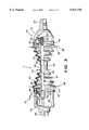
- FIG. 3is a enlarged side elevational view of the half shaft assembly shown in FIG. 2 with portions sectioned.
- FIG. 4is a partial enlarged sectional view of an alternate embodiment of a half shaft assembly according to the present invention.
- FIG. 5is a view similar to FIG. 4 of another embodiment of a half shaft assembly acceding to the present invention.
- FIG. 6is a view similar to FIG. 4 of yet another embodiment of a half shaft assembly according to the present invention.
- an automotive vehicle 10has a rigid frame or chassis 12.
- the chassis 12is supported on a pair of rear wheels 14 and front wheels 16.
- Juxtaposed between the chassis 12 and each of the rear and front wheels 14, 16is a suspension system (not shown).
- the suspension systemallows the rear and front wheels 14, 16 to follow the contour of a road surface. Therefore the front and rear wheels 14, 16 can have relative movement with respect to the chassis 12.
- the vehicle 10can also has a steering system (not shown) to turn the front wheels 16.
- An engine 18is provided to power the vehicle 10.
- the engine 18is positioned transverse to a major axis 20 of the vehicle 10, although the engine could be axially oriented as well.
- the engine 18is mounted rigidly to the chassis 12.
- the engine 18transfers torque to a transmission 22.
- the transmission 22is also rigidly mounted to the chassis 12.
- the transmission 22transfers torque to the front wheels 16.
- the half shaft assembly 7includes a half shaft 24, as shown in FIG. 3.
- the half shaft 24is formed from a solid stock of metal.
- An inboard end 26 of the half shaftis pivotally rotatively coupled with an output shaft 28 of the transmission.
- the above noted pivotal couplingis accomplished by an inboard constant velocity universal joint 30.
- An outboard end 27 of the half shaftis pivotally rotatively coupled with a wheel axle 32.
- the half shaft to wheel axle pivotal couplingis accomplished by an outboard constant velocity universal joint 34.
- the half shaft inboard end 26has secured thereto a constant velocity universal joint inner race 36.
- the inner race 36 along an outer surface 38has a series of geometrically spaced linear grooves 40.
- the grooves 40have a semi-circular or other similar cross-sectional shape with a linear axis that is alternately inclined with respect to a major axis of the half shaft 24.
- a constant velocity universal joint cage 42 and series of geometrically spaced balls 44form a cage and ball assembly.
- the cage 42 and balls 44encircle the inner race 36.
- the cage 42retains the balls 44 in the their respective grooves 40.
- Encircling the cage 42 and balls 44is an inboard constant velocity universal joint outer race 46.
- the outer race 46is typically formed integrally with the transmission output shaft 28, or at least rigidly connected for rotation with the transmission output shaft 28.
- the outer race 46has a series of geometrically spaced linear grooves 48 corresponding with the grooves 40 in the surface of the inner race 36.
- the grooves 48have a semi-circular or other similar cross-sectional shape with a linear axis.
- the grooves 48are alternately or cross inclined with respect to the grooves 40.
- One of the balls 44is disposed in each one of the paired grooves 40, 48.
- the balls 44provide a torsional association or driving connection between the outer race 46 and the inner race 36 while allowing the transmission output shaft 28 and the half shaft 24 to rotate on non-collinear axes.
- the half shaft outboard end 27has secured thereto a constant velocity universal joint inner race 60.
- the inner race 60 along a curvilinear outer surface 62has a series of geometrically spaced curvilinear grooves 64.
- the grooves 64have a semi-circular or other similar cross-sectional shape with a curvilinear axis that is inclined with respect to a major axis of the half shaft 24.
- a constant velocity universal joint cage 66 and series of geometrically spaced balls 68form a cage and ball assembly.
- the cage 66 and balls 68encircle the inner race 60.
- the cage 66retains the balls 68 in the their respective grooves 64.
- Encircling the cage 66 and ball 68 assemblyis an inboard constant velocity universal joint outer race 70.
- the outer race 70is typically formed integrally with the is wheel axle 32.
- the outer race 70has a series of geometrically spaced curvilinear grooves 72 to associate with the grooves 64.
- the grooves 72have a semi-circular or other similar cross-sectional shape with a curvilinear axis.
- the grooves 72are alternately or cross inclined with respect to the grooves 40.
- One of the balls 68is disposed in each one of the paired grooves 64, 72.
- the balls 68provide a torsional association or driving connection between the outer race 60 and the inner race 70 while allowing the transmission output shaft 28 and the half shaft 24 to rotate on non-collinear axes.
- the half shaft assembly 7has a protective boot 80.
- the boot 80is fabricated from an elastomeric material.
- the boot 80has a semi-hyperbolic shape with a convergent center 82 and divergent inboard and outboard ends 84, 86, although other shapes can be used.
- An outer diameter 87 of the center 82is significantly smaller than the outer diameter 88 of the inboard divergent end 84 or the outer diameter 89 of the outboard divergent end 86.
- the boot 80has convolutions 90 to allow for bending motion of the constant velocity universal joints 30, 34.
- the largest outer diameter 88 or 89 at either end of the boot 80is larger than the diameter 87 of the boot at the center of the boot by a ratio of at least 3:1. In some cases this ratio is at least 6:1.
- an inner diameter 92 of the convergent center 82is sized to fit snugly around the half shaft 24 to prevent relative movement of the boot 80 with respect to the half shaft 24.
- the clearance between the boot and the shaftis no more than about 0.020 inches, and most preferably no more than about 0.010 inches.
- the outer and inner diameters 87, 92 of the convergent centerextend a relatively short distance forming a flat section 94 having generally flat or constant inner and outer diameters.
- the inboard divergent end 84is secured to the outer race 46 by a clamp 96.
- the outboard divergent end 86is secured to the outer race 70 by a clamp 98.
- the bootwill rotate in unison with the output shaft 28, the half shaft 24, and the wheel axle 32.
- the effect of using the unified boot 80 in place of two separate boots, not shown,is that only two clamps are required for the entire boot assembly, and no clamp is needed at the center of the half shaft. This is advantageous because it saves assembly labor and material cost.
- a single clampcan be placed around the convergent center 82 to secure the convergent center to the half shaft.
- One of the primary benefits of the half shaft assembly of the inventionis that there is no longer an exposed center portion of the half shaft subject to rust and corrosion. Therefore, the half shaft need not be painted or otherwise treated for resistance to the elements. The entire half shaft is protected by the boot, whereas the prior art half shaft assemblies had spaced apart boots.
- the half shaft assembly 107is substantially similar to the half shaft assembly 7 with some notable modifications.
- the half shaft assembly 107has a half shaft 124, having a diameter 125.
- the half shafthas an annular groove 126 with a diameter 127 that is less than the diameter 125 of the half shaft.
- a protective boot 128has a convergent center portion 129.
- an inward facing circumferential or annular ridge 132is positioned. This ridge has a diameter smaller than the diameter 125 of the half shaft.
- the annular ridgeis sized to fit snugly within and around the annular groove 126.
- the circumferential ridge 132may have radial and axial interference with the annular groove 126.
- the advantage of the cooperating annular groove 126 and the annular ridge 128is that the boot is restricted from moving axially with respect to the half shaft 124, and yet in many if not all applications, the snug fit of the boot's convergent center around the half shaft will delete any requirement of clamp attachment of the boot to the half shaft. Therefore, in most embodiments the inventive half shaft assembly will only require two end clamps for securing the boot to the outer races.
- FIG. 4An additional benefit of the invention shown in FIG. 4 is that as the boot 128 is being moved or slid along the half shaft during assembly, the mating of the annular ridge 132 and the annular groove 126 will enable the installer to know that the boot has been moved into the desired axial location on the half shaft.
- the cooperating annular ridge 132 and the annular groove 126act as a general indicator for the installer as to whether or not the boot has reached the axial location desired for proper assembly.
- half shaft assembly 207is substantially similar to the half shaft assembly 107 shown in FIG. 4, with the difference being that fact that the half shaft 224 is provided with an annular ridge 226 rather than an annular groove.
- a protective boot 228has a convergent center portion 229. Along an inner diameter 230 of the convergent center portion, an inward facing circumferential or annular groove 232 is positioned. The annular ridge 226 is sized to fit snugly within and around the annular groove 226.
- half shaft assembly 307is similar to the half shaft assembly 107 shown in FIG. 4, but with the half shaft 314 having a first end 316 with a diameter substantially smaller than the diameter of the second end 318.
- the difference in diameters of the first and second ends of the half shaft 314creates an annular shoulder 320.
- the boot 328has a convergent center portion 329.
- the convergent center portiondefmes two distinct inner diameters, a larger inner diameter 331 and a smaller inner diameter 330, thereby defining a step 332.
- the step 332acts with the annular shoulder 320 to form a positive indication that boot 328 and the half shaft 314 are in a predetermined axial location with respect to each other.
- the boot 328will be stopped in a defined axial relationship with respect to the half shaft when the boot step 332 meets the half shaft annular shoulder 320.
Landscapes
- Engineering & Computer Science (AREA)
- General Engineering & Computer Science (AREA)
- Mechanical Engineering (AREA)
- Joints Allowing Movement (AREA)
- Sealing Devices (AREA)
- Shafts, Cranks, Connecting Bars, And Related Bearings (AREA)
Abstract
Description
Claims (10)
Priority Applications (2)
| Application Number | Priority Date | Filing Date | Title |
|---|---|---|---|
| US08/955,055US5931738A (en) | 1997-10-21 | 1997-10-21 | Universal joint assembly protected by a boot |
| BR9807861-5ABR9807861A (en) | 1997-10-21 | 1998-10-21 | Universal joint assembly protected by a housing |
Applications Claiming Priority (1)
| Application Number | Priority Date | Filing Date | Title |
|---|---|---|---|
| US08/955,055US5931738A (en) | 1997-10-21 | 1997-10-21 | Universal joint assembly protected by a boot |
Publications (1)
| Publication Number | Publication Date |
|---|---|
| US5931738Atrue US5931738A (en) | 1999-08-03 |
Family
ID=25496315
Family Applications (1)
| Application Number | Title | Priority Date | Filing Date |
|---|---|---|---|
| US08/955,055Expired - LifetimeUS5931738A (en) | 1997-10-21 | 1997-10-21 | Universal joint assembly protected by a boot |
Country Status (2)
| Country | Link |
|---|---|
| US (1) | US5931738A (en) |
| BR (1) | BR9807861A (en) |
Cited By (16)
| Publication number | Priority date | Publication date | Assignee | Title |
|---|---|---|---|---|
| US6634951B2 (en)* | 1999-12-15 | 2003-10-21 | Ntn Corporation | Driving wheel bearing unit |
| US20030236122A1 (en)* | 2002-06-24 | 2003-12-25 | Gkn Automotive, Inc. | Propeller shaft assembly |
| US6682429B2 (en) | 2002-06-13 | 2004-01-27 | Visteon Global Technologies, Inc. | Shaft with a venting system |
| US6722991B2 (en) | 2001-03-15 | 2004-04-20 | Visteon Global Technologies, Inc. | Venting system and method for a driveshaft |
| US6739976B2 (en) | 2001-03-15 | 2004-05-25 | Visteon Global Technologies, Inc. | Plastic boot for sealing double-tube driveshaft |
| US6802780B2 (en) | 2001-03-15 | 2004-10-12 | Visteon Global Technologies, Inc. | Seal for double-tube driveshaft |
| FR2862731A1 (en)* | 2003-11-26 | 2005-05-27 | Koyo Steering Europe Kse | Rack and pinion steering gears boot for motor vehicle, has two deformable parts, one extending around one end of steering rack external to steering gear box, and other extending from one side of tie rod on which it is fixed |
| US20050215330A1 (en)* | 2004-03-29 | 2005-09-29 | Pauline Maria Foster-Hamilton | Boot with articulating and plunging convolutes |
| US20080042388A1 (en)* | 2006-08-15 | 2008-02-21 | Ride The Ducks International, Llc | Steering Knuckle Boot |
| EP1970586A4 (en)* | 2005-12-22 | 2010-05-26 | Ntn Toyo Bearing Co Ltd | Joint assembly and vehicle-use bearing unit, and axle module provided with them |
| US20100225088A1 (en)* | 2007-03-05 | 2010-09-09 | Wernli Bradley E | Three-wheeled rear-steering scooter |
| WO2012078474A1 (en)* | 2010-12-09 | 2012-06-14 | B.E.W. Squared, Llc | Skate truck |
| US8469377B2 (en) | 2009-06-25 | 2013-06-25 | Sbyke Usa Llc | Truck assembly |
| US8602422B2 (en) | 2010-12-09 | 2013-12-10 | Sbyke Usa Llc | Three wheeled scooter with rear skate truck and fixed front wheel |
| US20140033855A1 (en)* | 2012-08-01 | 2014-02-06 | GM Global Technology Operations LLC | Seal assembly |
| US8827296B2 (en) | 2007-03-05 | 2014-09-09 | Sbyke Usa Llc | Three-wheeled rear-steering scooter |
Citations (21)
| Publication number | Priority date | Publication date | Assignee | Title |
|---|---|---|---|---|
| US34341A (en)* | 1862-02-04 | 1862-02-04 | Improvement in calendar-clocks | |
| US2451791A (en)* | 1945-01-25 | 1948-10-19 | Towmotor Corp | Universal joint |
| US2702996A (en)* | 1954-08-31 | 1955-03-01 | Davis C Edward | Bell housing cover |
| GB799402A (en)* | 1955-11-02 | 1958-08-06 | Atkinsons Agricultural Appl | Improvements in or relating to machinery guards |
| US3747368A (en)* | 1970-09-11 | 1973-07-24 | Dba Sa | Double universal joint |
| US3962889A (en)* | 1974-07-11 | 1976-06-15 | Kenneth G. Fraser | Lubricated joint assembly |
| DE2804339A1 (en)* | 1977-02-14 | 1978-08-17 | Citroen Sa | PROTECTIVE SEAL FOR JOINT CONNECTIONS OF MOTOR VEHICLE SHAFTS |
| US4360209A (en)* | 1980-03-11 | 1982-11-23 | Toyoda Gosei Co., Ltd. | Universal joint dust boot assembly |
| US4556400A (en)* | 1981-08-05 | 1985-12-03 | Uni-Cardan Aktiengesellschaft | Drive shaft assembly for motor vehicles |
| US4664393A (en)* | 1985-02-15 | 1987-05-12 | Gkn Automotive Components Inc. | Sliding-segment boot for plunging mechanical joint |
| JPS62288727A (en)* | 1986-06-05 | 1987-12-15 | Yamaha Motor Co Ltd | Cover device for transmission shaft device |
| US4805921A (en)* | 1987-03-04 | 1989-02-21 | Toyoda Gosei Co., Ltd. | Mechanical shaft joint boot |
| US4820238A (en)* | 1987-02-27 | 1989-04-11 | Keeper Co., Ltd. | Universal joint having a flexible boot |
| US4877258A (en)* | 1986-12-04 | 1989-10-31 | Daimler-Benz Aktiengesellschaft | Fold bellows for rotating vehicle drive joint |
| US4927678A (en)* | 1987-12-01 | 1990-05-22 | Compagnie Des Products Industriels de l'Ouest (C.P.I.O.) | Protective bellows particularly for a motor vehicle front wheel drive |
| JPH02225826A (en)* | 1990-01-25 | 1990-09-07 | Kiipaa Kk | Method for sealing lubricating in inner space of flexible boot in uniform joint device |
| GB2238844A (en)* | 1989-12-07 | 1991-06-12 | Draftex Ind Ltd | Protection bellows for transmission shaft. |
| US5052979A (en)* | 1984-08-16 | 1991-10-01 | Lohr & Bromkamp Gmbh | Shaft assembly for the wheel drive of a motor vehicle |
| USRE34341E (en) | 1989-08-28 | 1993-08-10 | Ntn Corporation | Structure for mounting boot |
| US5312300A (en)* | 1992-09-02 | 1994-05-17 | General Motors Corporation | Protective cover for universal joint seal boot |
| US5692962A (en)* | 1994-04-12 | 1997-12-02 | Ntn Corporation | Attaching construction of a resin boot to a mating member |
- 1997
- 1997-10-21USUS08/955,055patent/US5931738A/ennot_activeExpired - Lifetime
- 1998
- 1998-10-21BRBR9807861-5Apatent/BR9807861A/ennot_activeIP Right Cessation
Patent Citations (21)
| Publication number | Priority date | Publication date | Assignee | Title |
|---|---|---|---|---|
| US34341A (en)* | 1862-02-04 | 1862-02-04 | Improvement in calendar-clocks | |
| US2451791A (en)* | 1945-01-25 | 1948-10-19 | Towmotor Corp | Universal joint |
| US2702996A (en)* | 1954-08-31 | 1955-03-01 | Davis C Edward | Bell housing cover |
| GB799402A (en)* | 1955-11-02 | 1958-08-06 | Atkinsons Agricultural Appl | Improvements in or relating to machinery guards |
| US3747368A (en)* | 1970-09-11 | 1973-07-24 | Dba Sa | Double universal joint |
| US3962889A (en)* | 1974-07-11 | 1976-06-15 | Kenneth G. Fraser | Lubricated joint assembly |
| DE2804339A1 (en)* | 1977-02-14 | 1978-08-17 | Citroen Sa | PROTECTIVE SEAL FOR JOINT CONNECTIONS OF MOTOR VEHICLE SHAFTS |
| US4360209A (en)* | 1980-03-11 | 1982-11-23 | Toyoda Gosei Co., Ltd. | Universal joint dust boot assembly |
| US4556400A (en)* | 1981-08-05 | 1985-12-03 | Uni-Cardan Aktiengesellschaft | Drive shaft assembly for motor vehicles |
| US5052979A (en)* | 1984-08-16 | 1991-10-01 | Lohr & Bromkamp Gmbh | Shaft assembly for the wheel drive of a motor vehicle |
| US4664393A (en)* | 1985-02-15 | 1987-05-12 | Gkn Automotive Components Inc. | Sliding-segment boot for plunging mechanical joint |
| JPS62288727A (en)* | 1986-06-05 | 1987-12-15 | Yamaha Motor Co Ltd | Cover device for transmission shaft device |
| US4877258A (en)* | 1986-12-04 | 1989-10-31 | Daimler-Benz Aktiengesellschaft | Fold bellows for rotating vehicle drive joint |
| US4820238A (en)* | 1987-02-27 | 1989-04-11 | Keeper Co., Ltd. | Universal joint having a flexible boot |
| US4805921A (en)* | 1987-03-04 | 1989-02-21 | Toyoda Gosei Co., Ltd. | Mechanical shaft joint boot |
| US4927678A (en)* | 1987-12-01 | 1990-05-22 | Compagnie Des Products Industriels de l'Ouest (C.P.I.O.) | Protective bellows particularly for a motor vehicle front wheel drive |
| USRE34341E (en) | 1989-08-28 | 1993-08-10 | Ntn Corporation | Structure for mounting boot |
| GB2238844A (en)* | 1989-12-07 | 1991-06-12 | Draftex Ind Ltd | Protection bellows for transmission shaft. |
| JPH02225826A (en)* | 1990-01-25 | 1990-09-07 | Kiipaa Kk | Method for sealing lubricating in inner space of flexible boot in uniform joint device |
| US5312300A (en)* | 1992-09-02 | 1994-05-17 | General Motors Corporation | Protective cover for universal joint seal boot |
| US5692962A (en)* | 1994-04-12 | 1997-12-02 | Ntn Corporation | Attaching construction of a resin boot to a mating member |
Cited By (32)
| Publication number | Priority date | Publication date | Assignee | Title |
|---|---|---|---|---|
| US6634951B2 (en)* | 1999-12-15 | 2003-10-21 | Ntn Corporation | Driving wheel bearing unit |
| US6722991B2 (en) | 2001-03-15 | 2004-04-20 | Visteon Global Technologies, Inc. | Venting system and method for a driveshaft |
| US6739976B2 (en) | 2001-03-15 | 2004-05-25 | Visteon Global Technologies, Inc. | Plastic boot for sealing double-tube driveshaft |
| US6802780B2 (en) | 2001-03-15 | 2004-10-12 | Visteon Global Technologies, Inc. | Seal for double-tube driveshaft |
| US6682429B2 (en) | 2002-06-13 | 2004-01-27 | Visteon Global Technologies, Inc. | Shaft with a venting system |
| US20030236122A1 (en)* | 2002-06-24 | 2003-12-25 | Gkn Automotive, Inc. | Propeller shaft assembly |
| FR2862731A1 (en)* | 2003-11-26 | 2005-05-27 | Koyo Steering Europe Kse | Rack and pinion steering gears boot for motor vehicle, has two deformable parts, one extending around one end of steering rack external to steering gear box, and other extending from one side of tie rod on which it is fixed |
| US20050215330A1 (en)* | 2004-03-29 | 2005-09-29 | Pauline Maria Foster-Hamilton | Boot with articulating and plunging convolutes |
| US7281984B2 (en)* | 2004-03-29 | 2007-10-16 | Gkn Driveline North America, Inc., | Boot with articulating and plunging convolutes |
| EP1970586A4 (en)* | 2005-12-22 | 2010-05-26 | Ntn Toyo Bearing Co Ltd | Joint assembly and vehicle-use bearing unit, and axle module provided with them |
| US20080042388A1 (en)* | 2006-08-15 | 2008-02-21 | Ride The Ducks International, Llc | Steering Knuckle Boot |
| US8011077B2 (en) | 2006-08-15 | 2011-09-06 | Ride The Ducks International, Llc | Steering knuckle boot |
| US20100223774A1 (en)* | 2006-08-15 | 2010-09-09 | Ride The Ducks International, Llc | Steering knuckle boot |
| US7793953B2 (en)* | 2006-08-15 | 2010-09-14 | Ride The Ducks International, Llc | Steering knuckle boot |
| US8336894B2 (en) | 2007-03-05 | 2012-12-25 | B.E.W. Squared, Llc | Three-wheeled rear-steering scooter |
| US9296443B2 (en) | 2007-03-05 | 2016-03-29 | Sbyke Usa Llc | Three-wheeled rear-steering scooter |
| US20100225088A1 (en)* | 2007-03-05 | 2010-09-09 | Wernli Bradley E | Three-wheeled rear-steering scooter |
| US10300976B2 (en) | 2007-03-05 | 2019-05-28 | Sbyke Usa Llc | Three-wheeled rear-steering scooter |
| US9937974B2 (en) | 2007-03-05 | 2018-04-10 | Sbyke Usa Llc | Three-wheeled rear-steering scooter |
| US9533728B2 (en) | 2007-03-05 | 2017-01-03 | Sbyke Usa Llc | Three-wheeled rear-steering scooter |
| US8998226B2 (en) | 2007-03-05 | 2015-04-07 | Sbyke Usa Llc | Three-wheeled rear-steering scooter |
| US8827296B2 (en) | 2007-03-05 | 2014-09-09 | Sbyke Usa Llc | Three-wheeled rear-steering scooter |
| US8469377B2 (en) | 2009-06-25 | 2013-06-25 | Sbyke Usa Llc | Truck assembly |
| US8801008B2 (en) | 2010-12-09 | 2014-08-12 | Sbyke Usa Llc | Three wheeled scooter with rear skate truck and fixed front wheel |
| US8602422B2 (en) | 2010-12-09 | 2013-12-10 | Sbyke Usa Llc | Three wheeled scooter with rear skate truck and fixed front wheel |
| CN103402591B (en)* | 2010-12-09 | 2015-07-01 | B.E.W.方有限责任公司 | Skid rail bogie |
| WO2012078474A1 (en)* | 2010-12-09 | 2012-06-14 | B.E.W. Squared, Llc | Skate truck |
| AU2011338715B2 (en)* | 2010-12-09 | 2016-10-06 | B.E.W. Squared, Llc | A suspension for a vehicle |
| CN103402591A (en)* | 2010-12-09 | 2013-11-20 | B.E.W.方有限责任公司 | Skate truck |
| US8448954B2 (en) | 2010-12-09 | 2013-05-28 | Sbyke Usa Llc | Skate truck |
| US20140033855A1 (en)* | 2012-08-01 | 2014-02-06 | GM Global Technology Operations LLC | Seal assembly |
| US9108671B2 (en)* | 2012-08-01 | 2015-08-18 | GM Global Technology Operations LLC | Seal assembly |
Also Published As
| Publication number | Publication date |
|---|---|
| BR9807861A (en) | 2000-08-29 |
Similar Documents
| Publication | Publication Date | Title |
|---|---|---|
| US5931738A (en) | Universal joint assembly protected by a boot | |
| US4405032A (en) | Wheel hub assembly | |
| CA1223448A (en) | Drive shaft, especially for driving the wheels of a motor vehicle | |
| US7896749B2 (en) | Direct torque flow connection with optimized ratios in attachment methods | |
| US5433667A (en) | Centered double cardan joint for steering shafts in motor vehicles | |
| US7347785B2 (en) | Propshaft with constant velocity joint attachment | |
| US5525112A (en) | Combined seal and boot for steering shaft assembly | |
| GB2171173A (en) | Boot for universal joint | |
| US7553238B2 (en) | Connecting assembly between a shaft journal and a constant velocity universal joint | |
| US7534048B2 (en) | Center bearing assembly for rotatably supporting a shaft at varying angles relative to a support surface | |
| US7534172B2 (en) | Direct torque flow constant velocity joint having a non-rotating boot | |
| CA1336288C (en) | Multi-component, multi-segment, non-flexible boot for mechanical joint | |
| US5899814A (en) | Vehicle drive train incorporating a plunging constant velocity joint | |
| GB2122959A (en) | Transmission for a motor vehicle | |
| KR20030085092A (en) | Wheel drive unit | |
| US20020068638A1 (en) | Sealing assembly for constant velocity joint | |
| US5494129A (en) | Insertable unit for a bearing assembly | |
| KR100501850B1 (en) | Hub unit | |
| US4605384A (en) | Self-aligning tripod joint tulip cover and constant velocity joint incorporating same | |
| US6976922B2 (en) | Precision thrust bearing joint | |
| US5643091A (en) | Stroking constant velocity universal joint having low stroke load | |
| US2845782A (en) | Ball bearing spline | |
| US4807939A (en) | Joint structure for axle | |
| US4255943A (en) | Holding structure for a drive shaft in a vehicle of rear wheel independent suspension type | |
| US6558262B1 (en) | Boot for slip yoke assembly in a vehicle driveshaft |
Legal Events
| Date | Code | Title | Description |
|---|---|---|---|
| AS | Assignment | Owner name:DANA CORPORATION, OHIO Free format text:ASSIGNMENT OF ASSIGNORS INTEREST;ASSIGNOR:ROBB, SCOTT B.;REEL/FRAME:008860/0774 Effective date:19971020 | |
| FEPP | Fee payment procedure | Free format text:PAYOR NUMBER ASSIGNED (ORIGINAL EVENT CODE: ASPN); ENTITY STATUS OF PATENT OWNER: LARGE ENTITY | |
| STCF | Information on status: patent grant | Free format text:PATENTED CASE | |
| AS | Assignment | Owner name:SPICER DRIVESHAFT, INC., OHIO Free format text:ASSIGNMENT OF ASSIGNORS INTEREST;ASSIGNOR:DANA CORPORATION, A VIRGINIA CORPORATION;REEL/FRAME:011667/0621 Effective date:20001221 | |
| FPAY | Fee payment | Year of fee payment:4 | |
| AS | Assignment | Owner name:TORQUE-TRACTION TECHNOLOGIES, INC., OHIO Free format text:CHANGE OF NAME;ASSIGNOR:SPICER DRIVESHAFT, INC.;REEL/FRAME:013933/0631 Effective date:20021231 | |
| AS | Assignment | Owner name:TORQUE-TRACTION TECHNOLOGIES LLC,OHIO Free format text:MERGER;ASSIGNOR:TORQUE-TRACTION TECHNOLOGY, INC.;REEL/FRAME:017240/0259 Effective date:20060101 Owner name:TORQUE-TRACTION TECHNOLOGIES LLC, OHIO Free format text:MERGER;ASSIGNOR:TORQUE-TRACTION TECHNOLOGY, INC.;REEL/FRAME:017240/0259 Effective date:20060101 | |
| FPAY | Fee payment | Year of fee payment:8 | |
| AS | Assignment | Owner name:DANA AUTOMOTIVE SYSTEMS GROUP, LLC, OHIO Free format text:ASSIGNMENT OF ASSIGNORS INTEREST;ASSIGNOR:TORQUE-TRACTION TECHNOLOGIES, LLC;REEL/FRAME:020518/0949 Effective date:20080131 Owner name:DANA AUTOMOTIVE SYSTEMS GROUP, LLC,OHIO Free format text:ASSIGNMENT OF ASSIGNORS INTEREST;ASSIGNOR:TORQUE-TRACTION TECHNOLOGIES, LLC;REEL/FRAME:020518/0949 Effective date:20080131 | |
| AS | Assignment | Owner name:CITICORP USA, INC., NEW YORK Free format text:INTELLECTUAL PROPERTY REVOLVING FACILITY SECURITY AGREEMENT;ASSIGNORS:DANA HOLDING CORPORATION;DANA LIMITED;DANA AUTOMOTIVE SYSTEMS GROUP, LLC;AND OTHERS;REEL/FRAME:020859/0249 Effective date:20080131 Owner name:CITICORP USA, INC.,NEW YORK Free format text:INTELLECTUAL PROPERTY REVOLVING FACILITY SECURITY AGREEMENT;ASSIGNORS:DANA HOLDING CORPORATION;DANA LIMITED;DANA AUTOMOTIVE SYSTEMS GROUP, LLC;AND OTHERS;REEL/FRAME:020859/0249 Effective date:20080131 Owner name:CITICORP USA, INC., NEW YORK Free format text:INTELLECTUAL PROPERTY TERM FACILITY SECURITY AGREEMENT;ASSIGNORS:DANA HOLDING CORPORATION;DANA LIMITED;DANA AUTOMOTIVE SYSTEMS GROUP, LLC;AND OTHERS;REEL/FRAME:020859/0359 Effective date:20080131 Owner name:CITICORP USA, INC.,NEW YORK Free format text:INTELLECTUAL PROPERTY TERM FACILITY SECURITY AGREEMENT;ASSIGNORS:DANA HOLDING CORPORATION;DANA LIMITED;DANA AUTOMOTIVE SYSTEMS GROUP, LLC;AND OTHERS;REEL/FRAME:020859/0359 Effective date:20080131 | |
| FPAY | Fee payment | Year of fee payment:12 |