US5930682A - Centralized channel selection in a distributed RF antenna system - Google Patents
Centralized channel selection in a distributed RF antenna systemDownload PDFInfo
- Publication number
- US5930682A US5930682AUS08/864,298US86429897AUS5930682AUS 5930682 AUS5930682 AUS 5930682AUS 86429897 AUS86429897 AUS 86429897AUS 5930682 AUS5930682 AUS 5930682A
- Authority
- US
- United States
- Prior art keywords
- signal
- frequency
- remote
- central
- communication
- Prior art date
- Legal status (The legal status is an assumption and is not a legal conclusion. Google has not performed a legal analysis and makes no representation as to the accuracy of the status listed.)
- Expired - Lifetime
Links
Images

Classifications
- H—ELECTRICITY
- H04—ELECTRIC COMMUNICATION TECHNIQUE
- H04B—TRANSMISSION
- H04B1/00—Details of transmission systems, not covered by a single one of groups H04B3/00 - H04B13/00; Details of transmission systems not characterised by the medium used for transmission
- H04B1/0003—Software-defined radio [SDR] systems, i.e. systems wherein components typically implemented in hardware, e.g. filters or modulators/demodulators, are implented using software, e.g. by involving an AD or DA conversion stage such that at least part of the signal processing is performed in the digital domain
- H04B1/0007—Software-defined radio [SDR] systems, i.e. systems wherein components typically implemented in hardware, e.g. filters or modulators/demodulators, are implented using software, e.g. by involving an AD or DA conversion stage such that at least part of the signal processing is performed in the digital domain wherein the AD/DA conversion occurs at radiofrequency or intermediate frequency stage
- H—ELECTRICITY
- H03—ELECTRONIC CIRCUITRY
- H03D—DEMODULATION OR TRANSFERENCE OF MODULATION FROM ONE CARRIER TO ANOTHER
- H03D7/00—Transference of modulation from one carrier to another, e.g. frequency-changing
- H03D7/16—Multiple-frequency-changing
- H03D7/161—Multiple-frequency-changing all the frequency changers being connected in cascade
- H03D7/163—Multiple-frequency-changing all the frequency changers being connected in cascade the local oscillations of at least two of the frequency changers being derived from a single oscillator
- H—ELECTRICITY
- H03—ELECTRONIC CIRCUITRY
- H03L—AUTOMATIC CONTROL, STARTING, SYNCHRONISATION OR STABILISATION OF GENERATORS OF ELECTRONIC OSCILLATIONS OR PULSES
- H03L7/00—Automatic control of frequency or phase; Synchronisation
- H03L7/06—Automatic control of frequency or phase; Synchronisation using a reference signal applied to a frequency- or phase-locked loop
- H03L7/07—Automatic control of frequency or phase; Synchronisation using a reference signal applied to a frequency- or phase-locked loop using several loops, e.g. for redundant clock signal generation
- H—ELECTRICITY
- H03—ELECTRONIC CIRCUITRY
- H03L—AUTOMATIC CONTROL, STARTING, SYNCHRONISATION OR STABILISATION OF GENERATORS OF ELECTRONIC OSCILLATIONS OR PULSES
- H03L7/00—Automatic control of frequency or phase; Synchronisation
- H03L7/06—Automatic control of frequency or phase; Synchronisation using a reference signal applied to a frequency- or phase-locked loop
- H03L7/16—Indirect frequency synthesis, i.e. generating a desired one of a number of predetermined frequencies using a frequency- or phase-locked loop
- H03L7/22—Indirect frequency synthesis, i.e. generating a desired one of a number of predetermined frequencies using a frequency- or phase-locked loop using more than one loop
- H03L7/23—Indirect frequency synthesis, i.e. generating a desired one of a number of predetermined frequencies using a frequency- or phase-locked loop using more than one loop with pulse counters or frequency dividers
- H—ELECTRICITY
- H04—ELECTRIC COMMUNICATION TECHNIQUE
- H04B—TRANSMISSION
- H04B1/00—Details of transmission systems, not covered by a single one of groups H04B3/00 - H04B13/00; Details of transmission systems not characterised by the medium used for transmission
- H04B1/0003—Software-defined radio [SDR] systems, i.e. systems wherein components typically implemented in hardware, e.g. filters or modulators/demodulators, are implented using software, e.g. by involving an AD or DA conversion stage such that at least part of the signal processing is performed in the digital domain
- H—ELECTRICITY
- H04—ELECTRIC COMMUNICATION TECHNIQUE
- H04B—TRANSMISSION
- H04B1/00—Details of transmission systems, not covered by a single one of groups H04B3/00 - H04B13/00; Details of transmission systems not characterised by the medium used for transmission
- H04B1/06—Receivers
- H04B1/16—Circuits
- H04B1/26—Circuits for superheterodyne receivers
- H—ELECTRICITY
- H04—ELECTRIC COMMUNICATION TECHNIQUE
- H04B—TRANSMISSION
- H04B3/00—Line transmission systems
- H—ELECTRICITY
- H04—ELECTRIC COMMUNICATION TECHNIQUE
- H04B—TRANSMISSION
- H04B7/00—Radio transmission systems, i.e. using radiation field
- H04B7/24—Radio transmission systems, i.e. using radiation field for communication between two or more posts
- H04B7/26—Radio transmission systems, i.e. using radiation field for communication between two or more posts at least one of which is mobile
- H04B7/2603—Arrangements for wireless physical layer control
- H04B7/2609—Arrangements for range control, e.g. by using remote antennas
- H—ELECTRICITY
- H03—ELECTRONIC CIRCUITRY
- H03D—DEMODULATION OR TRANSFERENCE OF MODULATION FROM ONE CARRIER TO ANOTHER
- H03D7/00—Transference of modulation from one carrier to another, e.g. frequency-changing
- H—ELECTRICITY
- H04—ELECTRIC COMMUNICATION TECHNIQUE
- H04W—WIRELESS COMMUNICATION NETWORKS
- H04W84/00—Network topologies
- H04W84/02—Hierarchically pre-organised networks, e.g. paging networks, cellular networks, WLAN [Wireless Local Area Network] or WLL [Wireless Local Loop]
- H04W84/10—Small scale networks; Flat hierarchical networks
- H04W84/14—WLL [Wireless Local Loop]; RLL [Radio Local Loop]
Definitions
- This inventionrelates to the field of wireless communications, and in particular to a radio-frequency distribution system with centralized tunable channel selection.
- In-building distribution systemsconsist of two major parts: a set of repeater antennas and accessories required for re-transmitting RF signals inside buildings, and a cabling system such as an optical fiber network for interconnecting the in-building antennas with a main antenna.
- the main antennais usually installed on top of the building, while the repeaters are located within various rooms inside the building.
- the cost of installing in-building distribution networksis generally very high, and includes the cost of multiple repeater antennas, associated electronics, and links, as well as the cost of installing the antennas and suitable links. It is desirable that the signal processing electronics used at the repeater sites be simple, robust, and inexpensive. It is also desirable that the signals distributed through the network be compatible with pre-existing in-building wiring infrastructure, since installing specialized links can be prohibitively expensive.
- Kallander et al.describe a repeater system for use in complex environments.
- the systemcomprises two-way frequency converters for down-converting a centrally received high-frequency signal, and recovering the signal at remote locations by up-conversion.
- the system described by Kallander et al.re-transmits the entire frequency band of the received signal.
- Yet another object of the inventionis to provide an in-building high-frequency distribution system using low-stability, low-cost remote oscillators that are frequency-stabilized using a single central high-stability oscillator.
- the notation ⁇ A j! ⁇is understood to refer to a set of A j! for j between 1 and a maximum value J.
- the index jis generally used to refer to all channels received by a system of the present invention
- the index kis generally used to refer to channels selected for emission by a system of the present invention.
- a quantity if fixedis understood to mean that the quantity is independent of which channel(s) is/are selected for emission by a system of the present invention.
- the present inventionprovides a distributed wireless communications system with centralized tunable channel selection.
- the central receiving meanspreferably comprises a receiver antenna for wireless communications.
- the central high-frequency signalis preferably within a frequency band used for cellular communications, cordless telephony, personal communication services, local radio-frequency communications, satellite television, interactive multi-media video, or high bit-rate local area networks.
- the central channel selection meanscomprises a central mixing means in communication with the central receiving means, and a central reference means in communication with the central mixing means.
- the central mixing meansgenerates an intermediate signal from the central high-frequency signal and a central reference signal.
- the intermediate signalcomprises a channel C' k! corresponding to the channel C k!.
- the channel C' k!encodes the information contained in channel C k!, but is centered at a different (preferably lower) frequency than channel C k!.
- the central reference meansgenerates the central reference signal, and controls the frequency of the central reference signal such that the channel C' k! is suitable for transmission through a filtering means of a fixed bandwidth. Channels other than C' k! are filtered out by the filtering means.
- a digitization means in communication with the filtering meansdigitizes the intermediate signal after passage through the filtering means.
- Channel C k!preferably comprises a plurality of code-division-multiple-access (CDMA) carriers, such that channel C k! is capable of supporting multiple users.
- CDMAcode-division-multiple-access
- Limiting the bandwidth of the signal selected for emissionis advantageous because it allows an increase in the power of the emitted signal. Such an increase in power for a signal of a broad bandwidth would lead to distortions at signal processing elements such as amplifiers and mixers. Furthermore, limiting the transmitted intermediate signal to a single channel greatly facilitates its digitization if analog to digital conversion is to be performed.
- a plurality of remote mixing meansare each in communication with the central mixing means over the filtering means, and generate a corresponding plurality of identical remote high-frequency signals.
- Each remote mixing meansgenerates a remote high-frequency signal from the intermediate signal and a remote reference signal.
- the remote high-frequency signalcomprises the channel C k!, and does not include at least some of the channels ⁇ C j! ⁇ .
- the remote high-frequency signalconsists essentially of the channel C k!.
- Each of the plural remote mixing meansis in communication with a corresponding remote emission means, which emits the remote high-frequency signal.
- the remote emission meansare preferably repeater antennas for wireless communications.
- the central channel selection meansfurther comprises a global tuning means for generating a global tuning signal.
- the global tuning signalcontrols the frequency of the remote reference signal, thus controlling the frequency of the remote high-frequency signal.
- a remote reference means in communication with the global tuning meansgenerates the remote reference signal, and controls the frequency of the remote reference signal using the global tuning signal.
- the remote reference meansgenerates the remote reference signal by performing a fixed operation on the global tuning signal.
- the frequency of the global tuning signalis indicative of the frequency of the central reference signal, and implicitly of the identity of the channel C k! selected for emission.
- the fixed operationcan then be a fixed frequency-multiplication operation. Generating the remote reference signal by performing a fixed operation on the centrally-generated global tuning signal allows a relatively simple design for the remote subsystem.
- the remote frequency meansfrequency-stabilizes the remote reference signal using the global tuning signal.
- the remote reference meanscomprises a phase-locked loop (PLL) for phase-locking the remote reference signal to the global tuning signal.
- PLLalso acts as a frequency multiplication means for generating the remote reference signal by frequency-multiplying the global tuning signal.
- the frequency multiplication meansis preferably adapted to multiply the global tuning signal by a fixed number.
- the global tuning signalis preferably generated by frequency-dividing the central reference signal using a frequency division means.
- the numbers characterizing the frequency-multiplication means and the frequency division meansare preferably identical, such that the remote reference signal is identical in frequency to the central reference signal.
- the global tuning signalis preferably derived from the central reference signal and has a stable frequency relationship with the central reference signal. Ensuring that the remote reference signal has a stable frequency relationship with the central reference signal is then achieved by establishing a stable frequency relationship between the remote reference signal and the global tuning signal.
- the central channel selection meanscomprises a high-stability oscillator such as a temperature-stabilized crystal oscillator, for generating a central high-stability signal.
- the global tuning signal and the central reference signalhave stable frequency relationships with the central high-stability signal.
- the use of a central high-stability signalallows the use of relatively inexpensive low-stability oscillators for generating the central and remote reference signals.
- the central and remote reference signalsare frequency-matched within an interchannel spacing of channels ⁇ C j! ⁇ .
- the central reference meanspreferably generates the central reference signal by frequency-multiplying the high-stability signal by an integer ratio N/M, wherein M is fixed and N is tunable, and N and M are chosen such that an integer change in N leads to a change in the central reference signal frequency equal to an integer multiple of the interchannel spacing of ⁇ C j! ⁇ .
- the number Mis preferably equal to the ratio of the frequency of the high-stability signal to the interchannel spacing, while the number N determines the identity of the channel C k! selected for emission.
- the transmission means providing communication between the central and remote mixing meansis a low-bandwidth line unsuitable for transmitting the central high-frequency signal, and in particular the channel C k!.
- the transmission meansis suitable for transmitting the intermediate signal, including the channel C' k!.
- a low-bandwidth transmission linecan be a line that is pre-installed in a building, such as 10 base T cable, telephone wire, fiber-optic cable, unshielded cable or power cable. Power cables are advantageous since they can be used to provide power to the remote subsystems.
- the intermediate signalis chosen to correspond to the frequency difference between the central high-frequency signal and the central reference signal.
- the down-conversion performed by the central mixing meanshas the added advantage that it allows transmitting the information of the central high-frequency signal to the remote emission means, without requiring the costly installation of new transmission infrastructure capable of supporting the central high-frequency signal.
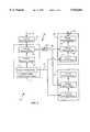
- FIG. 1is a high-level schematic diagram of a signal distribution system of the present invention.
- FIG. 2is a more detailed schematic diagram of a preferred signal distribution system of the present invention.
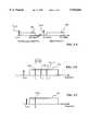
- FIG. 3-Ais a diagram showing typical high-frequency and intermediate-frequency bands according to the present invention.
- FIG. 3-Bshows the high-frequency band of FIG. 3-A.
- FIG. 3-Cshows the intermediate-frequency band of FIG. 3-A.
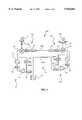
- FIG. 4is a schematic diagram of an alternative signal distribution system of the present invention.
- FIG. 1is a high-level schematic diagram of a system 20 of the present invention.
- System 20is particularly suited for wireless communications distribution in buildings or complex areas.
- System 20is bidirectional; however, for clarity of presentation only one communication direction (downlink) is illustrated in the discussion below.
- System 20comprises a central subsystem 22 in communication with a plurality of remote subsystems 24, 24' over an intermediate-frequency (IF) transmission means 26.
- IFintermediate-frequency
- Subsystem 24'is identical in structure and operation to subsystem 24.
- Central subsystem 22comprises a central receiving means 30 for receiving a central high-frequency signal 32.
- Receiving means 30preferably comprises a central radio-frequency antenna for wireless communications, typically situated on a rooftop.
- receiving means 30comprises an interface to a cable or fiberoptic high-frequency distribution network, typically situated in a building basement.
- Central subsystem 22further comprises a central tunable channel selection means 10 in communication with receiving means 30.
- channel selection means 10tunably selects at least one channel C k! for emission by remote subsystem 24.
- the index kcan take in general any value between 1 and J. The value of the index k can be tuned during the operation of system 20.
- Channel selection means 10comprises a central mixing means (mixer) 60.
- Mixer 60may be any suitable single-ended, balanced, double balanced, double-double balanced, or other mixer.
- An input of mixer 60is connected to receiving means 30 over a link capable of accurately transmitting signal 32.
- Another input of mixer 60is connected to an output of a central reference means 82.
- Central reference means 82generates a central reference signal, preferably consisting of a single sinusoid.
- An input of central reference means 82is in communication with an output of a global tuning means 12.
- An output of mixer 60is connected to a selection filter 62 and to transmission means 26.
- Mixer 60generates an intermediate signal by mixing the central reference signal and the central high-frequency signal.
- the intermediate signalcomprises two frequency bands, corresponding to the sum and difference, respectively, of the central high-frequency signal and central reference signal frequencies.
- the intermediate signalcomprises a channel C' k! corresponding to the channel C k!.
- Global tuning means 12controls the frequency of the central reference signal, such that channel C' k! is suitable for transmission through filter 62.
- Filter 62allows channel C' k! for passage through transmission means 26, and filters out other channels ⁇ C j! ⁇ , j k.
- transmission means 26is not suitable for transmitting high-frequency signals, but is suitable for transmitting intermediate-frequency signals.
- the channel C' k!then corresponds to the frequency difference between the central high-frequency signal and the central reference signal, such that C' k! is centered at a lower frequency than C k!.
- Remote subsystem 24comprises a remote mixer 40, a remote reference means 52, and a remote emission means 54.
- Remote emission means 54preferably comprises a repeater antenna for wireless communications, typically situated within a building or other complex area where coverage is desired.
- One input of mixer 40is in communication with the output of mixer 60 over transmission means 26. and filter 62, while another input of mixer 40 is connected to an output of remote reference means 52.
- Remote reference means 52generates a remote reference signal, preferably consisting of a single sinusoid.
- An input of remote reference means 52is connected to an output of global tuning means 12.
- An output of mixer 40is connected to an input of emission means 54.
- Mixer 40generates a remote high-frequency signal by mixing the intermediate signal and the remote reference signal.
- the high-frequency signalconsists essentially of the channel C k!.
- Global tuning means 12controls the frequency of the remote reference signal, preferably such that it is equal to the frequency of the central reference signal.
- FIG. 2is a more detailed schematic diagram of a preferred design for system 20.
- Central reference means 82comprises a central reference oscillator (local oscillator) 80.
- the frequency of the signal emitted by oscillator 80is proportional to the voltage at the control input of oscillator 80.
- Oscillator 80is preferably a voltage-controlled high-frequency oscillator which by itself would emit a signal of low frequency stability. Such oscillators are desirable because of their low cost, minimal requirements on their environment, and wide tuning range, but require stabilization for adequate operation.
- Oscillator 80is stabilized by a central frequency stabilization means comprising a phase comparator 84, a tunable frequency divider 86 characterized by a tunable integer N, and a low-pass filter 88.
- the central frequency stabilization means and oscillator 80form a central phase-locked-loop (PLL), which also serves as a frequency multiplication means.
- the output of oscillator 80is connected to an input of frequency divider 86.
- the output of divider 86is connected to an input of comparator 84.
- a second input of comparator 84(also an input for central reference means 82) is connected through filter 88 to an output of a spacing-determining frequency divider 90 characterized by a fixed integer M.
- the input of divider 90is connected to an output of a high-stability global reference oscillator 92.
- Oscillator 92is preferably a temperature-stabilized crystal oscillator (TCXO) with very low phase noise. Such devices are commercially available, though relatively costly.
- a high-stability signal generated using oscillator 92is delivered to an input of phase-comparator 84 (also the input of central reference means 82).
- Another input of phase comparator 84receives a signal from divider 86, generated by frequency-dividing the central reference signal by a tunable integer N.
- the output of comparator 84is connected through filter 88 to a control input of oscillator 80.
- Comparator 84produces a central adjustment signal representative of the phase difference between the two signals received at its inputs.
- the central adjustment signaldrives oscillator 80.
- the central reference signal generated by oscillator 80is thus frequency-stabilized using the high-stability signal generated by oscillator 92.
- the output of oscillator 80is connected to an input of a reference frequency divider 94 characterized by an integer P.
- the output of divider 94is connected to a low-pass filter 96 and to transmission means 26.
- Divider 94 and filter 96produce a high-stability global tuning signal by frequency-dividing and filtering the central reference signal.
- Filter 96is a bandpass or low-pass filter for eliminating undesirable high-frequency components from the signal generated by divider 94.
- Divider 94is useful when the central reference signal is of a high-frequency, and thus cannot serve as a global tuning signal to be transmitted through transmission means 26.
- the number P characterizing divider 94is chosen such that the global tuning signal is of a frequency suitable for transmission through transmission means 26, and such that the frequency bands of the global tuning signal and the intermediate signal do not overlap. In one implementation, the number P is 256.
- a summing means 98adds the signals from the outputs of mixer 60 and divider 94 for transmission through a common transmission line.
- a filter 65selects the intermediate signal for transmission to mixer 40, while a filter 67 selects the global tuning signal for transmission to remote reference means 52.
- Remote reference means 52comprises an oscillator 44, which is preferably a voltage-controlled high-frequency oscillator similar to oscillator 80. Oscillator 44 would produce by itself a low-stability signal. Oscillator 44 is stabilized by a remote frequency stabilization means.
- the frequency stabilization meanscomprises a phase comparator 46, a frequency divider 48 characterized by the integer P characterizing divider 94, and a low-pass filter 50.
- the remote frequency stabilization means and oscillator 44form a remote phase-locked-loop (PLL).
- the output of oscillator 44is connected to an input of frequency divider 48.
- the output of divider 48is connected to an input of comparator 46.
- a second input of comparator 46is connected to the output of divider 94 over transmission means 26, through filter 96 and filter 67. The output of comparator 46 is connected to a control input of oscillator 44.
- the remote reference signal generated by remote reference means 52is frequency-stabilized using the global tuning signal received through transmission means 26.
- Phase comparator 46receives at one input the global tuning signal, and at the other a signal generated by frequency divider 48 by dividing the remote reference signal by the number P.
- Phase comparator 46produces a remote adjustment signal reflecting the phase mismatch between the global tuning signal and the remote reference signal.
- the remote adjustment signaldrives oscillator 44.
- Remote reference means 52essentially multiplies by P the global tuning signal, generating a signal (the remote reference signal) that is substantially identical to the central reference signal.
- High-frequency signal 32spans a high-frequency band 100, as illustrated in FIG. 3-A.
- signal 32spans the AMPS frequency band between 824 and 894 MHz. More generally, signal 32 is within a frequency band commonly used for cellular communications, cordless telephony, personal communication services (PCS), local radio-frequency communications, satellite television, interactive multimedia video, or high-bit rate local area networks (LANs).
- PCSpersonal communication services
- LANslocal area networks
- FIG. 3-Bshows several channels C j!, C j+1!, C j+2! of signal 32, centered at frequencies f j , f j+1 , and f j+2 respectively.
- Adjacent channelsare separated by an interchannel spacing S, typically on the order of 1 MHz for CDMA signals.
- FIG. 3-Cillustrates a channel C' k! of the intermediate signal, corresponding to a channel C k! selected for emission.
- the frequency f CRSis tuned such that channel C' k! is within a predetermined frequency range defined by filter 62. Only frequencies in that predetermined range are transmitted through transmission means 26.
- the frequency band allowed by filter 62be centered at a (fixed) frequency f F .
- the frequency fCRSis preferably varied in increments of the interchannel spacing S, by varying the number N (characterizing divider 86) between integer values. Varying the number N allows the selection of different channels at different times. The number N satisfies the relation
- f CRMis the frequency of the signal received by central reference means 82
- Mis the integer characterizing divider 90
- f HSOis the frequency of the signal emitted by high-stability oscillator 92.
- Ndetermines f CRS . If the kth channel C k! of signal 32 is selected for transmission, Eq. 1! can be re-written as
- f 1is the frequency of the first (lowest-frequency) channel of signal 32. If f HSO and M satisfy the relation
- filter 62is tuned to channels of signal 32 for integer values of N.
- f HSO and f Fare preferably chosen such that eqs. 3! and 4! are satisfied for integer values of M and N.
- the (fixed) number Mcan be thought to determine the frequency step size of central reference means 82 as N is varied between integer values, while the number N determines which channel of signal 32 is transmitted through transmission means 26.
- System 20is advantageous because only one cost-intensive, high-stability oscillator (oscillator 92) is required for accurate up- and down-conversion of signals.
- the other essential elements of system 20are simple, easy to install, and generally low-cost.
- Voltage-controlled oscillatorssuch as oscillators 80 and 44 have low cost, and generate high-stability signals if stabilized using oscillator 92.
- Phase-locking plural remote subsystems to the same global tuning signalis advantageous since it eliminates the undesirable beating which occurs when the frequencies emitted by different remote subsystems are not exactly identical.
- FIG. 4shows a system 220 according to an alternative embodiment of the present invention.
- System 220comprises a central subsystem 222 in communication with a remote subsystem 224 over an intermediate-frequency transmission means 226.
- Transmission means 226comprises distinct transmission lines 226a, 226b for transmitting the intermediate signal and the global tuning signal, respectively.
- An analog-to-digital converter 261digitizes the intermediate signal after passage through filter 62, and before passage through transmission line 226a.
- An amplifier 263amplifies the intermediate signal after passage through transmission line 226a and a digital-to-analog converter 265.
- a global tuning signal generated by oscillator 92is transmitted over transmission means 2266 to an input of a remote reference means 252.
- Remote reference means 252comprises a frequency divider 251 between transmission means 226 and phase comparator 46, and a frequency divider 253 between the output of oscillator 44 and the other input of comparator 46.
- Dividers 251 and 253are characterized by integer numbers M and N, respectively, such that the remote reference signal generated by remote reference means 252 is substantially identical to the central reference signal generated by central reference means 82.
- the number N required for tuning remote reference means 252 to a desired emission frequencyis transmitted from central subsystem 222 to divider 253, for example as a bit serial data stream.
- Remote reference means 252is relatively complex, since the operation it performs is dependent on the channel selected (i.e. is not fixed).
- the global tuning signalcan be thought to include both the high-stability signal generated by oscillator 92, and the signal encoding the number N transmitted to divider 253.
Landscapes
- Engineering & Computer Science (AREA)
- Computer Networks & Wireless Communication (AREA)
- Signal Processing (AREA)
- Power Engineering (AREA)
- Radio Relay Systems (AREA)
- Mobile Radio Communication Systems (AREA)
- Transceivers (AREA)
Abstract
Description
N=f.sub.CRS /f.sub.CRM =M·f.sub.CRS /f.sub.HSO 1!
N=(M/f.sub.HSO)(f.sub.k -f.sub.F)=(M/f.sub.HSO)(f.sub.1 +(k-1)S-f.sub.F), 2!
M/f.sub.HSO =1/S, 3!
N=(f.sub.1 -f.sub.F)/S+k-1=constant+k. 4!
Claims (27)
Priority Applications (2)
| Application Number | Priority Date | Filing Date | Title |
|---|---|---|---|
| US08/864,298US5930682A (en) | 1996-04-19 | 1997-05-28 | Centralized channel selection in a distributed RF antenna system |
| PCT/US1998/006978WO1998054844A1 (en) | 1997-05-28 | 1998-04-07 | Centralized channel selection in a distributed rf antenna system |
Applications Claiming Priority (2)
| Application Number | Priority Date | Filing Date | Title |
|---|---|---|---|
| US63536896A | 1996-04-19 | 1996-04-19 | |
| US08/864,298US5930682A (en) | 1996-04-19 | 1997-05-28 | Centralized channel selection in a distributed RF antenna system |
Related Parent Applications (1)
| Application Number | Title | Priority Date | Filing Date |
|---|---|---|---|
| US63536896AContinuation-In-Part | 1996-04-19 | 1996-04-19 |
Publications (1)
| Publication Number | Publication Date |
|---|---|
| US5930682Atrue US5930682A (en) | 1999-07-27 |
Family
ID=25342954
Family Applications (1)
| Application Number | Title | Priority Date | Filing Date |
|---|---|---|---|
| US08/864,298Expired - LifetimeUS5930682A (en) | 1996-04-19 | 1997-05-28 | Centralized channel selection in a distributed RF antenna system |
Country Status (2)
| Country | Link |
|---|---|
| US (1) | US5930682A (en) |
| WO (1) | WO1998054844A1 (en) |
Cited By (93)
| Publication number | Priority date | Publication date | Assignee | Title |
|---|---|---|---|---|
| KR20020005160A (en)* | 2000-07-08 | 2002-01-17 | Didim Power Co Ltd | / An audio/video system for sports centers |
| US20020039885A1 (en)* | 1999-11-01 | 2002-04-04 | Haim Weissman | Split repeater |
| US6501942B1 (en)* | 1999-10-29 | 2002-12-31 | Qualcomm, Incorporated | In-building radio-frequency coverage |
| US20040176034A1 (en)* | 2003-02-13 | 2004-09-09 | Hunter Jeffrey K. | Systems and methods for reducing radio receiver interference from an on-board avionics transmitter |
| US20040185794A1 (en)* | 2003-01-30 | 2004-09-23 | Chang-Rae Jeong | Multi-sector in-building repeater |
| US20040209568A1 (en)* | 1999-06-11 | 2004-10-21 | Allgon Ab | Method and apparatus for stability margin determination in a repeater |
| US20040227683A1 (en)* | 2003-02-26 | 2004-11-18 | Caimi Frank M. | Integrated front end antenna |
| US20050088999A1 (en)* | 2002-01-31 | 2005-04-28 | Waylett Nicholas S. | Communication system having a community wireless local area network for voice and high speed data communication |
| US6973328B1 (en)* | 1999-06-07 | 2005-12-06 | Sharp Kabushiki Kaisha | Millimeter wave band transmitter, millimeter wave band receiver and millimeter wave band communication apparatus carrying out radio communication in millimeter wave band region |
| US20060227898A1 (en)* | 2003-07-10 | 2006-10-12 | Gibson Timothy P | Radio receiver |
| US7277727B1 (en)* | 2000-11-22 | 2007-10-02 | Sprint Communications Company L.P. | System and method for processing a signal |
| US20070248358A1 (en)* | 2006-04-19 | 2007-10-25 | Michael Sauer | Electrical-optical cable for wireless systems |
| US20070286599A1 (en)* | 2006-06-12 | 2007-12-13 | Michael Sauer | Centralized optical-fiber-based wireless picocellular systems and methods |
| US20070292136A1 (en)* | 2006-06-16 | 2007-12-20 | Michael Sauer | Transponder for a radio-over-fiber optical fiber cable |
| US20080014948A1 (en)* | 2006-07-14 | 2008-01-17 | Lgc Wireless, Inc. | System for and method of for providing dedicated capacity in a cellular network |
| US20080044186A1 (en)* | 2006-08-16 | 2008-02-21 | Jacob George | Radio-over-fiber transponder with a dual-band patch antenna system |
| US20080058018A1 (en)* | 2006-08-29 | 2008-03-06 | Lgc Wireless, Inc. | Distributed antenna communications system and methods of implementing thereof |
| US20080080863A1 (en)* | 2006-09-28 | 2008-04-03 | Michael Sauer | Radio-over-fiber (RoF) wireless picocellular system with combined picocells |
| US20080084861A1 (en)* | 2006-10-10 | 2008-04-10 | Honeywell International Inc. | Avionics communication system and method utilizing multi-channel radio technology and a shared data bus |
| US20080151846A1 (en)* | 2006-12-22 | 2008-06-26 | Stefan Scheinert | System for and method of providing remote coverage area for wireless communications |
| US20080181171A1 (en)* | 2007-01-25 | 2008-07-31 | Adc Telecommunications, Inc. | Distributed remote base station system |
| US20080181282A1 (en)* | 2007-01-25 | 2008-07-31 | Adc Telecommunications, Inc. | Modular wireless communications platform |
| US20080186143A1 (en)* | 2007-02-06 | 2008-08-07 | Jacob George | Transponder systems and methods for radio-over-fiber (ROF) wireless picocellular systems |
| US20080232328A1 (en)* | 2007-03-23 | 2008-09-25 | Stefan Scheinert | Localization of a mobile device in distributed antenna communications system |
| US20090005096A1 (en)* | 2007-06-26 | 2009-01-01 | Stefan Scheinert | Distributed antenna communications system |
| US20090017777A1 (en)* | 2007-07-13 | 2009-01-15 | Honeywell International Inc. | Reconfigurable aircraft radio communications system |
| US20090061940A1 (en)* | 2007-08-31 | 2009-03-05 | Stefan Scheinert | System for and method of configuring distributed antenna communications system |
| US20090298451A1 (en)* | 2008-05-29 | 2009-12-03 | Honeywell International Inc. | Reconfigurable aircraft communications system with integrated avionics communication router and audio management functions |
| US7633966B2 (en) | 2000-04-19 | 2009-12-15 | Mosaid Technologies Incorporated | Network combining wired and non-wired segments |
| US7787823B2 (en) | 2006-09-15 | 2010-08-31 | Corning Cable Systems Llc | Radio-over-fiber (RoF) optical fiber cable system with transponder diversity and RoF wireless picocellular system using same |
| US7805073B2 (en) | 2006-04-28 | 2010-09-28 | Adc Telecommunications, Inc. | Systems and methods of optical path protection for distributed antenna systems |
| US7813451B2 (en) | 2006-01-11 | 2010-10-12 | Mobileaccess Networks Ltd. | Apparatus and method for frequency shifting of a wireless signal and systems using frequency shifting |
| US20110200325A1 (en)* | 2010-02-15 | 2011-08-18 | Andrey Kobyakov | Dynamic Cell Bonding (DCB) for Radio-over-Fiber (RoF)-Based Networks and Communication Systems and Related Methods |
| US20110237182A1 (en)* | 2010-03-25 | 2011-09-29 | Adc Telecommunications, Inc. | Automatic gain control configuration for a wideband distributed antenna system |
| US8175649B2 (en) | 2008-06-20 | 2012-05-08 | Corning Mobileaccess Ltd | Method and system for real time control of an active antenna over a distributed antenna system |
| US8175459B2 (en) | 2007-10-12 | 2012-05-08 | Corning Cable Systems Llc | Hybrid wireless/wired RoF transponder and hybrid RoF communication system using same |
| US8325693B2 (en) | 2004-05-06 | 2012-12-04 | Corning Mobileaccess Ltd | System and method for carrying a wireless based signal over wiring |
| US8548330B2 (en) | 2009-07-31 | 2013-10-01 | Corning Cable Systems Llc | Sectorization in distributed antenna systems, and related components and methods |
| US8594133B2 (en) | 2007-10-22 | 2013-11-26 | Corning Mobileaccess Ltd. | Communication system using low bandwidth wires |
| US8644844B2 (en) | 2007-12-20 | 2014-02-04 | Corning Mobileaccess Ltd. | Extending outdoor location based services and applications into enclosed areas |
| US8711993B2 (en) | 2010-12-10 | 2014-04-29 | Honeywell International Inc. | Wideband multi-channel receiver with fixed-frequency notch filter for interference rejection |
| US8867919B2 (en) | 2007-07-24 | 2014-10-21 | Corning Cable Systems Llc | Multi-port accumulator for radio-over-fiber (RoF) wireless picocellular systems |
| US20140313992A1 (en)* | 2013-04-18 | 2014-10-23 | Buffalo Inc. | System and information processing apparatus |
| US8873585B2 (en) | 2006-12-19 | 2014-10-28 | Corning Optical Communications Wireless Ltd | Distributed antenna system for MIMO technologies |
| US8897215B2 (en) | 2009-02-08 | 2014-11-25 | Corning Optical Communications Wireless Ltd | Communication system using cables carrying ethernet signals |
| US9037143B2 (en) | 2010-08-16 | 2015-05-19 | Corning Optical Communications LLC | Remote antenna clusters and related systems, components, and methods supporting digital data signal propagation between remote antenna units |
| US9042732B2 (en) | 2010-05-02 | 2015-05-26 | Corning Optical Communications LLC | Providing digital data services in optical fiber-based distributed radio frequency (RF) communication systems, and related components and methods |
| US9112611B2 (en) | 2009-02-03 | 2015-08-18 | Corning Optical Communications LLC | Optical fiber-based distributed antenna systems, components, and related methods for calibration thereof |
| US9178635B2 (en) | 2014-01-03 | 2015-11-03 | Corning Optical Communications Wireless Ltd | Separation of communication signal sub-bands in distributed antenna systems (DASs) to reduce interference |
| US9184843B2 (en) | 2011-04-29 | 2015-11-10 | Corning Optical Communications LLC | Determining propagation delay of communications in distributed antenna systems, and related components, systems, and methods |
| US9184960B1 (en) | 2014-09-25 | 2015-11-10 | Corning Optical Communications Wireless Ltd | Frequency shifting a communications signal(s) in a multi-frequency distributed antenna system (DAS) to avoid or reduce frequency interference |
| US9219879B2 (en) | 2009-11-13 | 2015-12-22 | Corning Optical Communications LLC | Radio-over-fiber (ROF) system for protocol-independent wired and/or wireless communication |
| US9240835B2 (en) | 2011-04-29 | 2016-01-19 | Corning Optical Communications LLC | Systems, methods, and devices for increasing radio frequency (RF) power in distributed antenna systems |
| US9247543B2 (en) | 2013-07-23 | 2016-01-26 | Corning Optical Communications Wireless Ltd | Monitoring non-supported wireless spectrum within coverage areas of distributed antenna systems (DASs) |
| US9258052B2 (en) | 2012-03-30 | 2016-02-09 | Corning Optical Communications LLC | Reducing location-dependent interference in distributed antenna systems operating in multiple-input, multiple-output (MIMO) configuration, and related components, systems, and methods |
| US9325429B2 (en) | 2011-02-21 | 2016-04-26 | Corning Optical Communications LLC | Providing digital data services as electrical signals and radio-frequency (RF) communications over optical fiber in distributed communications systems, and related components and methods |
| US9338823B2 (en) | 2012-03-23 | 2016-05-10 | Corning Optical Communications Wireless Ltd | Radio-frequency integrated circuit (RFIC) chip(s) for providing distributed antenna system functionalities, and related components, systems, and methods |
| US9357551B2 (en) | 2014-05-30 | 2016-05-31 | Corning Optical Communications Wireless Ltd | Systems and methods for simultaneous sampling of serial digital data streams from multiple analog-to-digital converters (ADCS), including in distributed antenna systems |
| US9385810B2 (en) | 2013-09-30 | 2016-07-05 | Corning Optical Communications Wireless Ltd | Connection mapping in distributed communication systems |
| US9420542B2 (en) | 2014-09-25 | 2016-08-16 | Corning Optical Communications Wireless Ltd | System-wide uplink band gain control in a distributed antenna system (DAS), based on per band gain control of remote uplink paths in remote units |
| US9455784B2 (en) | 2012-10-31 | 2016-09-27 | Corning Optical Communications Wireless Ltd | Deployable wireless infrastructures and methods of deploying wireless infrastructures |
| US9525472B2 (en) | 2014-07-30 | 2016-12-20 | Corning Incorporated | Reducing location-dependent destructive interference in distributed antenna systems (DASS) operating in multiple-input, multiple-output (MIMO) configuration, and related components, systems, and methods |
| US9525488B2 (en) | 2010-05-02 | 2016-12-20 | Corning Optical Communications LLC | Digital data services and/or power distribution in optical fiber-based distributed communications systems providing digital data and radio frequency (RF) communications services, and related components and methods |
| US9531452B2 (en) | 2012-11-29 | 2016-12-27 | Corning Optical Communications LLC | Hybrid intra-cell / inter-cell remote unit antenna bonding in multiple-input, multiple-output (MIMO) distributed antenna systems (DASs) |
| US9565596B2 (en) | 2011-08-29 | 2017-02-07 | Commscope Technologies Llc | Configuring a distributed antenna system |
| US9602210B2 (en) | 2014-09-24 | 2017-03-21 | Corning Optical Communications Wireless Ltd | Flexible head-end chassis supporting automatic identification and interconnection of radio interface modules and optical interface modules in an optical fiber-based distributed antenna system (DAS) |
| US9621293B2 (en) | 2012-08-07 | 2017-04-11 | Corning Optical Communications Wireless Ltd | Distribution of time-division multiplexed (TDM) management services in a distributed antenna system, and related components, systems, and methods |
| US9647758B2 (en) | 2012-11-30 | 2017-05-09 | Corning Optical Communications Wireless Ltd | Cabling connectivity monitoring and verification |
| US9661781B2 (en) | 2013-07-31 | 2017-05-23 | Corning Optical Communications Wireless Ltd | Remote units for distributed communication systems and related installation methods and apparatuses |
| US9673904B2 (en) | 2009-02-03 | 2017-06-06 | Corning Optical Communications LLC | Optical fiber-based distributed antenna systems, components, and related methods for calibration thereof |
| US9681313B2 (en) | 2015-04-15 | 2017-06-13 | Corning Optical Communications Wireless Ltd | Optimizing remote antenna unit performance using an alternative data channel |
| US9715157B2 (en) | 2013-06-12 | 2017-07-25 | Corning Optical Communications Wireless Ltd | Voltage controlled optical directional coupler |
| US9729267B2 (en) | 2014-12-11 | 2017-08-08 | Corning Optical Communications Wireless Ltd | Multiplexing two separate optical links with the same wavelength using asymmetric combining and splitting |
| US9730228B2 (en) | 2014-08-29 | 2017-08-08 | Corning Optical Communications Wireless Ltd | Individualized gain control of remote uplink band paths in a remote unit in a distributed antenna system (DAS), based on combined uplink power level in the remote unit |
| US9775123B2 (en) | 2014-03-28 | 2017-09-26 | Corning Optical Communications Wireless Ltd. | Individualized gain control of uplink paths in remote units in a distributed antenna system (DAS) based on individual remote unit contribution to combined uplink power |
| US9807700B2 (en) | 2015-02-19 | 2017-10-31 | Corning Optical Communications Wireless Ltd | Offsetting unwanted downlink interference signals in an uplink path in a distributed antenna system (DAS) |
| US9867052B2 (en) | 2000-03-27 | 2018-01-09 | Commscope Technologies Llc | Multiprotocol antenna system for multiple service providers |
| US9948349B2 (en) | 2015-07-17 | 2018-04-17 | Corning Optical Communications Wireless Ltd | IOT automation and data collection system |
| US9974074B2 (en) | 2013-06-12 | 2018-05-15 | Corning Optical Communications Wireless Ltd | Time-division duplexing (TDD) in distributed communications systems, including distributed antenna systems (DASs) |
| US10096909B2 (en) | 2014-11-03 | 2018-10-09 | Corning Optical Communications Wireless Ltd. | Multi-band monopole planar antennas configured to facilitate improved radio frequency (RF) isolation in multiple-input multiple-output (MIMO) antenna arrangement |
| US10110308B2 (en) | 2014-12-18 | 2018-10-23 | Corning Optical Communications Wireless Ltd | Digital interface modules (DIMs) for flexibly distributing digital and/or analog communications signals in wide-area analog distributed antenna systems (DASs) |
| US10128951B2 (en) | 2009-02-03 | 2018-11-13 | Corning Optical Communications LLC | Optical fiber-based distributed antenna systems, components, and related methods for monitoring and configuring thereof |
| US10136200B2 (en) | 2012-04-25 | 2018-11-20 | Corning Optical Communications LLC | Distributed antenna system architectures |
| US10135533B2 (en) | 2014-11-13 | 2018-11-20 | Corning Optical Communications Wireless Ltd | Analog distributed antenna systems (DASS) supporting distribution of digital communications signals interfaced from a digital signal source and analog radio frequency (RF) communications signals |
| US10187151B2 (en) | 2014-12-18 | 2019-01-22 | Corning Optical Communications Wireless Ltd | Digital-analog interface modules (DAIMs) for flexibly distributing digital and/or analog communications signals in wide-area analog distributed antenna systems (DASs) |
| US10236924B2 (en) | 2016-03-31 | 2019-03-19 | Corning Optical Communications Wireless Ltd | Reducing out-of-channel noise in a wireless distribution system (WDS) |
| US10499269B2 (en) | 2015-11-12 | 2019-12-03 | Commscope Technologies Llc | Systems and methods for assigning controlled nodes to channel interfaces of a controller |
| US10498434B2 (en) | 2000-07-19 | 2019-12-03 | CommScope Technolgies LLC | Point-to-multipoint digital radio frequency transport |
| US10560214B2 (en) | 2015-09-28 | 2020-02-11 | Corning Optical Communications LLC | Downlink and uplink communication path switching in a time-division duplex (TDD) distributed antenna system (DAS) |
| US10659163B2 (en) | 2014-09-25 | 2020-05-19 | Corning Optical Communications LLC | Supporting analog remote antenna units (RAUs) in digital distributed antenna systems (DASs) using analog RAU digital adaptors |
| US10785827B2 (en) | 2009-11-12 | 2020-09-22 | Andrew Wireless Systems Gmbh | Master unit, remote unit and multiband transmission system |
| US11178609B2 (en) | 2010-10-13 | 2021-11-16 | Corning Optical Communications LLC | Power management for remote antenna units in distributed antenna systems |
| USRE49377E1 (en) | 2002-12-03 | 2023-01-17 | Commscope Technologies Llc | Distributed digital antenna system |
Families Citing this family (5)
| Publication number | Priority date | Publication date | Assignee | Title |
|---|---|---|---|---|
| DE10065159A1 (en)* | 2000-12-23 | 2002-06-27 | Harris Comm Austria Gmbh Wien | Master transmitter connection |
| ES2551028T3 (en)* | 2004-01-12 | 2015-11-13 | Nextivity, Inc. | Short range cell amplifier |
| US8086174B2 (en) | 2009-04-10 | 2011-12-27 | Nextivity, Inc. | Short-range cellular booster |
| EA036403B1 (en) | 2013-09-24 | 2020-11-06 | Басф Се | Protein having cellulose:xyloglucan endotransglucosylase (cxe) activity and use thereof |
| DE102019104458B4 (en) | 2019-02-21 | 2025-08-28 | Telefonaktiebolaget Lm Ericsson (Publ) | Repeater system |
Citations (5)
| Publication number | Priority date | Publication date | Assignee | Title |
|---|---|---|---|---|
| US3922674A (en)* | 1974-01-24 | 1975-11-25 | Raytheon Co | Transponder for use in a radio frequency communication system |
| US4476574A (en)* | 1980-09-17 | 1984-10-09 | The United States Of America As Represented By The United States Department Of Energy | Radio frequency communication system utilizing radiating transmission lines |
| US4776039A (en)* | 1985-01-25 | 1988-10-04 | Nec Corporation | Receiver for mobile communication systems |
| WO1994013067A1 (en)* | 1992-11-23 | 1994-06-09 | Telefonaktiebolaget Lm Ericsson | Radio coverage in closed environments |
| US5428836A (en)* | 1992-01-21 | 1995-06-27 | Motorola Inc. | Radio receiver for forming a baseband signal of time-varying frequencies |
- 1997
- 1997-05-28USUS08/864,298patent/US5930682A/ennot_activeExpired - Lifetime
- 1998
- 1998-04-07WOPCT/US1998/006978patent/WO1998054844A1/enactiveApplication Filing
Patent Citations (7)
| Publication number | Priority date | Publication date | Assignee | Title |
|---|---|---|---|---|
| US3922674A (en)* | 1974-01-24 | 1975-11-25 | Raytheon Co | Transponder for use in a radio frequency communication system |
| US4476574A (en)* | 1980-09-17 | 1984-10-09 | The United States Of America As Represented By The United States Department Of Energy | Radio frequency communication system utilizing radiating transmission lines |
| US4776039A (en)* | 1985-01-25 | 1988-10-04 | Nec Corporation | Receiver for mobile communication systems |
| US5428836A (en)* | 1992-01-21 | 1995-06-27 | Motorola Inc. | Radio receiver for forming a baseband signal of time-varying frequencies |
| WO1994013067A1 (en)* | 1992-11-23 | 1994-06-09 | Telefonaktiebolaget Lm Ericsson | Radio coverage in closed environments |
| US5404570A (en)* | 1992-11-23 | 1995-04-04 | Telefonaktiebolaget L M Ericsson | Radio coverage in closed environments |
| US5603080A (en)* | 1992-11-23 | 1997-02-11 | Telefonaktiebolaget Lm Ericsson | Radio coverage in closed environments |
Cited By (196)
| Publication number | Priority date | Publication date | Assignee | Title |
|---|---|---|---|---|
| US6973328B1 (en)* | 1999-06-07 | 2005-12-06 | Sharp Kabushiki Kaisha | Millimeter wave band transmitter, millimeter wave band receiver and millimeter wave band communication apparatus carrying out radio communication in millimeter wave band region |
| US7398053B2 (en)* | 1999-06-11 | 2008-07-08 | Allgon Ab | Method and apparatus for stability margin determination in a repeater |
| US20040209568A1 (en)* | 1999-06-11 | 2004-10-21 | Allgon Ab | Method and apparatus for stability margin determination in a repeater |
| US6501942B1 (en)* | 1999-10-29 | 2002-12-31 | Qualcomm, Incorporated | In-building radio-frequency coverage |
| JP2003513570A (en)* | 1999-10-29 | 2003-04-08 | クゥアルコム・インコーポレイテッド | Radio frequency coverage in buildings |
| EP1224821B1 (en)* | 1999-10-29 | 2008-08-27 | QUALCOMM Incorporated | In-building radio-frequency coverage |
| US20020039885A1 (en)* | 1999-11-01 | 2002-04-04 | Haim Weissman | Split repeater |
| US9867052B2 (en) | 2000-03-27 | 2018-01-09 | Commscope Technologies Llc | Multiprotocol antenna system for multiple service providers |
| US10321328B2 (en) | 2000-03-27 | 2019-06-11 | Commscope Technologies Llc | Multiprotocol antenna system for multiple service providers |
| US7633966B2 (en) | 2000-04-19 | 2009-12-15 | Mosaid Technologies Incorporated | Network combining wired and non-wired segments |
| US8867506B2 (en) | 2000-04-19 | 2014-10-21 | Conversant Intellectual Property Management Incorporated | Network combining wired and non-wired segments |
| US7876767B2 (en) | 2000-04-19 | 2011-01-25 | Mosaid Technologies Incorporated | Network combining wired and non-wired segments |
| US8873575B2 (en) | 2000-04-19 | 2014-10-28 | Conversant Intellectual Property Management Incorporated | Network combining wired and non-wired segments |
| US7715441B2 (en) | 2000-04-19 | 2010-05-11 | Mosaid Technologies Incorporated | Network combining wired and non-wired segments |
| US8848725B2 (en) | 2000-04-19 | 2014-09-30 | Conversant Intellectual Property Management Incorporated | Network combining wired and non-wired segments |
| US8982903B2 (en) | 2000-04-19 | 2015-03-17 | Conversant Intellectual Property Management Inc. | Network combining wired and non-wired segments |
| US7933297B2 (en) | 2000-04-19 | 2011-04-26 | Mosaid Technologies Incorporated | Network combining wired and non-wired segments |
| US8289991B2 (en) | 2000-04-19 | 2012-10-16 | Mosaid Technologies Incorporated | Network combining wired and non-wired segments |
| US8982904B2 (en) | 2000-04-19 | 2015-03-17 | Conversant Intellectual Property Management Inc. | Network combining wired and non-wired segments |
| US7636373B2 (en) | 2000-04-19 | 2009-12-22 | Mosaid Technologies Incorporated | Network combining wired and non-wired segments |
| US8873586B2 (en) | 2000-04-19 | 2014-10-28 | Conversant Intellectual Property Management Incorporated | Network combining wired and non-wired segments |
| KR20020005160A (en)* | 2000-07-08 | 2002-01-17 | Didim Power Co Ltd | / An audio/video system for sports centers |
| US10498434B2 (en) | 2000-07-19 | 2019-12-03 | CommScope Technolgies LLC | Point-to-multipoint digital radio frequency transport |
| US10505635B2 (en) | 2000-07-19 | 2019-12-10 | Commscope Technologies Llc | Point-to-multipoint digital radio frequency transport |
| US7277727B1 (en)* | 2000-11-22 | 2007-10-02 | Sprint Communications Company L.P. | System and method for processing a signal |
| US20050088999A1 (en)* | 2002-01-31 | 2005-04-28 | Waylett Nicholas S. | Communication system having a community wireless local area network for voice and high speed data communication |
| US10659970B2 (en) | 2002-01-31 | 2020-05-19 | Commscope Technologies Llc | Communication system having a community wireless local area network for voice and high speed data communication |
| US8184603B2 (en) | 2002-01-31 | 2012-05-22 | Lgc Wireless, Llc | Communication system having a community wireless local area network for voice and high speed data communication |
| USRE49377E1 (en) | 2002-12-03 | 2023-01-17 | Commscope Technologies Llc | Distributed digital antenna system |
| USRE50112E1 (en) | 2002-12-03 | 2024-09-03 | Outdoor Wireless Networks LLC | Distributed digital antenna system |
| US20040185794A1 (en)* | 2003-01-30 | 2004-09-23 | Chang-Rae Jeong | Multi-sector in-building repeater |
| US7272362B2 (en)* | 2003-01-30 | 2007-09-18 | Samsung Electronics Co., Ltd. | Multi-sector in-building repeater |
| US20040176034A1 (en)* | 2003-02-13 | 2004-09-09 | Hunter Jeffrey K. | Systems and methods for reducing radio receiver interference from an on-board avionics transmitter |
| US7142818B2 (en)* | 2003-02-13 | 2006-11-28 | Honeywell International, Inc. | Systems and methods for reducing radio receiver interference from an on-board avionics transmitter |
| US20060270368A1 (en)* | 2003-02-26 | 2006-11-30 | Caimi Frank M | Integrated Front End Antenna |
| US7084823B2 (en) | 2003-02-26 | 2006-08-01 | Skycross, Inc. | Integrated front end antenna |
| US20040227683A1 (en)* | 2003-02-26 | 2004-11-18 | Caimi Frank M. | Integrated front end antenna |
| US20060227898A1 (en)* | 2003-07-10 | 2006-10-12 | Gibson Timothy P | Radio receiver |
| US8325693B2 (en) | 2004-05-06 | 2012-12-04 | Corning Mobileaccess Ltd | System and method for carrying a wireless based signal over wiring |
| US8325759B2 (en) | 2004-05-06 | 2012-12-04 | Corning Mobileaccess Ltd | System and method for carrying a wireless based signal over wiring |
| US8184681B2 (en) | 2006-01-11 | 2012-05-22 | Corning Mobileaccess Ltd | Apparatus and method for frequency shifting of a wireless signal and systems using frequency shifting |
| US20110206088A1 (en)* | 2006-01-11 | 2011-08-25 | Mobileaccess Networks Ltd. | Apparatus and method for frequency shifting of a wireless signal and systems using frequency shifting |
| US7813451B2 (en) | 2006-01-11 | 2010-10-12 | Mobileaccess Networks Ltd. | Apparatus and method for frequency shifting of a wireless signal and systems using frequency shifting |
| US20070248358A1 (en)* | 2006-04-19 | 2007-10-25 | Michael Sauer | Electrical-optical cable for wireless systems |
| US7805073B2 (en) | 2006-04-28 | 2010-09-28 | Adc Telecommunications, Inc. | Systems and methods of optical path protection for distributed antenna systems |
| US10411805B2 (en) | 2006-04-28 | 2019-09-10 | Commscope Technologies Llc | Systems and methods of optical path protection for distributed antenna systems |
| US8135273B2 (en) | 2006-04-28 | 2012-03-13 | Adc Telecommunications, Inc. | Systems and methods of optical path protection for distributed antenna systems |
| US20110002687A1 (en)* | 2006-04-28 | 2011-01-06 | Adc Telecommunications, Inc. | Systems and methods of optical path protection for distributed antenna systems |
| US8805182B2 (en) | 2006-04-28 | 2014-08-12 | Adc Telecommunications Inc. | Systems and methods of optical path protection for distributed antenna systems |
| US9843391B2 (en) | 2006-04-28 | 2017-12-12 | Commscope Technologies Llc | Systems and methods of optical path protection for distributed antenna systems |
| US20070286599A1 (en)* | 2006-06-12 | 2007-12-13 | Michael Sauer | Centralized optical-fiber-based wireless picocellular systems and methods |
| US20070292136A1 (en)* | 2006-06-16 | 2007-12-20 | Michael Sauer | Transponder for a radio-over-fiber optical fiber cable |
| US7590354B2 (en) | 2006-06-16 | 2009-09-15 | Corning Cable Systems Llc | Redundant transponder array for a radio-over-fiber optical fiber cable |
| US7844273B2 (en) | 2006-07-14 | 2010-11-30 | Lgc Wireless, Inc. | System for and method of for providing dedicated capacity in a cellular network |
| US20080014948A1 (en)* | 2006-07-14 | 2008-01-17 | Lgc Wireless, Inc. | System for and method of for providing dedicated capacity in a cellular network |
| US20080044186A1 (en)* | 2006-08-16 | 2008-02-21 | Jacob George | Radio-over-fiber transponder with a dual-band patch antenna system |
| US7627250B2 (en) | 2006-08-16 | 2009-12-01 | Corning Cable Systems Llc | Radio-over-fiber transponder with a dual-band patch antenna system |
| US7848770B2 (en) | 2006-08-29 | 2010-12-07 | Lgc Wireless, Inc. | Distributed antenna communications system and methods of implementing thereof |
| US20080058018A1 (en)* | 2006-08-29 | 2008-03-06 | Lgc Wireless, Inc. | Distributed antenna communications system and methods of implementing thereof |
| US7787823B2 (en) | 2006-09-15 | 2010-08-31 | Corning Cable Systems Llc | Radio-over-fiber (RoF) optical fiber cable system with transponder diversity and RoF wireless picocellular system using same |
| US7848654B2 (en) | 2006-09-28 | 2010-12-07 | Corning Cable Systems Llc | Radio-over-fiber (RoF) wireless picocellular system with combined picocells |
| US20080080863A1 (en)* | 2006-09-28 | 2008-04-03 | Michael Sauer | Radio-over-fiber (RoF) wireless picocellular system with combined picocells |
| US20080084861A1 (en)* | 2006-10-10 | 2008-04-10 | Honeywell International Inc. | Avionics communication system and method utilizing multi-channel radio technology and a shared data bus |
| US9130613B2 (en) | 2006-12-19 | 2015-09-08 | Corning Optical Communications Wireless Ltd | Distributed antenna system for MIMO technologies |
| US8873585B2 (en) | 2006-12-19 | 2014-10-28 | Corning Optical Communications Wireless Ltd | Distributed antenna system for MIMO technologies |
| US7817958B2 (en) | 2006-12-22 | 2010-10-19 | Lgc Wireless Inc. | System for and method of providing remote coverage area for wireless communications |
| US20080151846A1 (en)* | 2006-12-22 | 2008-06-26 | Stefan Scheinert | System for and method of providing remote coverage area for wireless communications |
| US9585193B2 (en) | 2007-01-25 | 2017-02-28 | Commscope Technologies Llc | Modular wireless communications platform |
| US8737454B2 (en) | 2007-01-25 | 2014-05-27 | Adc Telecommunications, Inc. | Modular wireless communications platform |
| US9941921B2 (en) | 2007-01-25 | 2018-04-10 | Commscope Technologies Llc | Modular wireless communications platform |
| US20080181282A1 (en)* | 2007-01-25 | 2008-07-31 | Adc Telecommunications, Inc. | Modular wireless communications platform |
| US8583100B2 (en) | 2007-01-25 | 2013-11-12 | Adc Telecommunications, Inc. | Distributed remote base station system |
| US10554242B2 (en) | 2007-01-25 | 2020-02-04 | Commscope Technologies Llc | Modular wireless communications platform |
| US20080181171A1 (en)* | 2007-01-25 | 2008-07-31 | Adc Telecommunications, Inc. | Distributed remote base station system |
| US20080186143A1 (en)* | 2007-02-06 | 2008-08-07 | Jacob George | Transponder systems and methods for radio-over-fiber (ROF) wireless picocellular systems |
| US8111998B2 (en) | 2007-02-06 | 2012-02-07 | Corning Cable Systems Llc | Transponder systems and methods for radio-over-fiber (RoF) wireless picocellular systems |
| US20080232328A1 (en)* | 2007-03-23 | 2008-09-25 | Stefan Scheinert | Localization of a mobile device in distributed antenna communications system |
| US8005050B2 (en) | 2007-03-23 | 2011-08-23 | Lgc Wireless, Inc. | Localization of a mobile device in distributed antenna communications system |
| USRE45505E1 (en) | 2007-03-23 | 2015-05-05 | Adc Telecommunications, Inc. | Localization of a mobile device in distributed antenna communications system |
| US8229497B2 (en) | 2007-06-26 | 2012-07-24 | Lgc Wireless, Llc | Distributed antenna communications system |
| US8010116B2 (en) | 2007-06-26 | 2011-08-30 | Lgc Wireless, Inc. | Distributed antenna communications system |
| US20090005096A1 (en)* | 2007-06-26 | 2009-01-01 | Stefan Scheinert | Distributed antenna communications system |
| US8532698B2 (en) | 2007-06-26 | 2013-09-10 | Adc Telecommunications, Inc. | Distributed antenna communications system |
| US8081933B2 (en) | 2007-07-13 | 2011-12-20 | Honeywell International Inc. | Reconfigurable aircraft radio communications system |
| US20090017777A1 (en)* | 2007-07-13 | 2009-01-15 | Honeywell International Inc. | Reconfigurable aircraft radio communications system |
| US8867919B2 (en) | 2007-07-24 | 2014-10-21 | Corning Cable Systems Llc | Multi-port accumulator for radio-over-fiber (RoF) wireless picocellular systems |
| US9112547B2 (en) | 2007-08-31 | 2015-08-18 | Adc Telecommunications, Inc. | System for and method of configuring distributed antenna communications system |
| US20090061940A1 (en)* | 2007-08-31 | 2009-03-05 | Stefan Scheinert | System for and method of configuring distributed antenna communications system |
| US8718478B2 (en) | 2007-10-12 | 2014-05-06 | Corning Cable Systems Llc | Hybrid wireless/wired RoF transponder and hybrid RoF communication system using same |
| US8175459B2 (en) | 2007-10-12 | 2012-05-08 | Corning Cable Systems Llc | Hybrid wireless/wired RoF transponder and hybrid RoF communication system using same |
| US9813229B2 (en) | 2007-10-22 | 2017-11-07 | Corning Optical Communications Wireless Ltd | Communication system using low bandwidth wires |
| US8594133B2 (en) | 2007-10-22 | 2013-11-26 | Corning Mobileaccess Ltd. | Communication system using low bandwidth wires |
| US9549301B2 (en) | 2007-12-17 | 2017-01-17 | Corning Optical Communications Wireless Ltd | Method and system for real time control of an active antenna over a distributed antenna system |
| US8644844B2 (en) | 2007-12-20 | 2014-02-04 | Corning Mobileaccess Ltd. | Extending outdoor location based services and applications into enclosed areas |
| US20090298451A1 (en)* | 2008-05-29 | 2009-12-03 | Honeywell International Inc. | Reconfigurable aircraft communications system with integrated avionics communication router and audio management functions |
| US8019338B2 (en) | 2008-05-29 | 2011-09-13 | Honeywell International Inc. | Reconfigurable aircraft communications system with integrated avionics communication router and audio management functions |
| US8175649B2 (en) | 2008-06-20 | 2012-05-08 | Corning Mobileaccess Ltd | Method and system for real time control of an active antenna over a distributed antenna system |
| US9112611B2 (en) | 2009-02-03 | 2015-08-18 | Corning Optical Communications LLC | Optical fiber-based distributed antenna systems, components, and related methods for calibration thereof |
| US10128951B2 (en) | 2009-02-03 | 2018-11-13 | Corning Optical Communications LLC | Optical fiber-based distributed antenna systems, components, and related methods for monitoring and configuring thereof |
| US9673904B2 (en) | 2009-02-03 | 2017-06-06 | Corning Optical Communications LLC | Optical fiber-based distributed antenna systems, components, and related methods for calibration thereof |
| US10153841B2 (en) | 2009-02-03 | 2018-12-11 | Corning Optical Communications LLC | Optical fiber-based distributed antenna systems, components, and related methods for calibration thereof |
| US9900097B2 (en) | 2009-02-03 | 2018-02-20 | Corning Optical Communications LLC | Optical fiber-based distributed antenna systems, components, and related methods for calibration thereof |
| US8897215B2 (en) | 2009-02-08 | 2014-11-25 | Corning Optical Communications Wireless Ltd | Communication system using cables carrying ethernet signals |
| US8548330B2 (en) | 2009-07-31 | 2013-10-01 | Corning Cable Systems Llc | Sectorization in distributed antenna systems, and related components and methods |
| US10785827B2 (en) | 2009-11-12 | 2020-09-22 | Andrew Wireless Systems Gmbh | Master unit, remote unit and multiband transmission system |
| US9485022B2 (en) | 2009-11-13 | 2016-11-01 | Corning Optical Communications LLC | Radio-over-fiber (ROF) system for protocol-independent wired and/or wireless communication |
| US9219879B2 (en) | 2009-11-13 | 2015-12-22 | Corning Optical Communications LLC | Radio-over-fiber (ROF) system for protocol-independent wired and/or wireless communication |
| US9729238B2 (en) | 2009-11-13 | 2017-08-08 | Corning Optical Communications LLC | Radio-over-fiber (ROF) system for protocol-independent wired and/or wireless communication |
| US9319138B2 (en) | 2010-02-15 | 2016-04-19 | Corning Optical Communications LLC | Dynamic cell bonding (DCB) for radio-over-fiber (RoF)-based networks and communication systems and related methods |
| US20110200325A1 (en)* | 2010-02-15 | 2011-08-18 | Andrey Kobyakov | Dynamic Cell Bonding (DCB) for Radio-over-Fiber (RoF)-Based Networks and Communication Systems and Related Methods |
| US8275265B2 (en) | 2010-02-15 | 2012-09-25 | Corning Cable Systems Llc | Dynamic cell bonding (DCB) for radio-over-fiber (RoF)-based networks and communication systems and related methods |
| US8831428B2 (en) | 2010-02-15 | 2014-09-09 | Corning Optical Communications LLC | Dynamic cell bonding (DCB) for radio-over-fiber (RoF)-based networks and communication systems and related methods |
| US20110237182A1 (en)* | 2010-03-25 | 2011-09-29 | Adc Telecommunications, Inc. | Automatic gain control configuration for a wideband distributed antenna system |
| US8428510B2 (en) | 2010-03-25 | 2013-04-23 | Adc Telecommunications, Inc. | Automatic gain control configuration for a wideband distributed antenna system |
| US9853732B2 (en) | 2010-05-02 | 2017-12-26 | Corning Optical Communications LLC | Digital data services and/or power distribution in optical fiber-based distributed communications systems providing digital data and radio frequency (RF) communications services, and related components and methods |
| US9525488B2 (en) | 2010-05-02 | 2016-12-20 | Corning Optical Communications LLC | Digital data services and/or power distribution in optical fiber-based distributed communications systems providing digital data and radio frequency (RF) communications services, and related components and methods |
| US9042732B2 (en) | 2010-05-02 | 2015-05-26 | Corning Optical Communications LLC | Providing digital data services in optical fiber-based distributed radio frequency (RF) communication systems, and related components and methods |
| US9270374B2 (en) | 2010-05-02 | 2016-02-23 | Corning Optical Communications LLC | Providing digital data services in optical fiber-based distributed radio frequency (RF) communications systems, and related components and methods |
| US9037143B2 (en) | 2010-08-16 | 2015-05-19 | Corning Optical Communications LLC | Remote antenna clusters and related systems, components, and methods supporting digital data signal propagation between remote antenna units |
| US10014944B2 (en) | 2010-08-16 | 2018-07-03 | Corning Optical Communications LLC | Remote antenna clusters and related systems, components, and methods supporting digital data signal propagation between remote antenna units |
| US11178609B2 (en) | 2010-10-13 | 2021-11-16 | Corning Optical Communications LLC | Power management for remote antenna units in distributed antenna systems |
| US11224014B2 (en) | 2010-10-13 | 2022-01-11 | Corning Optical Communications LLC | Power management for remote antenna units in distributed antenna systems |
| US11671914B2 (en) | 2010-10-13 | 2023-06-06 | Corning Optical Communications LLC | Power management for remote antenna units in distributed antenna systems |
| US11212745B2 (en) | 2010-10-13 | 2021-12-28 | Corning Optical Communications LLC | Power management for remote antenna units in distributed antenna systems |
| US8913892B2 (en) | 2010-10-28 | 2014-12-16 | Coring Optical Communications LLC | Sectorization in distributed antenna systems, and related components and methods |
| US9042502B2 (en) | 2010-12-10 | 2015-05-26 | Honeywell International Inc. | Wideband multi-channel receiver with fixed-frequency notch filter for interference rejection |
| US8711993B2 (en) | 2010-12-10 | 2014-04-29 | Honeywell International Inc. | Wideband multi-channel receiver with fixed-frequency notch filter for interference rejection |
| US9325429B2 (en) | 2011-02-21 | 2016-04-26 | Corning Optical Communications LLC | Providing digital data services as electrical signals and radio-frequency (RF) communications over optical fiber in distributed communications systems, and related components and methods |
| US10205538B2 (en) | 2011-02-21 | 2019-02-12 | Corning Optical Communications LLC | Providing digital data services as electrical signals and radio-frequency (RF) communications over optical fiber in distributed communications systems, and related components and methods |
| US9813164B2 (en) | 2011-02-21 | 2017-11-07 | Corning Optical Communications LLC | Providing digital data services as electrical signals and radio-frequency (RF) communications over optical fiber in distributed communications systems, and related components and methods |
| US9807722B2 (en) | 2011-04-29 | 2017-10-31 | Corning Optical Communications LLC | Determining propagation delay of communications in distributed antenna systems, and related components, systems, and methods |
| US9806797B2 (en) | 2011-04-29 | 2017-10-31 | Corning Optical Communications LLC | Systems, methods, and devices for increasing radio frequency (RF) power in distributed antenna systems |
| US9240835B2 (en) | 2011-04-29 | 2016-01-19 | Corning Optical Communications LLC | Systems, methods, and devices for increasing radio frequency (RF) power in distributed antenna systems |
| US9184843B2 (en) | 2011-04-29 | 2015-11-10 | Corning Optical Communications LLC | Determining propagation delay of communications in distributed antenna systems, and related components, systems, and methods |
| US9369222B2 (en) | 2011-04-29 | 2016-06-14 | Corning Optical Communications LLC | Determining propagation delay of communications in distributed antenna systems, and related components, systems, and methods |
| US10148347B2 (en) | 2011-04-29 | 2018-12-04 | Corning Optical Communications LLC | Systems, methods, and devices for increasing radio frequency (RF) power in distributed antenna systems |
| US10840976B2 (en) | 2011-08-29 | 2020-11-17 | Commscope Technologies Llc | Configuring a distributed antenna system |
| US9565596B2 (en) | 2011-08-29 | 2017-02-07 | Commscope Technologies Llc | Configuring a distributed antenna system |
| US9338823B2 (en) | 2012-03-23 | 2016-05-10 | Corning Optical Communications Wireless Ltd | Radio-frequency integrated circuit (RFIC) chip(s) for providing distributed antenna system functionalities, and related components, systems, and methods |
| US9948329B2 (en) | 2012-03-23 | 2018-04-17 | Corning Optical Communications Wireless, LTD | Radio-frequency integrated circuit (RFIC) chip(s) for providing distributed antenna system functionalities, and related components, systems, and methods |
| US10141959B2 (en) | 2012-03-23 | 2018-11-27 | Corning Optical Communications Wireless Ltd | Radio-frequency integrated circuit (RFIC) chip(s) for providing distributed antenna system functionalities, and related components, systems, and methods |
| US9813127B2 (en) | 2012-03-30 | 2017-11-07 | Corning Optical Communications LLC | Reducing location-dependent interference in distributed antenna systems operating in multiple-input, multiple-output (MIMO) configuration, and related components, systems, and methods |
| US9258052B2 (en) | 2012-03-30 | 2016-02-09 | Corning Optical Communications LLC | Reducing location-dependent interference in distributed antenna systems operating in multiple-input, multiple-output (MIMO) configuration, and related components, systems, and methods |
| US10349156B2 (en) | 2012-04-25 | 2019-07-09 | Corning Optical Communications LLC | Distributed antenna system architectures |
| US10136200B2 (en) | 2012-04-25 | 2018-11-20 | Corning Optical Communications LLC | Distributed antenna system architectures |
| US9621293B2 (en) | 2012-08-07 | 2017-04-11 | Corning Optical Communications Wireless Ltd | Distribution of time-division multiplexed (TDM) management services in a distributed antenna system, and related components, systems, and methods |
| US9973968B2 (en) | 2012-08-07 | 2018-05-15 | Corning Optical Communications Wireless Ltd | Distribution of time-division multiplexed (TDM) management services in a distributed antenna system, and related components, systems, and methods |
| US9455784B2 (en) | 2012-10-31 | 2016-09-27 | Corning Optical Communications Wireless Ltd | Deployable wireless infrastructures and methods of deploying wireless infrastructures |
| US9531452B2 (en) | 2012-11-29 | 2016-12-27 | Corning Optical Communications LLC | Hybrid intra-cell / inter-cell remote unit antenna bonding in multiple-input, multiple-output (MIMO) distributed antenna systems (DASs) |
| US10361782B2 (en) | 2012-11-30 | 2019-07-23 | Corning Optical Communications LLC | Cabling connectivity monitoring and verification |
| US9647758B2 (en) | 2012-11-30 | 2017-05-09 | Corning Optical Communications Wireless Ltd | Cabling connectivity monitoring and verification |
| US20140313992A1 (en)* | 2013-04-18 | 2014-10-23 | Buffalo Inc. | System and information processing apparatus |
| US11792776B2 (en) | 2013-06-12 | 2023-10-17 | Corning Optical Communications LLC | Time-division duplexing (TDD) in distributed communications systems, including distributed antenna systems (DASs) |
| US9974074B2 (en) | 2013-06-12 | 2018-05-15 | Corning Optical Communications Wireless Ltd | Time-division duplexing (TDD) in distributed communications systems, including distributed antenna systems (DASs) |
| US11291001B2 (en) | 2013-06-12 | 2022-03-29 | Corning Optical Communications LLC | Time-division duplexing (TDD) in distributed communications systems, including distributed antenna systems (DASs) |
| US9715157B2 (en) | 2013-06-12 | 2017-07-25 | Corning Optical Communications Wireless Ltd | Voltage controlled optical directional coupler |
| US9967754B2 (en) | 2013-07-23 | 2018-05-08 | Corning Optical Communications Wireless Ltd | Monitoring non-supported wireless spectrum within coverage areas of distributed antenna systems (DASs) |
| US10292056B2 (en) | 2013-07-23 | 2019-05-14 | Corning Optical Communications LLC | Monitoring non-supported wireless spectrum within coverage areas of distributed antenna systems (DASs) |
| US9526020B2 (en) | 2013-07-23 | 2016-12-20 | Corning Optical Communications Wireless Ltd | Monitoring non-supported wireless spectrum within coverage areas of distributed antenna systems (DASs) |
| US9247543B2 (en) | 2013-07-23 | 2016-01-26 | Corning Optical Communications Wireless Ltd | Monitoring non-supported wireless spectrum within coverage areas of distributed antenna systems (DASs) |
| US9661781B2 (en) | 2013-07-31 | 2017-05-23 | Corning Optical Communications Wireless Ltd | Remote units for distributed communication systems and related installation methods and apparatuses |
| US9385810B2 (en) | 2013-09-30 | 2016-07-05 | Corning Optical Communications Wireless Ltd | Connection mapping in distributed communication systems |
| US9178635B2 (en) | 2014-01-03 | 2015-11-03 | Corning Optical Communications Wireless Ltd | Separation of communication signal sub-bands in distributed antenna systems (DASs) to reduce interference |
| US9775123B2 (en) | 2014-03-28 | 2017-09-26 | Corning Optical Communications Wireless Ltd. | Individualized gain control of uplink paths in remote units in a distributed antenna system (DAS) based on individual remote unit contribution to combined uplink power |
| US9807772B2 (en) | 2014-05-30 | 2017-10-31 | Corning Optical Communications Wireless Ltd. | Systems and methods for simultaneous sampling of serial digital data streams from multiple analog-to-digital converters (ADCs), including in distributed antenna systems |
| US9357551B2 (en) | 2014-05-30 | 2016-05-31 | Corning Optical Communications Wireless Ltd | Systems and methods for simultaneous sampling of serial digital data streams from multiple analog-to-digital converters (ADCS), including in distributed antenna systems |
| US9525472B2 (en) | 2014-07-30 | 2016-12-20 | Corning Incorporated | Reducing location-dependent destructive interference in distributed antenna systems (DASS) operating in multiple-input, multiple-output (MIMO) configuration, and related components, systems, and methods |
| US9929786B2 (en) | 2014-07-30 | 2018-03-27 | Corning Incorporated | Reducing location-dependent destructive interference in distributed antenna systems (DASS) operating in multiple-input, multiple-output (MIMO) configuration, and related components, systems, and methods |
| US10256879B2 (en) | 2014-07-30 | 2019-04-09 | Corning Incorporated | Reducing location-dependent destructive interference in distributed antenna systems (DASS) operating in multiple-input, multiple-output (MIMO) configuration, and related components, systems, and methods |
| US10397929B2 (en) | 2014-08-29 | 2019-08-27 | Corning Optical Communications LLC | Individualized gain control of remote uplink band paths in a remote unit in a distributed antenna system (DAS), based on combined uplink power level in the remote unit |
| US9730228B2 (en) | 2014-08-29 | 2017-08-08 | Corning Optical Communications Wireless Ltd | Individualized gain control of remote uplink band paths in a remote unit in a distributed antenna system (DAS), based on combined uplink power level in the remote unit |
| US9602210B2 (en) | 2014-09-24 | 2017-03-21 | Corning Optical Communications Wireless Ltd | Flexible head-end chassis supporting automatic identification and interconnection of radio interface modules and optical interface modules in an optical fiber-based distributed antenna system (DAS) |
| US9929810B2 (en) | 2014-09-24 | 2018-03-27 | Corning Optical Communications Wireless Ltd | Flexible head-end chassis supporting automatic identification and interconnection of radio interface modules and optical interface modules in an optical fiber-based distributed antenna system (DAS) |
| US9515855B2 (en) | 2014-09-25 | 2016-12-06 | Corning Optical Communications Wireless Ltd | Frequency shifting a communications signal(s) in a multi-frequency distributed antenna system (DAS) to avoid or reduce frequency interference |
| US9420542B2 (en) | 2014-09-25 | 2016-08-16 | Corning Optical Communications Wireless Ltd | System-wide uplink band gain control in a distributed antenna system (DAS), based on per band gain control of remote uplink paths in remote units |
| US9788279B2 (en) | 2014-09-25 | 2017-10-10 | Corning Optical Communications Wireless Ltd | System-wide uplink band gain control in a distributed antenna system (DAS), based on per-band gain control of remote uplink paths in remote units |
| US9253003B1 (en) | 2014-09-25 | 2016-02-02 | Corning Optical Communications Wireless Ltd | Frequency shifting a communications signal(S) in a multi-frequency distributed antenna system (DAS) to avoid or reduce frequency interference |
| US9184960B1 (en) | 2014-09-25 | 2015-11-10 | Corning Optical Communications Wireless Ltd | Frequency shifting a communications signal(s) in a multi-frequency distributed antenna system (DAS) to avoid or reduce frequency interference |
| US10659163B2 (en) | 2014-09-25 | 2020-05-19 | Corning Optical Communications LLC | Supporting analog remote antenna units (RAUs) in digital distributed antenna systems (DASs) using analog RAU digital adaptors |
| US10096909B2 (en) | 2014-11-03 | 2018-10-09 | Corning Optical Communications Wireless Ltd. | Multi-band monopole planar antennas configured to facilitate improved radio frequency (RF) isolation in multiple-input multiple-output (MIMO) antenna arrangement |
| US10135533B2 (en) | 2014-11-13 | 2018-11-20 | Corning Optical Communications Wireless Ltd | Analog distributed antenna systems (DASS) supporting distribution of digital communications signals interfaced from a digital signal source and analog radio frequency (RF) communications signals |
| US10523326B2 (en) | 2014-11-13 | 2019-12-31 | Corning Optical Communications LLC | Analog distributed antenna systems (DASS) supporting distribution of digital communications signals interfaced from a digital signal source and analog radio frequency (RF) communications signals |
| US9729267B2 (en) | 2014-12-11 | 2017-08-08 | Corning Optical Communications Wireless Ltd | Multiplexing two separate optical links with the same wavelength using asymmetric combining and splitting |
| US10135561B2 (en) | 2014-12-11 | 2018-11-20 | Corning Optical Communications Wireless Ltd | Multiplexing two separate optical links with the same wavelength using asymmetric combining and splitting |
| US10187151B2 (en) | 2014-12-18 | 2019-01-22 | Corning Optical Communications Wireless Ltd | Digital-analog interface modules (DAIMs) for flexibly distributing digital and/or analog communications signals in wide-area analog distributed antenna systems (DASs) |
| US10523327B2 (en) | 2014-12-18 | 2019-12-31 | Corning Optical Communications LLC | Digital-analog interface modules (DAIMs) for flexibly distributing digital and/or analog communications signals in wide-area analog distributed antenna systems (DASs) |
| US10361783B2 (en) | 2014-12-18 | 2019-07-23 | Corning Optical Communications LLC | Digital interface modules (DIMs) for flexibly distributing digital and/or analog communications signals in wide-area analog distributed antenna systems (DASs) |
| US10110308B2 (en) | 2014-12-18 | 2018-10-23 | Corning Optical Communications Wireless Ltd | Digital interface modules (DIMs) for flexibly distributing digital and/or analog communications signals in wide-area analog distributed antenna systems (DASs) |
| US9807700B2 (en) | 2015-02-19 | 2017-10-31 | Corning Optical Communications Wireless Ltd | Offsetting unwanted downlink interference signals in an uplink path in a distributed antenna system (DAS) |
| US10292114B2 (en) | 2015-02-19 | 2019-05-14 | Corning Optical Communications LLC | Offsetting unwanted downlink interference signals in an uplink path in a distributed antenna system (DAS) |
| US9681313B2 (en) | 2015-04-15 | 2017-06-13 | Corning Optical Communications Wireless Ltd | Optimizing remote antenna unit performance using an alternative data channel |
| US10009094B2 (en) | 2015-04-15 | 2018-06-26 | Corning Optical Communications Wireless Ltd | Optimizing remote antenna unit performance using an alternative data channel |
| US9948349B2 (en) | 2015-07-17 | 2018-04-17 | Corning Optical Communications Wireless Ltd | IOT automation and data collection system |
| US10560214B2 (en) | 2015-09-28 | 2020-02-11 | Corning Optical Communications LLC | Downlink and uplink communication path switching in a time-division duplex (TDD) distributed antenna system (DAS) |
| US10499269B2 (en) | 2015-11-12 | 2019-12-03 | Commscope Technologies Llc | Systems and methods for assigning controlled nodes to channel interfaces of a controller |
| US10236924B2 (en) | 2016-03-31 | 2019-03-19 | Corning Optical Communications Wireless Ltd | Reducing out-of-channel noise in a wireless distribution system (WDS) |
Also Published As
| Publication number | Publication date |
|---|---|
| WO1998054844A1 (en) | 1998-12-03 |
| WO1998054844A8 (en) | 1999-04-08 |
Similar Documents
| Publication | Publication Date | Title |
|---|---|---|
| US5930682A (en) | Centralized channel selection in a distributed RF antenna system | |
| US6157810A (en) | Distribution of radio-frequency signals through low bandwidth infrastructures | |
| EP0894369B1 (en) | Distribution of radio-frequency signals through low bandwidth infrastructures | |
| US5983070A (en) | Method and system providing increased antenna functionality in a RF distribution system | |
| US6014546A (en) | Method and system providing RF distribution for fixed wireless local loop service | |
| US6212397B1 (en) | Method and system for controlling remote multipoint stations | |
| US6683918B2 (en) | High precision, low phase noise synthesizer with vector modulator | |
| US5781847A (en) | Microwave transmitter and communications system | |
| CN100362867C (en) | Satellite television system ground station with wideband multi-channel low noise rejection converter/transmitter architecture with controlled uplink transmission | |
| US5995812A (en) | VSAT frequency source using direct digital synthesizer | |
| EP1068691A1 (en) | Method and arrangement for synchronisation at a mobile radio communications system | |
| BRPI0307781B1 (en) | SATELLITE TELEVISION SYSTEM EARTH STATION HAVING MULTIPLE WIDE BROADCAST LNB CONVERTER / TRANSMITTER ARCHITECTURE USING A COMMON STABILIZED FREQUENCY FREQUENCY OSCILATOR | |
| US5983078A (en) | Channel spacing for distortion reduction | |
| US5594939A (en) | Synthesizer routing architecture for a switching apparatus | |
| US4491969A (en) | Satellite ground station | |
| RU2183050C2 (en) | Method of control over frequency of multichannel transmitter and frequency controller | |
| US6097765A (en) | Method and apparatus for performing digital fractional minimum shift key modulation for a very small aperture terminal | |
| JP2005532765A (en) | VHF adapter for cable network | |
| US7398062B2 (en) | Transmission system with high frequency stability | |
| JP4663087B2 (en) | Gap filler for digital terrestrial broadcasting | |
| WO1998045956A1 (en) | Rf distribution system providing fixed wireless local loop service and increased antenna functionality | |
| US6433830B1 (en) | Off-air phase lock technique | |
| US7039062B1 (en) | System and method for pulsed cable telephony | |
| JPH0970062A (en) | Radio signal transmission method for mobile communication and its system | |
| CN1260934A (en) | Method of synchronization |
Legal Events
| Date | Code | Title | Description |
|---|---|---|---|
| AS | Assignment | Owner name:LGC WIRELESS, INC., CALIFORNIA Free format text:ASSIGNMENT OF ASSIGNORS INTEREST;ASSIGNORS:SCHWARTZ, ADAM L.;GEORGES, JOHN B.;YEOUNG, SIMON P.;AND OTHERS;REEL/FRAME:008589/0084 Effective date:19970527 | |
| STCF | Information on status: patent grant | Free format text:PATENTED CASE | |
| FPAY | Fee payment | Year of fee payment:4 | |
| FPAY | Fee payment | Year of fee payment:8 | |
| FEPP | Fee payment procedure | Free format text:PAT HOLDER NO LONGER CLAIMS SMALL ENTITY STATUS, ENTITY STATUS SET TO UNDISCOUNTED (ORIGINAL EVENT CODE: STOL); ENTITY STATUS OF PATENT OWNER: LARGE ENTITY | |
| FPAY | Fee payment | Year of fee payment:12 | |
| AS | Assignment | Owner name:ADC TELECOMMUNICATIONS, INC., MINNESOTA Free format text:MERGER;ASSIGNOR:LGC WIRELESS, LLC;REEL/FRAME:028756/0734 Effective date:20110926 Owner name:LGC WIRELESS, LLC, CALIFORNIA Free format text:CHANGE OF NAME;ASSIGNOR:LGC WIRELESS, INC.;REEL/FRAME:028756/0251 Effective date:20101208 | |
| AS | Assignment | Owner name:ADC TELECOMMUNICATIONS, INC., PENNSYLVANIA Free format text:MERGER AND CHANGE OF NAME;ASSIGNORS:LGC WIRELESS, LLC;ADC TELECOMMUNICATIONS, INC.;REEL/FRAME:035950/0327 Effective date:20110926 Owner name:TYCO ELECTRONICS SERVICES GMBH, SWITZERLAND Free format text:ASSIGNMENT OF ASSIGNORS INTEREST;ASSIGNOR:ADC TELECOMMUNICATIONS, INC.;REEL/FRAME:036041/0541 Effective date:20110930 | |
| AS | Assignment | Owner name:COMMSCOPE EMEA LIMITED, IRELAND Free format text:ASSIGNMENT OF ASSIGNORS INTEREST;ASSIGNOR:TYCO ELECTRONICS SERVICES GMBH;REEL/FRAME:036956/0001 Effective date:20150828 | |
| AS | Assignment | Owner name:COMMSCOPE TECHNOLOGIES LLC, NORTH CAROLINA Free format text:ASSIGNMENT OF ASSIGNORS INTEREST;ASSIGNOR:COMMSCOPE EMEA LIMITED;REEL/FRAME:037012/0001 Effective date:20150828 | |
| AS | Assignment | Owner name:JPMORGAN CHASE BANK, N.A., AS COLLATERAL AGENT, ILLINOIS Free format text:PATENT SECURITY AGREEMENT (TERM);ASSIGNOR:COMMSCOPE TECHNOLOGIES LLC;REEL/FRAME:037513/0709 Effective date:20151220 Owner name:JPMORGAN CHASE BANK, N.A., AS COLLATERAL AGENT, ILLINOIS Free format text:PATENT SECURITY AGREEMENT (ABL);ASSIGNOR:COMMSCOPE TECHNOLOGIES LLC;REEL/FRAME:037514/0196 Effective date:20151220 Owner name:JPMORGAN CHASE BANK, N.A., AS COLLATERAL AGENT, IL Free format text:PATENT SECURITY AGREEMENT (TERM);ASSIGNOR:COMMSCOPE TECHNOLOGIES LLC;REEL/FRAME:037513/0709 Effective date:20151220 Owner name:JPMORGAN CHASE BANK, N.A., AS COLLATERAL AGENT, IL Free format text:PATENT SECURITY AGREEMENT (ABL);ASSIGNOR:COMMSCOPE TECHNOLOGIES LLC;REEL/FRAME:037514/0196 Effective date:20151220 | |
| AS | Assignment | Owner name:COMMSCOPE TECHNOLOGIES LLC, NORTH CAROLINA Free format text:RELEASE BY SECURED PARTY;ASSIGNOR:JPMORGAN CHASE BANK, N.A.;REEL/FRAME:048840/0001 Effective date:20190404 Owner name:COMMSCOPE, INC. OF NORTH CAROLINA, NORTH CAROLINA Free format text:RELEASE BY SECURED PARTY;ASSIGNOR:JPMORGAN CHASE BANK, N.A.;REEL/FRAME:048840/0001 Effective date:20190404 Owner name:REDWOOD SYSTEMS, INC., NORTH CAROLINA Free format text:RELEASE BY SECURED PARTY;ASSIGNOR:JPMORGAN CHASE BANK, N.A.;REEL/FRAME:048840/0001 Effective date:20190404 Owner name:ANDREW LLC, NORTH CAROLINA Free format text:RELEASE BY SECURED PARTY;ASSIGNOR:JPMORGAN CHASE BANK, N.A.;REEL/FRAME:048840/0001 Effective date:20190404 Owner name:ALLEN TELECOM LLC, ILLINOIS Free format text:RELEASE BY SECURED PARTY;ASSIGNOR:JPMORGAN CHASE BANK, N.A.;REEL/FRAME:048840/0001 Effective date:20190404 Owner name:ALLEN TELECOM LLC, ILLINOIS Free format text:RELEASE BY SECURED PARTY;ASSIGNOR:JPMORGAN CHASE BANK, N.A.;REEL/FRAME:049260/0001 Effective date:20190404 Owner name:REDWOOD SYSTEMS, INC., NORTH CAROLINA Free format text:RELEASE BY SECURED PARTY;ASSIGNOR:JPMORGAN CHASE BANK, N.A.;REEL/FRAME:049260/0001 Effective date:20190404 Owner name:ANDREW LLC, NORTH CAROLINA Free format text:RELEASE BY SECURED PARTY;ASSIGNOR:JPMORGAN CHASE BANK, N.A.;REEL/FRAME:049260/0001 Effective date:20190404 Owner name:COMMSCOPE, INC. OF NORTH CAROLINA, NORTH CAROLINA Free format text:RELEASE BY SECURED PARTY;ASSIGNOR:JPMORGAN CHASE BANK, N.A.;REEL/FRAME:049260/0001 Effective date:20190404 Owner name:COMMSCOPE TECHNOLOGIES LLC, NORTH CAROLINA Free format text:RELEASE BY SECURED PARTY;ASSIGNOR:JPMORGAN CHASE BANK, N.A.;REEL/FRAME:049260/0001 Effective date:20190404 |