US5930257A - Network router that routes internetwork packets between distinct networks coupled to the same physical interface using the physical interface - Google Patents
Network router that routes internetwork packets between distinct networks coupled to the same physical interface using the physical interfaceDownload PDFInfo
- Publication number
- US5930257A US5930257AUS08/591,891US59189196AUS5930257AUS 5930257 AUS5930257 AUS 5930257AUS 59189196 AUS59189196 AUS 59189196AUS 5930257 AUS5930257 AUS 5930257A
- Authority
- US
- United States
- Prior art keywords
- networks
- internetwork
- router
- network
- distinct
- Prior art date
- Legal status (The legal status is an assumption and is not a legal conclusion. Google has not performed a legal analysis and makes no representation as to the accuracy of the status listed.)
- Expired - Lifetime
Links
Images


Classifications
- H—ELECTRICITY
- H04—ELECTRIC COMMUNICATION TECHNIQUE
- H04L—TRANSMISSION OF DIGITAL INFORMATION, e.g. TELEGRAPHIC COMMUNICATION
- H04L49/00—Packet switching elements
- H04L49/35—Switches specially adapted for specific applications
- H04L49/351—Switches specially adapted for specific applications for local area network [LAN], e.g. Ethernet switches
- H—ELECTRICITY
- H04—ELECTRIC COMMUNICATION TECHNIQUE
- H04L—TRANSMISSION OF DIGITAL INFORMATION, e.g. TELEGRAPHIC COMMUNICATION
- H04L12/00—Data switching networks
- H04L12/54—Store-and-forward switching systems
- H04L12/56—Packet switching systems
- H04L12/5601—Transfer mode dependent, e.g. ATM
- H—ELECTRICITY
- H04—ELECTRIC COMMUNICATION TECHNIQUE
- H04L—TRANSMISSION OF DIGITAL INFORMATION, e.g. TELEGRAPHIC COMMUNICATION
- H04L45/00—Routing or path finding of packets in data switching networks
- H04L45/22—Alternate routing
- H—ELECTRICITY
- H04—ELECTRIC COMMUNICATION TECHNIQUE
- H04L—TRANSMISSION OF DIGITAL INFORMATION, e.g. TELEGRAPHIC COMMUNICATION
- H04L12/00—Data switching networks
- H04L12/54—Store-and-forward switching systems
- H04L12/56—Packet switching systems
- H04L12/5601—Transfer mode dependent, e.g. ATM
- H04L2012/5619—Network Node Interface, e.g. tandem connections, transit switching
- H04L2012/562—Routing
- H—ELECTRICITY
- H04—ELECTRIC COMMUNICATION TECHNIQUE
- H04L—TRANSMISSION OF DIGITAL INFORMATION, e.g. TELEGRAPHIC COMMUNICATION
- H04L12/00—Data switching networks
- H04L12/54—Store-and-forward switching systems
- H04L12/56—Packet switching systems
- H04L12/5601—Transfer mode dependent, e.g. ATM
- H04L2012/5672—Multiplexing, e.g. coding, scrambling
- H—ELECTRICITY
- H04—ELECTRIC COMMUNICATION TECHNIQUE
- H04L—TRANSMISSION OF DIGITAL INFORMATION, e.g. TELEGRAPHIC COMMUNICATION
- H04L49/00—Packet switching elements
- H04L49/25—Routing or path finding in a switch fabric
Definitions
- the present inventionrelates generally to network routers and more particularly to a network router that routes data packets between networks coupled to the same physical interface.
- Digital communications networksare used to interconnect digital systems or "hosts” so that the hosts may exchange information in an efficient manner.
- a common type of digital communications networkis the Local Area Network (LAN), and a common type of LAN is commonly known as "Ethernet”.
- LANLocal Area Network
- Etherneta common type of LAN
- a typical example of an Ethernet networkincludes a multiplicity of personal computers (PCs) and a laser printer interconnected by coaxial cable or twisted-pair wire. PCs coupled to the Ethernet network may share the laser printer or exchange electronic mail with one another.
- LANstypically have a physically limited area of service, and Metropolitan Area Networks (MANs) and Wide Area Networks (WANs) are used to interconnect more remote systems.
- MANsMetropolitan Area Networks
- WANsWide Area Networks
- interconnectAs an enterprise such as a business organization grows, so does its networking needs.
- a common method for meeting increased networking demandsis to interconnect two or more networks. This method is called “internetworking,” and internetworking devices such as repeaters (also known as “hubs” and “connectors”), bridges, and routers (also known as “gateways”) are used to accomplish this task.
- repeatersalso known as “hubs” and “connectors”
- bridgesalso known as “gateways”
- Repeatersare used to "repeat" signals such that the physical size of a LAN may be increased.
- Bridgesare used to interconnect LANs of the same type in a manner that results in the interconnected LANs operating as a single LAN.
- Routersare internetworking devices that are used to interconnect distinct networks, however defined, to allow the exchange of information between the hosts of the interconnected networks. Routers may be used to interconnect multiple networks of the same or different network type. For example, a router may be used to interconnect two Ethernet LANs with a Token Ring LAN. Furthermore, routers may be used to interconnect physically distinct networks, logically distinct networks defined within a single physical network (e.g. virtual networks or emulated LANs), or a combination of physically and logically distinct networks.
- each distinct networkis specified by a unique network address and is connected to a router via its own physical interface.
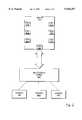
- FIG. 1shows a router 100 that includes ports 101-107, each of which is coupled to a different network.
- a number of physically distinct networksare shown and include a network 110 having logical networks A and B defined therein, a Fiber Distributed Data Interface (FDDI) network 115, an Ethernet network 120, an Asynchronous Transfer Mode (ATM) network 125, a Wide Area Network (WAN) 130, and a Token Ring Network 135.
- FDDIFiber Distributed Data Interface
- ATMAsynchronous Transfer Mode
- WANWide Area Network
- the number of ports that may be provided for a single routeris limited by many practical considerations. Therefore, it would be desirable for providing a mechanism that allows for a reduction in the number of ports required to interconnect a multiplicity of distinct networks. In this manner, a single router may be used to interconnect more distinct networks than is practicable using prior art schemes.
- the routergenerally comprises a physical interface (port) that is coupled to a plurality of distinct networks.
- a multiplexing fabricis provided to couple the distinct networks to the port.
- the routeralso includes a routing engine. When an internetwork packet is received from a first network via the port, the router determines how to route the internetwork packet. If the routing engine determines that the best route for the internetwork packet is via the port from which it was received, the routing engine routes the packet via that port. In this manner, the router routes internetwork traffic between distinct networks using a single physical interface.
- the multiplexing fabricis used to provide distinct communications channels for each of the connected networks.
- the multiplexing fabricis provided by using a networking protocol such as ATM or FDDI. Internetwork packets are encapsulated using the networking protocol of the multiplexing fabric and forwarded to the router for processing.
- the multiplexing fabricmay be used to provide distinct communications channels for networks that operate according to a multiplicity of different networking protocols.
- FIG. 1shows a network router that operates according to the prior art.
- FIG. 2shows a network router having a multiplexed port that operates according to a present embodiment.
- FIG. 3shows a general method of operation for the network router shown in FIG. 2.
- FIG. 4shows a network router of one embodiment wherein the multiplexing fabric is a switched fabric.
- FIG. 5shows a network router of one embodiment wherein the multiplexing fabric is a shared media fabric.
- FIG. 2shows an arrangement wherein a router may route data packets between distinct networks coupled to the same physical interface. More specifically, FIG. 2 shows a router 200, a multiplexing fabric 210, and a plurality of distinct networks 215, 220, and 225 wherein each network 215, 220, and 225 has a unique network ID or address.
- Router 200includes a plurality of ports 201-207, wherein port 201 operates as a multiplexed port for receiving and transmitting data packets from the plurality of networks coupled via multiplexing fabric 210.
- each of the remaining ports 202-207may be single network ports or multiplexed ports for coupling router 200 to other networks.
- Multiplexing fabric 210is connected to multiplexed port 201 and to networks 215, 220, and 225 for carrying internetwork traffic for all of the connected networks.
- the terms "internetwork traffic” and “internetwork packet”will be understood to refer to network traffic sent between distinct networks.
- Multiplexing fabric 210provides distinct communications channels for each of the connected networks such that each network only receives internetwork traffic destined for that network.
- a "communications channel”does not require a distinct point-to-point link and may be provided in a number of different ways.
- Multiplexing fabric 210multiplexes the internetwork traffic of the connected networks such that router 200 receives the internetwork traffic of all of the connected networks via the same port 201.
- Router 200determines the destination network (or networks) of internetwork packets received from port 201 and routes the internetwork packets appropriately. If router 200 determines that the destination network is coupled to router 200 via port 201, router 200 routes the internetwork packet via port 201. In this manner, router 200 routes data between distinct networks coupled to the same interface.
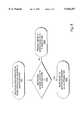
- FIG. 3shows a general method used by router 200 to route internetwork data packets received via a multiplexed port.
- router 200receives an internetwork packet from one of the networks connected to multiplexing fabric 210.
- router 200determines the best route to the destination network. If the best route to the destination network is via another port, router 200 processes the internetwork packet appropriately and routes it through that port at process block 303. If the destination network is coupled to multiplexed port 201 or if the best route to the destination network is through multiplexed port 201, router 200 processes the internetwork data packet appropriately and routes it via multiplexed port 201 at process block 304.
- multiplexing fabric 210may be implemented in a number of equivalent ways.
- multiplexing fabric 210may be implemented as a central hardware resource or in a distributed manner wherein the functionality of multiplexing fabric 210 is distributed between the router the connected networks.
- multiplexing fabric 210may be provided in a circuit switched manner or by using a packet switched network protocol.
- multiplexing fabric 210is achieved by encapsulating internetwork packets using the data link layer protocol of a high bandwidth network type.
- multiplexing fabric 210may be provided by using the switched media of ATM or the shared media of FDDI or 100 Mbps Ethernet. Multiplexing fabric 210 may therefore be used to interconnect a number of lower bandwidth networks to the same physical interface.
- multiplexing fabric 210should be able to support the full bandwidth of the connected networks. For example, if 100 Mbps Ethernet is used as the multiplexing fabric, a maximum of ten 10 Mbps Ethernet should be connected for the multiplexing fabric. Wherein multiplexing fabric is a switched media, bandwidth oversubscription may be supported.
- router 200In order to ensure appropriate translation of data packets routed between different network types, a mechanism is needed to allow the router to discriminate between internetwork packets received via multiplexed port 201.
- One simple mechanismis to define a distinct communications channel for each network connected to multiplexed port 201 and to associate a specific network type for each connected network. In this manner, router 200 is able to determine what processing is needed simply by referring to the network types of the source and destination networks as indicated by the communications channels from which the internetwork packet is received and over which the internetwork packet is to be transmitted.
- TDMtime division multiplexing
- FDMfrequency division multiplexing
- Other alternativesinclude, but are not limited to, the following: defining a unique address space for each communications channel; defining a unique channel identifier for inclusion in the header of internetwork packets; and defining a unique virtual channel (VC) for each communications channel.
- VCvirtual channel
- Defining a unique virtual channel for each communications channel of the multiplexing fabricis a relatively straightforward process when the multiplexing fabric operates according to an ATM protocol.
- FIG. 4shows an arrangement wherein a switched multiplexing fabric is used to provide distinct communications channels for each of the networks connected to the multiplexed port.
- switched multiplexing fabric 405comprises an ATM link 407, which may be, for example, a T1 line, an E1 line, or an OC3 line.
- ATM link 407which may be, for example, a T1 line, an E1 line, or an OC3 line.
- Each of the connected networks 410, 415, and 420includes an ATM interface (“ATM IF") that provides the physical interface to ATM link 407 as well as a number of services for accomplishing data transfer via ATM link 407.
- ATM IFATM interface
- the ATM interfaceincludes a segmentation and reassembly (SAR) unit (not shown) for segmenting internetwork packets into cells for transmission to router 200 and for reassembling cells received from router 200 into internetwork packets for transmission to the connected network.
- SARsegmentation and reassembly
- each ATM interfaceis provided with a SAR unit that most efficiently segments and reassembles packets for that network type.
- each network 410, 415, and 420may be provided in any convenient manner.
- the ATM interface of each networkmay be provided in an internetworking device such as a router or repeater of that network.
- a repeatermay be interposed between the networks and ATM link 407 for providing a single ATM interface for all of the connected networks.
- each connected network 410, 415, and 420would be connected to the repeater via a port compatible with its network type, and the repeater would include a fourth port for coupling to ATM link 407. Both of these alternatives are logically equivalent.
- each communications channelis defined by a distinct VC.
- network 410is coupled to router 200 via a first virtual channel VC1
- network 415is coupled to router 200 via second virtual channel VC2
- network 420is coupled to router 200 via third and fourth virtual channels VC3 and VC4 wherein VC3 is provided as the communications channel for a logical network A, and VC4 is provided as the communications channel for a logical network B.
- the router of FIG. 4is shown as including a multiplexed port module 400 for controlling the routing of internetwork packets received via the multiplexed port and switched multiplexing fabric 405.
- Multiplexed port module 400is shown as generally comprising an ATM interface 425 and a routing engine 430.
- multiplexing port modulemay only include ATM interface 425 and forward reassembled internetwork packets to a central routing engine used by all ports of the router.
- ATM interface 425is typically more complicated than the ATM interfaces of the connected networks because ATM interface 425 must segment and reassemble internetwork packets received from different network types.
- ATM interface 425may therefore be provided with a multiplicity of SAR units, one for each VC, but the same functionality may be achieved using a common SAR unit that executes different SAR programs for each identified network type.
- ATM interface 425When ATM interface 425 receives and reassembles an internetwork packet from a multiplexed port, ATM interface 425 forwards the reassembled internetwork packet to routing engine 430 via receive path 435. Routing engine 430 determines the network address of the destination network. If the network address of the destination network indicates that the internetwork packet should be routed via another port of the router, routing engine 430 forwards the internetwork packet to the associated port module of that port. If the network address of the destination network indicates that the internetwork packet should be routed via the multiplexed port, routing engine performs any necessary protocol translation and forwards the internetwork packet to ATM interface 425 via transmit path 440. ATM interface segments the internetwork packet and forwards the segmented packet to the destination network via the appropriate VC.
- network 410may be an Ethernet LAN that has internetwork traffic bound for network 415, which may be a Token Ring LAN.
- the ATM interface of network 410segments Ethernet packets into cells for transmission over VC1.
- Each of the Ethernet packetsincludes a destination network address indicating the network address of network 415.
- Each of the cells transmitted by network 410include Virtual Path Identifier (VPI) and Virtual Channel Identifier (VCI) fields that indicate transmission over VC1.
- VPNVirtual Path Identifier
- VCIVirtual Channel Identifier
- ATM interface 425 of multiplexed port module 400receives and resegments the Ethernet packets and forwards them to routing engine 430. Routing engine 430 checks the destination network address and determines that the internetwork packets must be translated from the Ethernet protocol to the Token Ring protocol.
- Routing engine 430performs the necessary processing and forwards the internetwork packets to ATM interface 425.
- ATM interface 425segments the internetwork packets into ATM cells having VPI and VCI fields that indicate transmission over VC2.
- ATM interface 425may determine the correct virtual channel number based on the destination network address, or routing engine 430 may inform ATM interface 425 of the correct virtual channel number.
- ATM interface 425then forwards the internetwork packets as cells via VC2 to network 415.
- the ATM interface of network 415reassembles the internetwork packets, which are allowed to propagate to the indicated host or hosts of network 415.
- FIG. 5shows an alternative networking arrangement wherein the multiplexing fabric uses a shared medium for multiplexing internetwork packets.
- Shared media multiplexing fabric 505is shown as comprising an FDDI ring 507 to which each of the networks 510 and 515 and logical networks A and B are coupled as hosts.
- the router of FIG. 5further shows that the multiplexed port module 500 is also coupled to FDDI ring 507 as a host.
- Each of the networksis provided with a media access controller ("MAC") for interfacing to FDDI ring 507.
- the media access controllers of the connected networksare provided with the appropriate facilities for encapsulating internetwork packets in standard FDDI packets.
- Media access controller 525 of multiplexed port module 500is provided with the appropriate facilities for encapsulating and decapsulating internetwork packets of various network types. Decapsulated internetwork packets are transferred to routing engine 530 via receive path 535, and routing engine 530 transfers internetwork packets for encapsulation by media access controller 525 via transmit path 540.
- Each media access controllers of the networks and the multiplexed port moduleare each provided with a unique MAC address. To ensure security, the networks are not allowed to communicate directly with one another via the shared media multiplexing fabric. Instead, all encapsulated internetwork packets are forwarded to the router, which processes decapsulated packets and forwards them to the MAC address that corresponds to the network address of the destination network.
Landscapes
- Engineering & Computer Science (AREA)
- Computer Networks & Wireless Communication (AREA)
- Signal Processing (AREA)
- Data Exchanges In Wide-Area Networks (AREA)
Abstract
Description
Claims (16)
Priority Applications (1)
| Application Number | Priority Date | Filing Date | Title |
|---|---|---|---|
| US08/591,891US5930257A (en) | 1996-01-25 | 1996-01-25 | Network router that routes internetwork packets between distinct networks coupled to the same physical interface using the physical interface |
Applications Claiming Priority (1)
| Application Number | Priority Date | Filing Date | Title |
|---|---|---|---|
| US08/591,891US5930257A (en) | 1996-01-25 | 1996-01-25 | Network router that routes internetwork packets between distinct networks coupled to the same physical interface using the physical interface |
Publications (1)
| Publication Number | Publication Date |
|---|---|
| US5930257Atrue US5930257A (en) | 1999-07-27 |
Family
ID=24368385
Family Applications (1)
| Application Number | Title | Priority Date | Filing Date |
|---|---|---|---|
| US08/591,891Expired - LifetimeUS5930257A (en) | 1996-01-25 | 1996-01-25 | Network router that routes internetwork packets between distinct networks coupled to the same physical interface using the physical interface |
Country Status (1)
| Country | Link |
|---|---|
| US (1) | US5930257A (en) |
Cited By (32)
| Publication number | Priority date | Publication date | Assignee | Title |
|---|---|---|---|---|
| US6061368A (en)* | 1997-11-05 | 2000-05-09 | Xylan Corporation | Custom circuitry for adaptive hardware routing engine |
| US6108345A (en)* | 1997-05-30 | 2000-08-22 | 3Com Corporation | Configurable Wan/Lan bridge |
| US6175867B1 (en)* | 1998-03-23 | 2001-01-16 | Mci World Com, Inc. | System and method for managing networks addressed via common network addresses |
| WO2001047190A1 (en)* | 1999-12-22 | 2001-06-28 | Mci Worldcom, Inc. | Method, computer program product, and apparatus for collecting service level agreement statistics in a communication network |
| US6269101B1 (en)* | 1997-12-31 | 2001-07-31 | At&T Corporation | Network server platform for a hybrid fiber twisted pair local loop network service architecture |
| US20010043604A1 (en)* | 1997-04-25 | 2001-11-22 | Northern Telecom Limited. | Method and apparatus for ATM address resolution |
| US6356546B1 (en)* | 1998-08-11 | 2002-03-12 | Nortel Networks Limited | Universal transfer method and network with distributed switch |
| US6385171B1 (en)* | 1996-09-03 | 2002-05-07 | Hitachi, Ltd. | Router apparatus using ATM switch |
| US20020165982A1 (en)* | 2001-04-18 | 2002-11-07 | Jerrold Leichter | Implementing managed network services for customers with duplicate IP networks |
| US6510151B1 (en)* | 1996-09-19 | 2003-01-21 | Enterasys Networks, Inc. | Packet filtering in connection-based switching networks |
| US6546016B1 (en) | 1997-12-31 | 2003-04-08 | At&T Corp. | Coaxial cable/twisted pair cable telecommunications network architecture |
| US20030163625A1 (en)* | 2002-02-22 | 2003-08-28 | Broadcom Corporation | Switch architecture independent of media |
| US6614794B1 (en)* | 1999-03-03 | 2003-09-02 | Conexant Systems, Inc. | System and method for multiple modem traffic redirection |
| US20030210704A1 (en)* | 2002-05-10 | 2003-11-13 | Yung-Chieg Tung | Very high data rate digital subscriber line modem |
| US6650646B1 (en)* | 1994-01-21 | 2003-11-18 | Alcatel Canada Inc. | Digital communications system |
| WO2004019146A1 (en)* | 2002-08-16 | 2004-03-04 | Endress + Hauser Gmbh + Co. Kg | Device for transmitting, exchanging and/or routing data and/or information |
| US20040131064A1 (en)* | 1994-01-21 | 2004-07-08 | Alcatel Canada Inc. | Digital communications system |
| US20040148521A1 (en)* | 2002-05-13 | 2004-07-29 | Sandia National Laboratories | Method and apparatus for invisible network responder |
| US20040162994A1 (en)* | 2002-05-13 | 2004-08-19 | Sandia National Laboratories | Method and apparatus for configurable communication network defenses |
| US20050086385A1 (en)* | 2003-10-20 | 2005-04-21 | Gordon Rouleau | Passive connection backup |
| US20060007945A1 (en)* | 2002-03-11 | 2006-01-12 | Roland Schoettle | Medium to disparate medium hopping mesh network |
| US7039687B1 (en)* | 1998-08-07 | 2006-05-02 | Nortel Networks Limited | Multi-protocol label switching virtual private networks |
| US20070030832A1 (en)* | 2005-08-08 | 2007-02-08 | Honeywell International Inc. | Integrated infrastructure supporting multiple wireless devices |
| US20070179992A1 (en)* | 1998-05-13 | 2007-08-02 | Lynch Thomas W | Maintaining coherency in a symbiotic computing system and method of operation thereof |
| US20090058185A1 (en)* | 2007-08-31 | 2009-03-05 | Optimal Innovations Inc. | Intelligent Infrastructure Power Supply Control System |
| US7567511B1 (en) | 2006-05-10 | 2009-07-28 | At&T Intellectual Property Ii, L.P. | Method and apparatus for computing the cost of providing VPN service |
| US7573891B1 (en) | 2001-12-05 | 2009-08-11 | Optimal Innovations, Inc. | Hybrid fiber/conductor integrated communication networks |
| US20090271615A1 (en)* | 2007-11-07 | 2009-10-29 | Meidensha Corporation | Bridging system, bridge, and bridging method |
| US20120250685A1 (en)* | 2006-07-28 | 2012-10-04 | Internatonal Business Machines Corporation | Forwarding groups of multicast flows |
| US8612711B1 (en)* | 2009-09-21 | 2013-12-17 | Tilera Corporation | Memory-mapped data transfers |
| US9084291B1 (en)* | 1996-12-16 | 2015-07-14 | Ip Holdings, Inc. | Interfacing internet protocol-based wireless devices with networks |
| RU2619694C1 (en)* | 2013-06-25 | 2017-05-17 | Гугл Инк. | Effective communication for home network devices |
Citations (4)
| Publication number | Priority date | Publication date | Assignee | Title |
|---|---|---|---|---|
| US5210748A (en)* | 1990-02-09 | 1993-05-11 | Hitachi, Ltd. | Address filter unit for carrying out address filter processing among plurality of networks and method thereof |
| US5423002A (en)* | 1992-04-20 | 1995-06-06 | 3Com Corporation | System for extending network resources to remote networks |
| US5434863A (en)* | 1991-08-30 | 1995-07-18 | Hitachi, Ltd. | Internetworking apparatus for connecting plural network systems and communication network system composed of plural network systems mutually connected |
| US5600644A (en)* | 1995-03-10 | 1997-02-04 | At&T | Method and apparatus for interconnecting LANs |
- 1996
- 1996-01-25USUS08/591,891patent/US5930257A/ennot_activeExpired - Lifetime
Patent Citations (4)
| Publication number | Priority date | Publication date | Assignee | Title |
|---|---|---|---|---|
| US5210748A (en)* | 1990-02-09 | 1993-05-11 | Hitachi, Ltd. | Address filter unit for carrying out address filter processing among plurality of networks and method thereof |
| US5434863A (en)* | 1991-08-30 | 1995-07-18 | Hitachi, Ltd. | Internetworking apparatus for connecting plural network systems and communication network system composed of plural network systems mutually connected |
| US5423002A (en)* | 1992-04-20 | 1995-06-06 | 3Com Corporation | System for extending network resources to remote networks |
| US5600644A (en)* | 1995-03-10 | 1997-02-04 | At&T | Method and apparatus for interconnecting LANs |
Non-Patent Citations (2)
| Title |
|---|
| Newton, Harry, "Newton's Telecom Dictionary", 9th Edition, pp. 978-979, 1995. |
| Newton, Harry, Newton s Telecom Dictionary , 9th Edition, pp. 978 979, 1995.* |
Cited By (49)
| Publication number | Priority date | Publication date | Assignee | Title |
|---|---|---|---|---|
| US20040131064A1 (en)* | 1994-01-21 | 2004-07-08 | Alcatel Canada Inc. | Digital communications system |
| US7327688B2 (en) | 1994-01-21 | 2008-02-05 | Alcatel Canada Inc. | Digital communications system |
| US6650646B1 (en)* | 1994-01-21 | 2003-11-18 | Alcatel Canada Inc. | Digital communications system |
| US6385171B1 (en)* | 1996-09-03 | 2002-05-07 | Hitachi, Ltd. | Router apparatus using ATM switch |
| US6510151B1 (en)* | 1996-09-19 | 2003-01-21 | Enterasys Networks, Inc. | Packet filtering in connection-based switching networks |
| US9084291B1 (en)* | 1996-12-16 | 2015-07-14 | Ip Holdings, Inc. | Interfacing internet protocol-based wireless devices with networks |
| US7075931B2 (en)* | 1997-04-25 | 2006-07-11 | Nortel Networks Limited | Method and apparatus for ATM address resolution |
| US20010043604A1 (en)* | 1997-04-25 | 2001-11-22 | Northern Telecom Limited. | Method and apparatus for ATM address resolution |
| US6108345A (en)* | 1997-05-30 | 2000-08-22 | 3Com Corporation | Configurable Wan/Lan bridge |
| US6061368A (en)* | 1997-11-05 | 2000-05-09 | Xylan Corporation | Custom circuitry for adaptive hardware routing engine |
| US6546016B1 (en) | 1997-12-31 | 2003-04-08 | At&T Corp. | Coaxial cable/twisted pair cable telecommunications network architecture |
| US6269101B1 (en)* | 1997-12-31 | 2001-07-31 | At&T Corporation | Network server platform for a hybrid fiber twisted pair local loop network service architecture |
| US6175867B1 (en)* | 1998-03-23 | 2001-01-16 | Mci World Com, Inc. | System and method for managing networks addressed via common network addresses |
| US20070179992A1 (en)* | 1998-05-13 | 2007-08-02 | Lynch Thomas W | Maintaining coherency in a symbiotic computing system and method of operation thereof |
| US7039687B1 (en)* | 1998-08-07 | 2006-05-02 | Nortel Networks Limited | Multi-protocol label switching virtual private networks |
| US6356546B1 (en)* | 1998-08-11 | 2002-03-12 | Nortel Networks Limited | Universal transfer method and network with distributed switch |
| US7061910B2 (en)* | 1998-08-11 | 2006-06-13 | Nortel Networks Limited | Universal transfer method and network with distributed switch |
| US20020080790A1 (en)* | 1998-08-11 | 2002-06-27 | Beshai Maged E. | Universal transfer method and network with distributed switch |
| US6614794B1 (en)* | 1999-03-03 | 2003-09-02 | Conexant Systems, Inc. | System and method for multiple modem traffic redirection |
| WO2001047190A1 (en)* | 1999-12-22 | 2001-06-28 | Mci Worldcom, Inc. | Method, computer program product, and apparatus for collecting service level agreement statistics in a communication network |
| US6366563B1 (en)* | 1999-12-22 | 2002-04-02 | Mci Worldcom, Inc. | Method, computer program product, and apparatus for collecting service level agreement statistics in a communication network |
| US7383357B2 (en) | 2001-04-18 | 2008-06-03 | Emc Corporation | Implementing managed network services for customers with duplicate IP networks |
| US20020165982A1 (en)* | 2001-04-18 | 2002-11-07 | Jerrold Leichter | Implementing managed network services for customers with duplicate IP networks |
| US7573891B1 (en) | 2001-12-05 | 2009-08-11 | Optimal Innovations, Inc. | Hybrid fiber/conductor integrated communication networks |
| US20050268017A1 (en)* | 2002-02-22 | 2005-12-01 | Broadcom Corporation | Method of handling data in a network device |
| EP1341348A1 (en)* | 2002-02-22 | 2003-09-03 | Broadcom Corporation | Switch architecture independent of type of media |
| US6934787B2 (en) | 2002-02-22 | 2005-08-23 | Broadcom Corporation | Adaptable switch architecture that is independent of media types |
| US7054977B2 (en) | 2002-02-22 | 2006-05-30 | Broadcom Corporation | Method of handling data in a network device |
| US7725639B2 (en) | 2002-02-22 | 2010-05-25 | Broadcom Corporation | Switch architecture independent of media |
| US20090138644A1 (en)* | 2002-02-22 | 2009-05-28 | Broadcom Corporation | Switch architecture independent of media |
| US20060184712A1 (en)* | 2002-02-22 | 2006-08-17 | Broadcom Corporation | Switch architecture independent of media |
| US20030163625A1 (en)* | 2002-02-22 | 2003-08-28 | Broadcom Corporation | Switch architecture independent of media |
| US7469310B2 (en) | 2002-02-22 | 2008-12-23 | Broadcom Corporation | Network switch architecture for processing packets independent of media type of connected ports |
| US20060007945A1 (en)* | 2002-03-11 | 2006-01-12 | Roland Schoettle | Medium to disparate medium hopping mesh network |
| US20030210704A1 (en)* | 2002-05-10 | 2003-11-13 | Yung-Chieg Tung | Very high data rate digital subscriber line modem |
| US20040148521A1 (en)* | 2002-05-13 | 2004-07-29 | Sandia National Laboratories | Method and apparatus for invisible network responder |
| US20040162994A1 (en)* | 2002-05-13 | 2004-08-19 | Sandia National Laboratories | Method and apparatus for configurable communication network defenses |
| WO2004019146A1 (en)* | 2002-08-16 | 2004-03-04 | Endress + Hauser Gmbh + Co. Kg | Device for transmitting, exchanging and/or routing data and/or information |
| US20050086385A1 (en)* | 2003-10-20 | 2005-04-21 | Gordon Rouleau | Passive connection backup |
| US20070030832A1 (en)* | 2005-08-08 | 2007-02-08 | Honeywell International Inc. | Integrated infrastructure supporting multiple wireless devices |
| US7801094B2 (en)* | 2005-08-08 | 2010-09-21 | Honeywell International Inc. | Integrated infrastructure supporting multiple wireless devices |
| US7567511B1 (en) | 2006-05-10 | 2009-07-28 | At&T Intellectual Property Ii, L.P. | Method and apparatus for computing the cost of providing VPN service |
| US20120250685A1 (en)* | 2006-07-28 | 2012-10-04 | Internatonal Business Machines Corporation | Forwarding groups of multicast flows |
| US9385936B2 (en)* | 2006-07-28 | 2016-07-05 | International Business Machines Corporation | Forwarding groups of multicast flows |
| US20090058185A1 (en)* | 2007-08-31 | 2009-03-05 | Optimal Innovations Inc. | Intelligent Infrastructure Power Supply Control System |
| US20090271615A1 (en)* | 2007-11-07 | 2009-10-29 | Meidensha Corporation | Bridging system, bridge, and bridging method |
| US8880870B2 (en)* | 2007-11-07 | 2014-11-04 | Meidensha Corporation | Bridging system, bridge, and bridging method |
| US8612711B1 (en)* | 2009-09-21 | 2013-12-17 | Tilera Corporation | Memory-mapped data transfers |
| RU2619694C1 (en)* | 2013-06-25 | 2017-05-17 | Гугл Инк. | Effective communication for home network devices |
Similar Documents
| Publication | Publication Date | Title |
|---|---|---|
| US5930257A (en) | Network router that routes internetwork packets between distinct networks coupled to the same physical interface using the physical interface | |
| EP1393192B1 (en) | Method and system for connecting virtual circuits across an ethernet switch | |
| US7983281B2 (en) | VPN composing method, interwork router, packet communication method, data communication apparatus, and packet relaying apparatus | |
| US5732080A (en) | Method and apparatus for controlling data flow within a switching device | |
| US5408469A (en) | Routing device utilizing an ATM switch as a multi-channel backplane in a communication network | |
| EP0923210B1 (en) | Transparent interconnection of LANs by an ATM network | |
| US5852606A (en) | Method and apparatus for transmitting cells across an ATM switch bus | |
| US7327688B2 (en) | Digital communications system | |
| US6757298B1 (en) | VLAN trunking over ATM PVCs (VTAP) | |
| US5737334A (en) | Pipeline architecture for an ATM switch backplane bus | |
| EP1475942A2 (en) | Address Resolution in IP Internetworking Layer 2 point-to-point connections | |
| US20030152182A1 (en) | Optical exchange method, apparatus and system for facilitating data transport between WAN, SAN and LAN and for enabling enterprise computing into networks | |
| US8064465B2 (en) | Packet forwarding apparatus | |
| JPH0799830B2 (en) | Communication protocol for a statistical data multiplexer incorporated in a wide area network. | |
| US6718419B1 (en) | System and method for extending the number of addressable physical devices on a data bus | |
| WO1992017014A1 (en) | Connectionless switching for an atm switch | |
| WO2000056113A1 (en) | Internet protocol switch and method | |
| JP2001268113A (en) | Label request packet transmitting method, and network, method and device for packet transfer | |
| EP1548964B1 (en) | Network-based data distribution system | |
| JP2002503056A (en) | Virtual Star Network | |
| US7145916B2 (en) | Full multicast connectivity over SONET | |
| Cisco | Introduction to LightStream 2020 | |
| Cisco | Introduction to LightStream 2020 | |
| Cisco | Introduction to LightStream 2020 | |
| JP3715541B2 (en) | ATM connection device |
Legal Events
| Date | Code | Title | Description |
|---|---|---|---|
| AS | Assignment | Owner name:BAY NETWORKS, INC., MASSACHUSETTS Free format text:ASSIGNMENT OF ASSIGNORS INTEREST;ASSIGNORS:SMITH, ANDREW;WALDFOGEL, ASHER;REEL/FRAME:007920/0367 Effective date:19960410 | |
| STCF | Information on status: patent grant | Free format text:PATENTED CASE | |
| AS | Assignment | Owner name:NORTEL NETWORKS NA INC., CALIFORNIA Free format text:CHANGE OF NAME;ASSIGNOR:BAY NETWORKS, INC.;REEL/FRAME:010461/0283 Effective date:19990430 | |
| AS | Assignment | Owner name:NORTEL NETWORKS CORPORATION, CANADA Free format text:ASSIGNMENT OF ASSIGNORS INTEREST;ASSIGNOR:NORTEL NETWORKS NA INC.;REEL/FRAME:010547/0891 Effective date:19991229 | |
| AS | Assignment | Owner name:NORTEL NETWORKS CORPORATION, CANADA Free format text:ASSIGNMENT OF ASSIGNORS INTEREST;ASSIGNOR:WILLIS, STEVEN R.;REEL/FRAME:010785/0060 Effective date:20000424 | |
| AS | Assignment | Owner name:NORTEL NETWORKS LIMITED, CANADA Free format text:CHANGE OF NAME;ASSIGNOR:NORTEL NETWORKS CORPORATION;REEL/FRAME:011195/0706 Effective date:20000830 Owner name:NORTEL NETWORKS LIMITED,CANADA Free format text:CHANGE OF NAME;ASSIGNOR:NORTEL NETWORKS CORPORATION;REEL/FRAME:011195/0706 Effective date:20000830 | |
| CC | Certificate of correction | ||
| FEPP | Fee payment procedure | Free format text:PAT HOLDER NO LONGER CLAIMS SMALL ENTITY STATUS, ENTITY STATUS SET TO UNDISCOUNTED (ORIGINAL EVENT CODE: STOL); ENTITY STATUS OF PATENT OWNER: LARGE ENTITY | |
| REFU | Refund | Free format text:REFUND - SURCHARGE, PETITION TO ACCEPT PYMT AFTER EXP, UNINTENTIONAL (ORIGINAL EVENT CODE: R2551); ENTITY STATUS OF PATENT OWNER: LARGE ENTITY | |
| FEPP | Fee payment procedure | Free format text:PAYOR NUMBER ASSIGNED (ORIGINAL EVENT CODE: ASPN); ENTITY STATUS OF PATENT OWNER: LARGE ENTITY | |
| FPAY | Fee payment | Year of fee payment:4 | |
| FPAY | Fee payment | Year of fee payment:8 | |
| FEPP | Fee payment procedure | Free format text:PAYOR NUMBER ASSIGNED (ORIGINAL EVENT CODE: ASPN); ENTITY STATUS OF PATENT OWNER: LARGE ENTITY Free format text:PAYER NUMBER DE-ASSIGNED (ORIGINAL EVENT CODE: RMPN); ENTITY STATUS OF PATENT OWNER: LARGE ENTITY | |
| AS | Assignment | Owner name:CITIBANK, N.A., AS ADMINISTRATIVE AGENT,NEW YORK Free format text:SECURITY AGREEMENT;ASSIGNOR:AVAYA INC.;REEL/FRAME:023892/0500 Effective date:20100129 Owner name:CITIBANK, N.A., AS ADMINISTRATIVE AGENT, NEW YORK Free format text:SECURITY AGREEMENT;ASSIGNOR:AVAYA INC.;REEL/FRAME:023892/0500 Effective date:20100129 | |
| AS | Assignment | Owner name:CITICORP USA, INC., AS ADMINISTRATIVE AGENT, NEW YORK Free format text:SECURITY AGREEMENT;ASSIGNOR:AVAYA INC.;REEL/FRAME:023905/0001 Effective date:20100129 Owner name:CITICORP USA, INC., AS ADMINISTRATIVE AGENT,NEW YO Free format text:SECURITY AGREEMENT;ASSIGNOR:AVAYA INC.;REEL/FRAME:023905/0001 Effective date:20100129 Owner name:CITICORP USA, INC., AS ADMINISTRATIVE AGENT, NEW Y Free format text:SECURITY AGREEMENT;ASSIGNOR:AVAYA INC.;REEL/FRAME:023905/0001 Effective date:20100129 | |
| AS | Assignment | Owner name:AVAYA INC.,NEW JERSEY Free format text:ASSIGNMENT OF ASSIGNORS INTEREST;ASSIGNOR:NORTEL NETWORKS LIMITED;REEL/FRAME:023998/0878 Effective date:20091218 Owner name:AVAYA INC., NEW JERSEY Free format text:ASSIGNMENT OF ASSIGNORS INTEREST;ASSIGNOR:NORTEL NETWORKS LIMITED;REEL/FRAME:023998/0878 Effective date:20091218 | |
| FPAY | Fee payment | Year of fee payment:12 | |
| AS | Assignment | Owner name:BANK OF NEW YORK MELLON TRUST, NA, AS NOTES COLLAT Free format text:SECURITY AGREEMENT;ASSIGNOR:AVAYA INC., A DELAWARE CORPORATION;REEL/FRAME:025863/0535 Effective date:20110211 Owner name:BANK OF NEW YORK MELLON TRUST, NA, AS NOTES COLLATERAL AGENT, THE, PENNSYLVANIA Free format text:SECURITY AGREEMENT;ASSIGNOR:AVAYA INC., A DELAWARE CORPORATION;REEL/FRAME:025863/0535 Effective date:20110211 | |
| AS | Assignment | Owner name:BANK OF NEW YORK MELLON TRUST COMPANY, N.A., THE, PENNSYLVANIA Free format text:SECURITY AGREEMENT;ASSIGNOR:AVAYA, INC.;REEL/FRAME:030083/0639 Effective date:20130307 Owner name:BANK OF NEW YORK MELLON TRUST COMPANY, N.A., THE, Free format text:SECURITY AGREEMENT;ASSIGNOR:AVAYA, INC.;REEL/FRAME:030083/0639 Effective date:20130307 | |
| AS | Assignment | Owner name:AVAYA INC., CALIFORNIA Free format text:BANKRUPTCY COURT ORDER RELEASING ALL LIENS INCLUDING THE SECURITY INTEREST RECORDED AT REEL/FRAME 025863/0535;ASSIGNOR:THE BANK OF NEW YORK MELLON TRUST, NA;REEL/FRAME:044892/0001 Effective date:20171128 Owner name:AVAYA INC., CALIFORNIA Free format text:BANKRUPTCY COURT ORDER RELEASING ALL LIENS INCLUDING THE SECURITY INTEREST RECORDED AT REEL/FRAME 023892/0500;ASSIGNOR:CITIBANK, N.A.;REEL/FRAME:044891/0564 Effective date:20171128 Owner name:AVAYA INC., CALIFORNIA Free format text:BANKRUPTCY COURT ORDER RELEASING ALL LIENS INCLUDING THE SECURITY INTEREST RECORDED AT REEL/FRAME 030083/0639;ASSIGNOR:THE BANK OF NEW YORK MELLON TRUST COMPANY, N.A.;REEL/FRAME:045012/0666 Effective date:20171128 | |
| AS | Assignment | Owner name:AVAYA, INC., CALIFORNIA Free format text:RELEASE BY SECURED PARTY;ASSIGNOR:CITICORP USA, INC.;REEL/FRAME:045045/0564 Effective date:20171215 Owner name:SIERRA HOLDINGS CORP., NEW JERSEY Free format text:RELEASE BY SECURED PARTY;ASSIGNOR:CITICORP USA, INC.;REEL/FRAME:045045/0564 Effective date:20171215 |