US5930030A - Apparatus for pumping an optical gain medium with multiple light wavelengths - Google Patents
Apparatus for pumping an optical gain medium with multiple light wavelengthsDownload PDFInfo
- Publication number
- US5930030A US5930030AUS09/126,119US12611998AUS5930030AUS 5930030 AUS5930030 AUS 5930030AUS 12611998 AUS12611998 AUS 12611998AUS 5930030 AUS5930030 AUS 5930030A
- Authority
- US
- United States
- Prior art keywords
- fiber
- amplifier
- pump
- source
- gain medium
- Prior art date
- Legal status (The legal status is an assumption and is not a legal conclusion. Google has not performed a legal analysis and makes no representation as to the accuracy of the status listed.)
- Expired - Lifetime
Links
- 238000005086pumpingMethods0.000titleclaimsabstractdescription57
- 230000003287optical effectEffects0.000titleclaimsabstractdescription54
- 239000000835fiberSubstances0.000claimsabstractdescription260
- 238000010521absorption reactionMethods0.000claimsabstractdescription22
- 238000001228spectrumMethods0.000claimsabstractdescription16
- 238000002347injectionMethods0.000claimsdescription83
- 239000007924injectionSubstances0.000claimsdescription83
- 239000013307optical fiberSubstances0.000claimsdescription32
- 238000005253claddingMethods0.000claimsdescription31
- 238000010168coupling processMethods0.000claimsdescription29
- 238000005859coupling reactionMethods0.000claimsdescription29
- 230000008878couplingEffects0.000claimsdescription28
- 229910052761rare earth metalInorganic materials0.000claimsdescription27
- 150000002910rare earth metalsChemical class0.000claimsdescription24
- 239000004065semiconductorSubstances0.000claimsdescription14
- 230000005284excitationEffects0.000claimsdescription5
- 239000011162core materialSubstances0.000description35
- 230000003321amplificationEffects0.000description29
- 238000003199nucleic acid amplification methodMethods0.000description29
- 238000013459approachMethods0.000description21
- 239000002019doping agentSubstances0.000description13
- 101100456571Mus musculus Med12 geneProteins0.000description10
- 229910052769YtterbiumInorganic materials0.000description8
- 238000006243chemical reactionMethods0.000description8
- 230000010287polarizationEffects0.000description8
- 238000011084recoveryMethods0.000description8
- 229910052779NeodymiumInorganic materials0.000description7
- 238000000034methodMethods0.000description7
- 230000001360synchronised effectEffects0.000description7
- NAWDYIZEMPQZHO-UHFFFAOYSA-NytterbiumChemical compound[Yb]NAWDYIZEMPQZHO-UHFFFAOYSA-N0.000description7
- 229910052691ErbiumInorganic materials0.000description6
- 238000003491arrayMethods0.000description6
- UYAHIZSMUZPPFV-UHFFFAOYSA-NerbiumChemical compound[Er]UYAHIZSMUZPPFV-UHFFFAOYSA-N0.000description6
- QEFYFXOXNSNQGX-UHFFFAOYSA-Nneodymium atomChemical compound[Nd]QEFYFXOXNSNQGX-UHFFFAOYSA-N0.000description6
- 239000013078crystalSubstances0.000description5
- 238000009738saturatingMethods0.000description5
- 239000006096absorbing agentSubstances0.000description4
- 230000001427coherent effectEffects0.000description4
- 230000008569processEffects0.000description4
- -1rare-earth ionsChemical class0.000description4
- 239000007787solidSubstances0.000description4
- 229910052689HolmiumInorganic materials0.000description3
- 238000000862absorption spectrumMethods0.000description3
- 238000004891communicationMethods0.000description3
- KJZYNXUDTRRSPN-UHFFFAOYSA-Nholmium atomChemical compound[Ho]KJZYNXUDTRRSPN-UHFFFAOYSA-N0.000description3
- 150000002500ionsChemical class0.000description3
- 239000000654additiveSubstances0.000description2
- 230000000996additive effectEffects0.000description2
- 230000005540biological transmissionEffects0.000description2
- 238000010586diagramMethods0.000description2
- 238000012986modificationMethods0.000description2
- 230000004048modificationEffects0.000description2
- 238000007493shaping processMethods0.000description2
- 229910000530Gallium indium arsenideInorganic materials0.000description1
- 229910003334KNbO3Inorganic materials0.000description1
- 229910052777PraseodymiumInorganic materials0.000description1
- VYPSYNLAJGMNEJ-UHFFFAOYSA-NSilicium dioxideChemical compoundO=[Si]=OVYPSYNLAJGMNEJ-UHFFFAOYSA-N0.000description1
- 230000008901benefitEffects0.000description1
- 230000000052comparative effectEffects0.000description1
- 239000002131composite materialSubstances0.000description1
- 239000012141concentrateSubstances0.000description1
- 238000012937correctionMethods0.000description1
- 230000003247decreasing effectEffects0.000description1
- 230000007547defectEffects0.000description1
- 230000001934delayEffects0.000description1
- 238000001514detection methodMethods0.000description1
- 230000009977dual effectEffects0.000description1
- 230000000694effectsEffects0.000description1
- 230000005281excited stateEffects0.000description1
- 239000011521glassSubstances0.000description1
- 239000003365glass fiberSubstances0.000description1
- 238000003384imaging methodMethods0.000description1
- 238000010348incorporationMethods0.000description1
- 230000003993interactionEffects0.000description1
- 238000007648laser printingMethods0.000description1
- 230000007246mechanismEffects0.000description1
- 230000007935neutral effectEffects0.000description1
- 230000010355oscillationEffects0.000description1
- PUDIUYLPXJFUGB-UHFFFAOYSA-Npraseodymium atomChemical compound[Pr]PUDIUYLPXJFUGB-UHFFFAOYSA-N0.000description1
- 238000004321preservationMethods0.000description1
- 238000007639printingMethods0.000description1
- 230000001902propagating effectEffects0.000description1
- 230000003252repetitive effectEffects0.000description1
- 230000004044responseEffects0.000description1
- 229920006395saturated elastomerPolymers0.000description1
- 230000011218segmentationEffects0.000description1
Images


Classifications
- H—ELECTRICITY
- H01—ELECTRIC ELEMENTS
- H01S—DEVICES USING THE PROCESS OF LIGHT AMPLIFICATION BY STIMULATED EMISSION OF RADIATION [LASER] TO AMPLIFY OR GENERATE LIGHT; DEVICES USING STIMULATED EMISSION OF ELECTROMAGNETIC RADIATION IN WAVE RANGES OTHER THAN OPTICAL
- H01S3/00—Lasers, i.e. devices using stimulated emission of electromagnetic radiation in the infrared, visible or ultraviolet wave range
- H01S3/09—Processes or apparatus for excitation, e.g. pumping
- H01S3/091—Processes or apparatus for excitation, e.g. pumping using optical pumping
- H01S3/094—Processes or apparatus for excitation, e.g. pumping using optical pumping by coherent light
- H01S3/094003—Processes or apparatus for excitation, e.g. pumping using optical pumping by coherent light the pumped medium being a fibre
- H—ELECTRICITY
- H01—ELECTRIC ELEMENTS
- H01S—DEVICES USING THE PROCESS OF LIGHT AMPLIFICATION BY STIMULATED EMISSION OF RADIATION [LASER] TO AMPLIFY OR GENERATE LIGHT; DEVICES USING STIMULATED EMISSION OF ELECTROMAGNETIC RADIATION IN WAVE RANGES OTHER THAN OPTICAL
- H01S3/00—Lasers, i.e. devices using stimulated emission of electromagnetic radiation in the infrared, visible or ultraviolet wave range
- H01S3/05—Construction or shape of optical resonators; Accommodation of active medium therein; Shape of active medium
- H01S3/06—Construction or shape of active medium
- H01S3/063—Waveguide lasers, i.e. whereby the dimensions of the waveguide are of the order of the light wavelength
- H01S3/067—Fibre lasers
- H01S3/06754—Fibre amplifiers
- H01S3/06758—Tandem amplifiers
- H—ELECTRICITY
- H01—ELECTRIC ELEMENTS
- H01S—DEVICES USING THE PROCESS OF LIGHT AMPLIFICATION BY STIMULATED EMISSION OF RADIATION [LASER] TO AMPLIFY OR GENERATE LIGHT; DEVICES USING STIMULATED EMISSION OF ELECTROMAGNETIC RADIATION IN WAVE RANGES OTHER THAN OPTICAL
- H01S3/00—Lasers, i.e. devices using stimulated emission of electromagnetic radiation in the infrared, visible or ultraviolet wave range
- H01S3/10—Controlling the intensity, frequency, phase, polarisation or direction of the emitted radiation, e.g. switching, gating, modulating or demodulating
- H01S3/13—Stabilisation of laser output parameters, e.g. frequency or amplitude
- H01S3/1301—Stabilisation of laser output parameters, e.g. frequency or amplitude in optical amplifiers
- H01S3/13013—Stabilisation of laser output parameters, e.g. frequency or amplitude in optical amplifiers by controlling the optical pumping
- H—ELECTRICITY
- H01—ELECTRIC ELEMENTS
- H01S—DEVICES USING THE PROCESS OF LIGHT AMPLIFICATION BY STIMULATED EMISSION OF RADIATION [LASER] TO AMPLIFY OR GENERATE LIGHT; DEVICES USING STIMULATED EMISSION OF ELECTROMAGNETIC RADIATION IN WAVE RANGES OTHER THAN OPTICAL
- H01S2301/00—Functional characteristics
- H01S2301/02—ASE (amplified spontaneous emission), noise; Reduction thereof
- H—ELECTRICITY
- H01—ELECTRIC ELEMENTS
- H01S—DEVICES USING THE PROCESS OF LIGHT AMPLIFICATION BY STIMULATED EMISSION OF RADIATION [LASER] TO AMPLIFY OR GENERATE LIGHT; DEVICES USING STIMULATED EMISSION OF ELECTROMAGNETIC RADIATION IN WAVE RANGES OTHER THAN OPTICAL
- H01S3/00—Lasers, i.e. devices using stimulated emission of electromagnetic radiation in the infrared, visible or ultraviolet wave range
- H01S3/05—Construction or shape of optical resonators; Accommodation of active medium therein; Shape of active medium
- H01S3/06—Construction or shape of active medium
- H01S3/063—Waveguide lasers, i.e. whereby the dimensions of the waveguide are of the order of the light wavelength
- H01S3/067—Fibre lasers
- H01S3/06708—Constructional details of the fibre, e.g. compositions, cross-section, shape or tapering
- H01S3/06729—Peculiar transverse fibre profile
- H—ELECTRICITY
- H01—ELECTRIC ELEMENTS
- H01S—DEVICES USING THE PROCESS OF LIGHT AMPLIFICATION BY STIMULATED EMISSION OF RADIATION [LASER] TO AMPLIFY OR GENERATE LIGHT; DEVICES USING STIMULATED EMISSION OF ELECTROMAGNETIC RADIATION IN WAVE RANGES OTHER THAN OPTICAL
- H01S3/00—Lasers, i.e. devices using stimulated emission of electromagnetic radiation in the infrared, visible or ultraviolet wave range
- H01S3/05—Construction or shape of optical resonators; Accommodation of active medium therein; Shape of active medium
- H01S3/06—Construction or shape of active medium
- H01S3/063—Waveguide lasers, i.e. whereby the dimensions of the waveguide are of the order of the light wavelength
- H01S3/067—Fibre lasers
- H01S3/06754—Fibre amplifiers
- H01S3/06787—Bidirectional amplifier
- H—ELECTRICITY
- H01—ELECTRIC ELEMENTS
- H01S—DEVICES USING THE PROCESS OF LIGHT AMPLIFICATION BY STIMULATED EMISSION OF RADIATION [LASER] TO AMPLIFY OR GENERATE LIGHT; DEVICES USING STIMULATED EMISSION OF ELECTROMAGNETIC RADIATION IN WAVE RANGES OTHER THAN OPTICAL
- H01S3/00—Lasers, i.e. devices using stimulated emission of electromagnetic radiation in the infrared, visible or ultraviolet wave range
- H01S3/09—Processes or apparatus for excitation, e.g. pumping
- H01S3/091—Processes or apparatus for excitation, e.g. pumping using optical pumping
- H01S3/094—Processes or apparatus for excitation, e.g. pumping using optical pumping by coherent light
- H01S3/094026—Processes or apparatus for excitation, e.g. pumping using optical pumping by coherent light for synchronously pumping, e.g. for mode locking
- H—ELECTRICITY
- H01—ELECTRIC ELEMENTS
- H01S—DEVICES USING THE PROCESS OF LIGHT AMPLIFICATION BY STIMULATED EMISSION OF RADIATION [LASER] TO AMPLIFY OR GENERATE LIGHT; DEVICES USING STIMULATED EMISSION OF ELECTROMAGNETIC RADIATION IN WAVE RANGES OTHER THAN OPTICAL
- H01S3/00—Lasers, i.e. devices using stimulated emission of electromagnetic radiation in the infrared, visible or ultraviolet wave range
- H01S3/09—Processes or apparatus for excitation, e.g. pumping
- H01S3/091—Processes or apparatus for excitation, e.g. pumping using optical pumping
- H01S3/094—Processes or apparatus for excitation, e.g. pumping using optical pumping by coherent light
- H01S3/094042—Processes or apparatus for excitation, e.g. pumping using optical pumping by coherent light of a fibre laser
- H—ELECTRICITY
- H01—ELECTRIC ELEMENTS
- H01S—DEVICES USING THE PROCESS OF LIGHT AMPLIFICATION BY STIMULATED EMISSION OF RADIATION [LASER] TO AMPLIFY OR GENERATE LIGHT; DEVICES USING STIMULATED EMISSION OF ELECTROMAGNETIC RADIATION IN WAVE RANGES OTHER THAN OPTICAL
- H01S3/00—Lasers, i.e. devices using stimulated emission of electromagnetic radiation in the infrared, visible or ultraviolet wave range
- H01S3/09—Processes or apparatus for excitation, e.g. pumping
- H01S3/091—Processes or apparatus for excitation, e.g. pumping using optical pumping
- H01S3/094—Processes or apparatus for excitation, e.g. pumping using optical pumping by coherent light
- H01S3/094076—Pulsed or modulated pumping
- H—ELECTRICITY
- H01—ELECTRIC ELEMENTS
- H01S—DEVICES USING THE PROCESS OF LIGHT AMPLIFICATION BY STIMULATED EMISSION OF RADIATION [LASER] TO AMPLIFY OR GENERATE LIGHT; DEVICES USING STIMULATED EMISSION OF ELECTROMAGNETIC RADIATION IN WAVE RANGES OTHER THAN OPTICAL
- H01S3/00—Lasers, i.e. devices using stimulated emission of electromagnetic radiation in the infrared, visible or ultraviolet wave range
- H01S3/09—Processes or apparatus for excitation, e.g. pumping
- H01S3/091—Processes or apparatus for excitation, e.g. pumping using optical pumping
- H01S3/094—Processes or apparatus for excitation, e.g. pumping using optical pumping by coherent light
- H01S3/094096—Multi-wavelength pumping
- H—ELECTRICITY
- H01—ELECTRIC ELEMENTS
- H01S—DEVICES USING THE PROCESS OF LIGHT AMPLIFICATION BY STIMULATED EMISSION OF RADIATION [LASER] TO AMPLIFY OR GENERATE LIGHT; DEVICES USING STIMULATED EMISSION OF ELECTROMAGNETIC RADIATION IN WAVE RANGES OTHER THAN OPTICAL
- H01S3/00—Lasers, i.e. devices using stimulated emission of electromagnetic radiation in the infrared, visible or ultraviolet wave range
- H01S3/09—Processes or apparatus for excitation, e.g. pumping
- H01S3/091—Processes or apparatus for excitation, e.g. pumping using optical pumping
- H01S3/094—Processes or apparatus for excitation, e.g. pumping using optical pumping by coherent light
- H01S3/0941—Processes or apparatus for excitation, e.g. pumping using optical pumping by coherent light of a laser diode
- H01S3/09415—Processes or apparatus for excitation, e.g. pumping using optical pumping by coherent light of a laser diode the pumping beam being parallel to the lasing mode of the pumped medium, e.g. end-pumping
- H—ELECTRICITY
- H01—ELECTRIC ELEMENTS
- H01S—DEVICES USING THE PROCESS OF LIGHT AMPLIFICATION BY STIMULATED EMISSION OF RADIATION [LASER] TO AMPLIFY OR GENERATE LIGHT; DEVICES USING STIMULATED EMISSION OF ELECTROMAGNETIC RADIATION IN WAVE RANGES OTHER THAN OPTICAL
- H01S3/00—Lasers, i.e. devices using stimulated emission of electromagnetic radiation in the infrared, visible or ultraviolet wave range
- H01S3/10—Controlling the intensity, frequency, phase, polarisation or direction of the emitted radiation, e.g. switching, gating, modulating or demodulating
- H01S3/10007—Controlling the intensity, frequency, phase, polarisation or direction of the emitted radiation, e.g. switching, gating, modulating or demodulating in optical amplifiers
- H01S3/1001—Controlling the intensity, frequency, phase, polarisation or direction of the emitted radiation, e.g. switching, gating, modulating or demodulating in optical amplifiers by controlling the optical pumping
Definitions
- the present inventionrelates to optical gain media and, more particularly, to solid state gain media such as an optical fiber amplifier.
- solid state gain mediumis in reference to an optical fiber amplifier or laser.
- Optical fiber amplifiersreceive coherent light of relatively low power from laser injection sources and amplify the light to higher power. Such amplifiers have been used in fiberoptic telecommunications and cable television systems to boost the power of a modulated optical signal being transmitted along a fiber transmission line. Erbium-doped fiber amplifiers (EDFAs) have been found to be especially convenient for fiber communication systems because their amplification wavelength (near 1.54 ⁇ m) is conducive to low loss propagation of optical signals in glass transmission fibers.
- EDFAsErbium-doped fiber amplifiers
- Various U.S. patentsdescribe such systems, and the fiber amplifiers used by them, including but not limited to U.S. Pat. No. 5,185,826 (Delavaux); U.S. Pat. No. 5,218,608 (Aoki); U.S. Pat.
- An object of the present inventionis to provide an apparatus for pumping a gain medium that produces adequate gain over a range of operating temperatures despite wavelength shifts in the pump source due to changes in the ambient temperature of the pump source.
- an apparatus for pumping an optical gain mediumsuch as a fiber gain medium, comprises a pump source having a plurality of different spatially seperate or multiple wavelengths or wavelength bands which are all coupled into the fiber gain medium and provide at least one or more wavelengths to fall within the absorption band of fiber gain medium wavelengths due to changes in operating temperature of the pump source.
- the multi-wavelength pump sourcechanges wavelength with temperature, such as in a range within about -15° C. to about 125° C.
- at least one or more of the pump wavelengthswill sufficiently overlap the gain spectrum of the fiber gain medium to continually provide high input power for pumping of the fiber gain medium.
- the invention hereinprovides for pumping sources for amplifier systems of the various disclosed embodiments disclosed herein resulting in high optical power pumping in spite of changes in operating temperature and corresponding wavelength shift in the operation of the pump source.
- FIGS. 1A-1Erelate to a generic schematic representation of a first basic approach of this invention.
- FIG. 1Ais a schematic representation laser diode pumping of an optical fiber amplifier.
- FIG. 1Bis a schematic illustration of a two stage gain medium amplifier wherein the first stage is a fiber pumping laser and the second stage is a fiber power amplifier.
- FIG. 1Cis a schematic representation of pumping with multiple optical fiber lasers of an optical fiber amplifier.
- FIG. 1Dis a graphic illustration of the depletion of gain due to signal amplification and its recovery in the fiber amplifier shown in FIG. 1A in a case where the signal pulse repetition is comparatively low.
- FIG. 1Eis a graphic illustration of the case where the signal pulse repetition is comparatively high with gain recovery through maintaining average gain in the fiber amplifier shown in FIG. 1A.
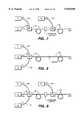
- FIG. 2is a schematic side view of a laser-injected, optical fiber amplifier, as applied to a frequency doubler waveguide, comprising a first embodiment of first basic approach of this invention.
- FIG. 3is a schematic side view of respective portions of a signal injected, two-stage, optical fiber amplifier comprising a second embodiment of the first basic approach of this invention.
- FIG. 4is a cross-section of a double clad, rare-earth doped fiber amplifier that may be employed in conjunction with any of the embodiments of this invention.
- FIGS. 5is a timing diagram of optical power versus time, illustrating the pulsed pumping operation, with pulsed pump duty cycle, relative to the first embodiment shown in FIG. 2.
- FIG. 6relates to a generic schematic representation of a second basic approach of this invention.
- FIG. 7is a schematic illustration of a first embodiment of the second basic approach shown in FIG. 4.
- FIG. 8is a schematic illustration of a second embodiment of the second basic approach shown in FIG. 4.
- FIG. 9is a schematic illustration of a third embodiment of the second basic approach shown in FIG. 4.
- FIG. 10illustrates a two stage double clad amplifier in accordance with another aspect of this invention relating to coupling efficiency of the injection source with the first stage amplifier.
- FIG. 11is an end view of the input face of the first stage amplifier of FIG. 10 illustrating the overlap of the injection source beam of the fiber core.
- FIG. 12is a further embodiment of this invention comprising a first and second stage amplification system utilizing either or both of the first and second basic approaches of this invention.
- FIG. 12Ais a graphical representation of a power versus time or position output for the second stage amplifier array of FIG. 12.
- FIG. 13is a modified form of the first stage amplification shown in FIG. 12 approach providing for double pass amplification.
- FIG. 14is a schematic illustration of first type of multi-wavelength light source for application as a multi-wavelength pumping source for an optical a fiber amplifier system.
- FIG. 15Ais a schematic illustration of a second type of multi-wavelength light source for application as a multi-wavelength pumping source for an optical a fiber amplifier system.
- FIG. 15Bis a graphical illustration of the wavelength band produced by the multi-wavelength light sources of FIG. 15A.
- FIG. 16is a schematic illustration of a third type of multi-wavelength light source for application as a multi-wavelength pumping source for an optical a fiber amplifier system.
- FIG. 17is a schematic illustration of a multiple redundant light source for application as a pumping source for an optical a fiber amplifier system.
- FIG. 1Adiscloses a conventional rare-earth doped, double clad fiber amplifier 10 comprising a single mode, rare-earth doped core and a multi-mode inner cladding. These fiber amplifiers are doped with rare-earth ions, such as Nd 3+ , Yb 3 , Tm 3+ or Pr 3 .
- the fiber amplifieris pumped by a pump source, P s having wavelength ⁇ p , with its input coupled to the fiber multi-mode inner cladding and comprises a high power laser diode or laser array that is operated cw providing a power level, for example, around 100 mW or more.
- An injection signal S 1 of wavelength ⁇ sfrom injection signal source, I s , having a predetermined high repetitive rate or frequency, such as ten's of kHz to several MHz, is provided as input into the core of amplifier 10 which may be a single mode core.
- High peak powers for an amplified pulse signal, S 2with wavelength ⁇ s at the amplifier output, such as, on the order of 100's of watts of pulse peak power to 100's of kW of pulse peak power, or even several MW of pulse peak power, if certain conditions for operation of the fiber amplifier are met.
- Pumping of the rare-earth doped, double clad fiber amplifier 10may be also accomplished with the use of a fiber laser as illustrated in FIG. 1B.
- the pumping source for amplifier 10comprises fiber laser 12 having formed fiber gratings 12A and 12B for optical feedback.
- Fiber laserreceives a pumping signal, ⁇ p , from pumping source, P s , via coupling lens 10L.
- Fiber laser 12may be a double clad fiber with a single doped core fiber, the core being doped, for example, doped with Nd 3+ , Yb 3 , Tm 3+ or Pr 3 , and receives power from laser diode pump source, Ps, through lens system 10L the pump signal S 1 of wavelength ⁇ p which is within the absorption band of the doped fiber core.
- the higher power output from fiber laser 12is provided as input to the inner cladding of rare-earth doped, double clad fiber amplifier 10 by means of being integral with the fiber, i.e., the same fiber, or are of separate fiber bodies with optical coupling provided between the fibers by means a lens similar to coupling lens 10L (not shown).
- an array of pumping sources, 12 s1 , 12 p2 , . . . 12 sncomprising rare-earth doped fiber lasers, may be utilized, as shown in sig. 1C.
- a high level of pump poweris required for injecting into the inner cladding of double clad fiber amplifier 10 via lens system 10L.
- the pump poweris determined by the brightness of the pump source. A low brightness source is focused into a large area and, therefore, relatively few low brightness sources can be coupled into the inner cladding of the amplifier.
- An ideal pump source for the high power double clad amplifier 10is, therefore, one or more double clad fiber amplifiers or lasers with an output wavelength at the absorption band of double clad fiber amplifier 10.
- An example for FIG. 1Cis the pumping of a double clad Er:Yb doped fiber amplifier 10 at 1.06 ⁇ m wavelength with an array of Nd or Yb doped double clad fiber lasers 12 s1 , 12 s2 , . . . 12 sn , providing outputs a around 1.06 ⁇ m wavelength due to reflective gratings 14 G1 , 14 G2 , . . . 14 Gn that maintain their operation at this selected wavelength.
- the gain saturation of the fiber amplifieris determined at high pulse rates, such as those in excess of tens to hundreds of kHz, by the average injection pulse power.
- the average injection power of the input pulsesmust be of sufficient pulse length or duration for efficient pulse amplification to saturate the average output power from the fiber amplifier.
- the pulse lengthmay be, for example, 10 nsec or less up to about 1 msec.
- the gain responseis very slow as compared to recovery shown in FIG. 1D.
- the gain in the fiberis approximately constant and the gain for the input pulses is the same as the average gain.
- the gain recovery present at the time of the signal pulsemay be substantially higher than the average gain in the case of FIG. 1E.
- the maximum peak gainis determined by the onset of substantial levels of scattering noise. However, since the scattering noise has less time to build up, the peak gain will be higher than the average gain.
- a specific implementation of the operation of the fiber amplifier of FIG. 1Acomprises a Nd 3+ doped double clad fiber amplifier pumped with a pump source, P, comprising a P6 fiber coupled, laser diode array having a wavelength, ⁇ p , at 804 nm-808 nm and providing gain at around 1.06 ⁇ m.
- the injection source, I swas a high power tunable laser diode, which is tuned to a wavelength, ⁇ s , of 1.06 ⁇ m.
- the output of the injection source, I swas modulated at a high frequency, via an acousto-optic modulator, and coupled into the single mode core of the double clad fiber amplifier.
- an injected pulse signal, 150 kHz, of rectangular pulse shape with a duty cycle of 6%, 40 mW DC peak power from a laser diodewas amplified to have a DC amplified output power of 29 W peak power, and a pulse energy of 15 ⁇ J.
- the pulse energycan be increased at a lower injection pulse frequency as long as the peak gain between pulses does not exceed the gain levels at which scattering noise depletes the pump power.
- FIG. 2illustrates in more detail, the pumped optical amplifier medium of this first basic approach of the invention.
- a laser injection source 11emits coherent light pulses at a wavelength ⁇ s , which are injected into an optical fiber amplifier 13 to develop high peak powers and pulse energy levels.
- the amplified pulses emitted from fiber amplifier 13may be used for any of a number of possible applications, including nonlinear frequency conversion, laser printing and LIDAR (light detection and ranging).
- LIDARlight detection and ranging
- a second harmonic generator (i.e., frequency doubler) 15 in the form of a nonlinear crystalis illustrated as an application, and receives the amplified pulses from amplifier 13 at wavelength ⁇ s and efficiently produces pulses at a converted wavelength (1/2 ⁇ s ).
- the conversion efficiency in such doubler crystals 15 and other nonlinear devicesis directly related to the instantaneous optical intensity which is coupled into those devices, and thus depends on the peak pulse power levels achievable by fiber amplifier 13.
- Collimating and focusing optics 39couple the light between the several consecutive stages 11, 13 and 15.
- Such optics 39may include any convenient combination of lenses and optical fiber waveguides as is conventional in the art. Alternatively, multi-coupling may be employed between the laser diode fiber and the nonlinear crystal.
- the laser source 11comprises a semiconductor laser diode 21 or a semiconductor MOPA device.
- a laser modulator with an external modulator, a DBR laser or MOPA with DBR oscillatormay comprise source 11 because they exhibit reduced chirp under pulsed conditions and thus emit light of a single (narrow band) stable frequency or wavelength even at high pulse repetition rates, such as in excess of 1 MHz, to peak power levels of at least several 100 mW.
- the laser diodemay employ an unstable resonator geometry with a flared gain region for generating higher output power while preserving single spatial mode emission.
- Such a MOPA type of deviceis preferably constructed with a flared amplifier section coupled to a single mode laser oscillator section and possibly an optional single mode preamplifier section, a saturable absorber, or a modulator element.
- a flared amplifier sectioncoupled to a single mode laser oscillator section and possibly an optional single mode preamplifier section, a saturable absorber, or a modulator element.
- preamplifier sections, a saturable absorbers, and a modulator elementsU.S. Pat. No. 5,392,308, assigned to the assignee herein, and U.S. Pat. No. 5,175,643, assigned to Xerox Corporation, are incorporated herein by reference.
- the fiber amplifier 13comprises a rare-earth doped optical fiber 23 and a high power optical pump source 25.
- the rare-earth dopant for the fiber 23may be any of those conventionally employed in fiber amplifiers and lasers to achieve gain via stimulated emission, including neodymium (Nd 3+ ), ytterbium (Yb 3+ ), erbium (Er 3+ ), thullium (Tm 3+ ), holmium (Ho 3+ ), and a combination of erbium and ytterbium (Er 3+ :Yb 3+ ).
- the wavelength ⁇ s of the input pulses from the laser source 11is selected to match the gain band of the particular active dopant.
- neodymiumthis is most commonly about 1.06 ⁇ m, but also 0.90 ⁇ m to 0.95 ⁇ m; for ytterbium, from 1.03 to 1.14 ⁇ m and also from 1.26 to 1.34 ⁇ m; for erbium or Er:Yb, about 1.54 ⁇ m; for thullium, about 1.7 ⁇ m or 2.0 ⁇ m; and for holmium, about 2.1 ⁇ m.
- the pump wavelength ⁇ pis likewise selected to match the absorption wavelength band for the particular dopant employed in the fiber amplifier. There is usually some variability in these wavelength bands depending on the glass fiber core material selected to serve as the host for the dopant. Usually, a silica glass is employed.
- the fiber 23is preferably a double clad fiber with a central core 29 of a first refractive index that is doped with the rare-earth active ions, a first inner cladding 31 of a second, lower refractive index surrounding the core 29 and a second outer cladding 33 of a third, further lower, refractive index surrounding inner cladding 31.
- the corefunctions as a waveguide and amplifying medium for the input pulses, while the inner cladding functions as a waveguide for the pump light.
- Core 40preferably has a diameter of less than about 10 ⁇ m and supports propagation of only a single spatial mode of the light.
- Inner cladding 42is typically a multimode waveguide and has a size and shape selected to match that of the pump light received from pump source 25 for maximum coupling efficiency.
- a rectangular shape, as shown,is typical, although an elliptical or any other shape might also be used.
- Outer cladding 44serves to confine the pump light to core and inner cladding regions 40 and 42.
- fiber end surfaces 30 and 32may be polished at a slight 12° to 15° angle from the fiber normal to minimize reflective feedback of the light propagating in the fiber.
- the fiber endsmay also be antireflection coated.
- Pump source 25is preferably a high power, high brightness, fiber coupled, laser diode array.
- the laser diode arrayis fiber coupled to end surface 30 and consists of multiple semiconductor laser diodes to provide for redundancy to improve the reliability of the source and the system.
- Pump source 25may also be a MOPA or a doped single clad fiber pump source.
- the provided output powershould be at least several 100 mW, and preferably 10 W-20 W or higher, average output power in a continuous, quasi-continuous or pulsed mode.
- GaAlAs monolithic linear laser arrays emitting pump light in the 798-810 nm rangeinclude the 3400 series (continuous) and 3200 series (quasi-cw) from SDL, Inc., of San Jose, Calif.
- the SDL-3450-P5provides 10 W of continuous output from a 400 ⁇ m diameter, 0.4 NA fiber bundle.
- the SDL-3251 barsprovide 100 W peak quasi-cw output from a 10 mm by 1 ⁇ m emitting aperture (10 by 30 FWHM beam divergence) for a 400 ⁇ sec maximum pulse width (40 mJ/pulse) and a duty factor of up to 40% (4 W average power).
- InGaAs monolithic linear laser arrays emitting pump light in the 960-980 nm rangeinclude the SDL-6480-P5 fiber-coupled laser with 10 W cw output like the SDL-3450-P5 laser mentioned above and the SDL-6231 laser bars providing 60 W peak quasi-cw output from a 10 mm by 1 ⁇ m emitting aperture (10 by 40 FWHM beam divergence) for a 400 ⁇ sec maximum pulse width (24 mJ/pulse) and a duty factor of 2 to 3% (1.2 to 1.8 W average power). Stacked arrays with even greater quasi-cw outputs are also available. InGaAsP/InP lasers can produce pump light for longer wavelength thullium and holmium fiber amplifiers.
- the pump light from laser pump source 25is coupled via the dichroic beamsplitter 27 and a focusing lens 39 into inner cladding 31 of optical fiber 23 and is absorbed by dopant ions in fiber core 29 as it propagates down the length of the fiber to create gain for the light pulses from injection signal source 11.
- Pulsed operation of the laser diode or MOPA device 21 of injection signal source 11may be achieved by pulsing the electric current I(t) injected into device 21.
- the pulsed injection current I(t)is supplied only to a portion of the device, such as to a single mode waveguide section, while other portions, including any flared gain section, are pumped independently with DC current.
- pulsed currentmay be supplied to a MOPA device's oscillator or preamplifier section, while DC current, not necessarily uniformly distributed, may be injected into the MOPA's flared amplifier section.
- the result of this pulsed current injection I(t)is a pulsed optical output from the device 21 whose pulse characteristics correspond to the current pulses. It is thus possible to tailor the optical pulse duration and shape by tailoring the injection current pulses.
- Pulse shapingis important for certain applications and, for example, optical parametric oscillators (OPO) or optical parametric amplifiers, where the conversion efficiency strongly depends on input power. In these types of situations, a pulse with a slow buildup or rise time will result in low efficiency.
- pulsed operationmay be achieved by using Q-switching or mode locking techniques to produce subnanosecond (or even subpicosecond) pulses.
- the laser source 11may incorporate an active electro-optic or magneto-optic modulated loss element in the laser cavity, or a passive cavity loss element, such as a saturable absorber in the laser diode structure, to induce Q-switching.
- the injection currentmay be modulated at a rate timed to match the round trip travel time of the cavity to induce mode locking.
- a combination of mode locked operation and a Q-switch element to the repetition rate of the mode locked pulsesmay be used.
- the characteristics of the optical pulses emitted from the laser source 11typically include a sub kHz-100 MHz repetition rate for a 1 nsec to several msec time period between successive pulses, a duty cycle of 10% or less for pulse lengths of 10 nsec or less, peak power levels of from 100 mW to 1 W or more, pulse energies of about 1 nJ to 0.1 ⁇ J per pulse, and average power on the order of 1 mW. It is important for minimizing scattering noise to inject sufficient optical power from the laser source 11 into the fiber amplifier 13 to saturate the gain of the fiber medium. At high modulation rates, the gain saturation for a given fiber amplifier 13 is largely determined by the average power of the laser source.
- the received input power to the fiber amplifier 13is 1 mW or higher to achieve gain saturation.
- operation with over 50 dB gainis achievable so that even lower injection source powers are all that is necessary to provide sufficient output power for desired applications.
- the repetition rate of the pump power from pump source 25is chosen to allow time for adequate gain recovery in the fiber amplifier 13 between pulses.
- the duty cyclerelates to the peak power of the amplified pulses from injection signal source 11. A low duty cycle concentrates the pulse energy into a shorter duration for higher peak power levels.
- the amplified output pulses of wavelength ⁇ s emitted from output surface 32 of fiber 23may be coupled into an optically nonlinear frequency conversion element, such as a frequency doubler 15.
- the frequency doubler 15may comprise a bulk KNbO 3 crystal 35 with a QPM waveguide 37.
- waveguide 37may be periodically poled with alternating ferroelectric polarization domains (+ and -) to maintain phase matching of the amplifier output of wavelength ⁇ s injected into the waveguide with the converted light of wavelength (1/2 ⁇ s ) generated in the waveguide by the nonlinear second harmonic generation process.
- Light pulses received from a neodymium fiber amplifier with wavelength in a range from 900 nm to 950 nmare converted to pulsed blue light with a wavelength ranging from 450 nm to 475 nm.
- green light pulses of from 515 nm to 570 nm wavelengthcan be generated from the 1030 nm to 1140 nm pulsed output from a praseodymium fiber amplifier or the 1060 nm pulsed output of a neodymium fiber amplifier.
- the efficiency of the second harmonic generation processis related to the optical power density of the light pulses coupled into the nonlinear waveguide.
- the high peak power levels from a pulsed fiber amplifierconvert much more efficiently than continuous, but lower power outputs.
- the high peak power levels achievable through the utility of this inventione.g., 1 to 10 kW or higher, permit higher efficient doubling in bulk crystals, which is an important attribute of this invention relative to applications requiring high power inputs for greater efficiency in operation.
- Conversion efficiencyalso depends upon the wavelength and polarization stability of the amplified light pulses. A single narrow wavelength band is preferred, since linewidth broadening and chirp reduce doubling efficiency.
- injection signal source 11may be a DBR laser or other stable wavelength sources to stabilize the amplification wavelength including a laser diode source stabilized by external grating feedback or a laser diode with external modulation.
- single polarization from fiber amplifier 13is also preferred. This may be achieved with a combination of a stable input polarization from injection signal source 11, a polarization preserving fiber 23, or a fiber polarization controller near output end 32 of optical fiber 23, such as a mechanism for stressing the fiber, with a feedback control loop sensing the output polarization.
- a polarizing filtermight also be place between fiber output at face 32 and the input to waveguide 37.
- resonant frequency conversion processessuch as optical parametric oscillation (OPO)
- OPOoptical parametric oscillation
- LIDAR systemsmake use of multi-watt peak power pulses in excess of 1 ⁇ J/pulse energies in the near to mid infrared range.
- the pulses directly from the fiber or generated by OPO-converted fiber amplifier outputscan be used in such LIDAR systems.
- FIG. 3which is divided into FIGS. 3A and 3B, is another embodiment in accordance with the basic first approach.
- a cascaded or multi-stage fiber amplifiercomprising a first amplifier source 51 having a injection signal source 51a to be amplified, which may be a laser diode, and a first pumped fiber amplifier 51b optically coupled to a second pumped fiber amplifier 53.
- Injection signal source 51ais similar to source 11 in FIG. 3A so that laser diode 61 may be the same as laser diode 21 in FIG. 2.
- Laser 61may be operated in a pulsed mode via a pulsed current injection signal I(t) as in the case of laser 21.
- First fiber amplifier 51bamplifies the injection signal pulses to kilowatt peak power levels for injection into second fiber amplifier 53 which provides further amplification of the amplified signal to megawatt peak power levels.
- a low power laser diodemay be employed for injection signal source 51a providing pulses of about 100 mW peak power or less. The lower power helps to maintain single frequency operation without chirping, which results in single frequency, amplified outputs.
- First fiber amplifier 51bamplifies the signal pulses to a range of about 1 W to 10 W peak power levels.
- First fiber amplifier 51balso makes possible the use of input pulses of more moderate repetition rates (under 1 MHz) and larger duty cycles (about 1-10%) while still providing the 1 W to 10 W peak power pulses to second fiber amplifier 53 required for amplification to 10 kW to 100 kW peak levels.
- pulse durations of 10 nsec or lessare usually preferred, there may be some applications where longer pulses of up to 1 ⁇ sec duration are desired for greater pulse energies.
- the pulsesmay be generated either by direct current injection I(t), as before, or by an external modulator.
- First fiber amplifier 51bcomprises a rare-earth doped fiber 63 and a laser diode pump source 65.
- Fiber 63may be a double clad fiber, like fibers 23 and 73, or can be a conventional single-clad fiber, as shown here.
- Light pulses at the amplification wavelengths ⁇ s from laser diode 61 and pump light at pump wavelength ⁇ p from pump source 65are combined, via a dichroic beamsplitter 67 or other beam combining optics, and injected into core 69 of fiber 63.
- Input and output end surfaces or faces 70 and 72may be polished at an angle, antireflection coated or both to minimize reflective feedback in fiber 63.
- Second fiber amplifier 53 in FIG. 3Bis similar to amplifier 13 of FIG. 2, having a double-clad fiber 73 and a high power laser diode pump source 75.
- a dichroic beamsplitter 77combines the pump light of wavelength ⁇ p with the light pulses of wavelength ⁇ s to be amplified received from source 51.
- the light pulses to be amplifiedare coupled into a rare-earth doped core 79 of fiber 73, while the pump light is coupled into the inner cladding 81 surrounding core 79.
- a second or outer cladding 83confines the pump light to core and inner cladding regions 79 and 81.
- the fiber input and output surfaces or faces 80 and 82may be polished at an angle, anti-reflection coated, or both to minimize reflective feedback within optical fiber 73.
- the rare-earth dopant for first fiber amplifier 51bneed not be same as the dopant in second fiber amplifier 53, provided that the dopants employed in both first and second fiber amplifiers 51 and 53 provide gain at the same wavelength ⁇ s from injection signal source 61.
- the dopants, neodymium and ytterbiumhave overlapping gain spectra at 1.06 ⁇ m.
- the pump wavelengths ⁇ p from pump sources 65 and 75need not be identical, provided both wavelengths fall within the corresponding pump absorption wavelength band or bands for first and second amplifiers 51b and 53.
- first fiber amplifier 51bmay be pumped at about 970 nm while a neodymium doped, second fiber amplifier 53 may be pumped at about 808 nm.
- second fiber amplifier 53may be pumped at about 808 nm.
- the average pump power levels for pump sources 65 and 75will, in general, not be identical. Rather, pump source 65 for first fiber amplifier 51b should have a lower average power than pump source 75 for second fiber amplifier 53 because first fiber amplifier stage 51b need only be pumped to provide a much lower average output power than second fiber amplifier stage 53. This will allow first fiber amplifier 51b to be saturated by the light pulses from source 51a minimizing the potential influence of scattering noise.
- the pulsesare amplified to higher average and peak power levels in first fiber amplifier 51b, and the amplified pulses are injected into second fiber amplifier 53 for further amplification.
- the higher power levels of the preamplified pulsesallow second amplifier 53 to be pumped by pump source 75 to higher levels while still maintaining saturation minimizing the potential influence of scattering noise.
- Both first and second pump sources 65 and 75may be linear laser diode arrays or flared amplifier, semiconductor MOPA devices.
- Second pump 75 for second fiber amplifier 53may, alternatively, be a stacked laser array. All of the elements in the cascaded fiber amplifier system of FIG. 3 are optically coupled to one another by collimating and focusing optics 89, typically in the form of lenses, but may also be coupled via optical fibers.
- scattering noisecan also be minimized with a proper choice of pulse repetition rate for the input pulses or with a pumping technique in a cascaded amplifier configuration by means of gain switching.
- the rare-earth dopant in the fiber core of these amplifierstypically have fluorescence time constants in a range from about 400 ⁇ sec to 700 ⁇ sec, which is directly associated with the onset of scattering noise. Accordingly, if the pump power were held substantially constant at about 1 W to 10 W cw, then the input pulse repetition rate of the injection signal I(t) must be selected to be sufficiently high so that the interpulse duration is not greater than the fluorescence time constant.
- FIG. 5shows a timing diagram for one duty cycle of the injected signal input (A) and pump pulse (B) relative to the fiber amplifier of FIG. 3, providing amplified output pulse (C), when the amplifier is operated with a pulsed pump source. Instead of being continuous, the pump source is pulsed so as not to be continuous during the complete duty cycle.
- Pump pulses 41have a duration of from 10 ⁇ sec to 500 ⁇ sec, which is sufficiently short to avoid the onset of scattering noise.
- the 0.1 mJ to 5.0 mJ of pump energy supplied by a pump pulse with 10 W to 20 W peak poweris stored in the excited states of the dopant ions until released by stimulated emission from injection of an input pulse 43 into the fiber amplifier shortly before the end of the pump pulse at time to.
- Input pulse 43typically has a peak power of about 1 W and a pulse duration of about 10 ⁇ sec, although shorter pulses with higher peak power levels are also possible.
- the stored energy in the fiber amplifieris converted into an output pulse 45 of approximately the same pulse duration as input pulse 43. In this manner, 10 nsec output pulses 45 having about 10 kW to 100 kW peak power are achieved without the buildup of scattering noise.
- FIG. 6illustrating a second basic approach of this invention.
- a buildup of scattering noisecan occur from saturating the amplifier, particularly in cases where large gains are required. Such saturation can occur, for example, with gains at 30 dB or above.
- the backtraveling noise from the second amplifieris coupled back into the first amplifier, where it is amplified, saturating the first amplifier.
- the noisemay be amplified to such a great extent that amplification of the desired signal cannot be effectively achieved. Desthieux et al.
- a first pump signal 92is provided as input to a first amplifying medium 94, along with the injected signal 90 to be amplified, having a first duty cycle 96.
- the amplified injected signal 90' from the first amplifier medium 94is supplied as input to a second amplifying medium 102 along with a second pump signal 100 having a second duty cycle 104.
- a characteristic of the first and second duty cycles 94 and 104is that the pulse length or duration 98 of the first duty cycle 96 is shorter than the pulse length or duration 106 of the second duty cycle 104.
- the backtraveling scattering noise from the second amplifying medium 102is reduced to a very short time period for any possible amplification in the first amplifying medium 94 so that saturation in the first amplifier medium 94 is not substantially consumed through amplification of such scattering noise.
- much higher levels of output powers and energiescan be achieved at the output of second amplifying medium 102 than previously achieved, including that achievable by B. Desthieux et al., supra.
- the shorter pulse length or duration 98is preferably in the first duty cycle 96 rather than in the second duty cycle 104.
- the pulse durations 98 and 106may also be of the same length.
- the inventive conceptis still operative when the pulse length or duration 106 in second duty cycle 104 is shorter than pulse length or duration 98 in the second duty cycle 96 to reduce scattering noise, in particular, with respect to forward scattering noise. The important point in conjunction with each of these three pulse duration relationships between the first and second pump pulses is to ensure that the injection pulse receives the available gain of the amplifying medium.
- the pulse relationshipmay be a constant time relationship or vary with time. In either case, the synchronization needs to be maintained so that the injection pulses 90 and 90' occur in proximity to the terminal end of respective pump pulses 92 and 100 thereby assuring optimum available gain buildup in medium 94 or 102. therefore, the injection pulses can be synchronized to be overlapped or immediately adjacent to on either positional side of the terminal end of the pump pulse.
- one pump outputmay be cw and the other pump output may be pulsed.
- pump 92may be pulsed while pump 100 may be operated cw.
- FIG. 7illustrates a first embodiment for accomplishing the amplifier operational scheme of FIG. 6.
- First amplifying medium 94comprises an optical fiber amplifier A 1 , e.g., an erbium doped fiber amplifier (EDFA).
- Injection signal, ⁇ sfrom injection signal source I s via optical coupling 90, together with first pump signal, ⁇ p1 , from pump source P 1 via optical coupling 92 and beam splitter BS 1 , are provided as input to first optical fiber amplifier A 1 .
- EDFAerbium doped fiber amplifier
- the output from amplifier A 1is coupled, via standard coupling optics, to an optical input to second amplifying medium 102 comprising optical fiber amplifier A 2 , e.g., an erbium doped fiber amplifier (EDFA), via coupling optics (conventional collimating and focusing lens system), together with second pump signal, ⁇ p2 , from pump source P 2 via optical coupling 100 and beam splitter BS 2 .
- optical fiber amplifier A 2e.g., an erbium doped fiber amplifier (EDFA)
- EDFAerbium doped fiber amplifier
- Any scattering noise, including backtraveling noise from amplifier A 2 into amplifier A 1is not available for saturating amplifier A 1 during the duty cycle of the first pump signal 92 except during the relatively short pulse duration 98 when the latter pump signal is active during its is cycle, which is a comparatively short period of time relative to its total cycle time 96.
- the amplification of scattering noiseis suppressed by gain switched pumping of the first stage amplifying medium, A 1 , with short, several msec long, high power pump pulses having a duration much shorter, such as between 10 ⁇ sec and 500 ⁇ sec, than the fluorescence time constant of the amplifying medium, which constant is generally in the range of about 400 msec to 700 msec (for Nd 3+ it is about 400 ⁇ sec) and is associated with the buildup of the scattering noise.
- the second stage amplifying medium, A 2is pumped with a longer pulse length, such as around 500 msec or higher, in order to deliver the required energy to the second stage amplifier to provide very high energy output pulses of 10 mJ or more.
- the amplifiermay be a multimode core, double clad fiber or a multimode, single clad fiber to support even higher peak powers. Because the shorter pump pulse lengths are employed in the first stage amplifying medium, the scattering noise in the first amplifier is effectively gated out, while being synchronous with the input of the cw or pulse injection signal to be amplified without the necessity of any active modulator between the two amplifying media 94 and 102. By reducing the pump pulse duration in the first amplifier, the possible buildup time for the scattering noise is significantly reduced and the SNR of the pulse output is improved. The necessity or requirement of an isolator or other noise suppressor between amplifiers A 1 and A 2 is substantially eliminated.
- the first stage amplifier, A 1may be pumped with a 100 W pulse having a 4 ⁇ sec pulse length, which corresponds to a pump pulse energy of 0.4 mJ.
- the signal pulse to the first stage amplifiermay be a 10 nsec pulse having a peak power of 1 W. This is sufficient for 0.1 mJ pulse energy from the first stage amplifier achieving an amplified peak power output from this stage of about 10 kW.
- the second stage amplifier, A 2may be pumped with a 100 W pulse having a 500 ⁇ sec pulse length, which corresponds to a pump pulse energy of 50 mJ. This is sufficient for tens of mJ pulse energy from the second stage amplifier achieving an amplified peak power output from this stage of about 1 MW.
- FIG. 8illustrates a second embodiment for accomplishing the amplifier operational scheme of FIG. 6.
- the second embodimenthas an advantage over the first embodiment in being more compact and requiring less components, in particular, eliminating the need for the coupling optics, such as shown in FIG. 7 between the first and second amplifying media, A 1 , A 2 . Rather, the two fiber amplifiers A 1 and A 2 may be merely spiced together.
- First amplifier medium 94comprises an optical fiber amplifier A 1 , e.g., an ytterbium (Yb) doped, double clad fiber amplifier (YDFA).
- Ybytterbium
- YDFAdouble clad fiber amplifier
- Injection signal, ⁇ sfrom injection signal source I s , together with both first pump signal, ⁇ p1 , from pump source P 1 and second pump signal, ⁇ p2 , from pump source P 2 , via optical couplings 90, 92, 100 and beam splitter, BS, are all provided as input to first amplifier medium 94 which comprises an optical fiber amplifier A 1 .
- Second amplifier medium 102comprises an optical fiber ampliier A 2 , doped with a different dopant from that of amplifier A, e.g., an neodymum (Nd) doped, double clad fiber amplifier (NDFA).
- Ndneodymum
- NDFAdouble clad fiber amplifier
- the wavelength of the second pump signal, ⁇ p2is chosen such that it is transparent to the absorption spectra of amplifier A 1 .
- second pump signal, ⁇ p2passes through amplifier A 1 , without any affect but, upon reaching second amplifier A 2 , is effective to be absorbed and provide gain to the amplified injected signal 90' (FIG., 6) as the latter traverses through the second amplifier A 2 .
- any scattering noiseincluding backtraveling noise from amplifier A 2 into amplifier A 1 , is not available for saturating amplifier A 1 during the duty cycle of the first pump signal, ⁇ p1 , except during the time of the relatively short duration 98 when the latter pump signal is active, which time duration is a comparatively short period of time relative to total cycle time 96. Moreover, a portion of the backtraveling noise from amplifier A 2 into amplifier A 1 is likely not to even be within the absorption spectra of amplifier A 1 .
- the 920 nm pump lightis provided with a duty cycle that is less than 5% with pulses of short duration or pulse length in order to suppress the buildup of scattering noise.
- This 920 nm pump beamis absorbed in YDFA, A 1 .
- the 808 nm pump lightis provided with a duty cycle that is greater than 20% with pulses of longer duration or pulse length, and travels through first YDFA, A 1 , without absorption, i.e., is transparent to any absorption properties, but is absorbed in second NDFA, A 2 .
- the 808 nm pump lightis operated at a longer pulse length so as to provide high pulse energy.
- the pulse duration for the 920 nm pump beamis comparative very much shorter in time
- the backtraveling scattering noise from second amplifying medium A 2is reduced to a very short time period for any possible amplification in first amplifying medium A 1 so that saturation in the first amplifying medium is not consumed through amplification of the noise.
- much higher levels of output pulse powers and energiescan be achieved at the output of second amplifying medium A 2 by using pulse lengths comparatively much longer in duration compared to that for the first amplifying medium A,.
- the coupling optics between amplifiers A1 and A2can be eliminated and the amplifiers can be spliced together or actually be a single fiber with two different sections with different rare-earth doping, which is discussed in further detail later relative to FIG. 7.
- two separate pump sources, P 1 ) P 2are shown.
- these pump sourcescan be integrated into a single pump source comprising a single laser diode bar wherein a first portion of the bar comprises a plurality of laser stripes operating, as fabricated or as tuned, at the first pumping wavelength, ⁇ p1 , such as 920 nm, and a second portion of the bar comprises a plurality of laser stripes operating, as fabricated or tuned, at the second pumping wavelength, ⁇ p2 , such as 808 nm.
- the respective laser strip outputsare directly coupled to respective input ends of optical fibers which are bundled into a composite group with their bundled output focused into the inner cladding of the first amplifying medium A 1 so that light of both wavelengths ⁇ p1 , ⁇ p2 are optically coupled in the inner cladding of the fiber.
- the configurationis the same as that shown in FIG. 7, except that two separate or independent injection signal sources, I s1 and I s2 , to be amplified and are provided as input to the first amplifying medium A 1 for signal amplification.
- Signal wavelengths, ⁇ s1 and ⁇ s2are both within the gain bandwidth of amplifiers A 1 and A 2 .
- the shorter pump pulse lengthsare employed in the first stage amplifying medium so that the scattering noise in the first amplifier is effectively gated out while being synchronous with the input of the cw or pulse injection signal to be amplified, without the necessity of any active modulator between the two amplifying media.
- the cascaded amplifying mediacan be within a single fiber.
- the length of the single fiberis optimized so as to absorb most of the pump light relative to approximately half of the fiber length.
- the shorter pump light pulseswould be applied to the front end of the amplifying medium along with the injection source light, and the longer pump light pulses would be applied to the back end of the amplifying medium.
- the length of the single fiberis optimized so that a smaller portion of the fiber is doped with a first rare-earth ion species and a second larger portion with a second rare-earth ion species.
- the shorter pump light pulseswould be applied to the front end of the amplifying medium along with the injection source light, and the longer pump light pulses would be applied either through the front or to the back end of the dual-doped amplifying medium.
- medium examples shown for the embodiments for FIGS. 7-9are optical fiber amplifiers, they could be other solid state media, such as solid state rods or doped optical waveguides.
- the need for efficient coupling to the first amplifying stagemay not be a requirement or a necessity due to the obtaining of sufficiently high output power from the multistage fiber amplifiers.
- alignment of the injection signal and pump source outputs on the fiber end input of the first amplifying tageis not critical so that alignment tolerances of these optical components are ased and optical feedback into the sources themselves is reduced.
- FIGS. 10 and 11aid in the explanation of this coupling approach.
- FIG. 10discloses two optically coupled double clad fiber amplifiers A 1 and A 2 having rare-earth doped inner claddings with laser diode source, I s , having a wavelength, ⁇ s1 , that matches the gain bandwidth of both rare-earth doped fiber amplifiers 94 and 102.
- the optimal injection wavelength, ⁇ s1is around 1100 nm.
- Respective pump sources P 1 and P 2provide pumping wavelengths ⁇ p1 and ⁇ p2 at the absorption peak, via beam splitters B s1 and B s2 , to amplifiers 94 and 102.
- an optical isolator 104may be inserted between amplifiers A 1 and A 2 .
- the configuration of FIG. 10is substantially the same as the configuration of the invention shown in FIG. 3A, 3B.
- the light beam from a substantially single spatial mode laser diode source, I sis imaged, via a focusing lens, for example, onto the input face of the core of first stage amplifier 94 for signal amplification along the length of its fiber 110.
- the input coupling into the double clad fiber of the first stageis shown in FIG. 11 wherein fiber 110 has a core 112 and inner cladding 114 and outer cladding 116.
- the injection source light beam, ⁇ ssubstantially overlaps the diametrical size of core 112 so that there is low coupling efficiency of the total power of the pump source into core 112.
- the input of the pump source beam, ⁇ p1is a much broader image but is not filling or complete overlapping the diametrical extent of inner cladding 114.
- a typical single mode diode sourcewould be capable of providing an output power of over 100 mW.
- the gain of the two stage amplifiers A 1 and A 2is capable of delivering high power outputs more than adequate for many applications, much less power levels are needed for signal injection into the fiber core for amplifier A 1 for amplification. Therefore, the coupling efficiency of the light from source, I s , into the amplifier core may be only of a small amount, e.g., less than a mW of power, since the power out of the two stage amplifier will be still sufficient for desired applications.
- the low coupling efficiencyreduces both the necessity of exacting alignment tolerances between the laser source output and the input face of the amplifier fiber and the optical feedback from the fiber amplifier back into the laser diode source.
- an optical isolatormay be inserted in the optical path between laser diode source, I s , and fiber amplifier A 1 to further reduce optical feedback from amplifier A 1 .
- the optical isolatormay be a neutral density filter if the optical losses associated with such devices can be tolerated for the particular application of the dual amplifier system.
- First amplifier A 1may be designated as a pre-amplifier which amplifies the injection source, I s , for a sub mW level, due to low coupling efficiency as explained above, up to power output levels of hundreds of mW from this first stage 94 with a typical gain of about 30 dB.
- the first amplifier A 1may be pumped via source, P 1 , with a single broad area laser diode with an output power in the range of 0.5 W to 2 W. The employment of a higher pump power will result in a higher gain and an improved noise figure.
- the first fiber amplifier A 1may be a single clad fiber pumped with a single mode laser gain matched to the core of the amplifier fiber. The single mode fiber will have a higher efficiency and improved noise figure.
- the output power from the first fiber amplifier stagewill be more limited because of the lower power provided by a spatially coherent pump laser diode as compared to a broad area pump laser diode employed for pumping a double clad fiber configuration, as shown in FIG. 10, via the inner claddings.
- Second stage fiber amplifier 102operates as a power amplifier to amplify the injection signal to a high power level.
- the high injection power injected into amplifier 102permits saturation of the output power at relatively low gains in the range of about 10 dB to 20 dB.
- optical isolator between first and second stage amplifiers 94 and 102prevents any buildup of amplified scattering noise, in particular backtraveling scattering noise comprising Rayleigh scattering and backward ASE.
- the pump powermay be integrated over time, extracting amplified injection signal power in short pulses with high energy.
- the pulse repetition rateis faster than the florescence lifetime of the rare-earth dopant, typically several 100 ⁇ sec. to 1 msec., then, the average injection signal required to suppress scattering noise is approximately equal to the cw injection signal power.
- the required injection source peak powermust be higher than in the case of cw injection power operation by the same factor as the duty cycle.
- the required average injection power levelis much less than 1 mW, it is possible in this pulse mode operation to couple sufficient peak pulse power into the input face of fiber amplifier A 1 by imaging the output from the source on the fiber input face to achieve approximate coupling of a portion of the injection source output beam, as previously illustrated and explained in connection with FIG. 11.
- pulse mode operationwill require more careful matching of the light from the injection signal source, I s , into this first stage amplifier.
- FIG. 12discloses a utility in the combination of the first and second basic approaches relative to a first and second stage amplification system or architecture for pulsed operation providing high output power from an array of double clad fiber amplifiers.
- High pulsed output powerscan be achieved from a double clad fiber array configuration using a pulsed lower power laser diode source as an input oscillator.
- the output power from multi-stage amplifierscan be limited in output power verlapping gain spectra at 1.06 ⁇ m.
- the pump wavelengths Firstthe peak output power of the multi-stage amplifier may exceed the damage level of the fiber employed for the amplifiers.
- the peak output power of the multi-stage amplifiermay lead to nonlinear interaction in the fiber resulting in scattering loss reducing the resultant power output level.
- the pulse energyis limited by the pump coupled into a single double clad fiber and, in the case of several series coupled stages, the total output power will be limited by coupling losses between amplifier stages. In FIG.
- Injection source, I s , and pump sources, P 1 and P 2 , in the first stagemay be pulsed laser diode sources or other pulsed laser sources.
- the injection source signal, ⁇ sis amplified by a series of either single clad fiber amplifiers or double clad fiber amplifiers or a combination of single clad and double clad amplifiers A 1 , A 2 , . . . A n , to provide sufficient average power and peak power to saturate the second stage of the amplifier configuration.
- Two doped fiber amplifiers 120 and 124are shown in FIG. 12 in this illustration and are respectively supplied with pumping power from laser sources P 1 and P 2 .
- Amplifiers A 1 and A 2are operated in a manner explained in connection with either the first or second basic approaches explained, respectively, relative to FIGS. 1-5 and FIGS. 6-11.
- the output 125 from the first stageis split into a plurality of single mode fibers employing a beam distributing means 126, such as three-way beam splitter 126A and associated mirrors 126B, to distribute the power substantially in a uniform manner over the entire fiber amplifier array 130.
- a beam distributing means 126such as three-way beam splitter 126A and associated mirrors 126B
- inputs to amplifiers 130A, 130B, 130C, . . . 130nare fairly the same as well as being sufficient to saturate the amplifier.
- the outputcan be combined, in the manner as previously indicated, or can be coupled to another array of double clad fiber amplifiers through the employment of a microlens array to combine the light from array 130 in order to optimize output brightness.
- Double clad fiber amplifier array 130are typically operated deep into the saturation regime to optimize the efficiency of these amplifiers.
- the output power from each of the double clad fiber amplifiers 130A, 130B, 130C, . . . 130nwill not be sensitive to the input power delivered from the first stage, provided that the input power from the first stage is sufficient to saturate the gain of the amplifier array.
- the pump pulsing scheme of the second basic approachmay be employed relative to the first and second stages of FIG. 12 wherein, in the first stage, pump sources P 1 and P 2 provide pulse outputs of pulse duration 92 relative to duty cycle 96 and pump sources P 3 , P 4 , P 5 provide pulse outputs of pulse duration 100 relative to duty cycle 104.
- the lengths of the fibers comprising the amplifier array 130should be all substantially of equal length to insure that all of the pulses emitted from the double clad fiber amplifiers 130A, 130B, 130C, . . . 130n overlap or are uniformly synchronized in time.
- different lengths of these fibersmay be employed to achieve different delays in time of the pulse output from array 130.
- all pulsed amplified outputs from the amplifiers of array 130are synchronized, they will be additive either in time or in position so that the single pulse output may be a combined, large output power pulse.
- output pulse shapingcan be accomplished by arranging the output pulses from the respective amplifiers to be overlapped, time synchronized or position synchronized in a manner to produce, for example, a step increasing and step decreasing pulse shape such, as illustrated in FIG. 12A.
- FIG. 12Arepresents combined pulse output of an amplifier array 130 comprising 10 amplifiers 130n time sequenced to produce the shaped series of pulses 150 where the fiber lengths of selected amplifiers are selected to be additive in time or position, such as is the case for amplifiers A 3 , A 7 , A 9 and A 10 in FIG. 12A.
- any combination of time or position selection of the pulsed output of respective amplifiers A 1 -A 10can be realized.
- the first stage of FIG. 13comprises a single clad or double clad amplifier 120 optically coupled to receive an injection signal, ⁇ s , from source, I s ) and pump signal, ⁇ p , from source, P s , which are combined via beam splitter 123 for input to amplifier 120 via isolator 132 and a second beam splitter 133.
- the amplified output 135 of amplifier 120is reflected back into fiber amplifier 120 by reflective element 134 so that amplifier 120 functions as a double-pass amplifier where the returning amplified light is reflected at beam splitter 133 for output 125 to the second stage comprising amplifier array 130 in FIG. 12.
- Amplifier 120may be operated in a manner explained in connection with the first basic approach previously explained relative to FIGS. 1-5.
- Optical amplifying mediaconsisting of a single core fiber or a double clad fiber may be utilized wherein, respectively, the core or inner cladding is doped with a rare-earth ionic species providing a predetermined gain spectrum for the fiber to which the pumping wavelength must be matched. Since the gain spectrum of the laser diode pump sources changes as the temperature changes, a given pumping source coupled to the fiber amplifier may no longer match the gain spectrum of the fiber if the laser pump source begins operating at a different operating temperature.
- One approach for correction of this situationis to provide a pump source comprising a plurality of different spatially separate wavelengths which are all coupled into the fiber amplifier.
- the multi-wavelength laser diode pump sourcechanges wavelength with temperature, such as in a range within about -15° C. to about 125° C.
- at least one of the output wavelengthswill overlap the gain spectrum of the fiber amplifier sufficiently to continually provide high input power for pumping of the fiber.
- Such a monolithic multi-source laser diode device 140is shown in FIG. 14 having a plurality of laser stripes wherein single stripes of or groups of laser stripes may be designed to operate at different wavelengths ⁇ 1 , ⁇ 2 , ⁇ 3 and ⁇ 4 .
- the output of device 140is then imaged through conventional optics 142 via beam splitter 144 into rare-earth doped, optical fiber amplifier 146.
- a portion of the output from amplifier 146is received by detector 150 via beam splitter 148 to provide feedback to laser diode device 140 via current controller 152 which is sensitive to at least a portion of the optical output from fiber amplifier 146 to vary, e.g. increase, the current excitation level of laser diode 140 to simultaneously provide optimized pump power within the gain spectrum of fiber amplifier 146.
- pumping source 140 in this embodimentmay be comprised of a series of separate laser diodes operating or tunable to different wavelengths as shown in FIG. 15A.
- Laser diode sources 160, 161 and 162may be individual multimode laser diodes or diode laser bars producing, respectively, the wavelength spectrums or bands 163, 164 and 165, as illustrated in FIG. 15B.
- Wavelength spectrumsmay be extended in wavelength band relative to each other or slightly overlapped in wavelength. The extent of the wavelength bandwidth across spectrums or bands 163, 164 and 165 may be in the range of 20 nm to 30 nm.
- Sources 160-162have their outputs coupled via lens systems 166 into respective optical fibers 167, 168 and 169 which at their output end, are tightly bundled together for focused coupling of their light beams by lens 170 into doped inner cladding layer 172 of double clad fiber amplifier 171.
- the injection signalis provided to core 173 of fiber 171 for amplification.
- a portion of the output from fiber amplifier 171may be diverted to detector 150 and current controller 152 to vary the current excitation level of the individual laser diode sources 160-162 to simultaneously provide optimized pump power within the gain spectrum of fiber amplifier 171.
- the multi-wavelength pumping sourceis coupled either by a dichroic beam combiner and focusing lens system to the input of fiber amplifier 146, as shown in FIG. 14, or the individual outputs of sources are butt coupled to respective optical fibers and bundled for optical coupling, such as by means of a focusing lens system, as shown in the case of fiber amplifier 171 in FIG. 15A.
- FIG. 16to an injection source 180 of narrow wavelength emission is shown with pumping source 181 where the beams are combined via polarizing beam splitter or dichroic mirror 182 for focused input via lens system 183 into the single mode, fiber core 185 of single core fiber 184.
- FIG. 16discloses a reliable pump architecture commensurate, for example, with a 3 W transmitter operating at standard communication wavelength of 1.55 ⁇ m.
- the pumpis reliable because several pump laser diodes operating at identical wavelength are utilized to pump several fiber lasers which are utilized to pump several fiber amplifiers.
- Each plural pumping sourcemay be coupled to a high power Nd doped double clad fiber laser pumping source operating, for example, at 1.06 ⁇ m with an output of about 2 W.
- Each of the outputs from these laser diode pumping sourcesis matched to the wavelength band for pump absorption to a respective Nd doped double clad fiber laser pumping source.
- the Nd doped double clad fiber laser pumping sourceis then optically coupled to pump one of a series of coupled Er doped or Er:Yb doped, single mode fiber amplifiers or a series of double clad fiber amplifiers.
- a 1.55 ⁇ m injection signalmay be amplified by, for example, four Er doped fiber single mode amplifiers each pumped by a Nd doped double clad fiber laser which, in turn, is pumped by a plurality of laser diode sources operating at the same wavelength.
- One such pumping sourceis shown in FIG. 17 at 190 for a multimode double clad fiber pumping laser 195.
- Pumping source 190comprises an array of fiber coupled laser diodes, P 1 , P 2 , P 3 , . . .
- P noperating all at the same wavelength which is wavelength matched, e.g., 807 nm, to the absorption band width of the Nd doped double clad fiber laser source 195 which provides a pumping wavelength at 1.06 ⁇ m.
- Source 190is coupled by fibers 191, 192, 193, 194 to source 195 via bundled or multiplexer coupler 196, and the output from coupler 196 is reimaged by lens system 197 to match the aperture and numerical aperture of double clad fiber laser source 195.
- Reliability of the overall pump architectureis greatly increased by derating the power of pump laser diodes P 1 , P 2 , P 3 , . . . P n , and adding additional pump laser diodes.
- double clad fiber 195is pumped by a plurality of laser diode sources. This allows for redundant power supply options so that groups of pump laser diodes can be driven in series by many different power supplies. In the extreme case, one power supply can be provided for each pump laser diode but several such sources of a plurality of sources can be driven by single power supply source providing for power supply reliability despite particular power supply shutdowns so that operation of the communication link can be still maintained. No thermoelectric coolers are generally required since the 30 nm bandwidth of the Nd double clad laser 195 allows for a broad range of operating temperatures without the need for such coolers.
- the second level of redundancyis in the employment of individual laser diode sources, P n , that are composed of arrays of separated single mode lasers. Segmentation of laser diode sources, P n , into arrays of single mode sources reduces lateral propagation of dark line defects. Moreover, facet damage caused to one segment does not effect operation of an adjacent segment so that the array reliability can be evaluated as though pump power was being provided by independent, individual single mode pump sources.
- chirpingmay result in modulating of the injection source, I s .
- Chirpingis the phenomenon where changes in wavelength are caused by modulation of the current applied to the laser source due to changes in current through the device resulting in carrier density changes affecting the laser wavelength. Therefore, the wavelength of the laser source changes slightly during application of the current pulses to modulate the laser source.
- wavelength changesare undesirable, such as in the case of coherent LIDAR, where the exact wavelength must be maintained during modulation, i.e., during application of the pulse.
- a separate modulator for phase or for intensity modulationcan be utilized.
- the output of the injection laser sourceis coupled to a phase or intensify modulator via a single mode fiber where the light intensity modulation, for example, can be carried out without current modulation of the laser source itself.
- this separated modulationcan also be applied to the pumping sources as well if desired.
Landscapes
- Physics & Mathematics (AREA)
- Electromagnetism (AREA)
- Engineering & Computer Science (AREA)
- Plasma & Fusion (AREA)
- Optics & Photonics (AREA)
- Lasers (AREA)
Abstract
Description
Claims (18)
Priority Applications (1)
| Application Number | Priority Date | Filing Date | Title |
|---|---|---|---|
| US09/126,119US5930030A (en) | 1996-01-19 | 1998-07-30 | Apparatus for pumping an optical gain medium with multiple light wavelengths |
Applications Claiming Priority (2)
| Application Number | Priority Date | Filing Date | Title |
|---|---|---|---|
| US08/588,747US5867305A (en) | 1996-01-19 | 1996-01-19 | Optical amplifier with high energy levels systems providing high peak powers |
| US09/126,119US5930030A (en) | 1996-01-19 | 1998-07-30 | Apparatus for pumping an optical gain medium with multiple light wavelengths |
Related Parent Applications (1)
| Application Number | Title | Priority Date | Filing Date |
|---|---|---|---|
| US08/588,747DivisionUS5867305A (en) | 1996-01-19 | 1996-01-19 | Optical amplifier with high energy levels systems providing high peak powers |
Publications (1)
| Publication Number | Publication Date |
|---|---|
| US5930030Atrue US5930030A (en) | 1999-07-27 |
Family
ID=24355129
Family Applications (4)
| Application Number | Title | Priority Date | Filing Date |
|---|---|---|---|
| US08/588,747Expired - LifetimeUS5867305A (en) | 1996-01-19 | 1996-01-19 | Optical amplifier with high energy levels systems providing high peak powers |
| US09/017,532Expired - LifetimeUS5933271A (en) | 1996-01-19 | 1998-02-02 | Optical amplifiers providing high peak powers with high energy levels |
| US09/126,119Expired - LifetimeUS5930030A (en) | 1996-01-19 | 1998-07-30 | Apparatus for pumping an optical gain medium with multiple light wavelengths |
| US09/365,582Expired - LifetimeUS6081369A (en) | 1996-01-19 | 1999-08-02 | Fiber amplifiers and pumping sources for fiber amplifiers |
Family Applications Before (2)
| Application Number | Title | Priority Date | Filing Date |
|---|---|---|---|
| US08/588,747Expired - LifetimeUS5867305A (en) | 1996-01-19 | 1996-01-19 | Optical amplifier with high energy levels systems providing high peak powers |
| US09/017,532Expired - LifetimeUS5933271A (en) | 1996-01-19 | 1998-02-02 | Optical amplifiers providing high peak powers with high energy levels |
Family Applications After (1)
| Application Number | Title | Priority Date | Filing Date |
|---|---|---|---|
| US09/365,582Expired - LifetimeUS6081369A (en) | 1996-01-19 | 1999-08-02 | Fiber amplifiers and pumping sources for fiber amplifiers |
Country Status (6)
| Country | Link |
|---|---|
| US (4) | US5867305A (en) |
| EP (3) | EP1113540B1 (en) |
| JP (1) | JP3567233B2 (en) |
| CA (1) | CA2242575C (en) |
| DE (2) | DE69717600T2 (en) |
| WO (1) | WO1997026688A2 (en) |
Cited By (73)
| Publication number | Priority date | Publication date | Assignee | Title |
|---|---|---|---|---|
| US6058126A (en)* | 1997-07-02 | 2000-05-02 | Fuji Photo Film Co., Ltd. | Laser-diode-pumped solid state laser and radiation image read-out system |
| US6081369A (en)* | 1996-01-19 | 2000-06-27 | Sdl., Inc. | Fiber amplifiers and pumping sources for fiber amplifiers |
| US6243195B1 (en)* | 1996-11-15 | 2001-06-05 | Claus F. Pedersen | Optical amplifier and a method of preventing emission therefrom of optical power exceeding a prescribed safety limit |
| US6246511B1 (en)* | 1999-08-12 | 2001-06-12 | Agere Systems Optoelectronics Guardian Corp. | Apparatus and method to compensate for optical fiber amplifier gain variation |
| EP1160941A1 (en)* | 2000-05-30 | 2001-12-05 | Lucent Technologies Inc. | Waveguide lasers and optical amplifiers having enhanced thermal stability |
| WO2002003513A1 (en)* | 2000-06-29 | 2002-01-10 | Lightwave Electronics | Blue laser based on interactions in fiber |
| WO2002011255A1 (en)* | 2000-07-31 | 2002-02-07 | Kigre, Inc. | Optical fiber laser structure and system based on ase pumping of cladding element |
| US6373625B1 (en)* | 1999-03-18 | 2002-04-16 | Fujitsu Limited | Method, apparatus, and system for optical amplification |
| US6385215B1 (en)* | 1998-07-01 | 2002-05-07 | Nec Corporation | Laser oscillation method and device and laser scalpel |
| US6388799B1 (en)* | 1998-11-03 | 2002-05-14 | Toshiba Research Europe Limited | Optical device and imaging system |
| US6433926B2 (en) | 1997-11-14 | 2002-08-13 | Dsc Communications A/S | Optical amplifier and a method of preventing emission therefrom of optical power exceeding a prescribed safety limit |
| US20030128423A1 (en)* | 2001-12-13 | 2003-07-10 | The Regents Of The University Of California | Nondegenerate optical parametric chirped pulse amplifier |
| US20030147122A1 (en)* | 2001-12-13 | 2003-08-07 | The Regents Of The University Of California | Coherent white light amplification |
| US6608852B2 (en) | 2000-08-25 | 2003-08-19 | Lameda Physik Ag | Gain module for diode-pumped solid state laser and amplifier |
| US6611372B1 (en)* | 2000-06-09 | 2003-08-26 | The Arizona Board Of Regents On Behalf Of The University Of Arizona | Erbium and ytterbium co-doped phosphate glass optical fiber amplifiers using short active fiber length |
| US6614584B1 (en) | 2000-02-25 | 2003-09-02 | Lambda Physik Ag | Laser frequency converter with automatic phase matching adjustment |
| US20030169484A1 (en)* | 2002-03-08 | 2003-09-11 | Arbore Mark A. | Split-band amplifying apparatus using a depressed-profile fiber amplifier |
| WO2003050981A3 (en)* | 2001-12-12 | 2003-09-18 | Marconi Uk Intellectual Prop | Method and an apparatus for optical wdm signal transmission using raman amplification |
| US20030228118A1 (en)* | 2002-06-05 | 2003-12-11 | Arbore Mark A. | Suppression of cladding mode loss in fiber amplifiers with distributed suppression of amplified spontaneous emission (ASE) |
| US6697192B1 (en)* | 2000-11-08 | 2004-02-24 | Massachusetts Institute Of Technology | High power, spectrally combined laser systems and related methods |
| US20040141228A1 (en)* | 2003-01-21 | 2004-07-22 | Keaton Gregory L. | Method of making a short-pass fiber with controlled cut-off wavelength |
| US6791747B2 (en) | 2001-04-25 | 2004-09-14 | Massachusetts Institute Of Technology | Multichannel laser transmitter suitable for wavelength-division multiplexing applications |
| US20050013328A1 (en)* | 1998-09-08 | 2005-01-20 | Heinrich Jurgensen | Laser radiation source |
| EP1324440A3 (en)* | 2001-12-28 | 2005-04-13 | National Institute of Information and Communications Technology, Independent Administrative Institution | Diode-pumped solid-state laser oscillator |
| US20050243885A1 (en)* | 2004-04-29 | 2005-11-03 | Nettleton John E | Multi-function combat laser for the dismounted soldier |
| WO2005112206A1 (en)* | 2004-05-13 | 2005-11-24 | Soreq Nuclear Research Center | High power fiber amplifier |
| US20060249491A1 (en)* | 1999-09-01 | 2006-11-09 | Hell Gravure Systems Gmbh | Laser radiation source |
| US20060274404A1 (en)* | 2005-06-06 | 2006-12-07 | Francois Brunet | Optical fiber amplifier system and method |
| US20060279793A1 (en)* | 2004-07-30 | 2006-12-14 | Hell Gravure Systems Gmbh | Printing form processing with a plurality of engraving tool tracks forming lines |
| US20070127114A1 (en)* | 2005-07-19 | 2007-06-07 | Peter Dragic | Method and system for pumping a fiber laser to reduce amplified spontaneous emission and to achieve low pulse repetition frequencies |
| US20070268570A1 (en)* | 2006-05-16 | 2007-11-22 | Sumitomo Electric Industries, Ltd. | Optically active device |
| US20080291963A1 (en)* | 2006-09-20 | 2008-11-27 | Lockheed Martin Corporation | Fiber-based mid-infrared generation laser for laser ultrasound inspection |
| US7535631B2 (en) | 2005-01-26 | 2009-05-19 | Lockheed Martin Corporation | Method and apparatus for spectral-beam combining of fiber-amplified laser beams using high-efficiency dielectric diffractive gratings |
| US20090231684A1 (en)* | 2007-04-18 | 2009-09-17 | Francois Gonthier | Optical fibre amplifier |
| US20090257116A1 (en)* | 2008-04-09 | 2009-10-15 | Cisco Technology, Inc. | Erbium and Erbium/Ytterbium Cladding Pumped Hybrid Optical Amplifier |
| US20090279166A1 (en)* | 2008-05-09 | 2009-11-12 | Louis Desbiens | Multi-stage long-band optical amplifier with ase re-use |
| US20090304040A1 (en)* | 2005-12-28 | 2009-12-10 | Ram Oron | Diode-pumped cavity |
| US20100166027A1 (en)* | 2008-12-31 | 2010-07-01 | Industrial Technology Research Institute | Laser apparatus with all optical-fiber |
| US20100177797A1 (en)* | 2007-07-09 | 2010-07-15 | Spi Lasers Uk Limited | Apparatus and Method for Laser Processing a Material |
| US20100183039A1 (en)* | 2009-01-21 | 2010-07-22 | Coherent, Inc. | Two-dimensional diode-laser array with broad-band output |
| US7768700B1 (en) | 2006-11-30 | 2010-08-03 | Lockheed Martin Corporation | Method and apparatus for optical gain fiber having segments of differing core sizes |
| US20110122482A1 (en)* | 2009-11-23 | 2011-05-26 | Lockheed Martin Corporation | Spectrally beam combined laser system and method at eye-safer wavelengths |
| WO2011101614A1 (en)* | 2010-02-17 | 2011-08-25 | Spi Lasers Uk Limited | Laser apparatus |
| US20110273764A1 (en)* | 2010-05-04 | 2011-11-10 | United States Of America, As Represented By The Secretary Of Army | High power and high gain fiber amplifier |
| US8179594B1 (en) | 2007-06-29 | 2012-05-15 | Lockheed Martin Corporation | Method and apparatus for spectral-beam combining of fanned-in laser beams with chromatic-dispersion compensation using a plurality of diffractive gratings |
| US8229304B1 (en)* | 2009-04-30 | 2012-07-24 | Hrl Laboratories, Llc | Phase control of a fiber optic bundle |
| WO2012030892A3 (en)* | 2010-09-02 | 2012-11-29 | Textron Systems Corporation | High power fiber laser system |
| EP2434593A4 (en)* | 2009-07-07 | 2013-01-16 | Fujikura Ltd | Fiber laser device |
| EP1744413A3 (en)* | 2005-06-28 | 2013-01-16 | Northrop Grumman Systems Corporation | Laser system with multiple wavelength diode pump head and associated method |
| US20130070793A1 (en)* | 2011-09-16 | 2013-03-21 | Kabushiki Kaisha Toshiba | Fiber laser |
| US8411712B2 (en) | 2010-04-12 | 2013-04-02 | Lockheed Martin Corporation | Beam diagnostics and feedback system and method for spectrally beam-combined lasers |
| WO2013079941A1 (en)* | 2011-11-30 | 2013-06-06 | Thales Holdings Uk Plc | Laser pumping system |
| US8472763B1 (en) | 2005-07-29 | 2013-06-25 | Lockheed Martin Corporation | Spectral beam combination of laser beams |
| US8503840B2 (en) | 2010-08-23 | 2013-08-06 | Lockheed Martin Corporation | Optical-fiber array method and apparatus |
| US8526110B1 (en) | 2009-02-17 | 2013-09-03 | Lockheed Martin Corporation | Spectral-beam combining for high-power fiber-ring-laser systems |
| US20140268313A1 (en)* | 2011-07-20 | 2014-09-18 | Fujikura Ltd. | High power pulsed light generation device |
| US20150253217A1 (en)* | 2014-03-09 | 2015-09-10 | Ii-Vi Incorporated | In-Service Optical Time Domain Reflectometry Utilizing Raman Pump Source |
| US9151830B2 (en) | 2011-04-15 | 2015-10-06 | Faro Technologies, Inc. | Six degree-of-freedom laser tracker that cooperates with a remote structured-light scanner |
| US9164173B2 (en) | 2011-04-15 | 2015-10-20 | Faro Technologies, Inc. | Laser tracker that uses a fiber-optic coupler and an achromatic launch to align and collimate two wavelengths of light |
| US9188430B2 (en) | 2013-03-14 | 2015-11-17 | Faro Technologies, Inc. | Compensation of a structured light scanner that is tracked in six degrees-of-freedom |
| US9214781B2 (en) | 2013-11-21 | 2015-12-15 | Lockheed Martin Corporation | Fiber amplifier system for suppression of modal instabilities and method |
| US9366872B2 (en) | 2014-02-18 | 2016-06-14 | Lockheed Martin Corporation | Apparatus and method for fiber-laser output-beam shaping for spectral beam combination |
| US9377885B2 (en) | 2010-04-21 | 2016-06-28 | Faro Technologies, Inc. | Method and apparatus for locking onto a retroreflector with a laser tracker |
| US9395174B2 (en) | 2014-06-27 | 2016-07-19 | Faro Technologies, Inc. | Determining retroreflector orientation by optimizing spatial fit |
| US9400170B2 (en) | 2010-04-21 | 2016-07-26 | Faro Technologies, Inc. | Automatic measurement of dimensional data within an acceptance region by a laser tracker |
| US9448059B2 (en) | 2011-04-15 | 2016-09-20 | Faro Technologies, Inc. | Three-dimensional scanner with external tactical probe and illuminated guidance |
| US9453913B2 (en) | 2008-11-17 | 2016-09-27 | Faro Technologies, Inc. | Target apparatus for three-dimensional measurement system |
| US9482529B2 (en) | 2011-04-15 | 2016-11-01 | Faro Technologies, Inc. | Three-dimensional coordinate scanner and method of operation |
| US9482755B2 (en) | 2008-11-17 | 2016-11-01 | Faro Technologies, Inc. | Measurement system having air temperature compensation between a target and a laser tracker |
| US9638507B2 (en) | 2012-01-27 | 2017-05-02 | Faro Technologies, Inc. | Measurement machine utilizing a barcode to identify an inspection plan for an object |
| US9686532B2 (en) | 2011-04-15 | 2017-06-20 | Faro Technologies, Inc. | System and method of acquiring three-dimensional coordinates using multiple coordinate measurement devices |
| US9772394B2 (en) | 2010-04-21 | 2017-09-26 | Faro Technologies, Inc. | Method and apparatus for following an operator and locking onto a retroreflector with a laser tracker |
| EP2500999A4 (en)* | 2009-11-09 | 2017-12-27 | Fujikura Ltd. | Fiber laser apparatus |
Families Citing this family (272)
| Publication number | Priority date | Publication date | Assignee | Title |
|---|---|---|---|---|
| WO1997029529A1 (en)* | 1996-02-07 | 1997-08-14 | Fraunhofer-Gesellschaft zur Förderung der angewandten Forschung e.V. | Optically pumped intensifying agent, in particular a solid intensifying agent |
| US5946428A (en)* | 1996-07-09 | 1999-08-31 | Corning Incorporated | Fiber optic system with simultaneous switching and raman |
| US6212310B1 (en)* | 1996-10-22 | 2001-04-03 | Sdl, Inc. | High power fiber gain media system achieved through power scaling via multiplexing |
| US6914717B1 (en)* | 1996-12-23 | 2005-07-05 | Xtera Communications, Inc. | Multiple wavelength pumping of raman amplifier stages |
| US6263003B1 (en)* | 1997-02-14 | 2001-07-17 | Alliedsignal Inc. | High-power cladding-pumped broadband fiber source and amplifier |
| EP0863628B1 (en)* | 1997-03-07 | 2001-12-19 | Contraves Space AG | Method and means to operate a laser emitter system for optical free space communication |
| US20040036957A1 (en)* | 1997-03-21 | 2004-02-26 | Imra America, Inc. | Microchip-Yb fiber hybrid optical amplifier for micro-machining and marking |
| US7576909B2 (en) | 1998-07-16 | 2009-08-18 | Imra America, Inc. | Multimode amplifier for amplifying single mode light |
| US7656578B2 (en)* | 1997-03-21 | 2010-02-02 | Imra America, Inc. | Microchip-Yb fiber hybrid optical amplifier for micro-machining and marking |
| JP2007516600A (en)* | 1997-03-21 | 2007-06-21 | イムラ アメリカ インコーポレイテッド | High energy fiber optic amplifier for picosecond-nanosecond pulses for advanced material processing applications |
| US20020137890A1 (en)* | 1997-03-31 | 2002-09-26 | Genentech, Inc. | Secreted and transmembrane polypeptides and nucleic acids encoding the same |
| AU6949298A (en)* | 1997-04-21 | 1998-11-13 | James W. Early | Laser ignition |
| US6160568A (en)* | 1997-05-27 | 2000-12-12 | Sdl, Inc. | Laser marking system and method of energy control |
| US6477301B1 (en)* | 1997-06-26 | 2002-11-05 | Scientific-Atlanta, Inc. | Micro-optic coupler incorporating a tapered fiber |
| JPH11121849A (en)* | 1997-10-17 | 1999-04-30 | Fujitsu Ltd | Optical amplifier in optical communication equipment |
| US6278816B1 (en)* | 1997-12-09 | 2001-08-21 | Scientific-Atlanta, Inc. | Noise reduction technique for cladding pumped optical amplifiers |
| US6104733A (en)* | 1998-03-11 | 2000-08-15 | Lucent Technologies Inc. | Multi-stage optical fiber amplifier having high conversion efficiency |
| SE522622C2 (en)* | 1998-04-01 | 2004-02-24 | Ericsson Telefon Ab L M | Optical fiber amplifier with controlled gain |
| US6148011A (en)* | 1998-05-01 | 2000-11-14 | Institut National D'optique | Wavelength sliced self-seeded pulsed laser |
| US6275250B1 (en)* | 1998-05-26 | 2001-08-14 | Sdl, Inc. | Fiber gain medium marking system pumped or seeded by a modulated laser diode source and method of energy control |
| US6275512B1 (en)* | 1998-11-25 | 2001-08-14 | Imra America, Inc. | Mode-locked multimode fiber laser pulse source |
| US6236497B1 (en)* | 1998-11-30 | 2001-05-22 | Lucent Technologies Inc. | Direct free space pump signal mixing for EDFA |
| US6347100B1 (en)* | 1999-01-04 | 2002-02-12 | Sdl, Inc. | Short wavelength fiber laser |
| US6370180B2 (en)* | 1999-01-08 | 2002-04-09 | Corning Incorporated | Semiconductor-solid state laser optical waveguide pump |
| US6192179B1 (en)* | 1999-01-25 | 2001-02-20 | Corning Incorporated | Distributed resonant ring fiber filter |
| US6175668B1 (en)* | 1999-02-26 | 2001-01-16 | Corning Incorporated | Wideband polarization splitter, combiner, isolator and controller |
| US6430343B1 (en)* | 1999-04-06 | 2002-08-06 | Agere Systems Guardian Corp. | Splitter for use with an optical amplifier |
| US6865210B2 (en)* | 2001-05-03 | 2005-03-08 | Cymer, Inc. | Timing control for two-chamber gas discharge laser system |
| US6459526B1 (en)* | 1999-08-09 | 2002-10-01 | Corning Incorporated | L band amplifier with distributed filtering |
| US6831938B1 (en)* | 1999-08-30 | 2004-12-14 | California Institute Of Technology | Optical system using active cladding layer |
| US6603598B1 (en)* | 1999-09-29 | 2003-08-05 | Corning O.T.I. Inc. | Optical amplifying unit and optical transmission system |
| US20020071647A1 (en)* | 1999-12-08 | 2002-06-13 | Tariq Manzur | Multi-clad optical fiber and amplifier |
| US6735394B1 (en)* | 1999-12-15 | 2004-05-11 | Tellabs Operations, Inc. | Per-channel optical amplification using saturation mode |
| US6708003B1 (en)* | 1999-12-16 | 2004-03-16 | Northrop Grumman Corporation | Optical energy transmission system utilizing precise phase and amplitude control |
| US7723642B2 (en)* | 1999-12-28 | 2010-05-25 | Gsi Group Corporation | Laser-based system for memory link processing with picosecond lasers |
| US6281471B1 (en)* | 1999-12-28 | 2001-08-28 | Gsi Lumonics, Inc. | Energy-efficient, laser-based method and system for processing target material |
| US6340806B1 (en) | 1999-12-28 | 2002-01-22 | General Scanning Inc. | Energy-efficient method and system for processing target material using an amplified, wavelength-shifted pulse train |
| US7838794B2 (en) | 1999-12-28 | 2010-11-23 | Gsi Group Corporation | Laser-based method and system for removing one or more target link structures |
| US20060141681A1 (en)* | 2000-01-10 | 2006-06-29 | Yunlong Sun | Processing a memory link with a set of at least two laser pulses |
| US7671295B2 (en)* | 2000-01-10 | 2010-03-02 | Electro Scientific Industries, Inc. | Processing a memory link with a set of at least two laser pulses |
| US20030222324A1 (en)* | 2000-01-10 | 2003-12-04 | Yunlong Sun | Laser systems for passivation or link processing with a set of laser pulses |
| DE50000020D1 (en)* | 2000-02-12 | 2001-11-29 | Acterna Eningen Gmbh | Optical spectrometer with optical fiber |
| DE10009380B4 (en)* | 2000-02-29 | 2007-11-08 | Jenoptik Ldt Gmbh | fiber amplifier |
| US6587633B2 (en)* | 2000-03-30 | 2003-07-01 | Corning Oti, Inc. | Active optical fibre doped with rare earth elements |
| JP2001308417A (en)* | 2000-04-18 | 2001-11-02 | Ando Electric Co Ltd | Optical amplifier evaluation method and optical amplifier evaluation apparatus |
| US6404542B1 (en)* | 2000-07-10 | 2002-06-11 | Sdl, Inc. | Multiple emitter semiconductor laser pump source for scaling of pump power and generation of unpolarized light for light signal amplification |
| US6487006B1 (en)* | 2000-05-12 | 2002-11-26 | Jds Uniphase Inc. | Simultaneous single mode and multi-mode propagation of signals in a double clad optical fiber |
| US6885683B1 (en) | 2000-05-23 | 2005-04-26 | Imra America, Inc. | Modular, high energy, widely-tunable ultrafast fiber source |
| KR20010111163A (en)* | 2000-06-08 | 2001-12-17 | 오길록 | 1530㎚-band pumped l-band erbium doped fiber amplifier |
| FR2811485B1 (en)* | 2000-07-07 | 2002-10-11 | Thomson Csf | MODE CONVERSION POWER FIBER LASER |
| US6687064B1 (en) | 2000-07-21 | 2004-02-03 | Texas Instruments Incorporated | Write head fault detection circuit and method |
| JP2002076484A (en)* | 2000-09-04 | 2002-03-15 | Mitsubishi Cable Ind Ltd | High output pulse light source |
| US20020119332A1 (en)* | 2000-10-13 | 2002-08-29 | Navrit Singh | Alignment and packaging methods and apparatus for optoelectronic, micro-electro mechanical systems, and optical devices |
| US20020071457A1 (en)* | 2000-12-08 | 2002-06-13 | Hogan Josh N. | Pulsed non-linear resonant cavity |
| US6567580B2 (en) | 2001-02-01 | 2003-05-20 | Triquint Technology Holding Co. | Optical combiner system and method |
| US6724528B2 (en) | 2001-02-27 | 2004-04-20 | The United States Of America As Represented By The Secretary Of The Navy | Polarization-maintaining optical fiber amplifier employing externally applied stress-induced birefringence |
| DE60209048T8 (en)* | 2001-03-09 | 2007-04-05 | Nippon Telegraph And Telephone Corp. | White light source |
| US6608956B2 (en) | 2001-03-12 | 2003-08-19 | Verrillon Inc. | Dual-clad polarization-preserving optical fiber |
| WO2002079827A1 (en)* | 2001-03-12 | 2002-10-10 | Intelcore Technologies, Inc. | Dual-clad polarization-preserving optical fiber |
| US6624925B2 (en)* | 2001-03-13 | 2003-09-23 | Textron Systems Corporation | Optical amplifier employing an active doped unitary amplifier |
| US6570704B2 (en)* | 2001-03-14 | 2003-05-27 | Northrop Grumman Corporation | High average power chirped pulse fiber amplifier array |
| SE518183C2 (en)* | 2001-03-14 | 2002-09-03 | Bofors Bepab Ab | Methods and apparatus for initiating explosive charge |
| US6990258B2 (en)* | 2001-03-23 | 2006-01-24 | Intel Corporation | Optical modulator |
| EP1402295B1 (en)* | 2001-03-30 | 2008-12-24 | OCG Technology Licensing, LLC | Ring core fiber |
| EP1245973A1 (en)* | 2001-03-30 | 2002-10-02 | University Of Southampton | Optical fiber terminations, optical couplers and optical coupling methods |
| EP1280247B1 (en)* | 2001-07-23 | 2003-10-01 | Alcatel | Optical fiber amplifier device and communications system using the optical fiber amplifier device |
| US6819846B2 (en)* | 2001-08-02 | 2004-11-16 | Corning Incorporated | High absorption erbium doped amplifying optical fiber |
| US7606274B2 (en)* | 2001-09-20 | 2009-10-20 | The Uab Research Foundation | Mid-IR instrument for analyzing a gaseous sample and method for using the same |
| US7233739B2 (en)* | 2001-10-22 | 2007-06-19 | Patel C Kumar N | Optical bit stream reader system |
| US6721089B1 (en) | 2001-11-04 | 2004-04-13 | Ciena Corporation | Method and apparatus for expanding the dynamic range of optical amplifiers |
| EP1318621B1 (en)* | 2001-12-10 | 2013-02-13 | Sumitomo Electric Industries, Ltd. | Optical amplifier and optical communication system including the same |
| US7064890B2 (en) | 2001-12-10 | 2006-06-20 | Sumitomo Electric Industries, Ltd. | Optical amplifier and optical communication system including the same |
| US6750421B2 (en)* | 2002-02-19 | 2004-06-15 | Gsi Lumonics Ltd. | Method and system for laser welding |
| US7201103B1 (en) | 2002-02-25 | 2007-04-10 | Bofors Bepab Ab | Method for initiation and ignition of explosive charges through self-destruction of a laser source |
| WO2003077383A1 (en)* | 2002-03-13 | 2003-09-18 | Nikon Corporation | Light amplifying device and method of manufacturing the device, light source device using the light amplifying device, light treatment device using the light source device, and exposure device using the light source device |
| US20030223705A1 (en)* | 2002-06-03 | 2003-12-04 | Hill William F. | Method for terminating an optical waveguide into an optical component |
| US7259906B1 (en) | 2002-09-03 | 2007-08-21 | Cheetah Omni, Llc | System and method for voice control of medical devices |
| US7342228B1 (en)* | 2002-09-06 | 2008-03-11 | Oceanit Laboratories, Inc. | Method and apparatus for measurement of aerosols and imaging |
| US7155085B2 (en)* | 2002-11-13 | 2006-12-26 | Battelle Memorial Institute | Amplifying wavelength division mux/demux |
| WO2004066457A1 (en)* | 2003-01-24 | 2004-08-05 | Trumpf, Inc. | Side-pumped fiber laser |
| US7542488B2 (en)* | 2003-01-24 | 2009-06-02 | Trumpf, Inc. | Fiber laser |
| EP1590863A2 (en)* | 2003-02-07 | 2005-11-02 | Southampton Photonics Limited | Apparatus for providing optical radiation |
| US6940887B2 (en)* | 2003-02-27 | 2005-09-06 | Intel Corporation | Gain optimizing for stable single mode operation of external cavity laser |
| US7217941B2 (en) | 2003-04-08 | 2007-05-15 | Cymer, Inc. | Systems and methods for deflecting plasma-generated ions to prevent the ions from reaching an internal component of an EUV light source |
| WO2004098003A1 (en)* | 2003-04-29 | 2004-11-11 | Southampton Photonics Limited | Laser apparatus for material processing |
| US7361171B2 (en)* | 2003-05-20 | 2008-04-22 | Raydiance, Inc. | Man-portable optical ablation system |
| US7131968B2 (en) | 2003-06-02 | 2006-11-07 | Carl Zeiss Meditec Ag | Apparatus and method for opthalmologic surgical procedures using a femtosecond fiber laser |
| JP2004363336A (en)* | 2003-06-05 | 2004-12-24 | Shimadzu Corp | Wavelength conversion laser device |
| US7113327B2 (en)* | 2003-06-27 | 2006-09-26 | Imra America, Inc. | High power fiber chirped pulse amplification system utilizing telecom-type components |
| US20050024716A1 (en)* | 2003-07-15 | 2005-02-03 | Johan Nilsson | Optical device with immediate gain for brightness enhancement of optical pulses |
| EP1649561A1 (en) | 2003-07-28 | 2006-04-26 | SPI Lasers UK Limited | Eye safe high power fibre laser |
| US20050038487A1 (en)* | 2003-08-11 | 2005-02-17 | Richard Stoltz | Controlling pulse energy of an optical amplifier by controlling pump diode current |
| US8173929B1 (en) | 2003-08-11 | 2012-05-08 | Raydiance, Inc. | Methods and systems for trimming circuits |
| US7115514B2 (en)* | 2003-10-02 | 2006-10-03 | Raydiance, Inc. | Semiconductor manufacturing using optical ablation |
| US8921733B2 (en) | 2003-08-11 | 2014-12-30 | Raydiance, Inc. | Methods and systems for trimming circuits |
| US7367969B2 (en)* | 2003-08-11 | 2008-05-06 | Raydiance, Inc. | Ablative material removal with a preset removal rate or volume or depth |
| US7143769B2 (en)* | 2003-08-11 | 2006-12-05 | Richard Stoltz | Controlling pulse energy of an optical amplifier by controlling pump diode current |
| US20050065502A1 (en)* | 2003-08-11 | 2005-03-24 | Richard Stoltz | Enabling or blocking the emission of an ablation beam based on color of target |
| US9022037B2 (en) | 2003-08-11 | 2015-05-05 | Raydiance, Inc. | Laser ablation method and apparatus having a feedback loop and control unit |
| GB0327661D0 (en)* | 2003-11-28 | 2003-12-31 | Qinetiq Ltd | Optical Amplifier |
| US7738514B2 (en)* | 2003-12-04 | 2010-06-15 | Optical Air Data Systems, Llc | Very high power pulsed fiber laser |
| US7413847B2 (en)* | 2004-02-09 | 2008-08-19 | Raydiance, Inc. | Semiconductor-type processing for solid-state lasers |
| US6990270B2 (en) | 2004-02-11 | 2006-01-24 | Fitel U.S.A. Corp. | Fiber amplifier for generating femtosecond pulses in single mode fiber |
| TWI236193B (en)* | 2004-02-18 | 2005-07-11 | Univ Nat Chiao Tung | Fast wavelength-tunable laser system using Fabry-Perot laser diode |
| US7486705B2 (en) | 2004-03-31 | 2009-02-03 | Imra America, Inc. | Femtosecond laser processing system with process parameters, controls and feedback |
| US7505196B2 (en) | 2004-03-31 | 2009-03-17 | Imra America, Inc. | Method and apparatus for controlling and protecting pulsed high power fiber amplifier systems |
| US7324568B2 (en)* | 2004-04-08 | 2008-01-29 | Raytheon Company | Modulated saturable absorber controlled laser |
| US20060000814A1 (en)* | 2004-06-30 | 2006-01-05 | Bo Gu | Laser-based method and system for processing targeted surface material and article produced thereby |
| US7110167B2 (en)* | 2004-07-20 | 2006-09-19 | Avanex Corporation | System and method for dynamic range extension and stable low power operation of optical amplifiers using pump laser pulse modulation |
| JP5255838B2 (en)* | 2004-08-25 | 2013-08-07 | ケーエルエー−テンカー コーポレイション | Fiber amplifier based light source for semiconductor inspection |
| US7349452B2 (en)* | 2004-12-13 | 2008-03-25 | Raydiance, Inc. | Bragg fibers in systems for the generation of high peak power light |
| CA2593986C (en)* | 2004-12-16 | 2014-01-28 | Vectronix Ag | Not temperature stabilized pulsed laser diode and all fibre power amplifier |
| EP1851837B1 (en)* | 2004-12-20 | 2015-03-04 | Imra America, Inc. | Pulsed laser source with adjustable grating compressor |
| US20060159138A1 (en)* | 2004-12-21 | 2006-07-20 | Institut National D'optique | Pulsed laser light source |
| FR2879839B1 (en)* | 2004-12-22 | 2007-01-26 | Thales Sa | METHOD AND DEVICE FOR AMPLIFYING A HIGH ENERGY LASER BEAM WITHOUT TRANSVERSE LASER |
| US7116468B2 (en)* | 2004-12-22 | 2006-10-03 | Collinear Corporation | Design of quasi-phasematched optical frequency converters |
| KR100747573B1 (en)* | 2005-01-06 | 2007-08-08 | 엘지전자 주식회사 | Projection display device using laser |
| WO2006072183A2 (en)* | 2005-01-10 | 2006-07-13 | Kresimir Franjic | LASER SYSTEM FOR GENERATION OF HIGH-POWER SUB-NANOSECOND PULSES WITH CONTROLLABLE WAVELENGTHS IN 2-15 um REGION |
| US20060191884A1 (en)* | 2005-01-21 | 2006-08-31 | Johnson Shepard D | High-speed, precise, laser-based material processing method and system |
| WO2006078964A2 (en)* | 2005-01-21 | 2006-07-27 | Omni Sciences, Inc. | System and method for generating supercontinuum light |
| US20060245461A1 (en)* | 2005-01-21 | 2006-11-02 | Omni Services, Inc. | Method and system for generating mid-infrared light |
| US8059334B2 (en)* | 2005-06-06 | 2011-11-15 | Institut National D'optique | Optical fiber amplifier system and method |
| EP1734622A1 (en)* | 2005-06-13 | 2006-12-20 | Keopsys | Methods of reduction of amplified spontaneous emission (ASE) in pulsed Master Oscillator Pulsed Amplifier (MOPA) fiber laser systems |
| US7365349B2 (en) | 2005-06-27 | 2008-04-29 | Cymer, Inc. | EUV light source collector lifetime improvements |
| US7141806B1 (en) | 2005-06-27 | 2006-11-28 | Cymer, Inc. | EUV light source collector erosion mitigation |
| US7180083B2 (en) | 2005-06-27 | 2007-02-20 | Cymer, Inc. | EUV light source collector erosion mitigation |
| US8135050B1 (en) | 2005-07-19 | 2012-03-13 | Raydiance, Inc. | Automated polarization correction |
| US7787506B1 (en)* | 2005-07-26 | 2010-08-31 | Coherent, Inc. | Gain-switched fiber laser system |
| US20070041409A1 (en)* | 2005-08-19 | 2007-02-22 | Sudarshanam Venkatapuram S | Injection locked high power laser systems |
| JP5507841B2 (en)* | 2005-09-21 | 2014-05-28 | エコール ポリテクニーク/デジェアエル | Optical pulse amplifier with high peak and high average power |
| US7245419B2 (en)* | 2005-09-22 | 2007-07-17 | Raydiance, Inc. | Wavelength-stabilized pump diodes for pumping gain media in an ultrashort pulsed laser system |
| JP5151018B2 (en) | 2005-09-29 | 2013-02-27 | 住友電気工業株式会社 | Light source device |
| WO2007044789A2 (en)* | 2005-10-11 | 2007-04-19 | Clear Align Llc | Apparatus and method for generating short optical pulses |
| US20070177642A1 (en)* | 2005-10-17 | 2007-08-02 | Polaronyx, Inc. | Achieving ultra-short pulse in mode locked fiber lasers by flattening gain shape |
| US7317179B2 (en) | 2005-10-28 | 2008-01-08 | Cymer, Inc. | Systems and methods to shape laser light as a homogeneous line beam for interaction with a film deposited on a substrate |
| US7679029B2 (en) | 2005-10-28 | 2010-03-16 | Cymer, Inc. | Systems and methods to shape laser light as a line beam for interaction with a substrate having surface variations |
| US7453077B2 (en) | 2005-11-05 | 2008-11-18 | Cymer, Inc. | EUV light source |
| US7974320B2 (en)* | 2005-11-10 | 2011-07-05 | Nikon Corporation | Method for having laser light source in standby status |
| US7308171B2 (en)* | 2005-11-16 | 2007-12-11 | Raydiance, Inc. | Method and apparatus for optical isolation in high power fiber-optic systems |
| US7519253B2 (en) | 2005-11-18 | 2009-04-14 | Omni Sciences, Inc. | Broadband or mid-infrared fiber light sources |
| US7436866B2 (en) | 2005-11-30 | 2008-10-14 | Raydiance, Inc. | Combination optical isolator and pulse compressor |
| US7265897B2 (en)* | 2005-12-08 | 2007-09-04 | Collinear Corporation | Amplitude modulation for quasi-phasematched nonlinear optical frequency converters |
| GB2434483A (en) | 2006-01-20 | 2007-07-25 | Fianium Ltd | High-Power Short Optical Pulse Source |
| US9130344B2 (en) | 2006-01-23 | 2015-09-08 | Raydiance, Inc. | Automated laser tuning |
| US8232687B2 (en) | 2006-04-26 | 2012-07-31 | Raydiance, Inc. | Intelligent laser interlock system |
| US8189971B1 (en) | 2006-01-23 | 2012-05-29 | Raydiance, Inc. | Dispersion compensation in a chirped pulse amplification system |
| US7444049B1 (en) | 2006-01-23 | 2008-10-28 | Raydiance, Inc. | Pulse stretcher and compressor including a multi-pass Bragg grating |
| JP4869738B2 (en)* | 2006-03-02 | 2012-02-08 | 株式会社フジクラ | Fiber laser output stabilization method and fiber laser |
| US20070215575A1 (en)* | 2006-03-15 | 2007-09-20 | Bo Gu | Method and system for high-speed, precise, laser-based modification of one or more electrical elements |
| US7724423B2 (en)* | 2006-03-16 | 2010-05-25 | Alcatel-Lucent Usa Inc. | Optical fiber laser having improved efficiency |
| US7822347B1 (en) | 2006-03-28 | 2010-10-26 | Raydiance, Inc. | Active tuning of temporal dispersion in an ultrashort pulse laser system |
| JP5331950B2 (en)* | 2006-03-31 | 2013-10-30 | 株式会社メガオプト | Optical fiber laser light source |
| US8098424B2 (en) | 2006-03-31 | 2012-01-17 | Sumitomo Electric Industries, Ltd. | Optical fiber amplifying module |
| EP1848073A1 (en)* | 2006-04-19 | 2007-10-24 | Multitel ASBL | Switchable laser device and method for operating said device |
| DE102006019127A1 (en)* | 2006-04-25 | 2007-10-31 | Carl Zeiss Meditec Ag | Multi-wavelength laser system and method for ophthalmic applications |
| FR2901424B1 (en) | 2006-05-17 | 2008-08-08 | Femlight Sa | IMPULSIVE LASER DEVICE WITH HIGH POWER OPTICAL FIBER |
| JP5089950B2 (en)* | 2006-05-30 | 2012-12-05 | 株式会社フジクラ | Multi-port coupler, optical amplifier and fiber laser |
| JP2008042178A (en)* | 2006-07-06 | 2008-02-21 | Matsushita Electric Ind Co Ltd | Fiber device, wavelength conversion device, and image display device |
| JP5359272B2 (en)* | 2006-07-19 | 2013-12-04 | 株式会社ニコン | Optical fiber amplifier cassette, optical fiber amplifier, and light source device |
| US8084706B2 (en)* | 2006-07-20 | 2011-12-27 | Gsi Group Corporation | System and method for laser processing at non-constant velocities |
| US7450813B2 (en) | 2006-09-20 | 2008-11-11 | Imra America, Inc. | Rare earth doped and large effective area optical fibers for fiber lasers and amplifiers |
| US20080102605A1 (en)* | 2006-10-27 | 2008-05-01 | Evergreen Solar, Inc. | Method and Apparatus for Forming a Silicon Wafer |
| US7738166B2 (en)* | 2006-11-21 | 2010-06-15 | Pyrophotonics Lasers, Inc. | Fiber amplifier with integrated fiber laser pump |
| US7916307B2 (en)* | 2006-12-22 | 2011-03-29 | Lockheed Martin Corporation | Pre-amplifier for detection lasers within laser ultrasonic inspection systems |
| JP5103908B2 (en)* | 2007-01-04 | 2012-12-19 | 住友電気工業株式会社 | Optical module |
| GB2445771A (en)* | 2007-01-19 | 2008-07-23 | Gsi Group Ltd | A diode pumped CW laser |
| US7872794B1 (en)* | 2007-01-21 | 2011-01-18 | Lockheed Martin Corporation | High-energy eye-safe pulsed fiber amplifiers and sources operating in erbium's L-band |
| WO2008096863A1 (en) | 2007-02-09 | 2008-08-14 | Fujikura Ltd. | Fiber laser |
| JP4897960B2 (en)* | 2007-02-14 | 2012-03-14 | 古河電気工業株式会社 | Pulse laser equipment |
| US7639347B2 (en)* | 2007-02-14 | 2009-12-29 | Leica Geosystems Ag | High-speed laser ranging system including a fiber laser |
| US7856037B2 (en) | 2007-03-16 | 2010-12-21 | Oclaro (North America), Inc. | System of method for dynamic range extension |
| US20090245294A1 (en)* | 2007-07-31 | 2009-10-01 | Zecotek Laser Systems Pte. Ltd. | Fibre Laser with Intra-cavity Frequency Doubling |
| US7813390B2 (en) | 2007-08-29 | 2010-10-12 | Pavilion Integration Corporation | Injection-seeded monolithic laser |
| US7903326B2 (en) | 2007-11-30 | 2011-03-08 | Radiance, Inc. | Static phase mask for high-order spectral phase control in a hybrid chirped pulse amplifier system |
| WO2009089619A1 (en)* | 2008-01-16 | 2009-07-23 | Pyrophotonics Lasers Inc. | Method and system for tunable pulsed laser source |
| GB0800936D0 (en) | 2008-01-19 | 2008-02-27 | Fianium Ltd | A source of optical supercontinuum generation having a selectable pulse repetition frequency |
| US7894044B1 (en) | 2008-03-11 | 2011-02-22 | Oceanit Laboratories, Inc. | Laser for coherent LIDAR |
| FR2930851B1 (en)* | 2008-05-05 | 2016-03-18 | Amplitude Technologies | DEVICE FOR AMPLIFYING ULTRA-BULK HIGH ENERGY LIGHT PULSES |
| US8036252B2 (en)* | 2008-06-03 | 2011-10-11 | The Regents Of The University Of Michigan | Mid-infrared fiber laser using cascaded Raman wavelength shifting |
| US9063289B1 (en) | 2008-06-30 | 2015-06-23 | Nlight Photonics Corporation | Multimode fiber combiners |
| JP5210087B2 (en)* | 2008-08-14 | 2013-06-12 | 富士フイルム株式会社 | Optical ultrasonic tomography system |
| US8125704B2 (en) | 2008-08-18 | 2012-02-28 | Raydiance, Inc. | Systems and methods for controlling a pulsed laser by combining laser signals |
| US9158070B2 (en) | 2008-08-21 | 2015-10-13 | Nlight Photonics Corporation | Active tapers with reduced nonlinearity |
| US9285541B2 (en)* | 2008-08-21 | 2016-03-15 | Nlight Photonics Corporation | UV-green converting fiber laser using active tapers |
| US8508843B2 (en)* | 2008-10-31 | 2013-08-13 | Electro Scientific Industries, Inc. | Laser systems with doped fiber components |
| IL195050A (en) | 2008-11-02 | 2015-03-31 | Elbit Sys Electro Optics Elop | Modulation of fiber laser pumped difference frequency generator |
| EP2194621A3 (en)* | 2008-11-15 | 2013-02-13 | TOPTICA Photonics AG | Generation of tunable light pulses |
| US7839901B2 (en)* | 2008-12-03 | 2010-11-23 | Ipg Photonics Corporation | High power fiber laser system with cladding light stripper |
| WO2010065788A1 (en) | 2008-12-04 | 2010-06-10 | Imra America, Inc. | Highly rare-earth-doped optical fibers for fiber lasers and amplifiers |
| US7920606B2 (en)* | 2008-12-15 | 2011-04-05 | Coherent, Inc. | Frequency-tripled fiber MOPA |
| US8179929B2 (en)* | 2009-01-23 | 2012-05-15 | Ipg Photonics Corporation | Apparatus and method for side mode suppression in slave-master laser by single mode fiber amplifier |
| JP2010177469A (en)* | 2009-01-29 | 2010-08-12 | Furukawa Electric Co Ltd:The | Optical fiber laser and optical fiber amplifier |
| US20100260210A1 (en)* | 2009-04-13 | 2010-10-14 | Coherent, Inc. | Ops-laser pumped fiber-laser |
| US9494738B1 (en) | 2009-05-28 | 2016-11-15 | Nlight, Inc. | Single mode fiber combiners |
| US8089688B2 (en)* | 2009-06-11 | 2012-01-03 | Multiwave Photonics Sa | Broadband neodymium-ytterbium-silica doped amplified spontaneous emission optical fiber source by spectral filtered reinjected signals |
| JP5557487B2 (en)* | 2009-07-30 | 2014-07-23 | ウシオ電機株式会社 | Light source device |
| US8184363B2 (en)* | 2009-08-07 | 2012-05-22 | Northrop Grumman Systems Corporation | All-fiber integrated high power coherent beam combination |
| US8411352B2 (en)* | 2009-08-17 | 2013-04-02 | Coherent, Inc. | Pulsed fiber-MOPA with widely-variable pulse-duration |
| US8755649B2 (en)* | 2009-10-19 | 2014-06-17 | Lockheed Martin Corporation | In-line forward/backward fiber-optic signal analyzer |
| WO2011084863A2 (en) | 2010-01-07 | 2011-07-14 | Cheetah Omni, Llc | Fiber lasers and mid-infrared light sources in methods and systems for selective biological tissue processing and spectroscopy |
| US9335468B2 (en)* | 2010-02-11 | 2016-05-10 | The Hong Kong Polytechnic University | Fiber bragg grating in micro/nanofiber and method of producing the same |
| WO2011109753A1 (en)* | 2010-03-05 | 2011-09-09 | TeraDiode, Inc. | Wavelength beam combining based pump / pulsed lasers |
| JP2011187825A (en)* | 2010-03-10 | 2011-09-22 | Furukawa Electric Co Ltd:The | Fiber laser device and method of controlling the same |
| EP2548056B1 (en)* | 2010-03-16 | 2021-05-05 | OFS Fitel, LLC | Multicore transmission and amplifier fibers and schemes for launching pump light to amplifier cores |
| JP5512348B2 (en)* | 2010-03-29 | 2014-06-04 | 株式会社フジクラ | Optical fiber for amplification with optical components, and fiber laser device using the same |
| GB201008003D0 (en)* | 2010-05-13 | 2010-06-30 | Oclaro Technology Plc | Optical Amplifiers |
| EP2390046A1 (en)* | 2010-05-25 | 2011-11-30 | Lasag Ag | Optical fibre laser machining facility for engraving grooves forming incipient fractures |
| CN102971923B (en)* | 2010-06-28 | 2014-12-24 | 株式会社美加奥普托 | laser device |
| KR20140018183A (en) | 2010-09-16 | 2014-02-12 | 레이디안스, 아이엔씨. | Laser based processing of layered materials |
| US8433161B2 (en)* | 2010-09-21 | 2013-04-30 | Textron Systems Corporation | All glass fiber laser cladding mode stripper |
| US8554037B2 (en) | 2010-09-30 | 2013-10-08 | Raydiance, Inc. | Hybrid waveguide device in powerful laser systems |
| US8903211B2 (en)* | 2011-03-16 | 2014-12-02 | Ofs Fitel, Llc | Pump-combining systems and techniques for multicore fiber transmissions |
| US8373924B2 (en) | 2011-05-25 | 2013-02-12 | Coherent, Inc. | Frequency-tripled fiber MOPA |
| JP2013055283A (en) | 2011-09-06 | 2013-03-21 | Fujikura Ltd | High power pulse light generator |
| CN102368584A (en)* | 2011-09-16 | 2012-03-07 | 北京工业大学 | Passive mode-locking ultrashort pulse all-fiber laser with waveband of 2.0 microns |
| CN102368585A (en)* | 2011-09-16 | 2012-03-07 | 北京工业大学 | High-repetition-frequency passive-mode-locking ultrashort-pulse all-fiber laser |
| JP2015510253A (en)* | 2011-12-13 | 2015-04-02 | オーエフエス ファイテル,エルエルシー | Multi-core erbium-doped fiber amplifier |
| US9025239B2 (en)* | 2011-12-13 | 2015-05-05 | Ofs Fitel, Llc | Multi-core erbium-doped fiber amplifier |
| DE102012000510A1 (en)* | 2012-01-13 | 2013-07-18 | Neolase Gmbh | Non-regenerative optical amplifier |
| US8582611B2 (en) | 2012-01-20 | 2013-11-12 | Coherent, Inc. | Frequency-tripled fiber-MOPA |
| US9008144B2 (en)* | 2012-01-20 | 2015-04-14 | Henry Yang Pang | Low noise optically pumped laser structures utilizing dispersion elements |
| US8922877B1 (en) | 2012-03-13 | 2014-12-30 | Northrop Grumman Systems Corporation | Polarization control with mode stability |
| US9484706B1 (en) | 2012-06-12 | 2016-11-01 | Nlight, Inc. | Tapered core fiber manufacturing methods |
| US8970935B2 (en) | 2012-09-27 | 2015-03-03 | The Johns Hopkins University | High energy fiber laser modulator |
| CN102931575A (en)* | 2012-11-12 | 2013-02-13 | 中国科学院上海光学精密机械研究所 | High-power semiconductor pumping source with stable wavelength and pumping method |
| US10660526B2 (en) | 2012-12-31 | 2020-05-26 | Omni Medsci, Inc. | Near-infrared time-of-flight imaging using laser diodes with Bragg reflectors |
| WO2014105756A1 (en) | 2012-12-31 | 2014-07-03 | Nlight Photonics Corporation | Spatially stable high brightness fiber |
| US9993159B2 (en) | 2012-12-31 | 2018-06-12 | Omni Medsci, Inc. | Near-infrared super-continuum lasers for early detection of breast and other cancers |
| CA2895982A1 (en) | 2012-12-31 | 2014-07-03 | Omni Medsci, Inc. | Short-wave infrared super-continuum lasers for early detection of dental caries |
| WO2014105757A1 (en) | 2012-12-31 | 2014-07-03 | Nlight Photonics Corporation | All fiber low dynamic pointing high power lma fiber amplifier |
| US12193790B2 (en) | 2012-12-31 | 2025-01-14 | Omni Medsci, Inc. | Wearable devices comprising semiconductor diode light sources with improved signal-to-noise ratio |
| WO2014143276A2 (en) | 2012-12-31 | 2014-09-18 | Omni Medsci, Inc. | Short-wave infrared super-continuum lasers for natural gas leak detection, exploration, and other active remote sensing applications |
| US9500634B2 (en) | 2012-12-31 | 2016-11-22 | Omni Medsci, Inc. | Short-wave infrared super-continuum lasers for natural gas leak detection, exploration, and other active remote sensing applications |
| EP2938259A4 (en) | 2012-12-31 | 2016-08-17 | Omni Medsci Inc | Near-infrared lasers for non-invasive monitoring of glucose, ketones, hba1c, and other blood constituents |
| US8995052B1 (en) | 2013-09-09 | 2015-03-31 | Coherent Kaiserslautern GmbH | Multi-stage MOPA with first-pulse suppression |
| KR20160145049A (en) | 2014-04-11 | 2016-12-19 | 록히드 마틴 코포레이션 | System and method for non-contact optical-power measurement |
| US10520790B2 (en)* | 2015-01-06 | 2019-12-31 | Ipg Photonics Corporation | Ultra-high power single mode green fiber laser operating in continuous wave and quasi-continuous wave regimes |
| US10557939B2 (en) | 2015-10-19 | 2020-02-11 | Luminar Technologies, Inc. | Lidar system with improved signal-to-noise ratio in the presence of solar background noise |
| EP3371625A4 (en) | 2015-11-05 | 2019-05-15 | Luminar Technologies, Inc. | LIDAR SYSTEM WITH ENHANCED SCAN SPEED FOR HIGH RESOLUTION DEPTH CARTOGRAPHY |
| JP6852085B2 (en) | 2015-11-30 | 2021-03-31 | ルミナー テクノロジーズ インコーポレイテッド | Photodetection and ranging systems with distributed lasers and multiple sensor heads, and pulsed lasers for photodetection and ranging systems |
| TWI630802B (en)* | 2016-01-08 | 2018-07-21 | 達運光電股份有限公司 | Method for improving characteristics of optical fiber amplifier |
| US9620924B1 (en)* | 2016-02-05 | 2017-04-11 | Bae Systems Information And Electronic Systems Integration Inc. | Reduction of Yb-to-Er bottlenecking in co-doped fiber laser amplifiers |
| JP6551271B2 (en)* | 2016-03-15 | 2019-07-31 | オムロン株式会社 | Optical amplification apparatus and laser processing apparatus |
| US10574021B2 (en)* | 2016-05-13 | 2020-02-25 | Corning Incorporated | Optical tube waveguide lasing medium and related method |
| US9755739B1 (en)* | 2016-06-02 | 2017-09-05 | Google Inc. | WFOV and NFOV shared aperture beacon laser |
| US10490966B1 (en)* | 2016-12-27 | 2019-11-26 | Northrop Grumman Systems Corporation | Optical fiber device |
| US9810786B1 (en) | 2017-03-16 | 2017-11-07 | Luminar Technologies, Inc. | Optical parametric oscillator for lidar system |
| US9905992B1 (en) | 2017-03-16 | 2018-02-27 | Luminar Technologies, Inc. | Self-Raman laser for lidar system |
| US9810775B1 (en) | 2017-03-16 | 2017-11-07 | Luminar Technologies, Inc. | Q-switched laser for LIDAR system |
| US9869754B1 (en) | 2017-03-22 | 2018-01-16 | Luminar Technologies, Inc. | Scan patterns for lidar systems |
| US10007001B1 (en) | 2017-03-28 | 2018-06-26 | Luminar Technologies, Inc. | Active short-wave infrared four-dimensional camera |
| US10545240B2 (en) | 2017-03-28 | 2020-01-28 | Luminar Technologies, Inc. | LIDAR transmitter and detector system using pulse encoding to reduce range ambiguity |
| CN108241145B (en)* | 2018-01-15 | 2024-02-27 | 深圳市速腾聚创科技有限公司 | Laser radar and method for improving laser radar emission point frequency |
| US11221211B2 (en) | 2018-01-26 | 2022-01-11 | Vanderbilt University | Systems and methods for non-destructive evaluation of optical material properties and surfaces |
| US11323105B2 (en) | 2018-06-15 | 2022-05-03 | Fermi Research Alliance, Llc | Method and system for arbitrary optical pulse generation |
| KR102796748B1 (en)* | 2018-06-29 | 2025-04-15 | 아이피지 포토닉스 코포레이션 | High-power ytterbium:erbium (Yb:Er) fiber laser system with 1.02 to 1.06 μm clad pumping scheme |
| JP7608038B2 (en)* | 2018-09-21 | 2025-01-06 | 浜松ホトニクス株式会社 | Laser device and laser waveform control method |
| CN108873559B (en)* | 2018-09-21 | 2023-12-01 | 宏力光电科技(深圳)有限公司 | Optical fiber amplifier |
| SG11202106043WA (en)* | 2018-12-19 | 2021-07-29 | Seurat Technologies Inc | Additive manufacturing system using a pulse modulated laser for two-dimensional printing |
| US11493751B2 (en) | 2019-01-23 | 2022-11-08 | Vanderbilt University | Systems and methods for compact optical relay |
| US11509109B2 (en)* | 2020-03-09 | 2022-11-22 | Cybel, LLC. | Broadband Tm-doped optical fiber amplifier |
| US20210305763A1 (en)* | 2020-03-24 | 2021-09-30 | David Stucker | Composite fiber laser assembly |
| CN111585159B (en)* | 2020-06-01 | 2021-08-10 | 杭州波长光电科技有限公司 | Device and method for guaranteeing frequency stability of microchip laser |
| WO2022260758A2 (en)* | 2021-04-20 | 2022-12-15 | Innovusion, Inc. | Dynamic pulse control for lidar light source |
| EP4302129A2 (en)* | 2021-04-20 | 2024-01-10 | Innovusion, Inc. | Dynamic pulse control for lidar light source |
| CN113507032A (en)* | 2021-04-21 | 2021-10-15 | 苏州创鑫激光科技有限公司 | An online integrated fiber device, fiber laser amplification system and fiber laser |
| US11994473B2 (en)* | 2021-09-24 | 2024-05-28 | Purdue Research Foundation | Pulse picking apparatuses and methods for nonlinear optical microscopy |
| CN114669890B (en)* | 2022-03-16 | 2025-07-04 | 武汉光至科技有限公司 | A large spot output laser for tab cutting and cutting method thereof |
| CN115377784B (en)* | 2022-10-24 | 2023-03-24 | 中国航天三江集团有限公司 | Same-band pump optical fiber amplifier and method |
| JP2024122637A (en)* | 2023-02-28 | 2024-09-09 | 株式会社小糸製作所 | Light source, light receiving and emitting device, and measuring device |
| EP4586005A1 (en) | 2024-01-09 | 2025-07-16 | NKT Photonics A/S | Supercontinuum generation from an all-normal dispersion fiber |
| EP4592745A1 (en) | 2024-01-24 | 2025-07-30 | NKT Photonics A/S | Supercontinuum generation from an all-normal dispersion fiber and a frequency-conversion-element |
Citations (18)
| Publication number | Priority date | Publication date | Assignee | Title |
|---|---|---|---|---|
| US4136929A (en)* | 1974-11-29 | 1979-01-30 | Hitachi, Ltd. | Apparatus for generating light pulse train |
| US5050949A (en)* | 1990-06-22 | 1991-09-24 | At&T Bell Laboratories | Multi-stage optical fiber amplifier |
| US5128800A (en)* | 1991-06-19 | 1992-07-07 | At&T Bell Laboratories | Gain switchable optical fiber amplifier |
| US5175643A (en)* | 1991-09-30 | 1992-12-29 | Xerox Corporation | Monolithic integrated master oscillator power amplifier |
| US5185826A (en)* | 1992-02-07 | 1993-02-09 | At&T Bell Laboratories | Hybrid pumping arrangement for doped fiber amplifiers |
| US5218608A (en)* | 1991-01-28 | 1993-06-08 | Nec Corporation | Optical fiber amplifier |
| US5218665A (en)* | 1990-02-07 | 1993-06-08 | Pirelli Cavi S.P.A. | Double core, active fiber optical amplifier having a wide band signal wavelength |
| US5232404A (en)* | 1990-09-10 | 1993-08-03 | Felste Company, Inc. | Cob cutter blade and method of manufacture |
| US5276758A (en)* | 1990-01-16 | 1994-01-04 | Hughes John L | Scaleable phase-locked segmented laser beam frequency shifter |
| US5287216A (en)* | 1992-12-14 | 1994-02-15 | Gte Laboratories Incorporated | Fiber amplifier with multiple pumps |
| US5303314A (en)* | 1993-03-15 | 1994-04-12 | The United States Of America As Represented By The Secretary Of The Navy | Method and apparatus for polarization-maintaining fiber optical amplification with orthogonal polarization output |
| US5331449A (en)* | 1989-12-22 | 1994-07-19 | General Instrument Corporation | Optical fiber tree and branch network for AM signal distribution |
| US5335236A (en)* | 1993-06-03 | 1994-08-02 | The United States Of America As Represented By The United States Department Of Energy | Long pulse production from short pulses |
| US5337175A (en)* | 1991-02-11 | 1994-08-09 | Alcatel N.V. | Optical communications system for the subscriber area with optical amplifiers |
| US5339183A (en)* | 1992-03-19 | 1994-08-16 | Fujitsu Limited | Optical signal transmission device |
| US5392308A (en)* | 1993-01-07 | 1995-02-21 | Sdl, Inc. | Semiconductor laser with integral spatial mode filter |
| US5400350A (en)* | 1994-03-31 | 1995-03-21 | Imra America, Inc. | Method and apparatus for generating high energy ultrashort pulses |
| US5696782A (en)* | 1995-05-19 | 1997-12-09 | Imra America, Inc. | High power fiber chirped pulse amplification systems based on cladding pumped rare-earth doped fibers |
Family Cites Families (4)
| Publication number | Priority date | Publication date | Assignee | Title |
|---|---|---|---|---|
| US5793521A (en)* | 1992-09-21 | 1998-08-11 | Sdl Inc. | Differentially patterned pumped optical semiconductor gain media |
| US5867305A (en)* | 1996-01-19 | 1999-02-02 | Sdl, Inc. | Optical amplifier with high energy levels systems providing high peak powers |
| US5923684A (en)* | 1996-09-26 | 1999-07-13 | Lucent Technologies Inc. | Fiber amplifier with multiple pass pumping |
| US5920423A (en)* | 1997-12-05 | 1999-07-06 | Sdl, Inc. | Multiple pumped fiber amplifiers for WDM communication systems with adjustment for the amplifier signal gain bandwidth |
- 1996
- 1996-01-19USUS08/588,747patent/US5867305A/ennot_activeExpired - Lifetime
- 1997
- 1997-01-10CACA002242575Apatent/CA2242575C/ennot_activeExpired - Fee Related
- 1997-01-10WOPCT/US1997/000306patent/WO1997026688A2/enactiveIP Right Grant
- 1997-01-10DEDE69717600Tpatent/DE69717600T2/ennot_activeExpired - Lifetime
- 1997-01-10EPEP01104742Apatent/EP1113540B1/ennot_activeExpired - Lifetime
- 1997-01-10JPJP52605197Apatent/JP3567233B2/ennot_activeExpired - Lifetime
- 1997-01-10DEDE69735903Tpatent/DE69735903T2/ennot_activeExpired - Lifetime
- 1997-01-10EPEP06009370Apatent/EP1696520A3/ennot_activeWithdrawn
- 1997-01-10EPEP97903766Apatent/EP0875083B1/ennot_activeExpired - Lifetime
- 1998
- 1998-02-02USUS09/017,532patent/US5933271A/ennot_activeExpired - Lifetime
- 1998-07-30USUS09/126,119patent/US5930030A/ennot_activeExpired - Lifetime
- 1999
- 1999-08-02USUS09/365,582patent/US6081369A/ennot_activeExpired - Lifetime
Patent Citations (18)
| Publication number | Priority date | Publication date | Assignee | Title |
|---|---|---|---|---|
| US4136929A (en)* | 1974-11-29 | 1979-01-30 | Hitachi, Ltd. | Apparatus for generating light pulse train |
| US5331449A (en)* | 1989-12-22 | 1994-07-19 | General Instrument Corporation | Optical fiber tree and branch network for AM signal distribution |
| US5276758A (en)* | 1990-01-16 | 1994-01-04 | Hughes John L | Scaleable phase-locked segmented laser beam frequency shifter |
| US5218665A (en)* | 1990-02-07 | 1993-06-08 | Pirelli Cavi S.P.A. | Double core, active fiber optical amplifier having a wide band signal wavelength |
| US5050949A (en)* | 1990-06-22 | 1991-09-24 | At&T Bell Laboratories | Multi-stage optical fiber amplifier |
| US5232404A (en)* | 1990-09-10 | 1993-08-03 | Felste Company, Inc. | Cob cutter blade and method of manufacture |
| US5218608A (en)* | 1991-01-28 | 1993-06-08 | Nec Corporation | Optical fiber amplifier |
| US5337175A (en)* | 1991-02-11 | 1994-08-09 | Alcatel N.V. | Optical communications system for the subscriber area with optical amplifiers |
| US5128800A (en)* | 1991-06-19 | 1992-07-07 | At&T Bell Laboratories | Gain switchable optical fiber amplifier |
| US5175643A (en)* | 1991-09-30 | 1992-12-29 | Xerox Corporation | Monolithic integrated master oscillator power amplifier |
| US5185826A (en)* | 1992-02-07 | 1993-02-09 | At&T Bell Laboratories | Hybrid pumping arrangement for doped fiber amplifiers |
| US5339183A (en)* | 1992-03-19 | 1994-08-16 | Fujitsu Limited | Optical signal transmission device |
| US5287216A (en)* | 1992-12-14 | 1994-02-15 | Gte Laboratories Incorporated | Fiber amplifier with multiple pumps |
| US5392308A (en)* | 1993-01-07 | 1995-02-21 | Sdl, Inc. | Semiconductor laser with integral spatial mode filter |
| US5303314A (en)* | 1993-03-15 | 1994-04-12 | The United States Of America As Represented By The Secretary Of The Navy | Method and apparatus for polarization-maintaining fiber optical amplification with orthogonal polarization output |
| US5335236A (en)* | 1993-06-03 | 1994-08-02 | The United States Of America As Represented By The United States Department Of Energy | Long pulse production from short pulses |
| US5400350A (en)* | 1994-03-31 | 1995-03-21 | Imra America, Inc. | Method and apparatus for generating high energy ultrashort pulses |
| US5696782A (en)* | 1995-05-19 | 1997-12-09 | Imra America, Inc. | High power fiber chirped pulse amplification systems based on cladding pumped rare-earth doped fibers |
Non-Patent Citations (12)
| Title |
|---|
| B. Desthieux et al., "111 kW (0.5 mJ) Pulse Amplification at 1.5 micron Using a gated Cascade of Three Erbium-doped Fiber Amplifiers", Appl. Phys. Lett. Aug. 2, 1993, 63(5)pp. 586-588. |
| B. Desthieux et al., 111 kW (0.5 mJ) Pulse Amplification at 1.5 micron Using a gated Cascade of Three Erbium doped Fiber Amplifiers , Appl. Phys. Lett. Aug. 2, 1993, 63(5)pp. 586 588.* |
| J.D. Minelly et al., "Femtosecond Pulse Amplification in Cladding-pumped Fibers", Optics letters, Sep. 1, 1995, vol. 20, No. 17, pp. 1797-1799. |
| J.D. Minelly et al., Femtosecond Pulse Amplification in Cladding pumped Fibers , Optics letters, Sep. 1, 1995, vol. 20, No. 17, pp. 1797 1799.* |
| Johan Nilsson et al., "Modeling and Optimization of Low-repetion-rate High-energy Pulse Amplification in cw-Pumped Erbium-doped Fiber Amplifiers", Optical Society of America, Dec. 15, 1993, vol. 18, No. 24, pp. 2099-2101. |
| Johan Nilsson et al., Modeling and Optimization of Low repetion rate High energy Pulse Amplification in cw Pumped Erbium doped Fiber Amplifiers , Optical Society of America, Dec. 15, 1993, vol. 18, No. 24, pp. 2099 2101.* |
| John Sweetser et al., "Effieient high repetition rate synchronous amplification of a passively mode-locked femtosecond dye laser", Applied Optics, Aug. 20, 1993, vol. 32, No. 24, pp. 4471-4479. |
| John Sweetser et al., Effieient high repetition rate synchronous amplification of a passively mode locked femtosecond dye laser , Applied Optics, Aug. 20, 1993, vol. 32, No. 24, pp. 4471 4479.* |
| K.Y. Ko et al., "Transient Analysis of Erbium-doped Fiber Amplifiers", IEEE Photonics Technology Letters, Dec., 1994, vol. 6, No. 12, pp. 1436-1438. |
| K.Y. Ko et al., Transient Analysis of Erbium doped Fiber Amplifiers , IEEE Photonics Technology Letters, Dec., 1994, vol. 6, No. 12, pp. 1436 1438.* |
| Zhu Lei et al., "High-repetition Tunable Picosecond Dye Laser Pumped by a Copper Bromide Laser", IEEE Journal of Quantum Electronics, Feb. 27, 1992, No. 2, pp. 283-287. |
| Zhu Lei et al., High repetition Tunable Picosecond Dye Laser Pumped by a Copper Bromide Laser , IEEE Journal of Quantum Electronics, Feb. 27, 1992, No. 2, pp. 283 287.* |
Cited By (136)
| Publication number | Priority date | Publication date | Assignee | Title |
|---|---|---|---|---|
| US6081369A (en)* | 1996-01-19 | 2000-06-27 | Sdl., Inc. | Fiber amplifiers and pumping sources for fiber amplifiers |
| US6243195B1 (en)* | 1996-11-15 | 2001-06-05 | Claus F. Pedersen | Optical amplifier and a method of preventing emission therefrom of optical power exceeding a prescribed safety limit |
| US6058126A (en)* | 1997-07-02 | 2000-05-02 | Fuji Photo Film Co., Ltd. | Laser-diode-pumped solid state laser and radiation image read-out system |
| US6433926B2 (en) | 1997-11-14 | 2002-08-13 | Dsc Communications A/S | Optical amplifier and a method of preventing emission therefrom of optical power exceeding a prescribed safety limit |
| US6385215B1 (en)* | 1998-07-01 | 2002-05-07 | Nec Corporation | Laser oscillation method and device and laser scalpel |
| US20050013328A1 (en)* | 1998-09-08 | 2005-01-20 | Heinrich Jurgensen | Laser radiation source |
| US20060249488A1 (en)* | 1998-09-08 | 2006-11-09 | Hell Gravure Systems Gmbh | Laser radiation source |
| US20060279794A1 (en)* | 1998-09-08 | 2006-12-14 | Hell Gravure Systems Gmbh | Printing form processing with fine and coarse engraving tool processing tracks |
| US20060255023A1 (en)* | 1998-09-08 | 2006-11-16 | Hell Gravure Systems Gmbh | Processing spot defined by a plurality of laser beams |
| US20060250658A1 (en)* | 1998-09-08 | 2006-11-09 | Hell Gravure Systems Gmbh | Forming a rotogravure cup from small cups |
| US6388799B1 (en)* | 1998-11-03 | 2002-05-14 | Toshiba Research Europe Limited | Optical device and imaging system |
| US6373625B1 (en)* | 1999-03-18 | 2002-04-16 | Fujitsu Limited | Method, apparatus, and system for optical amplification |
| US6246511B1 (en)* | 1999-08-12 | 2001-06-12 | Agere Systems Optoelectronics Guardian Corp. | Apparatus and method to compensate for optical fiber amplifier gain variation |
| US20060249491A1 (en)* | 1999-09-01 | 2006-11-09 | Hell Gravure Systems Gmbh | Laser radiation source |
| US20090168111A9 (en)* | 1999-09-01 | 2009-07-02 | Hell Gravure Systems Gmbh | Printing form processing with fine and coarse engraving tool processing tracks |
| US6614584B1 (en) | 2000-02-25 | 2003-09-02 | Lambda Physik Ag | Laser frequency converter with automatic phase matching adjustment |
| EP1160941A1 (en)* | 2000-05-30 | 2001-12-05 | Lucent Technologies Inc. | Waveguide lasers and optical amplifiers having enhanced thermal stability |
| US6611372B1 (en)* | 2000-06-09 | 2003-08-26 | The Arizona Board Of Regents On Behalf Of The University Of Arizona | Erbium and ytterbium co-doped phosphate glass optical fiber amplifiers using short active fiber length |
| US6738186B2 (en) | 2000-06-09 | 2004-05-18 | Np Photonics, Inc. | Multi-mode erbium micro fiber amplifier (EMFA) |
| US6614815B1 (en) | 2000-06-29 | 2003-09-02 | Lightwave Electronics | Blue laser based on interactions in fiber |
| WO2002003513A1 (en)* | 2000-06-29 | 2002-01-10 | Lightwave Electronics | Blue laser based on interactions in fiber |
| WO2002011255A1 (en)* | 2000-07-31 | 2002-02-07 | Kigre, Inc. | Optical fiber laser structure and system based on ase pumping of cladding element |
| US6693924B2 (en)* | 2000-07-31 | 2004-02-17 | Kigre, Inc. | Optical fiber laser structure and system based on ASE pumping of cladding element |
| US6608852B2 (en) | 2000-08-25 | 2003-08-19 | Lameda Physik Ag | Gain module for diode-pumped solid state laser and amplifier |
| US6697192B1 (en)* | 2000-11-08 | 2004-02-24 | Massachusetts Institute Of Technology | High power, spectrally combined laser systems and related methods |
| US6791747B2 (en) | 2001-04-25 | 2004-09-14 | Massachusetts Institute Of Technology | Multichannel laser transmitter suitable for wavelength-division multiplexing applications |
| US7174097B2 (en) | 2001-12-12 | 2007-02-06 | Ericsson Ab | Method and an apparatus for signal transmission |
| CN100403666C (en)* | 2001-12-12 | 2008-07-16 | 爱立信股份有限公司 | Method and device for signal transmission |
| US20050117202A1 (en)* | 2001-12-12 | 2005-06-02 | Liam Gleeson | Method and an apparatus for signal transmission |
| WO2003050981A3 (en)* | 2001-12-12 | 2003-09-18 | Marconi Uk Intellectual Prop | Method and an apparatus for optical wdm signal transmission using raman amplification |
| US6741388B2 (en) | 2001-12-13 | 2004-05-25 | The Regents Of The University Of California | Coherent white light amplification |
| US20030128423A1 (en)* | 2001-12-13 | 2003-07-10 | The Regents Of The University Of California | Nondegenerate optical parametric chirped pulse amplifier |
| US6870664B2 (en) | 2001-12-13 | 2005-03-22 | The Regents Of The University Of California | Nondegenerate optical parametric chirped pulse amplifier |
| US20030147122A1 (en)* | 2001-12-13 | 2003-08-07 | The Regents Of The University Of California | Coherent white light amplification |
| US20050135452A1 (en)* | 2001-12-28 | 2005-06-23 | Communications Res. Lab., Ind. Admin. Inst. | Diode-pumped solid-state laser oscillator |
| EP1324440A3 (en)* | 2001-12-28 | 2005-04-13 | National Institute of Information and Communications Technology, Independent Administrative Institution | Diode-pumped solid-state laser oscillator |
| US7075964B2 (en) | 2001-12-28 | 2006-07-11 | National Institute Of Information And Communications Technology | Diode-pumped solid-state laser oscillator |
| US7054061B2 (en) | 2002-03-08 | 2006-05-30 | Lightwave Electronics Mountain View | Split-band amplifying apparatus using a depressed-profile fiber amplifier |
| US6903865B2 (en) | 2002-03-08 | 2005-06-07 | Lightwave Electronics | Communication system using S-band Er-doped fiber amplifiers with depressed cladding |
| US20030169486A1 (en)* | 2002-03-08 | 2003-09-11 | Arbore Mark A. | S-band light sources using erbium-doped fiber with depressed cladding |
| US6844962B2 (en) | 2002-03-08 | 2005-01-18 | Lightwave Electronics | S-band light sources using erbium-doped fiber with depressed cladding |
| US20030169488A1 (en)* | 2002-03-08 | 2003-09-11 | Arbore Mark A. | Fiber amplifiers with depressed cladding and their uses in Er-doped fiber amplifiers for the S-band |
| US20030169483A1 (en)* | 2002-03-08 | 2003-09-11 | Arbore Mark A. | Communication system using S-band Er-doped fiber amplifiers with depressed cladding |
| US6876490B2 (en) | 2002-03-08 | 2005-04-05 | Lightwave Electronics | L-band optical amplifier based on thulium-doped silica fiber with cut-off |
| US6909538B2 (en) | 2002-03-08 | 2005-06-21 | Lightwave Electronics | Fiber amplifiers with depressed cladding and their uses in Er-doped fiber amplifiers for the S-band |
| US20030169484A1 (en)* | 2002-03-08 | 2003-09-11 | Arbore Mark A. | Split-band amplifying apparatus using a depressed-profile fiber amplifier |
| US20030228118A1 (en)* | 2002-06-05 | 2003-12-11 | Arbore Mark A. | Suppression of cladding mode loss in fiber amplifiers with distributed suppression of amplified spontaneous emission (ASE) |
| US6970631B2 (en) | 2002-06-05 | 2005-11-29 | Lightwave Electronics | Suppression of cladding mode loss in fiber amplifiers with distributed suppression of amplified spontaneous emission (ASE) |
| US6995900B2 (en) | 2003-01-21 | 2006-02-07 | Jds Uniphase Corporation | Method of making a short-pass fiber with controlled cut-off wavelength |
| US20040141228A1 (en)* | 2003-01-21 | 2004-07-22 | Keaton Gregory L. | Method of making a short-pass fiber with controlled cut-off wavelength |
| US7068699B2 (en)* | 2004-04-29 | 2006-06-27 | The United States Of America As Represented By The Department Of The Army | Multi-function combat laser for the dismounted soldier |
| US20050243885A1 (en)* | 2004-04-29 | 2005-11-03 | Nettleton John E | Multi-function combat laser for the dismounted soldier |
| US20070229940A1 (en)* | 2004-05-13 | 2007-10-04 | Yoav Sintov | High Power Fiber Amplifier |
| US7557986B2 (en)* | 2004-05-13 | 2009-07-07 | Soreq Nuclear Research Center | High power fiber amplifier |
| WO2005112206A1 (en)* | 2004-05-13 | 2005-11-24 | Soreq Nuclear Research Center | High power fiber amplifier |
| US20060279793A1 (en)* | 2004-07-30 | 2006-12-14 | Hell Gravure Systems Gmbh | Printing form processing with a plurality of engraving tool tracks forming lines |
| US7535631B2 (en) | 2005-01-26 | 2009-05-19 | Lockheed Martin Corporation | Method and apparatus for spectral-beam combining of fiber-amplified laser beams using high-efficiency dielectric diffractive gratings |
| US20060274404A1 (en)* | 2005-06-06 | 2006-12-07 | Francois Brunet | Optical fiber amplifier system and method |
| EP1744413A3 (en)* | 2005-06-28 | 2013-01-16 | Northrop Grumman Systems Corporation | Laser system with multiple wavelength diode pump head and associated method |
| US20070127114A1 (en)* | 2005-07-19 | 2007-06-07 | Peter Dragic | Method and system for pumping a fiber laser to reduce amplified spontaneous emission and to achieve low pulse repetition frequencies |
| US8472763B1 (en) | 2005-07-29 | 2013-06-25 | Lockheed Martin Corporation | Spectral beam combination of laser beams |
| US8270443B2 (en) | 2005-12-28 | 2012-09-18 | Israel Aerospace Industries Ltd. | Diode-pumped cavity |
| US20090304040A1 (en)* | 2005-12-28 | 2009-12-10 | Ram Oron | Diode-pumped cavity |
| US20070268570A1 (en)* | 2006-05-16 | 2007-11-22 | Sumitomo Electric Industries, Ltd. | Optically active device |
| US7864410B2 (en)* | 2006-05-16 | 2011-01-04 | Sumitomo Electric Industries, Ltd. | Optical active device having optical amplifying sections cascaded on a path for propagating input light with a predetermined wavelength |
| US20080291963A1 (en)* | 2006-09-20 | 2008-11-27 | Lockheed Martin Corporation | Fiber-based mid-infrared generation laser for laser ultrasound inspection |
| US7800762B2 (en)* | 2006-09-20 | 2010-09-21 | Lockheed Martin Corporation | Fiber-based mid-infrared generation laser for laser ultrasound inspection |
| US7768700B1 (en) | 2006-11-30 | 2010-08-03 | Lockheed Martin Corporation | Method and apparatus for optical gain fiber having segments of differing core sizes |
| US8089689B1 (en) | 2006-11-30 | 2012-01-03 | Lockheed Martin Corporation | Apparatus and method for optical gain fiber having segments of differing core sizes |
| US8705166B1 (en) | 2006-11-30 | 2014-04-22 | Lockheed Martin Corporation | Optical gain fiber having tapered segments of differing core sizes and associated method |
| US8345348B1 (en) | 2006-11-30 | 2013-01-01 | Lockheed Martin Corporation | Method and optical gain fiber having segments of differing core sizes |
| US8199399B1 (en) | 2006-11-30 | 2012-06-12 | Lockheed Martin Corporation | Optical gain fiber having segments of differing core sizes and associated method |
| US20090231684A1 (en)* | 2007-04-18 | 2009-09-17 | Francois Gonthier | Optical fibre amplifier |
| US8085464B2 (en)* | 2007-04-18 | 2011-12-27 | Genia Photonics Inc. | Multi-clad optical fibre amplifier with optimized pumping |
| US8179594B1 (en) | 2007-06-29 | 2012-05-15 | Lockheed Martin Corporation | Method and apparatus for spectral-beam combining of fanned-in laser beams with chromatic-dispersion compensation using a plurality of diffractive gratings |
| US20100177797A1 (en)* | 2007-07-09 | 2010-07-15 | Spi Lasers Uk Limited | Apparatus and Method for Laser Processing a Material |
| KR101480932B1 (en)* | 2007-07-09 | 2015-01-12 | 에스피아이 레이저스 유케이 리미티드 | Apparatus and method for laser processing a material |
| US20090257116A1 (en)* | 2008-04-09 | 2009-10-15 | Cisco Technology, Inc. | Erbium and Erbium/Ytterbium Cladding Pumped Hybrid Optical Amplifier |
| US7848014B2 (en)* | 2008-04-09 | 2010-12-07 | Cisco Technology, Inc. | Erbium and Erbium/Ytterbium cladding pumped hybrid optical amplifier |
| US7876497B2 (en)* | 2008-05-09 | 2011-01-25 | Institut National D'optique | Multi-stage long-band optical amplifier with ASE re-use |
| US20090279166A1 (en)* | 2008-05-09 | 2009-11-12 | Louis Desbiens | Multi-stage long-band optical amplifier with ase re-use |
| US9482755B2 (en) | 2008-11-17 | 2016-11-01 | Faro Technologies, Inc. | Measurement system having air temperature compensation between a target and a laser tracker |
| US9453913B2 (en) | 2008-11-17 | 2016-09-27 | Faro Technologies, Inc. | Target apparatus for three-dimensional measurement system |
| US20100166027A1 (en)* | 2008-12-31 | 2010-07-01 | Industrial Technology Research Institute | Laser apparatus with all optical-fiber |
| US7944954B2 (en)* | 2008-12-31 | 2011-05-17 | Industrial Technology Research Institute | Laser apparatus with all optical-fiber |
| US8160115B2 (en) | 2009-01-21 | 2012-04-17 | Coherent, Inc. | Two-dimensional diode-laser array with broad-band output |
| US20100183039A1 (en)* | 2009-01-21 | 2010-07-22 | Coherent, Inc. | Two-dimensional diode-laser array with broad-band output |
| US8526110B1 (en) | 2009-02-17 | 2013-09-03 | Lockheed Martin Corporation | Spectral-beam combining for high-power fiber-ring-laser systems |
| US8229304B1 (en)* | 2009-04-30 | 2012-07-24 | Hrl Laboratories, Llc | Phase control of a fiber optic bundle |
| EP2434593A4 (en)* | 2009-07-07 | 2013-01-16 | Fujikura Ltd | Fiber laser device |
| EP2741379A3 (en)* | 2009-07-07 | 2014-06-25 | Fujikura Co., Ltd. | Fiber laser device |
| EP2500999A4 (en)* | 2009-11-09 | 2017-12-27 | Fujikura Ltd. | Fiber laser apparatus |
| US8441718B2 (en) | 2009-11-23 | 2013-05-14 | Lockheed Martin Corporation | Spectrally beam combined laser system and method at eye-safer wavelengths |
| US20110122482A1 (en)* | 2009-11-23 | 2011-05-26 | Lockheed Martin Corporation | Spectrally beam combined laser system and method at eye-safer wavelengths |
| WO2011101614A1 (en)* | 2010-02-17 | 2011-08-25 | Spi Lasers Uk Limited | Laser apparatus |
| JP2013520026A (en)* | 2010-02-17 | 2013-05-30 | エスピーアイ レーザーズ ユーケー リミテッド | Laser equipment |
| US8605762B2 (en) | 2010-02-17 | 2013-12-10 | Spl Lasers Uk Limited | Laser apparatus |
| US8630323B2 (en) | 2010-04-12 | 2014-01-14 | Lockheed Martin Corporation | Beam diagnostics and feedback method and system for spectrally beam-combined lasers |
| US8411712B2 (en) | 2010-04-12 | 2013-04-02 | Lockheed Martin Corporation | Beam diagnostics and feedback system and method for spectrally beam-combined lasers |
| US9772394B2 (en) | 2010-04-21 | 2017-09-26 | Faro Technologies, Inc. | Method and apparatus for following an operator and locking onto a retroreflector with a laser tracker |
| US10209059B2 (en) | 2010-04-21 | 2019-02-19 | Faro Technologies, Inc. | Method and apparatus for following an operator and locking onto a retroreflector with a laser tracker |
| US10480929B2 (en) | 2010-04-21 | 2019-11-19 | Faro Technologies, Inc. | Method and apparatus for following an operator and locking onto a retroreflector with a laser tracker |
| US9377885B2 (en) | 2010-04-21 | 2016-06-28 | Faro Technologies, Inc. | Method and apparatus for locking onto a retroreflector with a laser tracker |
| US9400170B2 (en) | 2010-04-21 | 2016-07-26 | Faro Technologies, Inc. | Automatic measurement of dimensional data within an acceptance region by a laser tracker |
| US8363310B2 (en)* | 2010-05-04 | 2013-01-29 | The United States Of America As Represented By The Secretary Of The Army | High power and high gain fiber amplifier |
| US20110273764A1 (en)* | 2010-05-04 | 2011-11-10 | United States Of America, As Represented By The Secretary Of Army | High power and high gain fiber amplifier |
| US8503840B2 (en) | 2010-08-23 | 2013-08-06 | Lockheed Martin Corporation | Optical-fiber array method and apparatus |
| WO2012030892A3 (en)* | 2010-09-02 | 2012-11-29 | Textron Systems Corporation | High power fiber laser system |
| US8351113B2 (en) | 2010-09-02 | 2013-01-08 | Textron Systems Corporation | High power fiber laser system |
| US10267619B2 (en) | 2011-04-15 | 2019-04-23 | Faro Technologies, Inc. | Three-dimensional coordinate scanner and method of operation |
| US9448059B2 (en) | 2011-04-15 | 2016-09-20 | Faro Technologies, Inc. | Three-dimensional scanner with external tactical probe and illuminated guidance |
| US10578423B2 (en) | 2011-04-15 | 2020-03-03 | Faro Technologies, Inc. | Diagnosing multipath interference and eliminating multipath interference in 3D scanners using projection patterns |
| US10302413B2 (en) | 2011-04-15 | 2019-05-28 | Faro Technologies, Inc. | Six degree-of-freedom laser tracker that cooperates with a remote sensor |
| US9157987B2 (en) | 2011-04-15 | 2015-10-13 | Faro Technologies, Inc. | Absolute distance meter based on an undersampling method |
| US9494412B2 (en) | 2011-04-15 | 2016-11-15 | Faro Technologies, Inc. | Diagnosing multipath interference and eliminating multipath interference in 3D scanners using automated repositioning |
| US9151830B2 (en) | 2011-04-15 | 2015-10-06 | Faro Technologies, Inc. | Six degree-of-freedom laser tracker that cooperates with a remote structured-light scanner |
| US9207309B2 (en) | 2011-04-15 | 2015-12-08 | Faro Technologies, Inc. | Six degree-of-freedom laser tracker that cooperates with a remote line scanner |
| US10119805B2 (en) | 2011-04-15 | 2018-11-06 | Faro Technologies, Inc. | Three-dimensional coordinate scanner and method of operation |
| US9453717B2 (en) | 2011-04-15 | 2016-09-27 | Faro Technologies, Inc. | Diagnosing multipath interference and eliminating multipath interference in 3D scanners using projection patterns |
| US9686532B2 (en) | 2011-04-15 | 2017-06-20 | Faro Technologies, Inc. | System and method of acquiring three-dimensional coordinates using multiple coordinate measurement devices |
| US9482746B2 (en) | 2011-04-15 | 2016-11-01 | Faro Technologies, Inc. | Six degree-of-freedom laser tracker that cooperates with a remote sensor |
| US9482529B2 (en) | 2011-04-15 | 2016-11-01 | Faro Technologies, Inc. | Three-dimensional coordinate scanner and method of operation |
| US9164173B2 (en) | 2011-04-15 | 2015-10-20 | Faro Technologies, Inc. | Laser tracker that uses a fiber-optic coupler and an achromatic launch to align and collimate two wavelengths of light |
| US9048622B2 (en)* | 2011-07-20 | 2015-06-02 | Fujikura Ltd. | High power pulsed light generation device |
| US20140268313A1 (en)* | 2011-07-20 | 2014-09-18 | Fujikura Ltd. | High power pulsed light generation device |
| US20130070793A1 (en)* | 2011-09-16 | 2013-03-21 | Kabushiki Kaisha Toshiba | Fiber laser |
| WO2013079941A1 (en)* | 2011-11-30 | 2013-06-06 | Thales Holdings Uk Plc | Laser pumping system |
| US9638507B2 (en) | 2012-01-27 | 2017-05-02 | Faro Technologies, Inc. | Measurement machine utilizing a barcode to identify an inspection plan for an object |
| US9188430B2 (en) | 2013-03-14 | 2015-11-17 | Faro Technologies, Inc. | Compensation of a structured light scanner that is tracked in six degrees-of-freedom |
| US9482514B2 (en) | 2013-03-15 | 2016-11-01 | Faro Technologies, Inc. | Diagnosing multipath interference and eliminating multipath interference in 3D scanners by directed probing |
| US9214781B2 (en) | 2013-11-21 | 2015-12-15 | Lockheed Martin Corporation | Fiber amplifier system for suppression of modal instabilities and method |
| US9927621B2 (en) | 2014-02-18 | 2018-03-27 | Lockheed Martin Corporation | Method and apparatus for fiber-laser output-beam shaping for beam combination |
| US9366872B2 (en) | 2014-02-18 | 2016-06-14 | Lockheed Martin Corporation | Apparatus and method for fiber-laser output-beam shaping for spectral beam combination |
| US9494484B2 (en)* | 2014-03-09 | 2016-11-15 | Ii-Vi Incorporated | In-service optical time domain reflectometry utilizing raman pump source |
| US20150253217A1 (en)* | 2014-03-09 | 2015-09-10 | Ii-Vi Incorporated | In-Service Optical Time Domain Reflectometry Utilizing Raman Pump Source |
| US9395174B2 (en) | 2014-06-27 | 2016-07-19 | Faro Technologies, Inc. | Determining retroreflector orientation by optimizing spatial fit |
Also Published As
| Publication number | Publication date |
|---|---|
| WO1997026688A2 (en) | 1997-07-24 |
| DE69735903D1 (en) | 2006-06-22 |
| EP1113540A1 (en) | 2001-07-04 |
| JP3567233B2 (en) | 2004-09-22 |
| EP0875083B1 (en) | 2002-12-04 |
| US5933271A (en) | 1999-08-03 |
| DE69717600D1 (en) | 2003-01-16 |
| EP1696520A2 (en) | 2006-08-30 |
| EP1696520A3 (en) | 2006-10-04 |
| CA2242575C (en) | 2001-12-11 |
| JP2000503476A (en) | 2000-03-21 |
| EP0875083A2 (en) | 1998-11-04 |
| WO1997026688A3 (en) | 1997-09-18 |
| US6081369A (en) | 2000-06-27 |
| CA2242575A1 (en) | 1997-07-24 |
| DE69717600T2 (en) | 2003-04-17 |
| US5867305A (en) | 1999-02-02 |
| EP1113540B1 (en) | 2006-05-17 |
| DE69735903T2 (en) | 2006-09-14 |
Similar Documents
| Publication | Publication Date | Title |
|---|---|---|
| US5930030A (en) | Apparatus for pumping an optical gain medium with multiple light wavelengths | |
| US6298187B1 (en) | High power fiber gain media system achieved through power scaling via multiplexing | |
| US5566196A (en) | Multiple core fiber laser and optical amplifier | |
| US5657153A (en) | Optical amplifier with complementary modulation signal inputs | |
| US9923329B2 (en) | Q-switched oscillator seed-source for MOPA laser illuminator apparatus and method | |
| US7280567B2 (en) | High-power red, orange, green, blue (ROGB) fiber lasers and applications thereof | |
| EP0829976B1 (en) | Broad linewidth lasers for optical fiber communication systems | |
| US4835778A (en) | Subpicosecond fiber laser | |
| US6008933A (en) | Multiple stage optical fiber amplifier | |
| EP0603925A1 (en) | Optical signal generator for telecommunication equipment | |
| US20230119153A1 (en) | Architecture for high-power thulium-doped fiber amplifier | |
| US20020176451A1 (en) | Erbium-doped fiber laser for long wavelength band | |
| GB2306245A (en) | Optical fibre amplifier | |
| CN109873290A (en) | Multi-wavelength pulse fiber laser | |
| US11509108B2 (en) | Tm-doped fiber amplifier utilizing wavelength conditioning for broadband performance | |
| AU2022219185A1 (en) | Fibre laser assembly and method for generating high-power laser radiation | |
| CN209497109U (en) | A kind of multi-Wavelength Pulses optical fiber laser | |
| JP2520961B2 (en) | Ultrashort optical pulse generator | |
| KR100234202B1 (en) | High power pumping for optical fiber amplication | |
| Pribil et al. | 4 Laser Transmitters | |
| Livas et al. | Recent progress with tapered-gain-region devices | |
| Tunnermann | High-power Nd double-clad fiber lasers | |
| Franco et al. | All-fiber parametric oscillator for soliton generation and rep-rate multiplication |
Legal Events
| Date | Code | Title | Description |
|---|---|---|---|
| STCF | Information on status: patent grant | Free format text:PATENTED CASE | |
| FEPP | Fee payment procedure | Free format text:PAYOR NUMBER ASSIGNED (ORIGINAL EVENT CODE: ASPN); ENTITY STATUS OF PATENT OWNER: LARGE ENTITY | |
| AS | Assignment | Owner name:JDS UNIPHASE CORPORATION, CALIFORNIA Free format text:ASSIGNMENT OF ASSIGNORS INTEREST;ASSIGNOR:SDL, INC.;REEL/FRAME:013269/0920 Effective date:20020815 | |
| FPAY | Fee payment | Year of fee payment:4 | |
| FPAY | Fee payment | Year of fee payment:8 | |
| FPAY | Fee payment | Year of fee payment:12 | |
| AS | Assignment | Owner name:LUMENTUM OPERATIONS LLC, CALIFORNIA Free format text:ASSIGNMENT OF ASSIGNORS INTEREST;ASSIGNOR:JDS UNIPHASE CORPORATION;REEL/FRAME:036420/0340 Effective date:20150731 | |
| AS | Assignment | Owner name:LUMENTUM OPERATIONS LLC, CALIFORNIA Free format text:CORRECTIVE ASSIGNMENT TO CORRECT INCORRECT PATENTS 7,868,247 AND 6,476,312 ON PAGE A-A33 PREVIOUSLY RECORDED ON REEL 036420 FRAME 0340. ASSIGNOR(S) HEREBY CONFIRMS THE ASSIGNMENT;ASSIGNOR:JDS UNIPHASE CORPORATION;REEL/FRAME:037562/0513 Effective date:20150731 Owner name:LUMENTUM OPERATIONS LLC, CALIFORNIA Free format text:CORRECTIVE ASSIGNMENT TO CORRECT THE PATENTS LISTED ON PAGE A-A33 PREVIOUSLY RECORDED ON REEL 036420 FRAME 0340. ASSIGNOR(S) HEREBY CONFIRMS THE PATENT NUMBERS 7,868,247 AND 6,476,312 WERE LISTED IN ERROR AND SHOULD BE REMOVED;ASSIGNOR:JDS UNIPHASE CORPORATION;REEL/FRAME:037562/0513 Effective date:20150731 | |
| AS | Assignment | Owner name:LUMENTUM OPERATIONS LLC, CALIFORNIA Free format text:CORRECTIVE ASSIGNMENT TO CORRECT THE PATENTS LISTED ON PAGE A-A33 PATENT NUMBERS 7,868,247 AND 6,476,312 WERE LISTED IN ERROR AND SHOULD BE REMOVED. PREVIOUSLY RECORDED ON REEL 036420 FRAME 0340. ASSIGNOR(S) HEREBY CONFIRMS THE ASSIGNMENT;ASSIGNOR:JDS UNIPHASE CORPORATION;REEL/FRAME:037627/0641 Effective date:20150731 Owner name:LUMENTUM OPERATIONS LLC, CALIFORNIA Free format text:CORRECTIVE ASSIGNMENT TO CORRECT PATENTS 7,868,247 AND 6,476,312 LISTED ON PAGE A-A33 PREVIOUSLY RECORDED ON REEL 036420 FRAME 0340. ASSIGNOR(S) HEREBY CONFIRMS THE ASSIGNMENT;ASSIGNOR:JDS UNIPHASE CORPORATION;REEL/FRAME:037627/0641 Effective date:20150731 | |
| FEPP | Fee payment procedure | Free format text:PAYOR NUMBER ASSIGNED (ORIGINAL EVENT CODE: ASPN); ENTITY STATUS OF PATENT OWNER: LARGE ENTITY Free format text:PAYER NUMBER DE-ASSIGNED (ORIGINAL EVENT CODE: RMPN); ENTITY STATUS OF PATENT OWNER: LARGE ENTITY |