US5929718A - Apparatus and method for transmitting electrical power and broadband RF communications signals through a dielectric - Google Patents
Apparatus and method for transmitting electrical power and broadband RF communications signals through a dielectricDownload PDFInfo
- Publication number
- US5929718A US5929718AUS08/818,888US81888897AUS5929718AUS 5929718 AUS5929718 AUS 5929718AUS 81888897 AUS81888897 AUS 81888897AUS 5929718 AUS5929718 AUS 5929718A
- Authority
- US
- United States
- Prior art keywords
- circuit
- transmission line
- dielectric layer
- signal
- signals
- Prior art date
- Legal status (The legal status is an assumption and is not a legal conclusion. Google has not performed a legal analysis and makes no representation as to the accuracy of the status listed.)
- Expired - Lifetime
Links
Images


Classifications
- H—ELECTRICITY
- H01—ELECTRIC ELEMENTS
- H01Q—ANTENNAS, i.e. RADIO AERIALS
- H01Q1/00—Details of, or arrangements associated with, antennas
- H01Q1/12—Supports; Mounting means
- H01Q1/1271—Supports; Mounting means for mounting on windscreens
- H01Q1/1285—Supports; Mounting means for mounting on windscreens with capacitive feeding through the windscreen
- H—ELECTRICITY
- H04—ELECTRIC COMMUNICATION TECHNIQUE
- H04B—TRANSMISSION
- H04B1/00—Details of transmission systems, not covered by a single one of groups H04B3/00 - H04B13/00; Details of transmission systems not characterised by the medium used for transmission
- H04B1/06—Receivers
- H04B1/16—Circuits
- H04B1/1607—Supply circuits
- H—ELECTRICITY
- H04—ELECTRIC COMMUNICATION TECHNIQUE
- H04B—TRANSMISSION
- H04B1/00—Details of transmission systems, not covered by a single one of groups H04B3/00 - H04B13/00; Details of transmission systems not characterised by the medium used for transmission
- H04B1/06—Receivers
- H04B1/16—Circuits
- H04B1/18—Input circuits, e.g. for coupling to an antenna or a transmission line
- H—ELECTRICITY
- H04—ELECTRIC COMMUNICATION TECHNIQUE
- H04N—PICTORIAL COMMUNICATION, e.g. TELEVISION
- H04N5/00—Details of television systems
- H04N5/38—Transmitter circuitry for the transmission of television signals according to analogue transmission standards
- H—ELECTRICITY
- H04—ELECTRIC COMMUNICATION TECHNIQUE
- H04N—PICTORIAL COMMUNICATION, e.g. TELEVISION
- H04N5/00—Details of television systems
- H04N5/63—Generation or supply of power specially adapted for television receivers
- H—ELECTRICITY
- H04—ELECTRIC COMMUNICATION TECHNIQUE
- H04N—PICTORIAL COMMUNICATION, e.g. TELEVISION
- H04N7/00—Television systems
- H04N7/20—Adaptations for transmission via a GHz frequency band, e.g. via satellite
Definitions
- This inventionrelates generally to transmission of broadband RF communications signals and DC electrical power through a dielectric such as glass. More particularly, this invention relates to transmission of video signals from satellite antenna electronics through a glass window into a structure such as a home, office building or other structure and transmission of driving power from inside the building through the glass to the antenna electronics.
- the prior artincludes several systems for transmitting single frequency or narrow band RF signals from a mobile telephone antenna through an automobile glass window.
- Some mobile telephone systemsuse capacitor plates formed on opposite sides of the glass to transmit the antenna output to a receiver.
- Other mobile telephone systemsuse a first slot antenna to radiate the telephone signals across the glass and a second slot antenna to receive the signals and direct them to the receiver.
- a mobile telephone systemis designed to operate at a particular carrier frequency.
- Satellite TV systemsprovide video signals from electronics associated with the antenna to a receiver that is typically located in structure such as a residence, office building or a motor vehicle.
- the video signalsare carried by 75 ⁇ coaxial cable.
- Electrical power for the satellite electronicsis provided from the receiver on the same coaxial cable.
- Installation of a satellite TV systemthus requires the delivery of RF signals from the antenna electronics outside the building to a receiver inside the building and the delivery of electrical power from the receiver to the antenna electronics.
- Typical installationsrequire drilling a hole through a wall or window frame to provide a passage for the coaxial cable.
- drilling a hole through a wall of a structureis undesirable. Many home owners do not want holes drilled through their walls. In rental residential or commercial property drilling a hole through a wall may be impermissible. In many cases drilling a hole in a wall of a motor vehicle is unacceptable to the owner or user of the vehicle.
- the mobile telephone systemsbeing single frequency or narrow band cannot be adapted for video signals, which cover a frequency range of about 900 MHz to 1500 MHz.
- the mobile telephone systemsare directed to connecting a receiver and an antenna without regard to potential common mode interference problems that arise from other interfering sources.
- the problemis electrically coupling the receiver and a transmission line, which is connected to the output of the electronics, typically a down-converter, that the antenna manufacturer has included with the dish antenna.
- the mobile telephone systemsalso do not provide power from the receiver to electronics that are outside the vehicle.
- the present inventionprovides a system that overcomes the deficiencies of prior art techniques for installing video systems to direct broadband RF signals from an external transmission line to an indoors receiver and provide electrical power from the receiver to the transmission line for the antenna electronics.
- the present inventionincludes RF circuitry that provides an essentially flat broadband response for frequencies between 900 MHz and 1500 MHz.
- the prior art telephone circuits that transmit RF signals through glassare parallel connections of narrow band circuits that fail to provide a flat frequency response.
- An interface circuitfor transmitting electrical signals between a first transmission line that is connected to a receiver on a first side of a dielectric layer and a second transmission line that is connected to antenna electronics on a second side of the dielectric layer comprises power transmission circuitry and RF signal transmission circuitry
- the power transmission circuitryincludes a first inductor mounted adjacent the first side of the dielectric layer and connected to the first transmission line to receive DC electrical power therefrom and a switch connected to the inductor.
- Drive circuitryis connected to the switch to convert the DC power received by the inductor into time-varying electrical signals that produce a time-varying magnetic field.
- a second inductoris mounted adjacent the dielectric layer opposite the first inductor within the time-varying magnetic field of the first inductor and is part of a resonant circuit. Electrical power is transmitted through the dielectric layer via magnetic induction from the first inductor to the second inductor.
- a rectifier circuitis connected between the second inductor and the second transmission line to convert electrical power output therefrom into DC electrical power and supply the DC electrical power to the second transmission line.
- the power transmission circuitpreferably includes a feedback circuit arranged to maintain the drive frequency of the drive to the switch at the resonant frequency of the reactive power transfer circuit to provide maximum power transfer.
- the RF signal transmission circuitryincludes apparatus connected to the second transmission line to receive broadband RF signals therefrom and produce a pair of differentially balanced feed signals.
- the differentially balanced feedprovides common mode rejection.
- Two opposing pairs of platesare mounted adjacent the two sides of the dielectric layer. The pairs of plates are arranged to conduct the RF signals from the second transmission line across the dielectric layer.
- Circuitryis connected between the plates mounted on the other side of the dielectric to convert the differentially balanced feed into an unbalanced feed that is input to the first transmission line.
- FIG. 1is a generalized block diagram of the invention
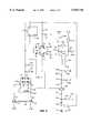
- FIG. 2is a schematic diagram of circuitry according to the invention that is located on the interior side of a window for transmitting electrical power to an external transmission line and for receiving video signals from the transmission line;
- FIG. 3is a schematic diagram of circuitry according to the invention that is located on the exterior side of a window for receiving electrical power for delivery to an external transmission line and for sending video signals from the transmission line to the circuitry of FIG. 2;
- FIG. 4graphically illustrates the amplitude of the RF signals transmitted from the external transmission line to the interior receiver
- FIG. 5is a schematic diagram of alternative circuitry for placement on the interior side of a window for transmitting electrical power to an external transmission line and for receiving video signals from the transmission line;
- FIG. 6is a schematic diagram of alternative circuitry for placement on the exterior side of a window for receiving electrical power for delivery to an external transmission line and for sending video signals from the transmission line to a receiver on the interior side of the window;
- FIG. 7illustrates an alternative arrangement of a transformer that may be included in the circuitry of FIGS. 2-6.
- an interface device 5has an indoors circuit 6 mounted to the interior surface of a window 34.
- the window 34may be a single thickness of glass or it may comprise two or more layers of glass, air or other dielectric material.
- An outdoors circuit 7 of the interface device 5is mounted to the exterior surface of the window 34 in predetermined alignment with the indoors circuit 6.
- a transmission line 8is connected between the indoors circuit 6 and a receiver 9, which is connected to a power source (not shown).
- a transmission line 10is connected between the outdoors circuit 7 and a satellite electronics unit 11, which is connected to an antenna 12 that is suitable for receiving video signals from a communications satellite (not shown) orbiting the earth.
- the interface device 5is formed to provide DC power from the receiver 9 and to provide broadband RF signals from the transmission line 10 to the receiver 9.
- the transmission line 10is exposed to radiation from sources (not shown) other than the antenna 12 and therefore conducts unwanted common mode signals to the outdoors circuit 7.
- the interface circuitalso provides rejection of common mode signals from these sources.
- the problem solved by the present inventionis providing RF signals from the outdoors transmission line 10 to the indoors transmission line 8 that is connected to the receiver 9 and providing electrical power from the indoors receiver 9 to the outdoors transmission line 10 for delivery to the satellite electronics 11.
- the outdoors portion 7 of the interface circuitry 5transmits broadband RF signals from the outdoors transmission line 10 through a window glass 34 to an indoors portion 6 of the interface circuit 5.
- the indoors portion 6 of the interface circuit 5is connected to a transmission line 8 that is connected to the indoors receiver 9.
- the indoors portion 6 of the interface circuittransmits electrical power from the indoors receiver 9 to the outdoors portion 7 of the interface circuit 5.
- the outdoors portion 7 of the interface circuitry 5provides the electrical power to the outdoors transmission line 10, which then conducts the DC power to the satellite electronics 11.
- FIGS. 2-7illustrate the principles of the present invention by showing specific interface circuitry for implementing the invention.
- Conventional TV satellite systemsrequire a power source capable of being switched between 12 VDC or 18 VDC. Signals from the satellite are divided into vertically polarized and horizontally polarized. The voltage provided to the satellite electronics determines whether signals carried by the vertical or horizontal polarization are to be sent to the receiver.
- the electrical power transmission according to the inventionmeets the power requirements of conventional TV satellite systems.
- the indoors interface sectionincludes an electrical conductor 14 that is connected to the coaxial cable 8.
- the coaxial cable 8is arranged to receive DC electrical power from the receiver 9 of FIG. 1.
- the DC electrical power from the receiver 9provides power for the interface circuitry described subsequently and for the outdoors satellite electronics 11, which is also shown in FIG. 1.
- the electrical powerthen flows from the coaxial cable 8 through the conductor 14 to an inductor 16.
- the inductor 16blocks RF signals from entering subsequent components of the power transmission circuitry.
- the inductor 16is connected to a conductor 18 at a junction 20.
- the indoors interface circuit section 6preferably is formed on a printed circuit board (not shown). It is convenient to form inductors having small inductances as lengths of a conductor on the printed circuit board.
- the inductor 16preferably has an inductance of about 20 nH and may be achieved by forming parallel sections of conductor on the printed circuit board. In FIGS. 2 and 3, printed circuit inductors are shown in the manner illustrated for the inductor 16. Wound conductor inductors are illustrated in the conventional manner.
- a voltage regulator 22is connected between the junction 20 and a +5 volt DC source.
- a capacitor 26is connected between the input of the voltage regulator 22 and ground to prevent AC noise from entering the voltage regulator 22.
- the capacitor 26preferably has a capacitance of about 0.1 mF.
- the output of the voltage regulator 22is connected to a capacitor 24, which also bypasses any AC noise in the output of the voltage regulator 22 to ground.
- a filter network that includes capacitors 28-30 and an inductor 31prevents switching transients from being coupled back to coaxial cable 8.
- the capacitors 28 and 30preferably each have a capacitance of about 3.3 mF, and the capacitor 29 preferably has a capacitance of about 0.1 mF.
- the inductor 31preferably has an inductance of about 1 mH.
- the filtered DC poweris then conducted to a tapped inductor 32, which has a movable core 33.
- the inductor 32is placed adjacent to the window 34.
- the ends of the inductor 32are connected to a capacitor 36 so that the inductor 32 and the capacitor 36 are in parallel.
- the capacitor 36preferably has a capacitance of about 1000 pF.
- the parallel combination of the inductor 32 and capacitor 36is connected to a MOSFET device 38 that converts the DC power input to the inductor 32 into an alternating magnetic field, which is then used to transmit the power across the gap created by the thickness of the glass 34 via magnetic induction.
- the exterior portion of the interface circuitry shown in FIG. 3includes an inductor 40 that is mounted adjacent the window glass 34. It should be noted that the window glass 34 remains intact with no holes or grooves being formed therein.
- the time-varying magnetic field produced by the inductor 32extends axially away from the coil that forms the inductor 32. In particular, the magnetic field produced by the inductor 32 extends to the region occupied by the inductor 40. The time-varying magnetic field produced by the inductor 32 induces a current in the inductor 40.
- the power transmission circuitrysends power across the dielectric gap to the transmission line 10 that is in turn connected to the electronics 11 for the antenna 12. Because of the dielectric gap, there is no continuous core for linking magnetic flux created in the primary inductor 32 to the inductor 40. Also because of inherent satellite system limitations in the power available, the coupling efficiency preferably is at least 60%. The circuitry in the power transmission system described subsequently describes how this efficiency is achieved at a level of approximately 4 watts across the glass gap.
- a capacitor 42is connected to a first end of the inductor 40.
- the other end of the inductor 40is connected to a conductor 44.
- the capacitor 42preferably has a capacitance of about 10000 pF.
- a diode network that includes diodes 50-53is connected across the series connected inductor 40 and capacitor 42. The output of the diode network is then filtered by a pair of capacitors 60 and 62 that preferably have capacitances of about 4.7 mF and 0.1 mF, respectively.
- the DC power from the diode arrayis delivered to a voltage regulator 70, which provides a regulated 5 VDC output.
- the output of the voltage regulator 70is input to a voltage level indicator that includes pair of transistors 72 and 74 that are arranged to form a comparator and a pair of light emitting diodes (LEDs) 64 and 66.
- the comparatoris arranged to compare the voltage output from the diode array with the 5 VDC regulator output.
- a resistor 76that preferably has a resistance of about 51 k ⁇ is connected between the base of the transistor 74 and ground.
- a resistor 78is connected between the base of the transistor 74 and the input of the voltage regulator 70. The resistors 76 and 78 set the comparison levels of the transistors 72 and 74.
- the resistors 76 and 78provide a voltage division of 3:1 so that when the output voltage from the power transfer circuit is 15 volts, the same voltage is applied to both transistors 72 and 74.
- the comparatorincludes resistors 80 and 82 connected between the emitters of the transistors 72 and 74 and ground.
- a resistor 86is connected between the emitters.
- the resistor 80 and 82preferably each have resistance's of about 2 k ⁇ .
- the resistor 86preferably has a resistance of about 100 ⁇ .
- the inductor core 33 positionis preset for a standard glass pane thickness, and ordinarily no adjustment of the core position is necessary. However, when the system is installed on the window 34, the installer may adjust the position of the core 33 of the inductor 32 so that the LEDs 64 and 66 brighten as desired to indicate the voltage.
- the LED 64may be formed to emit a bright green light when the system is in the 12 volt DC mode, which corresponds to either vertical or horizontal polarized signals from the satellite.
- the LED 66may emit a bright yellow light when the system is in the 18 volt DC mode, which corresponds to the other polarization.
- the output of the voltage regulator 70is also provides a bias voltage to an amplifier 98 that is included in the RF signal transmission circuitry.
- the electrical connection between the antenna electronics 11 and the interface circuitrypreferably is provided by a coaxial cable 10 as ordinarily used in such applications.
- An inductor 202that preferably has an inductance of about 20 nH is connected between the coaxial cable 10 and the voltage regulator 70 to provide a conducting path for the DC power that is delivered to the transmission line and then to the antenna electronics.
- the drive signalnormally requires the drive signal to operate at the resonant frequency which is dictated by inductor 40 and capacitor 42.
- the resonant frequencyis the frequency of maximum power transfer.
- the systemis preferably constructed to operate at a resonant frequency of about 60 kHz.
- the thickness of the glass, temperature fluctuations, component aging and other environmental factorscan cause the resonant frequency to deviate from the nominal 60 kHz value.
- the inventionincludes a feedback network to control the frequency into which the DC power is converted for input to the inductor 32 and transmission across the gap via magnetic induction.
- this feedback networkincludes a capacitive plate 100 connected to the capacitor 42 at a junction 103 and a capacitive plate 102 is connected to the inductor 40 at a junction 104.
- a plate 105is mounted adjacent the glass 34 opposite the plate 100, and a similar plate 107 is mounted to the glass 34 opposite the plate 102.
- the pairs of plates 100, 105 and 102, 107are arranged to provide a capacitive coupling across the dielectric glass 34.
- the capacitive coupling using the two sets of platesprovides a differentially balanced drive via terminals G101 and G102 to avoid sending back stray common mode noise signals to the feedback network.
- the signals at the terminals G101 and G102are input to an amplifier 110 shown in FIG. 2.
- the amplifier 110has a bias voltage source Vb connected to resistors 108 and 109 that are connected to the amplifier inputs G101 and G102, respectively.
- the feedback circuitrymay include a voltage divider (not shown) to scale the feedback signal to an amplitude appropriate for input to the amplifier 110.
- the voltages at G101 and G102are of equal magnitude and are 180° out of phase. Should the frequency deviate from resonance, a phase difference develops between the drive of inductor 32 and the feedback from G101 and G102.
- the amplifier 110is preferably a linear amplifier with differential input so that only feedback signals from the capacitors 100 and 102 are amplified.
- the differential inputs to the linear amplifier and resulting reinforcement of those in-phase signals at the resonant frequencyforms a circuit that oscillates at the resonant frequency of the reactive power transfer circuit. Even if the resonant frequency has deviated from its nominal 60 kHz value, the oscillator tracks the actual resonant frequency.
- the phase response of the feedback signal to the amplifier at the differential inputsinsures that oscillation will occur only at the actual resonant frequency even if it varies with temperature and other environmental parameters.
- the amplifier 110 and subsequent drive circuitryshould be very fast in order for the signal amplified to be free of phase errors at the resonance frequency at all times.
- the time delay between the input and output for the amplifier 110preferably is 200 nanoseconds or less.
- the maximum resulting phase erroris then less than 5°.
- the output of the amplifier 110is input to a resistor 112 that preferably has a resistance of about 2 k ⁇ .
- the signal input to the resistor 112is a rectangular wave that is an analog representation of the signal output by the inductor 40 and capacitor 42 to the load connected thereto.
- a resistor 116which preferably has a resistance of about 2 k ⁇ has one end connected to the resistor 112 at a junction 114. The other end of the resistor 116 is grounded.
- the power transfer circuitry 38When power is first applied to the interface circuit, there is no feedback signal and therefore no oscillatory input to the MOSFET circuitry 38. Absent a suitable signal input to the MOSFET circuitry 38, the power transfer circuitry will not function to convert the DC input to time-varying signals that can be transmitted from the inductor 32 to the inductor 40 via magnetic induction.
- the drive networkincludes a Schmitt trigger circuit 120 that is connected to the junction 114 through a capacitor 118 that preferably has a capacitance of about 470 pF.
- a resistor 122preferably having a resistance of about 51 k ⁇ is connected across the input and output of the Schmitt trigger circuit 120.
- the capacitance 118 and the resistor 122cooperate to cause the Schmitt trigger 120 to self-oscillate and produce a square wave at a frequency of about 60 kHz in the absence of a signal output from the amplifier 110.
- the 60 kHz output of the Schmitt trigger 120then is input to an inverter 124 whose output is connected to the input terminals of a pair of parallel-connected inverters 126 and 128.
- the output of the Schmitt trigger 120is also input directly to the input terminals of a second pair of parallel-connected inverters 130 and 132.
- the output signal from the inverters 126 and 128is input to a resistor 134 that preferably has a resistance of about 10 ⁇ . Signals that pass through the resistor 134 are input to a first MOSFET 140 in the MOSFET device 38.
- the output signal from the inverters 130 and 132is input to a resistor 142 that preferably has a resistance of about 10 ⁇ . Signals that pass through the resistor 142 are input to a second MOSFET 144 in the MOSFET device 38.
- the inverters 124, 126, 128, 130 and 132drive the MOSFETs 140 and 144 so that they are 180° out of phase. Therefore, the MOSFETs 140 and 144 form an electronic switch that alternately produces outputs of low and high resistance to ground. One MOSFET output is grounded while the other is open.
- the DC poweris applied to the center tap of the inductor 32 while its opposite ends alternate between ground potential and approximately twice the supply voltage to the center tap of inductor 32. Therefore, current through the inductor 32 varies with time, which allows transmission of power through the glass 34 via magnetic induction.
- the driver input signal from the Schmitt trigger 120 at start upturns the switches 140 and 144 on and off so that the MOSFETs convert the DC signal applied to the center tap of the inductor 32 into a 60 kHz square wave.
- the feedback signalis applied to the amplifier 110, the output of which is then used to phase lock the Schmitt trigger so that it produces an output that has the same frequency and phase as the signal output from the amplifier 110.
- the RF signal from the antenna electronics(not shown) is guided by the coaxial cable 10 as ordinarily used in such applications to the exterior portion of the interface circuit according to the invention.
- a capacitor 204that preferably has a capacitance of about 100 pF is connected to the coaxial cable 10 for coupling the RF signals from the coaxial cable 10 into the interface circuit.
- a resistor 212 that preferably has a resistance of about 20 ⁇is connected to the capacitor 204 at a junction 206 and to the input of the amplifier 98.
- a resistor 208 that preferably has a resistance of about 82 ⁇is connected between the junction 206 and a first terminal of a capacitor 210 that preferably has a capacitance of about 0.1 mF. The other terminal of the capacitor 210 is grounded.
- the resistors 208 and 212are matching resistors that match the impedance of the amplifier 98 to the coaxial cable 10.
- the amplifier 98preferably has input and output impedances of 50 ⁇ .
- the capacitor RF output of the amplifier 98passes through a capacitor 216 that preferably has a capacitance of about 100 pF.
- a resistor 224 that preferably has a resistance of about 20 ⁇is connected to the capacitor 216 at a junction 218.
- a resistor 220 that preferably has a resistance of about 300 ⁇is connected between the junction 218 and ground.
- Another resistor 228 that preferably has a resistance of about 300 ⁇has a first end connected to a junction 226 that is connected the output of the resistor 224. The other end of the resistor 228 is grounded.
- the three resistors 220, 224 and 228together form a ⁇ -attenuator that isolates the effects of resonances and reactive loads on the amplifier 98.
- the RF signalsnext enter a balun 230 that converts the unbalanced feed from the amplifier 98 into a differentially balanced feed.
- the present inventionis designed to guide RF signals from the coaxial cable 10 to the receiver 9 while suppressing unwanted common mode signals that may be picked up from radiation sources other than the antenna 12.
- the coaxial cable 10is typically a long cable that can act like an antenna that picks up unwanted signals.
- the differentially balanced output of the balun 230is applied across an inductor 240 that preferably has an inductance of about 12 nH.
- the circuitincludes grounded capacitors 234 and 238 connected to the opposite ends of the inductor 240. These capacitors may be formed as physical structures on the printed circuit board.
- the differentially balanced feedprovides maximum rejection of common mode signals.
- An inductor 242has one terminal connected to the junction of a first terminal of the balun 230, the capacitor 234 and the inductor 240. The other terminal of the inductor 242 is connected to a plate 246 that is located adjacent to the window glass 34.
- an inductor 244has one terminal connected to the other output of the balun, the capacitor 238 and the inductor 240. The other terminal of the inductor 244 is connected to a plate 248 that is also located adjacent the window glass.
- plates 250 and 254are located adjacent the window glass opposite the plates 246 and 248, respectively.
- the opposing pairs of plates 246, 250 and 248, 254form capacitors that couple the differentially balanced RF signals through the glass 34.
- RF signals from the plate 250pass through an inductor 252 that preferably has an inductance of about 4.5 nH to a first input terminal of a balun 262.
- RF signals from the plate 254pass through an inductor 256 that also preferably has an inductance of about 4.5 nH to a second input terminal of the balun 262.
- An inductor 258that preferably has an inductance of about 12 nH is connected across the outputs of the two inductors 252 and 256.
- a grounded capacitor 260is connected to the first input terminal of the balun 262, and a grounded capacitor 261 may be connected to the second input terminal of the balun 262.
- the various reactive components of the circuitry together with the capacitance of the plates attached to the glassserve to generate a circuit having an essentially flat passband and low losses in the frequency range of about 900 to 1500 MHz.
- Signals output from the balun 262are applied to a junction 264 where a pair of resistors 266 and 268 are connected.
- the resistor 266is grounded.
- the resistor 266preferably has a resistance of about 82 ⁇ while the resistor 268 preferably has a resistance of about 43 ⁇ . These resistance's are chosen to match the output impedance of the circuitry to the 75 ⁇ impedance of the coaxial cable 8, which is connected to the resistor 268 through a capacitor 270 that preferably has a capacitance of about 100 pF.
- the transformer 262 of FIG. 2may be replaced by a differential amplifier 279 that includes a pair of transistors 280 and 282.
- the amplifier 279is biased to operate in its linear region.
- One of the purposes of the amplifier 279is to offset losses in the RF signal transmission path. These losses typically are about 21 dB and are mainly caused by the dielectric gap of the window 34.
- the resistor 268is connected to the collector of the transistor 282 and to a first terminal of a resistor 286.
- the other terminal of the resistor 286is connected to a voltage source V S , which is about +5 volts, and to the collector of the transistor 280.
- the resistor 286is therefore connected between the collectors of the two transistors 280 and 282.
- the output of the amplifier 279is taken off the collector of the transistor 282.
- the base of the transistor 280is connected to the junction of the capacitor 260 and the inductors 252 and 258.
- the emitters of the transistors 280 and 282are connected together and also connected to a first terminal of a resistor 284.
- the other terminal of the resistor 284is grounded.
- the resistor 284is a current source resistor and may be replaced by a constant current source.
- the base of the transistor 282is connected to the junction of the capacitor 261, the inductor 258 and the inductor 256.
- a resistor 290is connected between the bases of the two transistors 280 and 282. The remaining circuitry of FIG. 5 is identical to that of FIG. 2.
- the differential feeding of the RF signal from the plates 250 and 254 to the amplifier 279 of FIG. 5 (or to the balun 262 of FIG. 2)provides the capability of transmitting a broadband RF signal with a single set of electrodes.
- Prior art circuitry for transmitting RF signals through a dielectricoperate efficiently only at a single frequency and are inherently narrow-band.
- the amplifier 98, the transformer 230 and the circuitry between themmay be replaced by a differential amplifier 299 that includes a pair of transistors 300 and 302.
- the amplifier 299is biased to operate in its linear region.
- One of the purposes of the amplifier 279is to offset losses in the RF signal transmission path.
- the approximate 21 dB signal lossmay be offset entirely by circuitry that includes one of the differential amplifiers 279 and 299.
- the circuitrymay include both of the differential amplifiers 279 and 299 so that the gain necessary for offsetting the losses may be divided between the two amplifiers 279 and 299. Using both amplifiers 279 and 299 causes a decrease in the signal to noise ratio of the circuitry, but permits the use of less expensive transistors.
- the base of the transistor 300is connected to the resistor 212.
- the emitters of the transistors 300 and 302are connected together and also connected to a first terminal of a resistor 308.
- the resistor 308is a current source resistor and may be replaced by a constant current source.
- the other terminal of the resistor 308is grounded.
- the collector of the transistor 300is connected to a first terminal of a resistor 304.
- the other terminal of the resistor 304is connected to the output VO of the voltage regulator 70.
- a resistor 306is also connected to the VO output of the voltage regulator 70 and to the collector of the transistor 302.
- the output resistors 304 and 306preferably have resistances of about 25 ⁇ so that the resistance between the collectors of the transistors 300 and 302 is 50 ⁇ .
- the collector of the transistor 300is connected junction 236 of the capacitor 238 and the inductor 240.
- the collector of the transistor 302is connected to the junction 232 of the capacitor 234 and the in
- FIG. 7illustrates an alternative transformer 320 that may be used instead of the transformer 262.
- the terminals of the transformers 262 and 320are labeled 1-4.
- the transformer 320may be inserted instead of the transformer 262 by keeping the terminal numbering the same in the circuitry of FIG. 2.
- the differential signalis input across the terminals 3 and 4.
- the single ended outputis taken at terminal 1 with terminal 2 of the transformer 320 being grounded.
- the transformer 320may be similarly substituted for the transformer 230 of FIG. 3.
Landscapes
- Engineering & Computer Science (AREA)
- Signal Processing (AREA)
- Multimedia (AREA)
- Computer Networks & Wireless Communication (AREA)
- Physics & Mathematics (AREA)
- Astronomy & Astrophysics (AREA)
- General Physics & Mathematics (AREA)
- Amplifiers (AREA)
- Near-Field Transmission Systems (AREA)
- Input Circuits Of Receivers And Coupling Of Receivers And Audio Equipment (AREA)
Abstract
Description
Claims (26)
Priority Applications (1)
| Application Number | Priority Date | Filing Date | Title |
|---|---|---|---|
| US08/818,888US5929718A (en) | 1996-03-04 | 1997-03-17 | Apparatus and method for transmitting electrical power and broadband RF communications signals through a dielectric |
Applications Claiming Priority (2)
| Application Number | Priority Date | Filing Date | Title |
|---|---|---|---|
| US08/610,327US5612652A (en) | 1996-03-04 | 1996-03-04 | Apparatus for transmitting electrical power and broadband communications signals through a dielectric |
| US08/818,888US5929718A (en) | 1996-03-04 | 1997-03-17 | Apparatus and method for transmitting electrical power and broadband RF communications signals through a dielectric |
Related Parent Applications (1)
| Application Number | Title | Priority Date | Filing Date |
|---|---|---|---|
| US08/610,327Continuation-In-PartUS5612652A (en) | 1996-03-04 | 1996-03-04 | Apparatus for transmitting electrical power and broadband communications signals through a dielectric |
Publications (1)
| Publication Number | Publication Date |
|---|---|
| US5929718Atrue US5929718A (en) | 1999-07-27 |
Family
ID=24444595
Family Applications (2)
| Application Number | Title | Priority Date | Filing Date |
|---|---|---|---|
| US08/610,327Expired - LifetimeUS5612652A (en) | 1996-03-04 | 1996-03-04 | Apparatus for transmitting electrical power and broadband communications signals through a dielectric |
| US08/818,888Expired - LifetimeUS5929718A (en) | 1996-03-04 | 1997-03-17 | Apparatus and method for transmitting electrical power and broadband RF communications signals through a dielectric |
Family Applications Before (1)
| Application Number | Title | Priority Date | Filing Date |
|---|---|---|---|
| US08/610,327Expired - LifetimeUS5612652A (en) | 1996-03-04 | 1996-03-04 | Apparatus for transmitting electrical power and broadband communications signals through a dielectric |
Country Status (3)
| Country | Link |
|---|---|
| US (2) | US5612652A (en) |
| TW (1) | TW305092B (en) |
| WO (1) | WO1997033336A1 (en) |
Cited By (17)
| Publication number | Priority date | Publication date | Assignee | Title |
|---|---|---|---|---|
| US6087787A (en)* | 1998-11-23 | 2000-07-11 | Linear Technology Corporation | Fluorescent-lamp excitation circuit with frequency and amplitude control and methods for using same |
| US6420923B1 (en) | 2000-07-12 | 2002-07-16 | Motorola, Inc. | Low supply, current-controlled FET Pi attenuator |
| US6538609B2 (en) | 1999-11-10 | 2003-03-25 | Xm Satellite Radio Inc. | Glass-mountable antenna system with DC and RF coupling |
| US6686882B2 (en) | 2000-10-19 | 2004-02-03 | Xm Satellite Radio, Inc. | Apparatus and method for transferring DC power and RF energy through a dielectric for antenna reception |
| US6915529B1 (en)* | 1998-02-27 | 2005-07-05 | Sharp Kabushiki Kaisha | Milliwave transmitting device, milliwave receiving device and milliwave transmission and reception system capable of simplifying wiring of a receiving system of terrestrial broadcasting service and satellite broadcasting service |
| US20060062515A1 (en)* | 2004-09-22 | 2006-03-23 | Kamran Mahbobi | Apparatus and method for transmitting electrical power through a transparent or substantially transparent medium |
| US20060062580A1 (en)* | 2004-09-22 | 2006-03-23 | Kamran Mahbobi | Apparatus and method for transferring DC power and RF signals through a transparent or substantially transparent medium for antenna reception |
| US20080274691A1 (en)* | 2007-05-02 | 2008-11-06 | John Mezzalingua Associates, Inc. | Cable System with Active RF Device Powered by RF Energy Converted to DC Power, and Associated Method |
| US7504905B1 (en) | 2008-01-30 | 2009-03-17 | The United States Of America As Represented By The Secretary Of The Navy | Method for coupling a direct current power source across a dielectric membrane or other non-conducting membrane |
| US20090167626A1 (en)* | 2007-12-28 | 2009-07-02 | Henry Gregg Martch | Apparatus and systems for electrically isolating a receiver from an antenna |
| US7558553B1 (en) | 2000-12-21 | 2009-07-07 | Cisco Technology, Inc. | Advance signaling for multi-stage tranceivers |
| WO2009089146A1 (en)* | 2008-01-04 | 2009-07-16 | Powercast Corporation | Power transmission by electric field |
| US20110047588A1 (en)* | 2009-08-21 | 2011-02-24 | Sony Corporation | Wired transmission line for AV devices |
| US20120071094A1 (en)* | 2010-09-20 | 2012-03-22 | Brendan Peter Hyland | Communication through a composite barrier |
| EP2485324A1 (en)* | 2011-02-04 | 2012-08-08 | Raytheon Company | System for Transferring Power and/or Data Through a Non-Ferrous Skin of a Vehicle |
| EP2223222A4 (en)* | 2007-11-16 | 2017-08-16 | Qualcomm Incorporated | Wireless power bridge |
| US20200204212A1 (en)* | 2018-12-20 | 2020-06-25 | Arris Enterprises Llc | Last meter wireless broadband |
Families Citing this family (15)
| Publication number | Priority date | Publication date | Assignee | Title |
|---|---|---|---|---|
| TW305092B (en)* | 1996-03-04 | 1997-05-11 | Multiplex Technology Inc | Apparatus and method for transmitting electrical power and broadband RF communications signals through a dielectric |
| US6134420A (en)* | 1996-11-01 | 2000-10-17 | Plantronics, Inc. | Vector measuring aerial arrays for magnetic induction communication systems |
| US6061030A (en)* | 1996-11-01 | 2000-05-09 | Plantronics, Inc. | Aerial arrays for magnetic induction communication systems having limited power supplies |
| US6463089B1 (en) | 1998-08-19 | 2002-10-08 | Interair Wireless, Inc. | Hybrid spread spectrum method and system for wirelessly transmitting and receiving wideband digital data |
| US7228429B2 (en)* | 2001-09-21 | 2007-06-05 | E-Watch | Multimedia network appliances for security and surveillance applications |
| JP2000114609A (en)* | 1998-10-07 | 2000-04-21 | Fujitsu Ltd | Insulated bath, constant temperature bath and cryostat |
| DE19858299A1 (en)* | 1998-12-17 | 2000-06-29 | Daimler Chrysler Ag | Antenna system for a data communication device in a vehicle |
| DE19934867A1 (en)* | 1999-07-24 | 2001-02-15 | Bosch Gmbh Robert | Glass adhesive antenna |
| JP2002124806A (en)* | 2000-10-13 | 2002-04-26 | Mitsumi Electric Co Ltd | Signal transmission circuit |
| EP1556087A2 (en)* | 2002-10-31 | 2005-07-27 | Pfizer Products Inc. | Liquid conjugates of solid pharmaceuticals |
| JP2007512796A (en)* | 2003-10-17 | 2007-05-17 | ファイアフライ パワー テクノロジーズ,インコーポレイテッド | Method and apparatus for supplying power wirelessly |
| JP4604094B2 (en)* | 2008-01-23 | 2010-12-22 | トヨタ自動車株式会社 | Vehicle power supply device and vehicle window material |
| US8988295B2 (en)* | 2011-09-19 | 2015-03-24 | Laird Technologies, Inc. | Multiband antenna assemblies with matching networks |
| US12021315B2 (en) | 2019-03-22 | 2024-06-25 | Commscope Technologies Llc | Dual-polarized radiating elements for base station antennas having built-in common-mode rejection filters that block common mode radiation parasitics |
| WO2020197849A1 (en)* | 2019-03-22 | 2020-10-01 | Commscope Technologies Llc | Dual-polarized radiating elements for base station antennas having built-in stalk filters that block common mode radiation parasitics |
Citations (17)
| Publication number | Priority date | Publication date | Assignee | Title |
|---|---|---|---|---|
| US4109214A (en)* | 1977-05-31 | 1978-08-22 | Motorola, Inc. | Unbalanced-to-balanced signal converter circuit |
| US4238199A (en)* | 1977-01-26 | 1980-12-09 | Deutsche Gold- Und Silber-Scheideanstalt Vormals Roessler | Process for the control of the ratio DBP number/DBP number after pressing in the manufacture of carbon black pellets |
| US4764773A (en)* | 1985-07-30 | 1988-08-16 | Larsen Electronics, Inc. | Mobile antenna and through-the-glass impedance matched feed system |
| US4794319A (en)* | 1986-07-03 | 1988-12-27 | Alliance Research Corporation | Glass mounted antenna |
| US4825217A (en)* | 1987-10-19 | 1989-04-25 | Tae Lim Electronics Co., Ltd. | Car phone antenna assembly |
| US4916456A (en)* | 1989-05-12 | 1990-04-10 | Don Shyu | Glass-mountable antenna assembly |
| US5057847A (en)* | 1989-05-22 | 1991-10-15 | Nokia Mobile Phones Ltd. | Rf connector for connecting a mobile radiotelephone to a rack |
| US5105201A (en)* | 1989-06-30 | 1992-04-14 | Harada Kogyo Kabushiki Kaisha | Glass mounted antenna for car radio |
| US5134486A (en)* | 1990-07-27 | 1992-07-28 | Sony Corporation | Television set with satellite broadcast receiver |
| US5161255A (en)* | 1990-01-26 | 1992-11-03 | Pioneer Electronic Corporation | Motor vehicle-mounted radio wave receiving gps apparatus requiring no drill holes for mounting |
| US5212492A (en)* | 1990-04-09 | 1993-05-18 | Andrew Jesman | Matching element for mobile antenna |
| US5278572A (en)* | 1990-11-01 | 1994-01-11 | Harada Kogyo Kabushiki Kaisha | Antenna coupling circuit using capacitive coupling |
| US5298907A (en)* | 1992-06-29 | 1994-03-29 | Alliance Research Corporation | Balanced polarization diversified cellular antenna |
| US5422681A (en)* | 1992-03-30 | 1995-06-06 | Sony Corporation | Satellite broadcast receiving apparatus capable of forming co-distributing system |
| US5451966A (en)* | 1994-09-23 | 1995-09-19 | The Antenna Company | Ultra-high frequency, slot coupled, low-cost antenna system |
| US5557290A (en)* | 1992-12-16 | 1996-09-17 | Daiichi Denpa Kogyo Kabushiki Kaisha | Coupling apparatus between coaxial cables and antenna system using the coupling apparatus |
| US5612652A (en)* | 1996-03-04 | 1997-03-18 | Multiplex Technology, Inc. | Apparatus for transmitting electrical power and broadband communications signals through a dielectric |
Family Cites Families (2)
| Publication number | Priority date | Publication date | Assignee | Title |
|---|---|---|---|---|
| US4238799A (en)* | 1978-03-27 | 1980-12-09 | Avanti Research & Development, Inc. | Windshield mounted half-wave communications antenna assembly |
| JP2509457B2 (en)* | 1992-12-16 | 1996-06-19 | 第一電波工業株式会社 | Coaxial cable coupling device and antenna device |
- 1996
- 1996-03-02TWTW085102548Apatent/TW305092B/enactive
- 1996-03-04USUS08/610,327patent/US5612652A/ennot_activeExpired - Lifetime
- 1997
- 1997-03-03WOPCT/US1997/003250patent/WO1997033336A1/enactiveApplication Filing
- 1997-03-17USUS08/818,888patent/US5929718A/ennot_activeExpired - Lifetime
Patent Citations (17)
| Publication number | Priority date | Publication date | Assignee | Title |
|---|---|---|---|---|
| US4238199A (en)* | 1977-01-26 | 1980-12-09 | Deutsche Gold- Und Silber-Scheideanstalt Vormals Roessler | Process for the control of the ratio DBP number/DBP number after pressing in the manufacture of carbon black pellets |
| US4109214A (en)* | 1977-05-31 | 1978-08-22 | Motorola, Inc. | Unbalanced-to-balanced signal converter circuit |
| US4764773A (en)* | 1985-07-30 | 1988-08-16 | Larsen Electronics, Inc. | Mobile antenna and through-the-glass impedance matched feed system |
| US4794319A (en)* | 1986-07-03 | 1988-12-27 | Alliance Research Corporation | Glass mounted antenna |
| US4825217A (en)* | 1987-10-19 | 1989-04-25 | Tae Lim Electronics Co., Ltd. | Car phone antenna assembly |
| US4916456A (en)* | 1989-05-12 | 1990-04-10 | Don Shyu | Glass-mountable antenna assembly |
| US5057847A (en)* | 1989-05-22 | 1991-10-15 | Nokia Mobile Phones Ltd. | Rf connector for connecting a mobile radiotelephone to a rack |
| US5105201A (en)* | 1989-06-30 | 1992-04-14 | Harada Kogyo Kabushiki Kaisha | Glass mounted antenna for car radio |
| US5161255A (en)* | 1990-01-26 | 1992-11-03 | Pioneer Electronic Corporation | Motor vehicle-mounted radio wave receiving gps apparatus requiring no drill holes for mounting |
| US5212492A (en)* | 1990-04-09 | 1993-05-18 | Andrew Jesman | Matching element for mobile antenna |
| US5134486A (en)* | 1990-07-27 | 1992-07-28 | Sony Corporation | Television set with satellite broadcast receiver |
| US5278572A (en)* | 1990-11-01 | 1994-01-11 | Harada Kogyo Kabushiki Kaisha | Antenna coupling circuit using capacitive coupling |
| US5422681A (en)* | 1992-03-30 | 1995-06-06 | Sony Corporation | Satellite broadcast receiving apparatus capable of forming co-distributing system |
| US5298907A (en)* | 1992-06-29 | 1994-03-29 | Alliance Research Corporation | Balanced polarization diversified cellular antenna |
| US5557290A (en)* | 1992-12-16 | 1996-09-17 | Daiichi Denpa Kogyo Kabushiki Kaisha | Coupling apparatus between coaxial cables and antenna system using the coupling apparatus |
| US5451966A (en)* | 1994-09-23 | 1995-09-19 | The Antenna Company | Ultra-high frequency, slot coupled, low-cost antenna system |
| US5612652A (en)* | 1996-03-04 | 1997-03-18 | Multiplex Technology, Inc. | Apparatus for transmitting electrical power and broadband communications signals through a dielectric |
Cited By (31)
| Publication number | Priority date | Publication date | Assignee | Title |
|---|---|---|---|---|
| US6915529B1 (en)* | 1998-02-27 | 2005-07-05 | Sharp Kabushiki Kaisha | Milliwave transmitting device, milliwave receiving device and milliwave transmission and reception system capable of simplifying wiring of a receiving system of terrestrial broadcasting service and satellite broadcasting service |
| US20050177854A1 (en)* | 1998-02-27 | 2005-08-11 | Sharp Kabushiki Kaisha | Milliwave transmitting device, milliwave receiving device and milliwave transmission and reception system capable of simplifying wiring of a receiving system of terrestrial broadcasting service and satellite broadcasting service |
| US6087787A (en)* | 1998-11-23 | 2000-07-11 | Linear Technology Corporation | Fluorescent-lamp excitation circuit with frequency and amplitude control and methods for using same |
| US6538609B2 (en) | 1999-11-10 | 2003-03-25 | Xm Satellite Radio Inc. | Glass-mountable antenna system with DC and RF coupling |
| US6420923B1 (en) | 2000-07-12 | 2002-07-16 | Motorola, Inc. | Low supply, current-controlled FET Pi attenuator |
| US6686882B2 (en) | 2000-10-19 | 2004-02-03 | Xm Satellite Radio, Inc. | Apparatus and method for transferring DC power and RF energy through a dielectric for antenna reception |
| US7558553B1 (en) | 2000-12-21 | 2009-07-07 | Cisco Technology, Inc. | Advance signaling for multi-stage tranceivers |
| US7787900B1 (en) | 2000-12-21 | 2010-08-31 | Cisco Technology, Inc. | Advanced signaling for multi-stage transceivers |
| US20060062580A1 (en)* | 2004-09-22 | 2006-03-23 | Kamran Mahbobi | Apparatus and method for transferring DC power and RF signals through a transparent or substantially transparent medium for antenna reception |
| US7079722B2 (en) | 2004-09-22 | 2006-07-18 | Maxentric Technologies Llc | Apparatus and method for transmitting electrical power through a transparent or substantially transparent medium |
| US20060062515A1 (en)* | 2004-09-22 | 2006-03-23 | Kamran Mahbobi | Apparatus and method for transmitting electrical power through a transparent or substantially transparent medium |
| US8078102B2 (en) | 2007-05-02 | 2011-12-13 | John Mezzalingua Associates, Inc. | Cable system with active RF device powered by RF energy converted to DC power, and associated method |
| US20080274691A1 (en)* | 2007-05-02 | 2008-11-06 | John Mezzalingua Associates, Inc. | Cable System with Active RF Device Powered by RF Energy Converted to DC Power, and Associated Method |
| US9966188B2 (en) | 2007-11-16 | 2018-05-08 | Qualcomm Incorporated | Wireless power bridge |
| EP2223222A4 (en)* | 2007-11-16 | 2017-08-16 | Qualcomm Incorporated | Wireless power bridge |
| US7856207B2 (en) | 2007-12-28 | 2010-12-21 | Echostar Technologies L.L.C. | Apparatus and systems for electrically isolating and transmitting RF signals between two devices |
| US8170479B2 (en) | 2007-12-28 | 2012-05-01 | Echostar Technologies L.L.C. | Apparatus and systems for electrically isolating multiple devices |
| US7899395B2 (en) | 2007-12-28 | 2011-03-01 | Echostar Technologies L.L.C. | Apparatus and systems for electrically isolating a receiver from an antenna |
| US20110059695A1 (en)* | 2007-12-28 | 2011-03-10 | Echostar Technologies L.L.C. | Apparatus and systems for electrically isolating multiple devices |
| US20090167626A1 (en)* | 2007-12-28 | 2009-07-02 | Henry Gregg Martch | Apparatus and systems for electrically isolating a receiver from an antenna |
| WO2009089146A1 (en)* | 2008-01-04 | 2009-07-16 | Powercast Corporation | Power transmission by electric field |
| US7504905B1 (en) | 2008-01-30 | 2009-03-17 | The United States Of America As Represented By The Secretary Of The Navy | Method for coupling a direct current power source across a dielectric membrane or other non-conducting membrane |
| CN101997150A (en)* | 2009-08-21 | 2011-03-30 | 索尼公司 | Wired transmission line for AV devices |
| US8519804B2 (en)* | 2009-08-21 | 2013-08-27 | Sony Corporation | Wired transmission line for electromagnetic coupling of first and second millimeter wave AV devices |
| CN101997150B (en)* | 2009-08-21 | 2014-08-20 | 索尼公司 | Wired transmission line for AV devices |
| US20110047588A1 (en)* | 2009-08-21 | 2011-02-24 | Sony Corporation | Wired transmission line for AV devices |
| US20120071094A1 (en)* | 2010-09-20 | 2012-03-22 | Brendan Peter Hyland | Communication through a composite barrier |
| EP2485324A1 (en)* | 2011-02-04 | 2012-08-08 | Raytheon Company | System for Transferring Power and/or Data Through a Non-Ferrous Skin of a Vehicle |
| EP2485323A1 (en)* | 2011-02-04 | 2012-08-08 | Raytheon Company | System for transferring power and/or data through a non-ferrous skin of a vehicle |
| US8618898B2 (en) | 2011-02-04 | 2013-12-31 | Raytheon Company | System for transferring power and/or data through a non-ferrous skin of a vehicle |
| US20200204212A1 (en)* | 2018-12-20 | 2020-06-25 | Arris Enterprises Llc | Last meter wireless broadband |
Also Published As
| Publication number | Publication date |
|---|---|
| TW305092B (en) | 1997-05-11 |
| US5612652A (en) | 1997-03-18 |
| WO1997033336A1 (en) | 1997-09-12 |
Similar Documents
| Publication | Publication Date | Title |
|---|---|---|
| US5929718A (en) | Apparatus and method for transmitting electrical power and broadband RF communications signals through a dielectric | |
| KR100270793B1 (en) | Coupling device and antenna device of coaxial cable | |
| EP0992118B1 (en) | Transmission of fm video signals over various lines | |
| US4912553A (en) | Wideband video system for single power line communications | |
| US9071339B2 (en) | Closed-circuit power line communication | |
| US7277675B2 (en) | Array for the contact-less transmission of electrical signals or energy | |
| US6130645A (en) | Combination wide band antenna and heating element on a window of a vehicle | |
| US6862196B2 (en) | Integrated switch with RF transformer control | |
| JP7592747B2 (en) | Impedance matching circuit and plasma power supply system and method for operating | |
| EP1500211B1 (en) | Adapter for communicating over power line | |
| US5079399A (en) | High-frequency induction heating apparatus | |
| US6639947B1 (en) | EMI reduction for isolated bus systems | |
| US7079196B2 (en) | Television tuner which operates at low voltage | |
| AU603047B2 (en) | Improvements in or relating to cordless telephones | |
| KR960011159B1 (en) | High frequency planar transformer formed by wiring extending on an insulated substrate | |
| JP2005536911A (en) | Low frequency radio transmitter for automobile passive entry system | |
| WO2008033006A1 (en) | System for communicating with a responder | |
| US7395028B2 (en) | Switching apparatus and satellite antenna switching apparatus | |
| US7085545B2 (en) | Transmission power control circuit | |
| JPH05227050A (en) | Antenna input circuit for radio receiver | |
| JPS6336168B2 (en) | ||
| KR880000079B1 (en) | Oscillation Voltage and Tuning Voltage Supply Circuit of Satellite Receiver | |
| KR0137047Y1 (en) | Oscillation circuit using surface acoustic wave resonator | |
| JPS6190535A (en) | Commercial power line carrier communication equipment | |
| US20040070463A1 (en) | Voltage-controlled oscillator |
Legal Events
| Date | Code | Title | Description |
|---|---|---|---|
| AS | Assignment | Owner name:MULTIPLEX TECHNOLOGY, INC., CALIFORNIA Free format text:ASSIGNMENT OF ASSIGNORS INTEREST;ASSIGNOR:CROSBY, JOHN B.;REEL/FRAME:008450/0591 Effective date:19970313 | |
| STCF | Information on status: patent grant | Free format text:PATENTED CASE | |
| FPAY | Fee payment | Year of fee payment:4 | |
| AS | Assignment | Owner name:FLEET CAPITAL CORPORATION, NEW YORK Free format text:SECURITY INTEREST;ASSIGNORS:NORTEK, INC.;BROAN-NUTONE LLC, LIMITED LIABILITY COMPANY - DELAWARE;NUTONE INC., CORPORATION - DELAWARE;AND OTHERS;REEL/FRAME:013516/0374 Effective date:20020725 Owner name:FLEET CAPITAL CANADA CORPORATION, CANADA Free format text:SECURITY INTEREST;ASSIGNORS:NORTEK, INC.;BROAN-NUTONE LLC, LIMITED LIABILITY COMPANY - DELAWARE;NUTONE INC., CORPORATION - DELAWARE;AND OTHERS;REEL/FRAME:013516/0374 Effective date:20020725 | |
| AS | Assignment | Owner name:BROAN-NUTONE LLC, WISCONSIN Free format text:RELEASE AND REASSIGNMENT;ASSIGNORS:FLEET CAPITAL CORPORATION;FLEET CAPITAL CANADA CORPORATION;REEL/FRAME:015908/0223 Effective date:20040827 Owner name:ELAN HOME SYSTEMS, L.L.C., KENTUCKY Free format text:RELEASE AND REASSIGNMENT;ASSIGNORS:FLEET CAPITAL CORPORATION;FLEET CAPITAL CANADA CORPORATION;REEL/FRAME:015908/0223 Effective date:20040827 Owner name:JENSEN INDUSTRIES, INC., CALIFORNIA Free format text:RELEASE AND REASSIGNMENT;ASSIGNORS:FLEET CAPITAL CORPORATION;FLEET CAPITAL CANADA CORPORATION;REEL/FRAME:015908/0223 Effective date:20040827 Owner name:LINEAR LLC, CALIFORNIA Free format text:RELEASE AND REASSIGNMENT;ASSIGNORS:FLEET CAPITAL CORPORATION;FLEET CAPITAL CANADA CORPORATION;REEL/FRAME:015908/0223 Effective date:20040827 Owner name:MAMMOTH, INC., MINNESOTA Free format text:RELEASE AND REASSIGNMENT;ASSIGNORS:FLEET CAPITAL CORPORATION;FLEET CAPITAL CANADA CORPORATION;REEL/FRAME:015908/0223 Effective date:20040827 Owner name:MULTIPLEX TECHNOLOGY, INC., CALIFORNIA Free format text:RELEASE AND REASSIGNMENT;ASSIGNORS:FLEET CAPITAL CORPORATION;FLEET CAPITAL CANADA CORPORATION;REEL/FRAME:015908/0223 Effective date:20040827 Owner name:NORDYNE INC., MISSOURI Free format text:RELEASE AND REASSIGNMENT;ASSIGNORS:FLEET CAPITAL CORPORATION;FLEET CAPITAL CANADA CORPORATION;REEL/FRAME:015908/0223 Effective date:20040827 Owner name:NUTONE INC., OHIO Free format text:RELEASE AND REASSIGNMENT;ASSIGNORS:FLEET CAPITAL CORPORATION;FLEET CAPITAL CANADA CORPORATION;REEL/FRAME:015908/0223 Effective date:20040827 Owner name:SPEAKERCRAFT, INC., CALIFORNIA Free format text:RELEASE AND REASSIGNMENT;ASSIGNORS:FLEET CAPITAL CORPORATION;FLEET CAPITAL CANADA CORPORATION;REEL/FRAME:015908/0223 Effective date:20040827 Owner name:VENNAR VENTILATION, INC., CANADA Free format text:RELEASE AND REASSIGNMENT;ASSIGNORS:FLEET CAPITAL CORPORATION;FLEET CAPITAL CANADA CORPORATION;REEL/FRAME:015908/0223 Effective date:20040827 Owner name:XANTECH CORPORATION, CALIFORNIA Free format text:RELEASE AND REASSIGNMENT;ASSIGNORS:FLEET CAPITAL CORPORATION;FLEET CAPITAL CANADA CORPORATION;REEL/FRAME:015908/0223 Effective date:20040827 Owner name:UBS AG, STAMFORD BRANCH, AS U.S. ADMINISTRATIVE AG Free format text:SECURITY INTEREST;ASSIGNORS:BROAN-NUTONE LLC;ELAN HOME SYSTEMS, L.L.C.;JENSEN INDUSTRIES, INC.;AND OTHERS;REEL/FRAME:015918/0359 Effective date:20040827 | |
| AS | Assignment | Owner name:LINEAR LLC, CALIFORNIA Free format text:MERGER;ASSIGNOR:MULTIPLEX TECHNOLOGY, INC.;REEL/FRAME:017468/0980 Effective date:20051214 | |
| REMI | Maintenance fee reminder mailed | ||
| AS | Assignment | Owner name:LINEAR LLC, CALIFORNIA Free format text:STATEMENT OF INFORMATION;ASSIGNOR:LINEAR LLC;REEL/FRAME:019181/0384 Effective date:20060320 | |
| FPAY | Fee payment | Year of fee payment:8 | |
| SULP | Surcharge for late payment | Year of fee payment:7 | |
| AS | Assignment | Owner name:SPEAKERCRAFT, INC., CALIFORNIA Free format text:RELEASE OF SECURITY INTEREST IN INTELLECTUAL PROPERTY;ASSIGNOR:UBS AG, STAMFORD BRANCH, AS U.S. ADMINISTRATIVE AGENT;REEL/FRAME:021118/0548 Effective date:20080520 Owner name:XANTECH CORPORATION, CALIFORNIA Free format text:RELEASE OF SECURITY INTEREST IN INTELLECTUAL PROPERTY;ASSIGNOR:UBS AG, STAMFORD BRANCH, AS U.S. ADMINISTRATIVE AGENT;REEL/FRAME:021118/0548 Effective date:20080520 Owner name:NORTEK, INC., RHODE ISLAND Free format text:RELEASE OF SECURITY INTEREST IN INTELLECTUAL PROPERTY;ASSIGNOR:UBS AG, STAMFORD BRANCH, AS U.S. ADMINISTRATIVE AGENT;REEL/FRAME:021118/0548 Effective date:20080520 Owner name:MAMMOTH, INC., MINNESOTA Free format text:RELEASE OF SECURITY INTEREST IN INTELLECTUAL PROPERTY;ASSIGNOR:UBS AG, STAMFORD BRANCH, AS U.S. ADMINISTRATIVE AGENT;REEL/FRAME:021118/0548 Effective date:20080520 Owner name:BROAN-NUTONE LLC, WISCONSIN Free format text:RELEASE OF SECURITY INTEREST IN INTELLECTUAL PROPERTY;ASSIGNOR:UBS AG, STAMFORD BRANCH, AS U.S. ADMINISTRATIVE AGENT;REEL/FRAME:021118/0548 Effective date:20080520 Owner name:LINEAR LLC, CALIFORNIA Free format text:RELEASE OF SECURITY INTEREST IN INTELLECTUAL PROPERTY;ASSIGNOR:UBS AG, STAMFORD BRANCH, AS U.S. ADMINISTRATIVE AGENT;REEL/FRAME:021118/0548 Effective date:20080520 Owner name:ELAN HOME SYSTEMS, L.L.C., KENTUCKY Free format text:RELEASE OF SECURITY INTEREST IN INTELLECTUAL PROPERTY;ASSIGNOR:UBS AG, STAMFORD BRANCH, AS U.S. ADMINISTRATIVE AGENT;REEL/FRAME:021118/0548 Effective date:20080520 Owner name:CES GROUP, INC., MINNESOTA Free format text:RELEASE OF SECURITY INTEREST IN INTELLECTUAL PROPERTY;ASSIGNOR:UBS AG, STAMFORD BRANCH, AS U.S. ADMINISTRATIVE AGENT;REEL/FRAME:021118/0548 Effective date:20080520 Owner name:MULTIPLEX TECHNOLOGY, INC. (NOW LINEAR LLC), CALIF Free format text:RELEASE OF SECURITY INTEREST IN INTELLECTUAL PROPERTY;ASSIGNOR:UBS AG, STAMFORD BRANCH, AS U.S. ADMINISTRATIVE AGENT;REEL/FRAME:021118/0548 Effective date:20080520 Owner name:MAMMOTH CHINA LTD., MINNESOTA Free format text:RELEASE OF SECURITY INTEREST IN INTELLECTUAL PROPERTY;ASSIGNOR:UBS AG, STAMFORD BRANCH, AS U.S. ADMINISTRATIVE AGENT;REEL/FRAME:021118/0548 Effective date:20080520 Owner name:LINEAR H.K. LLC, CALIFORNIA Free format text:RELEASE OF SECURITY INTEREST IN INTELLECTUAL PROPERTY;ASSIGNOR:UBS AG, STAMFORD BRANCH, AS U.S. ADMINISTRATIVE AGENT;REEL/FRAME:021118/0548 Effective date:20080520 Owner name:JENSEN INDUSTRIES, INC., TEXAS Free format text:RELEASE OF SECURITY INTEREST IN INTELLECTUAL PROPERTY;ASSIGNOR:UBS AG, STAMFORD BRANCH, AS U.S. ADMINISTRATIVE AGENT;REEL/FRAME:021118/0548 Effective date:20080520 Owner name:GOVERNAIR CORPORATION, OKLAHOMA Free format text:RELEASE OF SECURITY INTEREST IN INTELLECTUAL PROPERTY;ASSIGNOR:UBS AG, STAMFORD BRANCH, AS U.S. ADMINISTRATIVE AGENT;REEL/FRAME:021118/0548 Effective date:20080520 Owner name:NORDYNE INC., MISSOURI Free format text:RELEASE OF SECURITY INTEREST IN INTELLECTUAL PROPERTY;ASSIGNOR:UBS AG, STAMFORD BRANCH, AS U.S. ADMINISTRATIVE AGENT;REEL/FRAME:021118/0548 Effective date:20080520 Owner name:NUTONE INC., WISCONSIN Free format text:RELEASE OF SECURITY INTEREST IN INTELLECTUAL PROPERTY;ASSIGNOR:UBS AG, STAMFORD BRANCH, AS U.S. ADMINISTRATIVE AGENT;REEL/FRAME:021118/0548 Effective date:20080520 Owner name:OMNIMOUNT SYSTEMS, INC., ARIZONA Free format text:RELEASE OF SECURITY INTEREST IN INTELLECTUAL PROPERTY;ASSIGNOR:UBS AG, STAMFORD BRANCH, AS U.S. ADMINISTRATIVE AGENT;REEL/FRAME:021118/0548 Effective date:20080520 Owner name:WDS LLC, RHODE ISLAND Free format text:RELEASE OF SECURITY INTEREST IN INTELLECTUAL PROPERTY;ASSIGNOR:UBS AG, STAMFORD BRANCH, AS U.S. ADMINISTRATIVE AGENT;REEL/FRAME:021118/0548 Effective date:20080520 Owner name:NORTEK HOLDINGS, INC., RHODE ISLAND Free format text:RELEASE OF SECURITY INTEREST IN INTELLECTUAL PROPERTY;ASSIGNOR:UBS AG, STAMFORD BRANCH, AS U.S. ADMINISTRATIVE AGENT;REEL/FRAME:021118/0548 Effective date:20080520 | |
| AS | Assignment | Owner name:BANK OF AMERICA, N.A., NEW YORK Free format text:SECURITY AGREEMENT;ASSIGNORS:NORTEK, INC.;ADVANCED BRIDGING TECHNOLOGIES, INC.;AIGIS MECHTRONICS, INC.;AND OTHERS;REEL/FRAME:021301/0927 Effective date:20080520 Owner name:BANK OF AMERICA, N.A.,NEW YORK Free format text:SECURITY AGREEMENT;ASSIGNORS:NORTEK, INC.;ADVANCED BRIDGING TECHNOLOGIES, INC.;AIGIS MECHTRONICS, INC.;AND OTHERS;REEL/FRAME:021301/0927 Effective date:20080520 | |
| AS | Assignment | Owner name:U.S. BANK NATIONAL ASSOCIATION, MASSACHUSETTS Free format text:SECURITY AGREEMENT;ASSIGNORS:NORTEK, INC.;ADVANCED BRIDGING TECHNOLOGIES, INC.;AIGIS MECHTRONICS, INC.;AND OTHERS;REEL/FRAME:021316/0764 Effective date:20080520 Owner name:U.S. BANK NATIONAL ASSOCIATION,MASSACHUSETTS Free format text:SECURITY AGREEMENT;ASSIGNORS:NORTEK, INC.;ADVANCED BRIDGING TECHNOLOGIES, INC.;AIGIS MECHTRONICS, INC.;AND OTHERS;REEL/FRAME:021316/0764 Effective date:20080520 | |
| AS | Assignment | Owner name:BANK OF AMERICA, N.A., NEW YORK Free format text:SECURITY AGREEMENT;ASSIGNORS:NORTEK, INC.;AIGIS MECHTRONICS, INC.;BROAN-MEXICO HOLDINGS, INC.;AND OTHERS;REEL/FRAME:023750/0040 Effective date:20091217 Owner name:BANK OF AMERICA, N.A.,NEW YORK Free format text:SECURITY AGREEMENT;ASSIGNORS:NORTEK, INC.;AIGIS MECHTRONICS, INC.;BROAN-MEXICO HOLDINGS, INC.;AND OTHERS;REEL/FRAME:023750/0040 Effective date:20091217 | |
| FPAY | Fee payment | Year of fee payment:12 | |
| SULP | Surcharge for late payment | Year of fee payment:11 | |
| AS | Assignment | Owner name:UBS AG, STAMFORD BRANCH, AS COLLATERAL AGENT, CONN Free format text:SECURITY AGREEMENT;ASSIGNORS:BROAN-NUTONE LLC, A DELAWARE LLC;BROAN-NUTONE STORAGE SOLUTIONS LP, A DELAWARE LIMITED PARTNERSHIP;ERGOTRON, INC., A MINNESOTA CORPORATION;AND OTHERS;REEL/FRAME:026276/0073 Effective date:20110426 | |
| AS | Assignment | Owner name:WELLS FARGO BANK, NATIONAL ASSOCIATION, AS COLLATE Free format text:INTELLECTUAL PROPERTY SECURITY AGREEMENT;ASSIGNORS:LINEAR LLC;GTO ACCESS SYSTEMS, LLC (F/K/A GATES THAT OPEN, LLC);BROAN-NUTONE LLC;AND OTHERS;REEL/FRAME:032891/0753 Effective date:20140430 Owner name:WELLS FARGO BANK, NATIONAL ASSOCIATION, AS COLLATERAL AGENT, NORTH CAROLINA Free format text:INTELLECTUAL PROPERTY SECURITY AGREEMENT;ASSIGNORS:LINEAR LLC;GTO ACCESS SYSTEMS, LLC (F/K/A GATES THAT OPEN, LLC);BROAN-NUTONE LLC;AND OTHERS;REEL/FRAME:032891/0753 Effective date:20140430 | |
| AS | Assignment | Owner name:CORE BRANDS, LLC (SUCCESSOR BY MERGER TO SPEAKERCR Free format text:NOTICE OF RELEASE OF SECURITY INTERESTS IN PATENTS RECORDED AT REEL 026276, FRAME 0073;ASSIGNOR:UBS AG, STAMFORD BRANCH, AS COLLATERAL AGENT;REEL/FRAME:033083/0001 Effective date:20140430 Owner name:ERGOTRON, INC. (SUCCESSOR BY MERGER TO OMNIMOUNT S Free format text:NOTICE OF RELEASE OF SECURITY INTERESTS IN PATENTS RECORDED AT REEL 026276, FRAME 0073;ASSIGNOR:UBS AG, STAMFORD BRANCH, AS COLLATERAL AGENT;REEL/FRAME:033083/0001 Effective date:20140430 Owner name:LINEAR LLC, CALIFORNIA Free format text:NOTICE OF RELEASE OF SECURITY INTERESTS IN PATENTS RECORDED AT REEL 026276, FRAME 0073;ASSIGNOR:UBS AG, STAMFORD BRANCH, AS COLLATERAL AGENT;REEL/FRAME:033083/0001 Effective date:20140430 Owner name:BROAN-NUTONE STORAGE SOLUTIONS LP, WISCONSIN Free format text:NOTICE OF RELEASE OF SECURITY INTERESTS IN PATENTS RECORDED AT REEL 026276, FRAME 0073;ASSIGNOR:UBS AG, STAMFORD BRANCH, AS COLLATERAL AGENT;REEL/FRAME:033083/0001 Effective date:20140430 Owner name:GTO ACCESS SYSTEMS, LLC (F/K/A GATES THAT OPEN, LL Free format text:NOTICE OF RELEASE OF SECURITY INTERESTS IN PATENTS RECORDED AT REEL 026276, FRAME 0073;ASSIGNOR:UBS AG, STAMFORD BRANCH, AS COLLATERAL AGENT;REEL/FRAME:033083/0001 Effective date:20140430 Owner name:BROAN-NUTONE LLC, WISCONSIN Free format text:NOTICE OF RELEASE OF SECURITY INTERESTS IN PATENTS RECORDED AT REEL 026276, FRAME 0073;ASSIGNOR:UBS AG, STAMFORD BRANCH, AS COLLATERAL AGENT;REEL/FRAME:033083/0001 Effective date:20140430 Owner name:CORE BRANDS, LLC (SUCCESSOR BY MERGER TO THE AVC G Free format text:NOTICE OF RELEASE OF SECURITY INTERESTS IN PATENTS RECORDED AT REEL 026276, FRAME 0073;ASSIGNOR:UBS AG, STAMFORD BRANCH, AS COLLATERAL AGENT;REEL/FRAME:033083/0001 Effective date:20140430 Owner name:LINEAR LLC (SUCCESSOR BY MERGER TO SECURE WIRELESS Free format text:NOTICE OF RELEASE OF SECURITY INTERESTS IN PATENTS RECORDED AT REEL 026276, FRAME 0073;ASSIGNOR:UBS AG, STAMFORD BRANCH, AS COLLATERAL AGENT;REEL/FRAME:033083/0001 Effective date:20140430 Owner name:ERGOTRON, INC., MINNESOTA Free format text:NOTICE OF RELEASE OF SECURITY INTERESTS IN PATENTS RECORDED AT REEL 026276, FRAME 0073;ASSIGNOR:UBS AG, STAMFORD BRANCH, AS COLLATERAL AGENT;REEL/FRAME:033083/0001 Effective date:20140430 Owner name:NORDYNE LLC, MISSOURI Free format text:NOTICE OF RELEASE OF SECURITY INTERESTS IN PATENTS RECORDED AT REEL 026276, FRAME 0073;ASSIGNOR:UBS AG, STAMFORD BRANCH, AS COLLATERAL AGENT;REEL/FRAME:033083/0001 Effective date:20140430 Owner name:CORE BRANDS, LLC (F/K/A PANAMAX LLC), CALIFORNIA Free format text:NOTICE OF RELEASE OF SECURITY INTERESTS IN PATENTS RECORDED AT REEL 026276, FRAME 0073;ASSIGNOR:UBS AG, STAMFORD BRANCH, AS COLLATERAL AGENT;REEL/FRAME:033083/0001 Effective date:20140430 Owner name:MAGENTA RESEARCH LTD., KENTUCKY Free format text:NOTICE OF RELEASE OF SECURITY INTERESTS IN PATENTS RECORDED AT REEL 026276, FRAME 0073;ASSIGNOR:UBS AG, STAMFORD BRANCH, AS COLLATERAL AGENT;REEL/FRAME:033083/0001 Effective date:20140430 Owner name:CES GROUP, LLC (SUCCESSOR BY MERGER TO HUNTAIR, IN Free format text:NOTICE OF RELEASE OF SECURITY INTERESTS IN PATENTS RECORDED AT REEL 026276, FRAME 0073;ASSIGNOR:UBS AG, STAMFORD BRANCH, AS COLLATERAL AGENT;REEL/FRAME:033083/0001 Effective date:20140430 | |
| AS | Assignment | Owner name:NORTEK SECURITY & CONTROL LLC, CALIFORNIA Free format text:CHANGE OF NAME;ASSIGNOR:LINEAR LLC;REEL/FRAME:035114/0695 Effective date:20141211 | |
| AS | Assignment | Owner name:GEFEN, INC., CALIFORNIA Free format text:NOTICE OF RELEASE OF SECURITY INTEREST IN PATENTS;ASSIGNOR:BANK OF AMERICA, N.A.;REEL/FRAME:041326/0071 Effective date:20160831 Owner name:XANTECH CORPORATION, CALIFORNIA Free format text:NOTICE OF RELEASE OF SECURITY INTEREST IN PATENTS;ASSIGNOR:BANK OF AMERICA, N.A.;REEL/FRAME:041326/0071 Effective date:20160831 Owner name:CLEANPAK INTERNATIONAL, INC., MINNESOTA Free format text:NOTICE OF RELEASE OF SECURITY INTEREST IN PATENTS;ASSIGNOR:BANK OF AMERICA, N.A.;REEL/FRAME:041326/0071 Effective date:20160831 Owner name:ELAN HOME SYSTEMS, L.L.C., CALIFORNIA Free format text:NOTICE OF RELEASE OF SECURITY INTEREST IN PATENTS;ASSIGNOR:BANK OF AMERICA, N.A.;REEL/FRAME:041326/0071 Effective date:20160831 Owner name:GOVERNAIR CORPORATION, MINNESOTA Free format text:NOTICE OF RELEASE OF SECURITY INTEREST IN PATENTS;ASSIGNOR:BANK OF AMERICA, N.A.;REEL/FRAME:041326/0071 Effective date:20160831 Owner name:ZEPHYR CORPORATION, CALIFORNIA Free format text:NOTICE OF RELEASE OF SECURITY INTEREST IN PATENTS;ASSIGNOR:BANK OF AMERICA, N.A.;REEL/FRAME:041326/0071 Effective date:20160831 Owner name:RANGAIRE LP, INC., RHODE ISLAND Free format text:NOTICE OF RELEASE OF SECURITY INTEREST IN PATENTS;ASSIGNOR:BANK OF AMERICA, N.A.;REEL/FRAME:041326/0071 Effective date:20160831 Owner name:JENSEN INDUSTRIES, INC., WISCONSIN Free format text:NOTICE OF RELEASE OF SECURITY INTEREST IN PATENTS;ASSIGNOR:BANK OF AMERICA, N.A.;REEL/FRAME:041326/0071 Effective date:20160831 Owner name:J.A.R. INDUSTRIES, INC., MINNESOTA Free format text:NOTICE OF RELEASE OF SECURITY INTEREST IN PATENTS;ASSIGNOR:BANK OF AMERICA, N.A.;REEL/FRAME:041326/0071 Effective date:20160831 Owner name:CES GROUP, INC., MINNESOTA Free format text:NOTICE OF RELEASE OF SECURITY INTEREST IN PATENTS;ASSIGNOR:BANK OF AMERICA, N.A.;REEL/FRAME:041326/0071 Effective date:20160831 Owner name:OMNIMOUNT SYSTEMS, INC., MINNESOTA Free format text:NOTICE OF RELEASE OF SECURITY INTEREST IN PATENTS;ASSIGNOR:BANK OF AMERICA, N.A.;REEL/FRAME:041326/0071 Effective date:20160831 Owner name:NUTONE INC., WISCONSIN Free format text:NOTICE OF RELEASE OF SECURITY INTEREST IN PATENTS;ASSIGNOR:BANK OF AMERICA, N.A.;REEL/FRAME:041326/0071 Effective date:20160831 Owner name:WDS LLC, RHODE ISLAND Free format text:NOTICE OF RELEASE OF SECURITY INTEREST IN PATENTS;ASSIGNOR:BANK OF AMERICA, N.A.;REEL/FRAME:041326/0071 Effective date:20160831 Owner name:HC INSTALLATIONS, INC., MINNESOTA Free format text:NOTICE OF RELEASE OF SECURITY INTEREST IN PATENTS;ASSIGNOR:BANK OF AMERICA, N.A.;REEL/FRAME:041326/0071 Effective date:20160831 Owner name:INTERNATIONAL ELECTRONICS, INC., CALIFORNIA Free format text:NOTICE OF RELEASE OF SECURITY INTEREST IN PATENTS;ASSIGNOR:BANK OF AMERICA, N.A.;REEL/FRAME:041326/0071 Effective date:20160831 Owner name:PACIFIC ZEPHYR RANGE HOOD, INC., CALIFORNIA Free format text:NOTICE OF RELEASE OF SECURITY INTEREST IN PATENTS;ASSIGNOR:BANK OF AMERICA, N.A.;REEL/FRAME:041326/0071 Effective date:20160831 Owner name:SECURE WIRELESS, INC., CALIFORNIA Free format text:NOTICE OF RELEASE OF SECURITY INTEREST IN PATENTS;ASSIGNOR:BANK OF AMERICA, N.A.;REEL/FRAME:041326/0071 Effective date:20160831 Owner name:NORDYNE CHINA LLC, MINNESOTA Free format text:NOTICE OF RELEASE OF SECURITY INTEREST IN PATENTS;ASSIGNOR:BANK OF AMERICA, N.A.;REEL/FRAME:041326/0071 Effective date:20160831 Owner name:MAMMOTH, INC., MINNESOTA Free format text:NOTICE OF RELEASE OF SECURITY INTEREST IN PATENTS;ASSIGNOR:BANK OF AMERICA, N.A.;REEL/FRAME:041326/0071 Effective date:20160831 Owner name:NILES AUDIO CORPORATION, CALIFORNIA Free format text:NOTICE OF RELEASE OF SECURITY INTEREST IN PATENTS;ASSIGNOR:BANK OF AMERICA, N.A.;REEL/FRAME:041326/0071 Effective date:20160831 Owner name:MAGENTA RESEARCH LTD., RHODE ISLAND Free format text:NOTICE OF RELEASE OF SECURITY INTEREST IN PATENTS;ASSIGNOR:BANK OF AMERICA, N.A.;REEL/FRAME:041326/0071 Effective date:20160831 Owner name:GTO, INC., FLORIDA Free format text:NOTICE OF RELEASE OF SECURITY INTEREST IN PATENTS;ASSIGNOR:BANK OF AMERICA, N.A.;REEL/FRAME:041326/0071 Effective date:20160831 Owner name:LINEAR H.K. LLC, CALIFORNIA Free format text:NOTICE OF RELEASE OF SECURITY INTEREST IN PATENTS;ASSIGNOR:BANK OF AMERICA, N.A.;REEL/FRAME:041326/0071 Effective date:20160831 Owner name:OPERATOR SPECIALTY COMPANY, INC., MICHIGAN Free format text:NOTICE OF RELEASE OF SECURITY INTEREST IN PATENTS;ASSIGNOR:BANK OF AMERICA, N.A.;REEL/FRAME:041326/0071 Effective date:20160831 Owner name:ALLSTAR PRO, LLC, CALIFORNIA Free format text:NOTICE OF RELEASE OF SECURITY INTEREST IN PATENTS;ASSIGNOR:BANK OF AMERICA, N.A.;REEL/FRAME:041326/0071 Effective date:20160831 Owner name:HUNTAIR, INC., MINNESOTA Free format text:NOTICE OF RELEASE OF SECURITY INTEREST IN PATENTS;ASSIGNOR:BANK OF AMERICA, N.A.;REEL/FRAME:041326/0071 Effective date:20160831 Owner name:LINEAR LLC, CALIFORNIA Free format text:NOTICE OF RELEASE OF SECURITY INTEREST IN PATENTS;ASSIGNOR:BANK OF AMERICA, N.A.;REEL/FRAME:041326/0071 Effective date:20160831 Owner name:BROAN-NUTONE LLC, WISCONSIN Free format text:NOTICE OF RELEASE OF SECURITY INTEREST IN PATENTS;ASSIGNOR:BANK OF AMERICA, N.A.;REEL/FRAME:041326/0071 Effective date:20160831 Owner name:AUBREY MANUFACTURING, INC., WISCONSIN Free format text:NOTICE OF RELEASE OF SECURITY INTEREST IN PATENTS;ASSIGNOR:BANK OF AMERICA, N.A.;REEL/FRAME:041326/0071 Effective date:20160831 Owner name:ADVANCED BRIDGING TECHNOLOGIES, INC., CALIFORNIA Free format text:NOTICE OF RELEASE OF SECURITY INTEREST IN PATENTS;ASSIGNOR:BANK OF AMERICA, N.A.;REEL/FRAME:041326/0071 Effective date:20160831 Owner name:PANAMAX INC., CALIFORNIA Free format text:NOTICE OF RELEASE OF SECURITY INTEREST IN PATENTS;ASSIGNOR:BANK OF AMERICA, N.A.;REEL/FRAME:041326/0071 Effective date:20160831 Owner name:WEBCO, INC., MINNESOTA Free format text:NOTICE OF RELEASE OF SECURITY INTEREST IN PATENTS;ASSIGNOR:BANK OF AMERICA, N.A.;REEL/FRAME:041326/0071 Effective date:20160831 Owner name:HOMELOGIC LLC, CALIFORNIA Free format text:NOTICE OF RELEASE OF SECURITY INTEREST IN PATENTS;ASSIGNOR:BANK OF AMERICA, N.A.;REEL/FRAME:041326/0071 Effective date:20160831 Owner name:NORTEK INTERNATIONAL, INC., RHODE ISLAND Free format text:NOTICE OF RELEASE OF SECURITY INTEREST IN PATENTS;ASSIGNOR:BANK OF AMERICA, N.A.;REEL/FRAME:041326/0071 Effective date:20160831 Owner name:NORDYNE INTERNATIONAL, INC., FLORIDA Free format text:NOTICE OF RELEASE OF SECURITY INTEREST IN PATENTS;ASSIGNOR:BANK OF AMERICA, N.A.;REEL/FRAME:041326/0071 Effective date:20160831 Owner name:RANGAIRE GP, INC., RHODE ISLAND Free format text:NOTICE OF RELEASE OF SECURITY INTEREST IN PATENTS;ASSIGNOR:BANK OF AMERICA, N.A.;REEL/FRAME:041326/0071 Effective date:20160831 Owner name:TEMTROL, INC., MINNESOTA Free format text:NOTICE OF RELEASE OF SECURITY INTEREST IN PATENTS;ASSIGNOR:BANK OF AMERICA, N.A.;REEL/FRAME:041326/0071 Effective date:20160831 Owner name:LITETOUCH, INC., RHODE ISLAND Free format text:NOTICE OF RELEASE OF SECURITY INTEREST IN PATENTS;ASSIGNOR:BANK OF AMERICA, N.A.;REEL/FRAME:041326/0071 Effective date:20160831 Owner name:AIGIS MECHTRONICS, INC., CALIFORNIA Free format text:NOTICE OF RELEASE OF SECURITY INTEREST IN PATENTS;ASSIGNOR:BANK OF AMERICA, N.A.;REEL/FRAME:041326/0071 Effective date:20160831 Owner name:NORTEK, INC., RHODE ISLAND Free format text:NOTICE OF RELEASE OF SECURITY INTEREST IN PATENTS;ASSIGNOR:BANK OF AMERICA, N.A.;REEL/FRAME:041326/0071 Effective date:20160831 Owner name:RANGAIRE LP, RHODE ISLAND Free format text:NOTICE OF RELEASE OF SECURITY INTEREST IN PATENTS;ASSIGNOR:BANK OF AMERICA, N.A.;REEL/FRAME:041326/0071 Effective date:20160831 Owner name:SPEAKERCRAFT, INC., CALIFORNIA Free format text:NOTICE OF RELEASE OF SECURITY INTEREST IN PATENTS;ASSIGNOR:BANK OF AMERICA, N.A.;REEL/FRAME:041326/0071 Effective date:20160831 Owner name:NORDYNE INC., MISSOURI Free format text:NOTICE OF RELEASE OF SECURITY INTEREST IN PATENTS;ASSIGNOR:BANK OF AMERICA, N.A.;REEL/FRAME:041326/0071 Effective date:20160831 Owner name:GEFEN, LLC, CALIFORNIA Free format text:TERMINATION AND RELEASE OF SECURITY IN PATENTS;ASSIGNOR:BANK OF AMERICA, N.A.;REEL/FRAME:041327/0089 Effective date:20160831 Owner name:RANGAIRE LP, INC., RHODE ISLAND Free format text:TERMINATION AND RELEASE OF SECURITY IN PATENTS;ASSIGNOR:BANK OF AMERICA, N.A.;REEL/FRAME:041327/0089 Effective date:20160831 Owner name:LINEAR LLC, CALIFORNIA Free format text:TERMINATION AND RELEASE OF SECURITY IN PATENTS;ASSIGNOR:BANK OF AMERICA, N.A.;REEL/FRAME:041327/0089 Effective date:20160831 Owner name:PANAMAX LLC, CALIFORNIA Free format text:TERMINATION AND RELEASE OF SECURITY IN PATENTS;ASSIGNOR:BANK OF AMERICA, N.A.;REEL/FRAME:041327/0089 Effective date:20160831 Owner name:SECURE WIRELESS, INC., CALIFORNIA Free format text:TERMINATION AND RELEASE OF SECURITY IN PATENTS;ASSIGNOR:BANK OF AMERICA, N.A.;REEL/FRAME:041327/0089 Effective date:20160831 Owner name:NORTEK, INC., RHODE ISLAND Free format text:TERMINATION AND RELEASE OF SECURITY IN PATENTS;ASSIGNOR:BANK OF AMERICA, N.A.;REEL/FRAME:041327/0089 Effective date:20160831 Owner name:SPEAKERCRAFT, LLC, CALIFORNIA Free format text:TERMINATION AND RELEASE OF SECURITY IN PATENTS;ASSIGNOR:BANK OF AMERICA, N.A.;REEL/FRAME:041327/0089 Effective date:20160831 Owner name:OMNIMOUNT SYSTEMS, INC., MINNESOTA Free format text:TERMINATION AND RELEASE OF SECURITY IN PATENTS;ASSIGNOR:BANK OF AMERICA, N.A.;REEL/FRAME:041327/0089 Effective date:20160831 Owner name:NUTONE LLC, WISCONSIN Free format text:TERMINATION AND RELEASE OF SECURITY IN PATENTS;ASSIGNOR:BANK OF AMERICA, N.A.;REEL/FRAME:041327/0089 Effective date:20160831 Owner name:BROAN-MEXICO HOLDINGS, INC., RHODE ISLAND Free format text:TERMINATION AND RELEASE OF SECURITY IN PATENTS;ASSIGNOR:BANK OF AMERICA, N.A.;REEL/FRAME:041327/0089 Effective date:20160831 Owner name:BROAN-NUTONE LLC, WISCONSIN Free format text:TERMINATION AND RELEASE OF SECURITY IN PATENTS;ASSIGNOR:BANK OF AMERICA, N.A.;REEL/FRAME:041327/0089 Effective date:20160831 Owner name:PACIFIC ZEPHYR RANGE HOOD, INC., CALIFORNIA Free format text:TERMINATION AND RELEASE OF SECURITY IN PATENTS;ASSIGNOR:BANK OF AMERICA, N.A.;REEL/FRAME:041327/0089 Effective date:20160831 Owner name:INTERNATIONAL ELECTRONICS, LLC, CALIFORNIA Free format text:TERMINATION AND RELEASE OF SECURITY IN PATENTS;ASSIGNOR:BANK OF AMERICA, N.A.;REEL/FRAME:041327/0089 Effective date:20160831 Owner name:MAGENTA RESEARCH LTD., RHODE ISLAND Free format text:TERMINATION AND RELEASE OF SECURITY IN PATENTS;ASSIGNOR:BANK OF AMERICA, N.A.;REEL/FRAME:041327/0089 Effective date:20160831 Owner name:BROAN-NUTONE STORAGE SOLUTIONS LP, WISCONSIN Free format text:TERMINATION AND RELEASE OF SECURITY IN PATENTS;ASSIGNOR:BANK OF AMERICA, N.A.;REEL/FRAME:041327/0089 Effective date:20160831 Owner name:NILES AUDIO CORPORATION, CALIFORNIA Free format text:TERMINATION AND RELEASE OF SECURITY IN PATENTS;ASSIGNOR:BANK OF AMERICA, N.A.;REEL/FRAME:041327/0089 Effective date:20160831 Owner name:CES INTERNATIONAL LTD., MINNESOTA Free format text:TERMINATION AND RELEASE OF SECURITY IN PATENTS;ASSIGNOR:BANK OF AMERICA, N.A.;REEL/FRAME:041327/0089 Effective date:20160831 Owner name:NORDYNE LLC, MISSOURI Free format text:TERMINATION AND RELEASE OF SECURITY IN PATENTS;ASSIGNOR:BANK OF AMERICA, N.A.;REEL/FRAME:041327/0089 Effective date:20160831 Owner name:GOVERNAIR CORPORATION, MINNESOTA Free format text:TERMINATION AND RELEASE OF SECURITY IN PATENTS;ASSIGNOR:BANK OF AMERICA, N.A.;REEL/FRAME:041327/0089 Effective date:20160831 Owner name:TEMTROL, INC., MINNESOTA Free format text:TERMINATION AND RELEASE OF SECURITY IN PATENTS;ASSIGNOR:BANK OF AMERICA, N.A.;REEL/FRAME:041327/0089 Effective date:20160831 Owner name:RANGAIRE GP, INC., RHODE ISLAND Free format text:TERMINATION AND RELEASE OF SECURITY IN PATENTS;ASSIGNOR:BANK OF AMERICA, N.A.;REEL/FRAME:041327/0089 Effective date:20160831 Owner name:AIGIS MECHTRONICS, INC., CALIFORNIA Free format text:TERMINATION AND RELEASE OF SECURITY IN PATENTS;ASSIGNOR:BANK OF AMERICA, N.A.;REEL/FRAME:041327/0089 Effective date:20160831 Owner name:LITE TOUCH, INC., RHODE ISLAND Free format text:TERMINATION AND RELEASE OF SECURITY IN PATENTS;ASSIGNOR:BANK OF AMERICA, N.A.;REEL/FRAME:041327/0089 Effective date:20160831 Owner name:CES GROUP, INC., MINNESOTA Free format text:TERMINATION AND RELEASE OF SECURITY IN PATENTS;ASSIGNOR:BANK OF AMERICA, N.A.;REEL/FRAME:041327/0089 Effective date:20160831 Owner name:MAMMOTH-WEBCO, INC., MINNESOTA Free format text:TERMINATION AND RELEASE OF SECURITY IN PATENTS;ASSIGNOR:BANK OF AMERICA, N.A.;REEL/FRAME:041327/0089 Effective date:20160831 Owner name:NORTEK INTERNATIONAL, INC., RHODE ISLAND Free format text:TERMINATION AND RELEASE OF SECURITY IN PATENTS;ASSIGNOR:BANK OF AMERICA, N.A.;REEL/FRAME:041327/0089 Effective date:20160831 Owner name:CLEANPAK INTERNATIONAL, INC., MINNESOTA Free format text:TERMINATION AND RELEASE OF SECURITY IN PATENTS;ASSIGNOR:BANK OF AMERICA, N.A.;REEL/FRAME:041327/0089 Effective date:20160831 Owner name:XANTECH LLC, CALIFORNIA Free format text:TERMINATION AND RELEASE OF SECURITY IN PATENTS;ASSIGNOR:BANK OF AMERICA, N.A.;REEL/FRAME:041327/0089 Effective date:20160831 Owner name:NORDYNE INTERNATIONAL, INC., FLORIDA Free format text:TERMINATION AND RELEASE OF SECURITY IN PATENTS;ASSIGNOR:BANK OF AMERICA, N.A.;REEL/FRAME:041327/0089 Effective date:20160831 Owner name:GATES THAT OPEN, LLC, FLORIDA Free format text:TERMINATION AND RELEASE OF SECURITY IN PATENTS;ASSIGNOR:BANK OF AMERICA, N.A.;REEL/FRAME:041327/0089 Effective date:20160831 Owner name:ELAN HOME SYSTEMS, L.L.C., CALIFORNIA Free format text:TERMINATION AND RELEASE OF SECURITY IN PATENTS;ASSIGNOR:BANK OF AMERICA, N.A.;REEL/FRAME:041327/0089 Effective date:20160831 Owner name:OPERATOR SPECIALTY COMPANY, INC., MICHIGAN Free format text:TERMINATION AND RELEASE OF SECURITY IN PATENTS;ASSIGNOR:BANK OF AMERICA, N.A.;REEL/FRAME:041327/0089 Effective date:20160831 Owner name:HC INSTALLATIONS, INC., MINNESOTA Free format text:TERMINATION AND RELEASE OF SECURITY IN PATENTS;ASSIGNOR:BANK OF AMERICA, N.A.;REEL/FRAME:041327/0089 Effective date:20160831 Owner name:HUNTAIR, INC., MINNESOTA Free format text:TERMINATION AND RELEASE OF SECURITY IN PATENTS;ASSIGNOR:BANK OF AMERICA, N.A.;REEL/FRAME:041327/0089 Effective date:20160831 Owner name:ZEPHYR VENTILATION, LLC, CALIFORNIA Free format text:TERMINATION AND RELEASE OF SECURITY IN PATENTS;ASSIGNOR:BANK OF AMERICA, N.A.;REEL/FRAME:041327/0089 Effective date:20160831 | |
| AS | Assignment | Owner name:GTO ACCESS SYSTEMS, LLC (F/K/A GATES THAT OPEN, LLC), FLORIDA Free format text:NOTICE OF RELEASE OF SECURITY INTEREST IN PATENTS;ASSIGNOR:WELLS FARGO BANK, NATIONAL ASSOCIATION;REEL/FRAME:041346/0048 Effective date:20160831 Owner name:CES GROUP, LLC (SUCCESSOR BY MERGER TO HUNTAIR, INC.), MINNESOTA Free format text:NOTICE OF RELEASE OF SECURITY INTEREST IN PATENTS;ASSIGNOR:WELLS FARGO BANK, NATIONAL ASSOCIATION;REEL/FRAME:041346/0048 Effective date:20160831 Owner name:OPERATOR SPECIALTY COMPANY, INC., MICHIGAN Free format text:NOTICE OF RELEASE OF SECURITY INTEREST IN PATENTS;ASSIGNOR:WELLS FARGO BANK, NATIONAL ASSOCIATION;REEL/FRAME:041346/0048 Effective date:20160831 Owner name:TV ONE BROADCAST SALES CORPORATION, RHODE ISLAND Free format text:NOTICE OF RELEASE OF SECURITY INTEREST IN PATENTS;ASSIGNOR:WELLS FARGO BANK, NATIONAL ASSOCIATION;REEL/FRAME:041346/0048 Effective date:20160831 Owner name:BNSS LP, INC., RHODE ISLAND Free format text:NOTICE OF RELEASE OF SECURITY INTEREST IN PATENTS;ASSIGNOR:WELLS FARGO BANK, NATIONAL ASSOCIATION;REEL/FRAME:041346/0048 Effective date:20160831 Owner name:BARCOM ASIA HOLDINGS, LLC, RHODE ISLAND Free format text:NOTICE OF RELEASE OF SECURITY INTEREST IN PATENTS;ASSIGNOR:WELLS FARGO BANK, NATIONAL ASSOCIATION;REEL/FRAME:041346/0048 Effective date:20160831 Owner name:ERGOTRON, INC., MINNESOTA Free format text:NOTICE OF RELEASE OF SECURITY INTEREST IN PATENTS;ASSIGNOR:WELLS FARGO BANK, NATIONAL ASSOCIATION;REEL/FRAME:041346/0048 Effective date:20160831 Owner name:BNSS GP, INC., RHODE ISLAND Free format text:NOTICE OF RELEASE OF SECURITY INTEREST IN PATENTS;ASSIGNOR:WELLS FARGO BANK, NATIONAL ASSOCIATION;REEL/FRAME:041346/0048 Effective date:20160831 Owner name:REZNOR LLC, MISSOURI Free format text:NOTICE OF RELEASE OF SECURITY INTEREST IN PATENTS;ASSIGNOR:WELLS FARGO BANK, NATIONAL ASSOCIATION;REEL/FRAME:041346/0048 Effective date:20160831 Owner name:ZEPHYR VENTILATION, LLC, CALIFORNIA Free format text:NOTICE OF RELEASE OF SECURITY INTEREST IN PATENTS;ASSIGNOR:WELLS FARGO BANK, NATIONAL ASSOCIATION;REEL/FRAME:041346/0048 Effective date:20160831 Owner name:NORDYNE LLC, MISSOURI Free format text:NOTICE OF RELEASE OF SECURITY INTEREST IN PATENTS;ASSIGNOR:WELLS FARGO BANK, NATIONAL ASSOCIATION;REEL/FRAME:041346/0048 Effective date:20160831 Owner name:BROAN-NUTONE STORAGE SOLUTIONS LP, WISCONSIN Free format text:NOTICE OF RELEASE OF SECURITY INTEREST IN PATENTS;ASSIGNOR:WELLS FARGO BANK, NATIONAL ASSOCIATION;REEL/FRAME:041346/0048 Effective date:20160831 Owner name:GEFEN, LLC, CALIFORNIA Free format text:NOTICE OF RELEASE OF SECURITY INTEREST IN PATENTS;ASSIGNOR:WELLS FARGO BANK, NATIONAL ASSOCIATION;REEL/FRAME:041346/0048 Effective date:20160831 Owner name:NORTEK INTERNATIONAL, INC., RHODE ISLAND Free format text:NOTICE OF RELEASE OF SECURITY INTEREST IN PATENTS;ASSIGNOR:WELLS FARGO BANK, NATIONAL ASSOCIATION;REEL/FRAME:041346/0048 Effective date:20160831 Owner name:BROAN-NUTONE LLC, WISCONSIN Free format text:NOTICE OF RELEASE OF SECURITY INTEREST IN PATENTS;ASSIGNOR:WELLS FARGO BANK, NATIONAL ASSOCIATION;REEL/FRAME:041346/0048 Effective date:20160831 Owner name:NORTEK, INC., RHODE ISLAND Free format text:NOTICE OF RELEASE OF SECURITY INTEREST IN PATENTS;ASSIGNOR:WELLS FARGO BANK, NATIONAL ASSOCIATION;REEL/FRAME:041346/0048 Effective date:20160831 Owner name:CES INTERNATIONAL LTD., MINNESOTA Free format text:NOTICE OF RELEASE OF SECURITY INTEREST IN PATENTS;ASSIGNOR:WELLS FARGO BANK, NATIONAL ASSOCIATION;REEL/FRAME:041346/0048 Effective date:20160831 Owner name:BARCOM CHINA HOLDINGS, LLC, RHODE ISLAND Free format text:NOTICE OF RELEASE OF SECURITY INTEREST IN PATENTS;ASSIGNOR:WELLS FARGO BANK, NATIONAL ASSOCIATION;REEL/FRAME:041346/0048 Effective date:20160831 Owner name:PACIFIC ZEPHYR RANGE HOOD, INC., CALIFORNIA Free format text:NOTICE OF RELEASE OF SECURITY INTEREST IN PATENTS;ASSIGNOR:WELLS FARGO BANK, NATIONAL ASSOCIATION;REEL/FRAME:041346/0048 Effective date:20160831 Owner name:HUNTAIR MIDDLE EAST HOLDINGS, INC., MINNESOTA Free format text:NOTICE OF RELEASE OF SECURITY INTEREST IN PATENTS;ASSIGNOR:WELLS FARGO BANK, NATIONAL ASSOCIATION;REEL/FRAME:041346/0048 Effective date:20160831 Owner name:GTO ACCESS SYSTEMS, LLC (F/K/A GATES THAT OPEN, LL Free format text:NOTICE OF RELEASE OF SECURITY INTEREST IN PATENTS;ASSIGNOR:WELLS FARGO BANK, NATIONAL ASSOCIATION;REEL/FRAME:041346/0048 Effective date:20160831 Owner name:NORDYNE INTERNATIONAL, INC., CALIFORNIA Free format text:NOTICE OF RELEASE OF SECURITY INTEREST IN PATENTS;ASSIGNOR:WELLS FARGO BANK, NATIONAL ASSOCIATION;REEL/FRAME:041346/0048 Effective date:20160831 Owner name:CES GROUP, LLC (SUCCESSOR BY MERGER TO HUNTAIR, IN Free format text:NOTICE OF RELEASE OF SECURITY INTEREST IN PATENTS;ASSIGNOR:WELLS FARGO BANK, NATIONAL ASSOCIATION;REEL/FRAME:041346/0048 Effective date:20160831 Owner name:CORE BRANDS, LLC, CALIFORNIA Free format text:NOTICE OF RELEASE OF SECURITY INTEREST IN PATENTS;ASSIGNOR:WELLS FARGO BANK, NATIONAL ASSOCIATION;REEL/FRAME:041346/0048 Effective date:20160831 Owner name:LINEAR LLC, CALIFORNIA Free format text:NOTICE OF RELEASE OF SECURITY INTEREST IN PATENTS;ASSIGNOR:WELLS FARGO BANK, NATIONAL ASSOCIATION;REEL/FRAME:041346/0048 Effective date:20160831 Owner name:MAGENTA RESEARCH LTD., RHODE ISLAND Free format text:NOTICE OF RELEASE OF SECURITY INTEREST IN PATENTS;ASSIGNOR:WELLS FARGO BANK, NATIONAL ASSOCIATION;REEL/FRAME:041346/0048 Effective date:20160831 | |
| AS | Assignment | Owner name:BROAN-NUTONE LLC, WISCONSIN Free format text:RELEASE BY SECURED PARTY;ASSIGNOR:U.S. BANK NATIONAL ASSOCIATION;REEL/FRAME:056614/0709 Effective date:20210606 Owner name:NORTEK AIR SOLUTIONS, LLC, RHODE ISLAND Free format text:RELEASE BY SECURED PARTY;ASSIGNOR:U.S. BANK NATIONAL ASSOCIATION;REEL/FRAME:056614/0709 Effective date:20210606 Owner name:NORTEK GLOBAL HVAC LLC, RHODE ISLAND Free format text:RELEASE BY SECURED PARTY;ASSIGNOR:U.S. BANK NATIONAL ASSOCIATION;REEL/FRAME:056614/0709 Effective date:20210606 Owner name:NORTEK, INC., RHODE ISLAND Free format text:RELEASE BY SECURED PARTY;ASSIGNOR:U.S. BANK NATIONAL ASSOCIATION;REEL/FRAME:056614/0709 Effective date:20210606 Owner name:ADVANCED BRIDGING TECHNOLOGIES, INC., CALIFORNIA Free format text:RELEASE BY SECURED PARTY;ASSIGNOR:U.S. BANK NATIONAL ASSOCIATION;REEL/FRAME:056614/0709 Effective date:20210606 Owner name:AIGIS MECHTRONICS, INC., NORTH CAROLINA Free format text:RELEASE BY SECURED PARTY;ASSIGNOR:U.S. BANK NATIONAL ASSOCIATION;REEL/FRAME:056614/0709 Effective date:20210606 Owner name:ALLSTAR PRO, LLC, PENNSYLVANIA Free format text:RELEASE BY SECURED PARTY;ASSIGNOR:U.S. BANK NATIONAL ASSOCIATION;REEL/FRAME:056614/0709 Effective date:20210606 Owner name:ELAN HOME SYSTEMS, L.L.C., CALIFORNIA Free format text:RELEASE BY SECURED PARTY;ASSIGNOR:U.S. BANK NATIONAL ASSOCIATION;REEL/FRAME:056614/0709 Effective date:20210606 Owner name:GEFEN, INC., CALIFORNIA Free format text:RELEASE BY SECURED PARTY;ASSIGNOR:U.S. BANK NATIONAL ASSOCIATION;REEL/FRAME:056614/0709 Effective date:20210606 Owner name:GTO, INC., FLORIDA Free format text:RELEASE BY SECURED PARTY;ASSIGNOR:U.S. BANK NATIONAL ASSOCIATION;REEL/FRAME:056614/0709 Effective date:20210606 Owner name:HOMELOGIC LLC, MASSACHUSETTS Free format text:RELEASE BY SECURED PARTY;ASSIGNOR:U.S. BANK NATIONAL ASSOCIATION;REEL/FRAME:056614/0709 Effective date:20210606 Owner name:INTERNATIONAL ELECTRONICS, INC., CALIFORNIA Free format text:RELEASE BY SECURED PARTY;ASSIGNOR:U.S. BANK NATIONAL ASSOCIATION;REEL/FRAME:056614/0709 Effective date:20210606 Owner name:JENSEN INDUSTRIES, INC., MICHIGAN Free format text:RELEASE BY SECURED PARTY;ASSIGNOR:U.S. BANK NATIONAL ASSOCIATION;REEL/FRAME:056614/0709 Effective date:20210606 Owner name:LINEAR LLC, CALIFORNIA Free format text:RELEASE BY SECURED PARTY;ASSIGNOR:U.S. BANK NATIONAL ASSOCIATION;REEL/FRAME:056614/0709 Effective date:20210606 Owner name:LITE TOUCH, INC., MASSACHUSETTS Free format text:RELEASE BY SECURED PARTY;ASSIGNOR:U.S. BANK NATIONAL ASSOCIATION;REEL/FRAME:056614/0709 Effective date:20210606 Owner name:MAGENTA RESEARCH LTD., KENTUCKY Free format text:RELEASE BY SECURED PARTY;ASSIGNOR:U.S. BANK NATIONAL ASSOCIATION;REEL/FRAME:056614/0709 Effective date:20210606 Owner name:NILES AUDIO CORPORATION, CALIFORNIA Free format text:RELEASE BY SECURED PARTY;ASSIGNOR:U.S. BANK NATIONAL ASSOCIATION;REEL/FRAME:056614/0709 Effective date:20210606 Owner name:OMNIMOUNT SYSTEMS, INC., MINNESOTA Free format text:RELEASE BY SECURED PARTY;ASSIGNOR:U.S. BANK NATIONAL ASSOCIATION;REEL/FRAME:056614/0709 Effective date:20210606 Owner name:OPERATOR SPECIALTY COMPANY, INC., MICHIGAN Free format text:RELEASE BY SECURED PARTY;ASSIGNOR:U.S. BANK NATIONAL ASSOCIATION;REEL/FRAME:056614/0709 Effective date:20210606 Owner name:PANAMAX INC., CALIFORNIA Free format text:RELEASE BY SECURED PARTY;ASSIGNOR:U.S. BANK NATIONAL ASSOCIATION;REEL/FRAME:056614/0709 Effective date:20210606 Owner name:SECURE WIRELESS, INC., CALIFORNIA Free format text:RELEASE BY SECURED PARTY;ASSIGNOR:U.S. BANK NATIONAL ASSOCIATION;REEL/FRAME:056614/0709 Effective date:20210606 Owner name:SPEAKERCRAFT, CALIFORNIA Free format text:RELEASE BY SECURED PARTY;ASSIGNOR:U.S. BANK NATIONAL ASSOCIATION;REEL/FRAME:056614/0709 Effective date:20210606 Owner name:XANTECH CORPORATION, CALIFORNIA Free format text:RELEASE BY SECURED PARTY;ASSIGNOR:U.S. BANK NATIONAL ASSOCIATION;REEL/FRAME:056614/0709 Effective date:20210606 |