US5929601A - Battery management apparatus for portable electronic devices - Google Patents
Battery management apparatus for portable electronic devicesDownload PDFInfo
- Publication number
- US5929601A US5929601AUS08/995,713US99571397AUS5929601AUS 5929601 AUS5929601 AUS 5929601AUS 99571397 AUS99571397 AUS 99571397AUS 5929601 AUS5929601 AUS 5929601A
- Authority
- US
- United States
- Prior art keywords
- battery
- patient
- base station
- monitor
- defibrillator
- Prior art date
- Legal status (The legal status is an assumption and is not a legal conclusion. Google has not performed a legal analysis and makes no representation as to the accuracy of the status listed.)
- Expired - Lifetime
Links
- 238000012423maintenanceMethods0.000claimsabstractdescription31
- 238000012360testing methodMethods0.000claimsabstractdescription29
- 238000002560therapeutic procedureMethods0.000claimsabstractdescription12
- 238000013500data storageMethods0.000claimsdescription56
- 238000007726management methodMethods0.000claimsdescription34
- 238000012544monitoring processMethods0.000claimsdescription16
- 230000006870functionEffects0.000claimsdescription15
- 238000004519manufacturing processMethods0.000claimsdescription10
- 238000012545processingMethods0.000claimsdescription10
- 238000000034methodMethods0.000claimsdescription9
- 238000012546transferMethods0.000claimsdescription8
- 238000007599dischargingMethods0.000claimsdescription6
- 206010003119arrhythmiaDiseases0.000claimsdescription4
- 230000006793arrhythmiaEffects0.000claimsdescription4
- 238000010998test methodMethods0.000claimsdescription2
- 241000269627Amphiuma meansSpecies0.000claims1
- 230000001939inductive effectEffects0.000claims1
- 230000004044responseEffects0.000abstractdescription13
- 238000004891communicationMethods0.000description32
- 230000003213activating effectEffects0.000description8
- 230000000007visual effectEffects0.000description7
- 238000010586diagramMethods0.000description4
- 230000035939shockEffects0.000description4
- 238000003860storageMethods0.000description4
- 230000004913activationEffects0.000description3
- 230000001862defibrillatory effectEffects0.000description3
- 230000002950deficientEffects0.000description3
- 238000002405diagnostic procedureMethods0.000description3
- 238000005259measurementMethods0.000description3
- 230000000737periodic effectEffects0.000description3
- 230000008569processEffects0.000description3
- 238000005070samplingMethods0.000description3
- 230000005856abnormalityEffects0.000description2
- 206010000210abortionDiseases0.000description2
- 238000004458analytical methodMethods0.000description2
- 238000001514detection methodMethods0.000description2
- 230000007774longtermEffects0.000description2
- 238000003825pressingMethods0.000description2
- 206010049418Sudden Cardiac DeathDiseases0.000description1
- 208000001871TachycardiaDiseases0.000description1
- 230000002159abnormal effectEffects0.000description1
- 230000009471actionEffects0.000description1
- 230000000712assemblyEffects0.000description1
- 238000000429assemblyMethods0.000description1
- 230000009286beneficial effectEffects0.000description1
- OJIJEKBXJYRIBZ-UHFFFAOYSA-Ncadmium nickelChemical compound[Ni].[Cd]OJIJEKBXJYRIBZ-UHFFFAOYSA-N0.000description1
- 239000003990capacitorSubstances0.000description1
- 230000008859changeEffects0.000description1
- 238000006243chemical reactionMethods0.000description1
- 238000013461designMethods0.000description1
- 229940079593drugDrugs0.000description1
- 239000003814drugSubstances0.000description1
- 230000000694effectsEffects0.000description1
- 238000004146energy storageMethods0.000description1
- 230000003993interactionEffects0.000description1
- 238000002483medicationMethods0.000description1
- 230000004962physiological conditionEffects0.000description1
- 230000001225therapeutic effectEffects0.000description1
Images


Classifications
- A—HUMAN NECESSITIES
- A61—MEDICAL OR VETERINARY SCIENCE; HYGIENE
- A61N—ELECTROTHERAPY; MAGNETOTHERAPY; RADIATION THERAPY; ULTRASOUND THERAPY
- A61N1/00—Electrotherapy; Circuits therefor
- A61N1/18—Applying electric currents by contact electrodes
- A61N1/32—Applying electric currents by contact electrodes alternating or intermittent currents
- A61N1/38—Applying electric currents by contact electrodes alternating or intermittent currents for producing shock effects
- A61N1/39—Heart defibrillators
- A61N1/3925—Monitoring; Protecting
- A61N1/3931—Protecting, e.g. back-up systems
- A—HUMAN NECESSITIES
- A61—MEDICAL OR VETERINARY SCIENCE; HYGIENE
- A61N—ELECTROTHERAPY; MAGNETOTHERAPY; RADIATION THERAPY; ULTRASOUND THERAPY
- A61N1/00—Electrotherapy; Circuits therefor
- A61N1/18—Applying electric currents by contact electrodes
- A61N1/32—Applying electric currents by contact electrodes alternating or intermittent currents
- A61N1/38—Applying electric currents by contact electrodes alternating or intermittent currents for producing shock effects
- A61N1/39—Heart defibrillators
- A61N1/3975—Power supply
- G—PHYSICS
- G01—MEASURING; TESTING
- G01R—MEASURING ELECTRIC VARIABLES; MEASURING MAGNETIC VARIABLES
- G01R31/00—Arrangements for testing electric properties; Arrangements for locating electric faults; Arrangements for electrical testing characterised by what is being tested not provided for elsewhere
- G01R31/36—Arrangements for testing, measuring or monitoring the electrical condition of accumulators or electric batteries, e.g. capacity or state of charge [SoC]
- G01R31/3644—Constructional arrangements
- G01R31/3648—Constructional arrangements comprising digital calculation means, e.g. for performing an algorithm
- G—PHYSICS
- G01—MEASURING; TESTING
- G01R—MEASURING ELECTRIC VARIABLES; MEASURING MAGNETIC VARIABLES
- G01R31/00—Arrangements for testing electric properties; Arrangements for locating electric faults; Arrangements for electrical testing characterised by what is being tested not provided for elsewhere
- G01R31/36—Arrangements for testing, measuring or monitoring the electrical condition of accumulators or electric batteries, e.g. capacity or state of charge [SoC]
- G01R31/389—Measuring internal impedance, internal conductance or related variables
- H—ELECTRICITY
- H01—ELECTRIC ELEMENTS
- H01M—PROCESSES OR MEANS, e.g. BATTERIES, FOR THE DIRECT CONVERSION OF CHEMICAL ENERGY INTO ELECTRICAL ENERGY
- H01M10/00—Secondary cells; Manufacture thereof
- H01M10/42—Methods or arrangements for servicing or maintenance of secondary cells or secondary half-cells
- H01M10/48—Accumulators combined with arrangements for measuring, testing or indicating the condition of cells, e.g. the level or density of the electrolyte
- H—ELECTRICITY
- H02—GENERATION; CONVERSION OR DISTRIBUTION OF ELECTRIC POWER
- H02J—CIRCUIT ARRANGEMENTS OR SYSTEMS FOR SUPPLYING OR DISTRIBUTING ELECTRIC POWER; SYSTEMS FOR STORING ELECTRIC ENERGY
- H02J7/00—Circuit arrangements for charging or depolarising batteries or for supplying loads from batteries
- H02J7/00032—Circuit arrangements for charging or depolarising batteries or for supplying loads from batteries characterised by data exchange
- H02J7/00036—Charger exchanging data with battery
- H—ELECTRICITY
- H02—GENERATION; CONVERSION OR DISTRIBUTION OF ELECTRIC POWER
- H02J—CIRCUIT ARRANGEMENTS OR SYSTEMS FOR SUPPLYING OR DISTRIBUTING ELECTRIC POWER; SYSTEMS FOR STORING ELECTRIC ENERGY
- H02J7/00—Circuit arrangements for charging or depolarising batteries or for supplying loads from batteries
- H02J7/00047—Circuit arrangements for charging or depolarising batteries or for supplying loads from batteries with provisions for charging different types of batteries
- G—PHYSICS
- G01—MEASURING; TESTING
- G01R—MEASURING ELECTRIC VARIABLES; MEASURING MAGNETIC VARIABLES
- G01R31/00—Arrangements for testing electric properties; Arrangements for locating electric faults; Arrangements for electrical testing characterised by what is being tested not provided for elsewhere
- G01R31/36—Arrangements for testing, measuring or monitoring the electrical condition of accumulators or electric batteries, e.g. capacity or state of charge [SoC]
- G01R31/3644—Constructional arrangements
- G01R31/3646—Constructional arrangements for indicating electrical conditions or variables, e.g. visual or audible indicators
- H—ELECTRICITY
- H02—GENERATION; CONVERSION OR DISTRIBUTION OF ELECTRIC POWER
- H02J—CIRCUIT ARRANGEMENTS OR SYSTEMS FOR SUPPLYING OR DISTRIBUTING ELECTRIC POWER; SYSTEMS FOR STORING ELECTRIC ENERGY
- H02J2310/00—The network for supplying or distributing electric power characterised by its spatial reach or by the load
- H02J2310/10—The network having a local or delimited stationary reach
- H02J2310/20—The network being internal to a load
- H02J2310/23—The load being a medical device, a medical implant, or a life supporting device
- Y—GENERAL TAGGING OF NEW TECHNOLOGICAL DEVELOPMENTS; GENERAL TAGGING OF CROSS-SECTIONAL TECHNOLOGIES SPANNING OVER SEVERAL SECTIONS OF THE IPC; TECHNICAL SUBJECTS COVERED BY FORMER USPC CROSS-REFERENCE ART COLLECTIONS [XRACs] AND DIGESTS
- Y02—TECHNOLOGIES OR APPLICATIONS FOR MITIGATION OR ADAPTATION AGAINST CLIMATE CHANGE
- Y02E—REDUCTION OF GREENHOUSE GAS [GHG] EMISSIONS, RELATED TO ENERGY GENERATION, TRANSMISSION OR DISTRIBUTION
- Y02E60/00—Enabling technologies; Technologies with a potential or indirect contribution to GHG emissions mitigation
- Y02E60/10—Energy storage using batteries
Definitions
- the present inventionrelates generally to portable electronic devices which utilize batteries. More particularly, the present invention relates to portable medical devices. Still more particularly, the present invention relates to methods and apparatus for the maintenance and management of the batteries of such portable medical devices.
- Battery managementis a concern in any portable electronic device, but is a primary concern in portable medical devices.
- the need for more comprehensive battery maintenance in portable and implantable medical deviceshas been noted, for example, in U.S. Pat. No. 4,080,558 to Sullivan, U.S. Pat. No. 5,411,537 to Munshi, et. al., U.S. Pat. No. 5,483,165 to Cameron, et. al., and U.S. Pat. No. 5,470,343 to Fincke, et. al.
- a defibrillatoris a device capable of delivering a preset amount of electrical energy to a patient's heart for the purpose of terminating an arrhythmia.
- batteriesare used to provide the electrical energy delivered.
- portable defibrillator maintenancehas been problematic due to insufficient means to ensure comprehensive management of the batteries.
- portable medical devicesare intended for relatively long-term monitoring and, in the case of portable defibrillators, intended for therapeutic shock delivery for patients at risk from sudden cardiac death due to tachyarrhythmias, a comprehensive battery management program is essential.
- the present inventionis preferably utilized in connection with a patient-worn energy delivery system for imparting electrical therapy to the body of a patient responsive to an occurrence of a treatable condition.
- the present inventionis designed to constantly monitor and comprehensively inform the patient of the condition of the device, and particularly the condition of the device battery.
- the systemincludes a monitor-defibrillator worn by the patient.
- the monitor-defibrillatormonitors the patient's ECG to detect life threatening arrhythmias and delivers a cardioverting or defibrillating shock if needed.
- the monitor-defibrillatorrecords system operational information and ECG signal data. Periodically the patient is required to off-load this information to a patient base station. This is accomplished when the monitor-defibrillator is connected to a patient base station at the time battery charging is initiated. Thus, the patient base station is coupled with the monitor-defibrillator for periodic battery charging, device maintenance and the offloading of data.
- the patient base stationretrieves battery status from the monitor. The patient base station analyzes this information and may schedule maintenance operations or patient notifications if certain conditions are met.
- the primary functions performed by the patient base stationare providing data communication interfaces to the various components of the system, battery pack charging and maintenance, monitor-defibrillator maintenance, monitor-defibrillator data retrieval and storage, facilitating monitor-defibrillator initialization via the physician programming console and providing visual and audible feedback for patient interactions.
- the patient base stationprovides means to simulate the operation of various monitor-defibrillator and electrode harness hardware functions. These enable the patient base station to verify that the monitor-defibrillator and the electrode harness hardware is functioning properly.
- a physician programming consoleis also utilized, which is an IBM PC-AT compatible computer.
- the physician programming consolefacilitates programming of the patient base station and the monitor-defibrillator.
- an electrode harnessworn by the patient on the chest, which contains electrodes for sensing ECG signals from the heart and large surface area electrodes for delivering therapy pulses to the heart in the event of the occurrence of a treatable arrhythmia.
- the monitor-defibrillatorindicates the future time or activity level remaining at which the device could operate.
- the apparatusconsiders the rates of discharge and the rates of use and the amount of energy taken out of the battery.
- the devicealso monitors the number of charge cycles on the battery, the date when the battery was installed and other pertinent information such as battery pack expiration parameters.
- the monitor-defibrillatoritself includes circuitry to monitor the capacity of the battery. Thus, if the monitor-defibrillator undergoes some kind of abnormality, for example, some component begins drawing more current than the normal average current of the device, the circuit will detect the abnormality and the current will trip a comparator. The comparator alerts the computer and the remaining run time of the battery pack will be adjusted accordingly and can be displayed to the patient.
- some kind of abnormalityfor example, some component begins drawing more current than the normal average current of the device
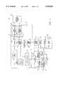
- FIG. 1is a patient base station block diagram showing the patient base station, physician's programming console and the monitor-defibrillator connected to either the patient base station or the electrode harness.
- FIG. 2is a block diagram showing the patient base station computer, real-time clock, counter timer, analog/digital converter and backup battery, and monitor-defibrillator battery connection.
- FIG. 3is a block diagram for the battery load test function.
- FIG. 4is a diagrammatic perspective view of the monitor-defibrillator and patient base station.
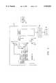
- FIG. 5is a block diagram for the patient base station patient interface module.
- FIG. 1An apparatus is provided for monitoring and supporting the monitor-defibrillator electronics and the rechargeable battery pack provided therein.
- the system 10 of the present inventionis shown schematically in FIG. 1.
- a monitor-defibrillator 12is included which is operatively connectable via an interface module 26, to either a patient base station 30 or an electrode harness 66 having two groups of electrodes 14, 16.
- a group of delivering electrodes 14is provided for delivering a cardioverting or defibrillating shock when necessary to a patient.
- Another group of electrodes 16performs sensing operations in which the physiological condition of a patient may be monitored.
- the delivering electrodes 14are operatively connected to a converter-defibrillator 19 located within the monitor-defibrillator 12.
- the electrode harness 66also includes a patient display 24 with the capability of displaying visual messages, enunciating audio messages and activating audio alarms.
- the patient display 24also includes various buttons for providing the patient with a means of input to the device.
- the operation of the electrode harness/monitor-defibrillatorare more particularly described in co-pending application Ser. No. 08/651,274, assigned to the present assignee and hereby incorporated by reference herein.
- the battery pack 18is responsible for providing the necessary power to operate the converter-defibrillator circuitry for delivering the cardioverting or defibrillating shock. Therefore, it is important that the energy capacity of battery 18 be ensured.
- the monitor-defibrillator 12preferably utilizes a high-energy-density nickel-cadmium battery. Preferably, the battery is comprised of five 1.2 volt cells connected in series to yield six volts.
- the monitor-defibrillator 12also includes battery control circuitry 20 which can activate the battery 18 to deliver its charge to the converter-defibrillator 19 and subsequently to the delivery electrodes 14 when necessary.
- the battery control circuitry 20is responsive to certain data conditions of the patient. For this reason, the battery control 20 is operatively connected to data storage/processor 22, also located within the monitor-defibrillator 12.
- the data storage/processor 22receives data from the sensing electrodes 16.
- the data storage/processor 22 in the monitor-defibrillatorpreferably utilizes non-volatile memory.
- the data storage/processor 22stores programmable system operational parameters, system operating status information, digitized ECG episodes and the results of hardware diagnostic tests. This data, through subsequent analysis, provides the means to allow reconstruction of ECG events and analysis of device performance.
- the monitor-defibrillator 12is able to perform various system and battery checks. Energy usage of the monitor-defibrillator 12 is monitored in real time to determine the useful energy remaining of the battery 18 per charge.
- the patient display 24 located on the electrode harness 66indicates the operating time remaining for the battery 18. The patient may access this function at any time by pressing a button on the patient display 24.
- the run-time parameteris available to an external host via the communications interface located in the interface module 26.
- a low battery condition as determined by the monitor-defibrillator 12is recorded in non-volatile memory of the data storage/processor 22. The patient is also alerted to a low battery condition by the patient display 24.
- the monitor-defibrillator 12monitors the battery current consumption and, if required, makes an appropriate adjustment to the battery run-time parameter based on sampling the real-time monitor-defibrillator current consumption.
- the currentis monitored by an analog circuit in the monitor-defibrillator 12 and is input into a comparator at a trip level of current.
- the voltageis monitored but is not sent to the comparator.
- the trip levelis a level of current that is based on a precalculated worst case (i.e., maximum) average current developed for the device. For the particular hardware used with the present invention, the amount of typical maximum run current (i.e., the trip level current) is 74 milliamperes.
- the comparatortrips and the analog to digital converter in the data storage/processor 22 is commanded to read the analog representation of the current that is being drawn by the monitor-defibrillator 12.
- the monitor-defibrillator 12measures the time period of excessive current draw and the amount of current above the trip level. Based on the measured readings, time is deducted from the battery runtime parameter by the monitor-defibrillator. The updated runtime remaining may be accessed by the patient at any time, as discussed above.
- the data storage/processor 22presumes that the actual current is the same as the trip current when deducting time from the battery runtime parameter.
- the typical maximum run currentis provided as 74 mils, the battery 18 is nearly always providing a current below 74 milliamps.
- the patienthas the capability to access buttons on the patient display 24 that when activated will cause the remaining run time to be indicated. If a patient is very active so as to cause one of the sensing electrodes 16 to have fallen off or otherwise become disconnected from the patient, an alarm is sounded. The activation of this alarm also utilizes energy which will be subtracted from the run time.
- the current measuring capability of the monitor-defibrillator 12does not include current drawn by the converter-defibrillator 19.
- the monitor-defibrillator 12tracks the periods when the converter-defibrillator 19 is actively drawing current from the battery 18 and makes adjustments to the battery run time to compensate for the energy loss.
- the monitor-defibrillator 12also makes adjustments for depletion of battery 18 capacity during periods when the device is not being used. When not in use (such as when stored on a shelf or taken by the patient on a day's outing as a spare device) the monitor-defibrillator 12 will automatically power itself up at specified intervals and make adjustments to the battery run time to compensate for energy losses due to self-discharge of the battery and current draw of monitor-defibrillator 12 components when powered down.
- the monitor-defibrillator 12will utilize measures intended to reduce depletion of battery 18 capacity in order to maximize available energy if a treatment pulse is required.
- the monitor-defibrillator 12will be optimized to execute its monitoring functions as rapidly as possible and then enter a low power operating mode until the monitoring functions must again be executed.
- the monitor-defibrillatorcan be kept in a low power operating mode when not performing necessary system operating functions. Additionally, when possible, high current devices will be powered down after completing their required tasks.
- An examplewould be the analog to digital converter. By scheduling analog to digital conversion readings at the beginning of monitoring functions, the analog to digital converter can be powered down sooner than if analog to digital readings are interspersed throughout the monitoring functions.
- the monitor-defibrillator 12can also determine the available device operating time (prior to recharging the battery), taking into account at least: (1) adjustments for abnormally high current draw of the device including adjustments for converter operation or operation of other high current draw devices as well as adjustments for excessive current draw from a defective component; (2) adjustments for normal current draw during an elapsed time period; (3) adjustments for device fault conditions such as failure of a battery load test or a problem with operation of the converter; and (4) adjustments for depletion of battery capacity during periods of non-use.
- the patient display 24 or alarmscan be used to notify the patient of the available device operating time.
- the monitor-defibrillator 12will also utilize an analog to digital converter located in the data storage/processor 22 to supervise the battery 18 voltage during operation of the converter-defibrillator 19.
- the converter-defibrillator 19may be operated in either a fast charge mode or a slow charge mode.
- the fast charge modeminimizes the time to charge the converter-defibrillator 19 but at a maximized current draw from the battery 18.
- the slow charge modeminimizes the capacitor charging current but with an increased time to charge the converter-defibrillator 19.
- the converter-defibrillator 19is normally operated in fast charge mode.
- the monitor-defibrillator 12will switch the converter-defibrillator 19 to a slow charge mode. This will permit the battery 18 voltage level to recover to a level at which the monitor-defibrillator 12 can again reliably operate the converter-defibrillator 19.
- Use of the slow charge modepermits the converter to be operated and a therapy pulse delivered to the patient when the battery 18 capacity is low.
- the monitor-defibrillator 12will deactivate the converter and evaluate the energy capability stored in the converter. If the energy stored in the converter is sufficient to deliver at least a minimal energy pulse, such as, for example, 30 joules, then the treatment cycle will continue with delivery of the available energy. If there is not enough energy stored in the converter to deliver a minimal energy pulse, then the converter will be discharged. In addition, notification will be given using the patient display 24 that the device is disabled and medical assistance should be provided to the patient.
- the monitor-defibrillator 12determines that the battery 18 capacity has fallen below a level at which the system performance data is in danger of being corrupted then the monitor-defibrillator 12 will remove operating power. The removal of operating power will reserve the remaining battery 18 capacity for maintenance of the data storage/processor 22. The integrity of the data storage is essential to evaluating the proper operation of the device. Since this low level of battery 18 capacity is inadequate for reliable operation of the monitor-defibrillator, the best possible use of the remaining battery 18 capacity is to preserve the operational history of the device stored in the data storage/processor 22. When this state has been reached, the monitor-defibrillator will refuse to power up until connected to the patient base station 30. If required, the patient base station 30 will provide additional energy to the monitor-defibrillator 12 to insure proper functioning during this power up sequence. The patient base station will then retrieve the operational history from the monitor-defibrillator 12 and recharge the battery 18.
- the analog to digital converter located in the data storage/processor 22is powered up each interim cycle to sample the analog inputs. This interim cycle is preferably every 5 milliseconds, which generally corresponds to the ECG sampling rate. After sampling the analog inputs, the analog to digital converter is powered down to conserve battery power. There are entire portions of the monitor-defibrillator 12 that periodically go into a low current sleep mode.
- the patientis required to couple the monitor-defibrillator 12 with the patient base station 30 (see FIG. 4).
- the monitor-defibrillator 12is removed from the electrode harness 66 and inserted in the receptacle 31 of the patient base station, connection is made between the monitor-defibrillator interface 26 and a monitor-defibrillator interface 32 located within the patient base station 30.
- the patient base station monitor-defibrillator interface 32is thus operatively connected to the data storage/processor 22 of the monitor-defibrillator 12.
- the monitor-defibrillator interface 32can download information from the memory of the data storage/processor circuitry 22; i.e., information, that was received from both the sensing electrodes 16 regarding the patient's physiological data, and also from the battery control circuitry 20 regarding the operating history of the monitor-defibrillator 12.
- the monitor-defibrillator interface 32 of the patient base station 30is also operatively connected to the battery 18. In this way, the patient base station 30 can perform comprehensive tests as to the operating parameters of the battery 18. Further, charging of the battery 18 can also be performed through the monitor-defibrillator interface 32.
- the battery 18 of each monitor-defibrillator 12requires periodic charging. Thus, monitor-defibrillators 12 that are not in use are to be stored on a patient base station charging port (i.e., coupled to the monitor-defibrillator interface 32), where they undergo charging and maintenance operations.
- the patient base station 30provides battery status information to the patient by way of a visual display including indicator lights as well as by audio alarms provided by the patient interface 46.
- the power required to charge the battery 18 of the monitor-defibrillator 12is supplied by either an internal or an external power supply.
- an internal power supply 38may be used which is operatively connected to the charger interface module 34.
- a switch mode type power supply 38is preferred.
- a linear type power supply 38could also be utilized. If a linear type power supply 38 is used, a heat sink and a fan would be needed in the patient base station 30. Use of a switch mode type power supply 38 would eliminate the fan, reduce the size of the heat sinks and would reduce the size of the system package and is thus preferred.
- the power supply 38utilizes a power entry module 36.
- the power entry module 36provides a standard IEC 320 type power entry connector.
- the power entry module 36functions over a full range of standard household international voltages and frequencies.
- the power entry module 36shall preferably use a standard international "1/0" icon for power status indication.
- the monitor-defibrillator interface 32is operatively connected to the charger interface module 34 within the patient base station 30.
- the charger interface module 34provides a standard PC-AT compatible ISA type interface and provides all the necessary bus signals for computer control of the various charger interface module functions.
- data received by the monitor-defibrillator interface 32 from the data storage/processor 22 of the monitor-defibrillator 12is provided to a computer 40.
- communicationis then established for transfer of operational data to the patient base station mass data storage area 42. This data is a record of device performance and any ECG data that may have been stored within the monitor-defibrillator 12 during patient monitoring.
- the patient base stationinitiates data retrieval operations from the monitor-defibrillator 12 if operational or ECG data is stored within the internal memory included in the data storage/processor 22 of the monitor-defibrillator 12. As part of normal maintenance of the monitor-defibrillator 12, this data is transferred to the patient base station 30 for long-term data storage 42.
- the patient base station 30may store retrieved data on a removable floppy disk, removable or fixed hard disk or other removable media. In the preferred embodiment, the data is stored on a fixed hard disk.
- the computer 40 of the patient base station 30issues a clear memory command via the monitor-defibrillator interface 32 to the monitor-defibrillator 12. This command erases the temporary memory in the data storage/processor 22 in the monitor-defibrillator 12. In the embodiment utilizing rotating media, the patient base station notifies the patient when the removable media requires replacement due to inadequate storage area remaining.
- the computer 40 utilized by the patient base station 30incorporates an imbedded, PC-AT-compatible computer architecture.
- the computer 40preferably utilizes an IntelTM80 ⁇ 86 type central processing unit, with a performance no less than that of a 25 MHz 80386SX IntelTM processor.
- the computer 40preferably includes two standard PC-AT type serial ports.
- a modem interface port 44should also be available for connecting the computer 40 to a telephone modem (not shown).
- the modem interface 44is designed to interface to a telephone modem with no less than 14.4 kpbs data rate capability.
- the modempreferably interfaces to the single board computer 40 via one of its serial ports.
- a physician's programming console (“PPC”) interface 48provides a communication link from the patient base station (“PBS”) 30 to a physician's programming console 70.
- the physician's programming console interface 48contains an ethernet communications module 52 for providing a standard 10 Mbps data link to the physician's programming console 70. This module 52 preferably interfaces to the single board computer 40 via an expansion bus 54. Data transfers between the patient base station 30 and the physician's programming console 70 are handled via the ethernet port 52. This allows the significant amount of data generated by the monitor-defibrillator 12 to be offloaded in a reasonable time at the physician's office during thc patient's periodic visits.
- the external panel connection for the high speed physician's programming console 70 data linkcan use a standard BNC type female connector.
- a serial communications port 50is also part of the physician programming console interface 48 and is provided for connection of the computer 40 to the physician's programming console 70. Data transfer from the patient base station 30 to the physician's programming console 70 can also occur via high speed modem interface 44 from the patient's home.
- the computer 40is operatively connected to an ISA type expansion bus 54.
- the expansion bus 54is designed to be capable of supporting up to four 16 bit expansion modules or cards.
- the computer 40utilizes the expansion bus 54 to facilitate communications, control and status transfers to and from the charger interface module 34 and ethernet communication module 52 of the physicians programming console interface 48.
- the expansion bus 54also provides power to the computer 40 and the ethernet communication module 52 from the charger interface module 34.
- the operating system and applications software for the patient base station 30may be stored on rotating media in the mass data storage area 42.
- the preferred embodimentembeds this software in non-volatile read only memory, such as EEPROM or FLASH memory. These embodiments allow the device to operate without need of rotating media.
- Additional non-volatile memoryis provided to store certain manufacturing information and device-specific data. These memory locations are written to only during the initial manufacturing processes and are then write inhibited by hardware means.
- a real time clockmay be implemented in conjunction with the computer 40 to maintain date and time of day information.
- the clockhas backup power 62 provided to maintain operation if power is removed from the patient base station.
- a counter-timer 72is provided to coordinate time critical operations.
- An analog to digital converter 64is also provided.
- the patient base station computer 40controls battery charging, both rapid charging and float charging once the full charge point is reached.
- the computer 40also controls discharging of the battery 18, as required.
- a battery capacity testis periodically performed to verify the stored energy capacity of the monitor-defibrillator battery pack 18.
- the system processor 40controls all battery capacity measurement operations by discharging the battery 18 to a defined starting level, rapid-charging the battery 18 to full potential, implementing a timed discharge cycle to deplete the battery 18 and calculating the actual energy capacity. This process can determine if a bad cell is present in the battery pack, or the measured battery capacity is less than a defined acceptable limit.
- the patient interface module 46can have a visual display 47, battery status LED indicators 51, acknowledge push button 57 and ambient light sensor 49.
- the patient interface module 46can be operatively associated with the charger interface module 34 and the analog to digital converter 64.
- the analog to digital converter 64 with an analog multiplexeris preferably provided within the patient base station 30.
- This analog to digital converter 64allows the single board computer 40 (FIG. 1) to monitor the charging current of the charger/discharger 34, discharging current of the charger/discharger 34, the battery voltage present at the monitor-defibrillator interface 32, the ambient light sensor 49 of the patient interface module 46 and the ambient temperature within the patient base station 30 enclosure via a temperature sensor 55 (shown in FIG. 2).
- the patient interface 46 in the patient base station 30indicates the status of the monitor-defibrillator battery 18 during the battery capacity test cycle.
- the patient interface 46preferably incorporates a front panel mounted vacuum fluorescent (VF) type display 47 (shown in FIG. 4).
- This display 47may be a character type with standard 5 mm, 5 ⁇ 7 dot characters.
- the PBS display 47is preferably arranged in one of the following configurations: a 2 line by 40 character or a 4 line by 20 character.
- the PBS display 47is controlled by the single board computer 40 via the charger interface module 34 through a parallel data interface.
- a graphics type LCDmay be used for the PBS display 47. If an LCD display is used, the patient base station may include an ambient light sensor 49 to control the LCD backlight for improved readability.
- the patient base station 30tracks battery 18 usage and notifies the patient when replacement of the battery 18 is required. If the battery 18 expiration parameters have been exceeded (the expiration date or the number of charge cycles), the battery 18 can still be used by the monitor-defibrillator 12, but the patient will be notified to replace the monitor-defibrillator 12 as soon as possible.
- the number of charging cycles performed on the battery 18is recorded in the monitor-defibrillator memory of the data storage/processor 22. Also, the date the battery 18 was installed in the monitor-defibrillator 12, the type of cell used in the battery 18, and the expiration date of the battery 18 as well as any other pertinent information is stored in monitor-defibrillator data storage/processor 22.
- the communications interface created when the patient base station 30 and attached monitor-defibrillator 12 is connected to the physician's programming console 70is utilized during the initial configuration programming of the monitor-defibrillator 12.
- the following informationis configured: name, address, telephone number, hospital, attending physician, medications; monitor-defibrillator detection and treatment parameters such as heart rate threshold or rate cutoff, defibrillation energy to be delivered in therapy pulses; and monitor-defibrillator manufacturing data such as device serial numbers, monitor-defibrillator battery pack and expiration date, electrode harness(s) and expiration date(s).
- a data communications protocolfacilitates the transfer of digital information between the patient base station 30 and the physician's programming console 70. This protocol consists of transferring data in blocks or frames. To ensure the integrity of transmitted and received data, the protocol implements error checking techniques.
- the patient base station 30 to physician's programming console 70 communications protocolconsists of transferring data in frames. Communication frames are transferred via the serial communication port 50. Serial communication port 50 hardware control lines are utilized to provide handshaking between the patient base station 30 and the physician's programming console 70 that will delimit the frame boundaries.
- Each communication cycleconsists of a command frame sent from the physician's programming console 70 to the patient base station 30, followed by a response frame sent from the patient base station 30 to the physician's programming console 70.
- Each command framewill contain a command code followed by any relevant data, followed by an error checking code such as a CRC code.
- the patient base station 30will return a response frame that contains an ACK code, followed by the original received command code, followed by any relevant data, followed by an error checking code such as a CRC code.
- the patient base station 30will return a response frame that contains a NAK code, followed by the original received command code, followed by any relevant data, followed by an error checking code such as a CRC code.
- the patient base station 30will ignore the communication frame.
- the physician's programming console 70will be responsible for monitoring the patient base station 30 response. If the patient base station 30 does not respond to a command frame the physician's programming console 70 can elect to resend the frame.
- the physician's programming console 70can elect to resend the frame.
- Another data communications protocolfacilitates the transfer of digital information between the monitor-defibrillator 12 and the patient base station 30.
- the protocolconsists of transferring data in blocks or frames.
- the patient base station (“PBS”) 30 to monitor-defibrillator (“M-D”) 12 communications protocolconsists of transferring data in frames. Communication frames are transferred via the PBS/M-D interface 32. PBS/M-D interface 32 hardware control lines are utilizcd to provide handshaking between the patient base station 30 and the monitor-defibrillator 12 that will delimit communication frame boundaries.
- Each communication cycleconsists of a command frame sent from the patient base station 30 to the monitor-defibrillator 12, followed by a response frame sent from the monitor-defibrillator 12 to the patient base station 30.
- Each command framewill contain a command code followed by any relevant data, followed by an error checking code such as a CRC code.
- the monitor-defibrillator 12will return a response frame that contains an ACK code, followed by the original received command code, followed by any relevant data, followed by an error checking code such as a CRC code.
- the monitor-defibrillator 12will return a response frame that contains a NAK code, followed by the original received command code, followed by any relevant data, followed by an error checking code such as a CRC code.
- the patient base station 30will determine and execute a response appropriate for the failed monitor-defibrillator 12 command process.
- the monitor-defibrillator 12If a command frame is received by the monitor-defibrillator 12 that contains an invalid error checking code, the monitor-defibrillator 12 will return a response frame that contains a code indicating that the command was not properly received and should be resent.
- the patient base station 30can elect to resend the command frame.
- the patient base station 30can elect to resend the frame or initiate monitor-defibrillator 12 fault condition processing.
- the patient base station 30offers a collection of commands that the physician's programming console 70 can utilize during communications with the patient base station 30.
- the command setprovides a means to initiate various patient base station 30 and monitor-defibrillator 12 diagnostic, configuration, and data retrieval procedures.
- the physician's programming console 70can gain access to various monitor-defibrillator 12 information and operational features by issuing commands to the patient base station 30 via the serial communications port 50. Upon receipt of these commands, the patient base station 30 will issue the appropriate commands to the monitor-defibrillator 12 via the PBS/M-D interface 32, that will carry out the desired operation. The patient base station 30 will return to the physician's programming console 70 the monitor-defibrillator 12 response to the operation.
- a digital output from the monitor-defibrillator data storage/processoris provided to control the activation of the battery test load. Activation of the load places a high current demand on the monitor-defibrillator battery 18. This determines if the monitor-defibrillator battery pack contains any defective cells.
- the monitor-defibrillator 12can determine the available device operation time (prior to recharging the battery) utilizing adjustments for abnormally high current draw, normal current draw, device fault conditions, and depletion of battery capacity during periods when the device is not in use.
- the monitor-defibrillator 12Upon command from the patient base station or the monitor-defibrillator display, the monitor-defibrillator 12 performs a battery load test. The monitor-defibrillator 12 returns a pass-fail indication to the patient base station or the display. Load tests are most often performed with the display as the host. If the battery 18 fails the load test, the battery voltage measurement prior to the load test and at the point of failure are stored in the monitor-defibrillator non-volatile memory.
- the patient base station 30provides circuitry in the charger interface module 34, that can charge or discharge the monitor-defibrillator 12 battery pack 18.
- the charger interface module 34connects to the monitor-defibrillator 12 battery pack 18 via the PBS/M-D interface 32.
- the patient base station 30Prior to battery pack 18 maintenance operations, the patient base station 30 will retrieve battery pack 18 identification information from the monitor-defibrillator 12 via the PBS/M-D interface 32.
- Two charging modesare provided; rapid charging and float charging.
- the charger interface module 34supplies charging current at the one hour charge rate of the battery pack 18.
- the charger interface module 34supplies charging current at the continuous maintenance rate of the battery pack 18.
- the rapid and float charge current rates supplied by the charger interface module 34arc adjustable by the patient base station computer 40.
- the patient base station computer 40will configure the charger interface module 34 to supply a charge current rate that is appropriate for the connected battery pack 18.
- the battery charger interface module 34can be controlled by the patient base station computer 40 or by the monitor-defibrillator 12 via the PBS/M-D interface 32.
- Monitor-defibrillator 12 control of the charger interface module 34is accomplished by activating I/O control lines located in the PBS/M-D interface 32. These I/O lines will configure the charger interface module 34 for the desired charge/discharge operation.
- the patient base station computer 40can control the I/O lines and configure the charger interface module 34 for the desired charge/discharge operation.
- the monitor-defibrillator 12controls the configuration of the charger interface module 34.
- the patient base station 30 configuration of the charger interface module 34is a redundant feature that can be utilized if certain monitor-defibrillator 12 fault conditions exist such as a totally discharged monitor-defibrillator 12 battery pack 18.
- Battery pack 18 charge and discharge cyclesare initiated by the patient base station computer 40.
- the patient base station 30retrieves monitor-defibrillator 12 battery operational status data from the data storage/processor 22 via PBS/M-D interface 32.
- the retrieved battery operational status dataincludes information such as the remaining battery capacity, fault condition flags, expiration parameters, battery maintenance parameters, and battery identification information.
- the patient base station 30analyzes the retrieved battery data to determine the appropriate battery pack 18 maintenance procedure.
- a command to initiate a rapid charge cyclewill be sent to the monitor-defibrillator 12 via the PBS/M-D interface 32.
- the monitor-defibrillator 12Upon receipt of this command, the monitor-defibrillator 12 will configure the charger interface module 34 for rapid charge operation by activating I/O control lines located in the PBS/M-D interface 32.
- the monitor-defibrillator 12will monitor the rapid charge sequence for completion and fault conditions. Successful rapid charge completion is determined by the monitor-defibrillator 12 monitoring the voltage level at the battery pack 18 positive terminal via the A/D converter located in the data storage/processor module 22.
- Successful rapid charge completioncan also be declared if the monitor-defibrillator 12 detects a defined change in battery pack 18 temperature.
- the monitor-defibrillator 12monitors the battery temperature via a temperature sensor located in the battery pack 18 and the A/D converter located in the data storage/processor module 22.
- the monitor-defibrillator 12will configure the charger interface module 34 for float charge operation by activating I/O control lines located in the PBS/M-D interface 32, reset the monitor-defibrillator 12 runtime parameter to the maximum value, and issue a rapid charge complete communications frame to the patient base station 30 via the PBS/M-D interface 32.
- the rapid charge cyclewill be aborted if the monitor-defibrillator 12 detects one of the following conditions: a battery pack 18 over voltage condition; a battery pack 18 over temperature condition; or a defined time interval elapsed without a rapid charge completion detected.
- the limit valuesare manufacturing parameters that are stored in the monitor-defibrillator 12 data storage/processor module 22.
- the monitor-defibrillator 12will configure the charger interface module 34 for float charge operation by activating I/O control lines located in the PBS/M-D interface 32; the monitor-defibrillator 12 will set it's runtime parameter to zero, which will cause patient warning messages on the display 24; and the monitor-defibrillator 12 will issue a rapid charge fault communications frame to the patient base station 30 via the PBS/M-D interface 32.
- the patient base station 30receives a rapid charge fault communications frame from the monitor-defibrillator 12, the following operations will be performed: the event will be logged in the patient base station 30 operations log file located in the data storage module 42; and the patient base station 30 will activate a patient warning message that indicates the monitor-defibrillator 12 should be serviced.
- the patient base station 30will insure proper charge operation by monitoring various system parameters.
- the system parameter limit valuesare stored in the data storage module 42 during the patient base station 30 manufacturing process.
- the charging current supplied to the battery pack 18is monitored for proper levels via an A/D converter 64 (FIG. 5) channel connected to the charger interface module 34. If the measured current is outside the defined limits, the patient base station 30 will abort the rapid charge cycle.
- A/D converter 64FIG. 5
- the charging voltage on the battery pack 18is monitored for proper levels via an A/D converter 64 channel connected to the charger interface module 34. If the measured voltage is outside the defined limits, the patient base station 30 will abort the rapid charge cycle.
- the patient base station 30will abort the rapid charge cycle if the counter timer 72 (FIG. 2) indicates the charge cycle exceeded the maximum charge completion interval.
- an abort rapid charge cycle commandwill be issued to the monitor-defibrillator 12 via the PBS/M-D interface 32; the patient base station 30 will configure the charger interface module 34 for float charge operation; the patient base station 30 will issue a command to the monitor-defibrillator 12 to set the runtime parameter to zero, which will cause patient warning messages on the display 24; the event will be logged in the patient base station 30 operations log file located in the data storage module 42; and the patient base station 30 will activate a patient warning message that indicates the monitor-defibrillator 12 should be serviced.
- the patient base station 30may initiate a discharge cycle of the monitor-defibrillator 12 battery pack 18.
- the discharge cycleis utilized both during the battery capacity test as well as during the process of reconditioning the battery energy storage capabilities.
- a command to initiate a discharge cyclewill be sent to the monitor-defibrillator 12 via the PBS/M-D interface 32.
- the monitor-defibrillator 12Upon receipt of this command the monitor-defibrillator 12 will set the monitor-defibrillator 12 runtime parameter to zero and configure the charger interface module 34 for discharge operation by activating I/O control lines located in the PBS/M-D interface 32.
- the monitor-defibrillator 12will monitor the discharge sequence for completion and fault conditions. Successful discharge completion is determined by the monitor-defibrillator 12 detecting the defined final discharge voltage threshold on the battery pack 18 positive terminal via the A/D converter located in the data storage/processor module 22.
- the monitor-defibrillator 12When the monitor-defibrillator 12 detects a successful discharge completion, the monitor-defibrillator 12 will configure the charger interface module 34 for float charge operation, by activating I/O control lines located in the PBS/M-D interface 32, and issue a discharge complete communications frame to the patient base station 30 via the PBS/M-D interface 32.
- the discharge cyclewill be aborted if the monitor-defibrillator 12 detects one of the following conditions: a battery pack 18 over temperature condition; or a defined time interval has elapsed without the detection of the discharge complete condition.
- the limit valuesare manufacturing parameters that are stored in the monitor-defibrillator 12 data storage/processor module 22.
- the monitor-defibrillator 12will configure the charger interface module 34 for float charge operation by activating I/O control lines located in the PBS/M-D interface 32; and the monitor-defibrillator 12 will issue a discharge fault communications frame to the patient base station 30 via the PBS/M-D interface 32. If the patient base station 30 receives a discharge fault communications frame from the monitor-defibrillator 12, the event will be logged in the patient base station 30 operations log file located in the data storage module 42 and a patient warning message will be activated on the PBS display 47 that indicates the monitor-defibrillator 12 should be serviced.
- the patient base station 30will insure proper discharge operation by monitoring various system parameters.
- the system parameter valuesare stored in the data storage module 42 during the patient base station 30 manufacturing process.
- the discharge current drawn from the battery pack 18is monitored for proper levels via an A/D converter 64 channel connected to the charger interface module 34. If the measured current is outside the defined limits, the patient base station 30 will abort the discharge cycle.
- the discharge voltage on the battery pack 18is monitored for proper levels via an A/D converter 64 channel connected to the charger interface module 34. If the measured voltage is outside the defined limits, the patient base station 30 will abort the discharge cycle.
- the patient base station 30will abort the discharge cycle if the counter timer 72 indicates the discharge cycle exceeded the maximum discharge completion interval.
- an abort discharge cycle commandwill be issued to the monitor-defibrillator 12 via the PBS/M-D interface 32; the patient base station 30 will configure the charger interface module 34 for float charge operation; the patient base station 30 will issue a command to the monitor-defibrillator 12 to set the runtime parameter to zero, which will cause patient warning messages on the display 24; the event will be logged in the patient base station 30 operations log file located in the data storage module 42; and the patient base station 30 will activate a patient warning message that indicates the monitor-defibrillator 12 should be serviced.
- the rapid charge cycle or discharge cyclewill not be initiated if the monitor-defibrillator 12 determines that the battery pack 18 temperature is outside a set of defined limits.
- the limit valuesare manufacturing parameters that are stored in the monitor-defibrillator 12 data storage/processor module 22.
- monitor-defibrillator 12If the monitor-defibrillator 12 is removed from the patient base station 30 prior to completion of all battery pack maintenance operations, a message and alarm will be activated on the patient interface module 46. The message will indicate the monitor-defibrillator maintenance is not complete and to return the monitor-defibrillator to the patient base station. The interrupted maintenance procedure will be continued if the removed monitor-defibrillator 12 is reconnected to the patient base station 30.
- the energy delivery capabilities of the battery pack 18are periodically verified by testing the battery 18 energy capacity and high current delivery capabilities.
- the patient base station 30will perform an energy capacity test on the battery pack 18 if the elapsed time from the last capacity test, as indicated by data retrieved from monitor-defibrillator data storage/processor module 22 via the PBS/M-D interface 32, exceeds the maximum time interval parameter stored in the data storage module 42, or status data retrieved from monitor-defibrillator data storage/processor module 22 via the PBS/M-D interface 32, indicates that the battery 18 operational performance was deficient during the previous patient monitoring cycle.
- the battery 18 energy capacity test procedureconsists of the following operations: the patient base station 30 will activate a message on the patient interface 46 visual display 47 that indicates the monitor-defibrillator 12 is being tested and to wait for the test to complete; the patient base station 30 initiates a battery discharge cycle to condition the battery for a full charge cycle; initiate a rapid charge cycle when the discharge cycle is complete to charge the battery 18 to full capacity; the patient base station 30 initiates a second discharge cycle when the rapid charge cycle is complete; and the patient base station 30 initiates a final rapid charge cycle at the completion of the second discharge cycle to ready the battery 18 for service.
- the duration of the second discharge cycleis timed by a counter timer located in the monitor-defibrillator 12 data storage/processor module 22.
- monitor-defibrillator 12will compare the measured battery 18 discharge time with an acceptance parameter stored in storage/processor module 22. If the capacity discharge time is within the acceptable limit, monitor-defibrillator 12 will issue a capacity discharge pass communications frame to the patient base station 30 via the PBS/M-D interface 32.
- the monitor-defibrillator 12will set a battery capacity fault status flag located in the data storage/processor module 22, and issue a capacity discharge fault communications frame to the patient base station 30 via the PBS/M-D interface 32.
- the patient base station 30will log the event in a log file located in the data storage module 42. Whenever the patient base station 30 receives a capacity discharge fault indication from the monitor-defibrillator 12, a patient warning message will be activated which indicates that the monitor-defibrillator 12 should be serviced as soon as possible.
- the patient base station 30Each time a monitor-defibrillator 12 is connected to the patient base station 30, the patient base station 30 will retrieve the monitor-defibrillator 12 battery capacity fault status flag located in the data storage/processor module 22. If the battery capacity fault status flag is active, the patient base station 30 will initiate normal battery maintenance operations, with the exception of the battery capacity test which will no longer be performed. The patient base station 30 will also issue a command to the monitor-defibrillator 12 to set the runtime parameter to zero. This will cause repeated patient warning messages on the patient display 24.
- the patientwill be notified by the patient base station 30 that the monitor-defibrillator 12 should be serviced.
- the notification sequencewill be activated until the patient acknowledges receipt by pressing a button 57 (FIG. 4) on the patient interface 46, or the monitor-defibrillator 12 is removed from the patient base station 30. Normal battery maintenance will continue so that the patient may use the monitor-defibrillator 12.
- the patient base station 30When a rapid charge cycle or battery discharge cycle is initiated, the patient base station 30 will deactivate the particular one of the battery status LED indicators 51 which is the "READY” LED indicator on the patient interface module 46 and activate the particular one of the battery status LED indicators 51 which is the "CHARGING" LED indicator. During the rapid charge cycle, the patient base station 30 displays a message on the patient interface visual display 47 that the monitor-defibrillator battery 18 is being charged and the monitor-defibrillator 12 is not ready for use.
- the patient base stationperforms the following:
- a messageis displayed on the PBS display 47 indicating that the monitor-defibrillator 12 is ready for use; the PBS 30 "READY” LED 51 is activated; the "CHARGING” LED 51 is deactivated; and the monitor-defibrillator 12 is powered down.
- the patient base station 30logs the following battery maintenance information into a maintenance log: the start and completion times of battery operations; the length of the charge/discharge cycles; any abnormal conditions; and the charge cycle count, and if enabled, the battery voltage measurements taken during charge and discharge cycles.
- the maintenance logis stored in the data storage module 42.
- the patient base station 30issues various diagnostic test commands to the monitor-defibrillator 12. These tests are performed on a regular basis. Some tests are performed each time the monitor-defibrillator 12 is connected to the patient base station 30. Others are performed only as required.
- the monitor-defibrillator 12executes the received commands and reports the test results to the patient base station 30.
- the patient base station 30maintains a log of the test results on the mass storage media 42. If a fault is detected during any diagnostic procedure, the patient is notified of the condition along with the appropriate corrective action.
- the preferred patient base station systemutilizes a charger interface module board. Stacked on top of that board are purchased assemblies of PC104 boards which form the CPU module 40 and Ethernet module 52. These boards are ISA compatible because the expansion bus 54 is an ISA type bus. The stacks of PC104 boards require a great deal of cabling which is very costly. Thus, all of the major system functions could be implemented on a single PC board. This would eliminate much of the cabling.
Landscapes
- Health & Medical Sciences (AREA)
- Engineering & Computer Science (AREA)
- General Health & Medical Sciences (AREA)
- Public Health (AREA)
- Heart & Thoracic Surgery (AREA)
- Biomedical Technology (AREA)
- Nuclear Medicine, Radiotherapy & Molecular Imaging (AREA)
- Radiology & Medical Imaging (AREA)
- Life Sciences & Earth Sciences (AREA)
- Animal Behavior & Ethology (AREA)
- General Physics & Mathematics (AREA)
- Cardiology (AREA)
- Veterinary Medicine (AREA)
- Physics & Mathematics (AREA)
- Power Engineering (AREA)
- Manufacturing & Machinery (AREA)
- Chemical & Material Sciences (AREA)
- Chemical Kinetics & Catalysis (AREA)
- Electrochemistry (AREA)
- General Chemical & Material Sciences (AREA)
- Electrotherapy Devices (AREA)
Abstract
Description
Claims (30)
Priority Applications (5)
| Application Number | Priority Date | Filing Date | Title |
|---|---|---|---|
| US08/995,713US5929601A (en) | 1997-12-22 | 1997-12-22 | Battery management apparatus for portable electronic devices |
| CA002240996ACA2240996A1 (en) | 1997-12-22 | 1998-06-18 | Battery management apparatus for portable electronic devices |
| DE69820015TDE69820015T2 (en) | 1997-12-22 | 1998-06-30 | Battery maintenance apparatus for portable electronic equipment |
| EP98112054AEP0923961B1 (en) | 1997-12-22 | 1998-06-30 | Battery management apparatus for portable electronic devices |
| US09/361,110US6169387B1 (en) | 1997-12-22 | 1999-07-26 | Battery management apparatus for portable electronic devices |
Applications Claiming Priority (1)
| Application Number | Priority Date | Filing Date | Title |
|---|---|---|---|
| US08/995,713US5929601A (en) | 1997-12-22 | 1997-12-22 | Battery management apparatus for portable electronic devices |
Related Child Applications (1)
| Application Number | Title | Priority Date | Filing Date |
|---|---|---|---|
| US09/361,110Continuation-In-PartUS6169387B1 (en) | 1997-12-22 | 1999-07-26 | Battery management apparatus for portable electronic devices |
Publications (1)
| Publication Number | Publication Date |
|---|---|
| US5929601Atrue US5929601A (en) | 1999-07-27 |
Family
ID=25542126
Family Applications (1)
| Application Number | Title | Priority Date | Filing Date |
|---|---|---|---|
| US08/995,713Expired - LifetimeUS5929601A (en) | 1997-12-22 | 1997-12-22 | Battery management apparatus for portable electronic devices |
Country Status (4)
| Country | Link |
|---|---|
| US (1) | US5929601A (en) |
| EP (1) | EP0923961B1 (en) |
| CA (1) | CA2240996A1 (en) |
| DE (1) | DE69820015T2 (en) |
Cited By (107)
| Publication number | Priority date | Publication date | Assignee | Title |
|---|---|---|---|---|
| US6067030A (en)* | 1998-03-13 | 2000-05-23 | At&T Corp. | Method and apparatus for providing network infrastructure information for a network control center |
| US6166522A (en)* | 1999-06-08 | 2000-12-26 | Motorola, Inc. | Battery conditioning scheme |
| US6169387B1 (en)* | 1997-12-22 | 2001-01-02 | Lifecor, Inc. | Battery management apparatus for portable electronic devices |
| US6301502B1 (en) | 1997-03-07 | 2001-10-09 | Cardiac Science Inc. | Defibrillation system |
| US6329822B1 (en) | 2000-02-11 | 2001-12-11 | Daniel J. Powers | Periodic automatic self-test system and methodology |
| US6456036B1 (en)* | 2000-09-29 | 2002-09-24 | Motorola Inc. | Battery having a network communication interface |
| US6456042B1 (en)* | 2000-11-27 | 2002-09-24 | Delphi Technologies, Inc. | Method and apparatus for charging batteries at reduced overcharge levels |
| US6459173B1 (en) | 2000-10-30 | 2002-10-01 | Rockwell Automation Technologies, Inc. | Self-programmable battery load/bias for memory expansion module |
| US20030117442A1 (en)* | 2001-12-26 | 2003-06-26 | Yuemean Chen | Dynamic indication for capacitor charging status |
| US20030176897A1 (en)* | 2001-04-10 | 2003-09-18 | Cardiac Pacemakers, Inc. | System and method for measuring battery current |
| US20040002836A1 (en)* | 2002-06-27 | 2004-01-01 | Kurt Raichle | Apparatus and method for testing and charging a power source with ethernet |
| US20040046026A1 (en)* | 2002-09-06 | 2004-03-11 | Scott Krampitz | Code reading apparatus and method |
| US6721685B2 (en)* | 2000-08-23 | 2004-04-13 | Hitachi, Ltd. | Remote maintenance system |
| US20040189444A1 (en)* | 2003-03-31 | 2004-09-30 | Gill Andrew M. | Maintenance interval timer and method of monitoring maintence intervals |
| US20040268004A1 (en)* | 2003-06-27 | 2004-12-30 | Oakley Nicholas W | Always-on removable communicator display |
| US20050007073A1 (en)* | 2003-07-11 | 2005-01-13 | James Kristofer J. | Indicator of remaining energy in storage cell of implantable medical device |
| US20050088145A1 (en)* | 2003-10-23 | 2005-04-28 | Robert Loch | Battery charge indicator such as for an implantable medical device |
| US20050233205A1 (en)* | 2004-04-19 | 2005-10-20 | Fujitsu Limited | Diagnosis method, power supply control device, electronic apparatus, battery pack and computer-readable storage medium |
| US20050277994A1 (en)* | 2004-06-09 | 2005-12-15 | Mcnamee Paul | Apparatus and method for estimating battery condition in implantable cardiac devices |
| US20060001550A1 (en)* | 1998-10-08 | 2006-01-05 | Mann Alfred E | Telemetered characteristic monitor system and method of using the same |
| US7024321B1 (en)* | 2000-07-20 | 2006-04-04 | Qualcomm, Incorporated | Battery monitoring system with low power and end-of-life messaging and shutdown |
| US20060149156A1 (en)* | 2004-12-13 | 2006-07-06 | Cardiocore Lab, Inc. | Method and apparatus for transfer of captured electrocardiogram data |
| US7079019B1 (en)* | 2004-08-02 | 2006-07-18 | Kenneth Ruggiero | Registration and inspection alarm apparatus |
| US20060161068A1 (en)* | 2002-04-16 | 2006-07-20 | Hastings Mark J | Venturi ECG electrode system |
| US20060259080A1 (en)* | 2005-03-21 | 2006-11-16 | Defibtech, Llc | System and method for presenting defibrillator status information while in standby mode |
| US20070035274A1 (en)* | 1999-04-15 | 2007-02-15 | Daniele Brotto | Method and apparatus for obtaining product use information |
| US7194308B2 (en) | 2003-11-12 | 2007-03-20 | Cardiac Pacemakers, Inc. | System and method for monitoring or reporting battery status of implantable medical device |
| US20070164704A1 (en)* | 2006-01-13 | 2007-07-19 | Horizon Technologies, Inc. | Plug with supplemental memory |
| US20070273714A1 (en)* | 2006-05-23 | 2007-11-29 | Apple Computer, Inc. | Portable media device with power-managed display |
| US20080033495A1 (en)* | 2006-08-01 | 2008-02-07 | Kumar Uday N | External Defibrillator |
| US20080082146A1 (en)* | 2006-09-29 | 2008-04-03 | Cardiac Pacemakers, Inc | Temperature compensation for analog circuits in implantable medical device |
| US20080136652A1 (en)* | 2006-03-21 | 2008-06-12 | Defibtech, Llc | System and Method for Effectively Indicating Element Failure or a Preventive Maintenance Condition in an Automatic External Defibrillator (AED) |
| US20080250166A1 (en)* | 2002-09-11 | 2008-10-09 | Physio-Control, Inc. | Medical Device Status Information System |
| US20080306560A1 (en)* | 2007-06-06 | 2008-12-11 | Macho John D | Wearable defibrillator with audio input/output |
| US20080312709A1 (en)* | 2007-06-13 | 2008-12-18 | Volpe Shane S | Wearable medical treatment device with motion/position detection |
| US7548781B2 (en) | 2005-03-21 | 2009-06-16 | Defibtech, Llc | Environmentally responsive active status indicator system and method |
| US20090187225A1 (en)* | 2005-03-21 | 2009-07-23 | Defibtech, Llc | PCB blade connector system and method |
| US20100153039A1 (en)* | 2002-06-27 | 2010-06-17 | Kurt Raichle | Apparatus and Method for Testing a Power Source |
| US20100228137A1 (en)* | 2009-03-07 | 2010-09-09 | Shenzhen Futaihong Precision Industry Co., Ltd. | Heart rate alarm system and method |
| US20100298899A1 (en)* | 2007-06-13 | 2010-11-25 | Donnelly Edward J | Wearable medical treatment device |
| US8044795B2 (en)* | 2007-02-28 | 2011-10-25 | Apple Inc. | Event recorder for portable media device |
| US20120123491A1 (en)* | 2010-11-15 | 2012-05-17 | William Tom Hunter | Defibrillator device with status indicating transport handle |
| US8406842B2 (en) | 2010-12-09 | 2013-03-26 | Zoll Medical Corporation | Electrode with redundant impedance reduction |
| US8600486B2 (en) | 2011-03-25 | 2013-12-03 | Zoll Medical Corporation | Method of detecting signal clipping in a wearable ambulatory medical device |
| US8644925B2 (en) | 2011-09-01 | 2014-02-04 | Zoll Medical Corporation | Wearable monitoring and treatment device |
| US20140040649A1 (en)* | 2012-08-01 | 2014-02-06 | Pegatron Corporation | Charging Method and an Electronic Apparatus Using Thereof |
| US8706215B2 (en) | 2010-05-18 | 2014-04-22 | Zoll Medical Corporation | Wearable ambulatory medical device with multiple sensing electrodes |
| JP2014517983A (en)* | 2011-04-28 | 2014-07-24 | ゾール サーキュレイション インコーポレイテッド | System and method for tracking and storing battery performance data |
| US8880196B2 (en) | 2013-03-04 | 2014-11-04 | Zoll Medical Corporation | Flexible therapy electrode |
| US8897860B2 (en) | 2011-03-25 | 2014-11-25 | Zoll Medical Corporation | Selection of optimal channel for rate determination |
| US8983597B2 (en) | 2012-05-31 | 2015-03-17 | Zoll Medical Corporation | Medical monitoring and treatment device with external pacing |
| US8989954B1 (en)* | 2011-01-14 | 2015-03-24 | Cisco Technology, Inc. | System and method for applications management in a networked vehicular environment |
| US9008801B2 (en) | 2010-05-18 | 2015-04-14 | Zoll Medical Corporation | Wearable therapeutic device |
| US9007216B2 (en) | 2010-12-10 | 2015-04-14 | Zoll Medical Corporation | Wearable therapeutic device |
| US9135398B2 (en) | 2011-03-25 | 2015-09-15 | Zoll Medical Corporation | System and method for adapting alarms in a wearable medical device |
| US9370666B2 (en) | 2007-06-07 | 2016-06-21 | Zoll Medical Corporation | Medical device configured to test for user responsiveness |
| US9427564B2 (en) | 2010-12-16 | 2016-08-30 | Zoll Medical Corporation | Water resistant wearable medical device |
| US9579516B2 (en) | 2013-06-28 | 2017-02-28 | Zoll Medical Corporation | Systems and methods of delivering therapy using an ambulatory medical device |
| US9597523B2 (en) | 2014-02-12 | 2017-03-21 | Zoll Medical Corporation | System and method for adapting alarms in a wearable medical device |
| US9684767B2 (en) | 2011-03-25 | 2017-06-20 | Zoll Medical Corporation | System and method for adapting alarms in a wearable medical device |
| US9782578B2 (en) | 2011-05-02 | 2017-10-10 | Zoll Medical Corporation | Patient-worn energy delivery apparatus and techniques for sizing same |
| US9814894B2 (en) | 2012-05-31 | 2017-11-14 | Zoll Medical Corporation | Systems and methods for detecting health disorders |
| US9872998B2 (en) | 2012-05-08 | 2018-01-23 | Physio-Control, Inc. | Defibrillator communication system |
| US9878171B2 (en) | 2012-03-02 | 2018-01-30 | Zoll Medical Corporation | Systems and methods for configuring a wearable medical monitoring and/or treatment device |
| US9925387B2 (en) | 2010-11-08 | 2018-03-27 | Zoll Medical Corporation | Remote medical device alarm |
| US9999393B2 (en) | 2013-01-29 | 2018-06-19 | Zoll Medical Corporation | Delivery of electrode gel using CPR puck |
| US10124184B2 (en) | 2003-12-17 | 2018-11-13 | Physio-Control, Inc. | Defibrillator/monitor system having a pod with leads capable of wirelessly communicating |
| CN108883288A (en)* | 2016-03-21 | 2018-11-23 | 皇家飞利浦有限公司 | For automated external defibrillator(AED)The ready monitor in outside in fault identification logic |
| US10201711B2 (en) | 2014-12-18 | 2019-02-12 | Zoll Medical Corporation | Pacing device with acoustic sensor |
| US10252070B2 (en) | 2015-09-08 | 2019-04-09 | Zoll Medical Corporation | Secure limited components for use with medical devices |
| US10272010B2 (en) | 2015-03-20 | 2019-04-30 | Zoll Medical Corporation | Systems and methods for testing a medical device |
| US10303852B2 (en) | 2012-07-02 | 2019-05-28 | Physio-Control, Inc. | Decision support tool for use with a medical monitor-defibrillator |
| US10321877B2 (en) | 2015-03-18 | 2019-06-18 | Zoll Medical Corporation | Medical device with acoustic sensor |
| US10328266B2 (en) | 2012-05-31 | 2019-06-25 | Zoll Medical Corporation | External pacing device with discomfort management |
| US10413742B2 (en) | 2008-03-05 | 2019-09-17 | Physio-Control, Inc. | Defibrillator patient monitoring pod |
| US10426342B2 (en) | 2016-03-31 | 2019-10-01 | Zoll Medical Corporation | Remote access for ambulatory medical device |
| US10493289B2 (en) | 2010-07-09 | 2019-12-03 | Zoll Medical Corporation | System and method for conserving power in a medical device |
| US10602945B2 (en) | 2018-03-13 | 2020-03-31 | Zoll Medical Corporation | Telemetry of wearable medical device information to secondary medical device or system |
| US10646707B2 (en) | 2017-11-30 | 2020-05-12 | Zoll Medical Corporation | Medical devices with rapid sensor recovery |
| US10674911B2 (en) | 2016-03-30 | 2020-06-09 | Zoll Medical Corporation | Systems and methods of integrating ambulatory medical devices |
| US10729910B2 (en) | 2015-11-23 | 2020-08-04 | Zoll Medical Corporation | Garments for wearable medical devices |
| US10835449B2 (en) | 2015-03-30 | 2020-11-17 | Zoll Medical Corporation | Modular components for medical devices |
| JP2020535941A (en)* | 2017-10-02 | 2020-12-10 | アバイブ ソリューションズ インコーポレイテッドAvive Solutions,Inc. | Modular defibrillator architecture |
| US10918877B2 (en) | 2018-09-28 | 2021-02-16 | Zoll Medical Corporation | Battery lock for ambulatory medical device |
| US10932726B2 (en) | 2018-03-16 | 2021-03-02 | Zoll Medical Corporation | Monitoring physiological status based on bio-vibrational and radio frequency data analysis |
| US10953234B2 (en) | 2015-08-26 | 2021-03-23 | Element Science, Inc. | Wearable devices |
| US10960213B2 (en) | 2018-03-12 | 2021-03-30 | Zoll Medical Corporation | Verification of cardiac arrhythmia prior to therapeutic stimulation |
| US11009870B2 (en) | 2017-06-06 | 2021-05-18 | Zoll Medical Corporation | Vehicle compatible ambulatory defibrillator |
| US11050263B2 (en)* | 2017-09-25 | 2021-06-29 | Samsung Electronics Co., Ltd | Low-power device method |
| US11097107B2 (en) | 2012-05-31 | 2021-08-24 | Zoll Medical Corporation | External pacing device with discomfort management |
| US20210305820A1 (en)* | 2020-03-31 | 2021-09-30 | Panasonic Intellectual Property Management Co., Ltd. | Charging system, charging method, and non-transitory computer-readable recording medium |
| US11179293B2 (en) | 2017-07-28 | 2021-11-23 | Stryker Corporation | Patient support system with chest compression system and harness assembly with sensor system |
| US11185709B2 (en) | 2014-02-24 | 2021-11-30 | Element Science, Inc. | External defibrillator |
| CN113749723A (en)* | 2020-06-02 | 2021-12-07 | 巴德阿克塞斯系统股份有限公司 | Intraosseous device and data transmission |
| US11213691B2 (en) | 2017-02-27 | 2022-01-04 | Zoll Medical Corporation | Ambulatory medical device interaction |
| US11253715B2 (en) | 2018-10-10 | 2022-02-22 | Element Science, Inc. | Wearable medical device with disposable and reusable components |
| US11568984B2 (en) | 2018-09-28 | 2023-01-31 | Zoll Medical Corporation | Systems and methods for device inventory management and tracking |
| US11571561B2 (en) | 2019-10-09 | 2023-02-07 | Zoll Medical Corporation | Modular electrical therapy device |
| US11590354B2 (en) | 2018-12-28 | 2023-02-28 | Zoll Medical Corporation | Wearable medical device response mechanisms and methods of use |
| US11617538B2 (en) | 2016-03-14 | 2023-04-04 | Zoll Medical Corporation | Proximity based processing systems and methods |
| US11691021B2 (en) | 2017-10-02 | 2023-07-04 | Avive Solutions, Inc. | Modular defibrillator architecture |
| US11709747B2 (en) | 2016-01-08 | 2023-07-25 | Zoll Medical Corporation | Patient assurance system and method |
| US11865352B2 (en) | 2020-09-30 | 2024-01-09 | Zoll Medical Corporation | Remote monitoring devices and related methods and systems with audible AED signal listening |
| US11890461B2 (en) | 2018-09-28 | 2024-02-06 | Zoll Medical Corporation | Adhesively coupled wearable medical device |
| US11942222B2 (en) | 2018-06-18 | 2024-03-26 | Zoll Medical Corporation | Medical device for estimating risk of patient deterioration |
| US12191030B2 (en) | 2014-07-07 | 2025-01-07 | Zoll Medical Corporation | Medical device with natural language processor |
| US12403322B2 (en) | 2021-02-08 | 2025-09-02 | Zoll Medical Corporation | Modular ingress protected electrode system for a wearable defibrillator |
Families Citing this family (25)
| Publication number | Priority date | Publication date | Assignee | Title |
|---|---|---|---|---|
| US6397104B1 (en)* | 1999-07-16 | 2002-05-28 | Koninklijke Philips Electronics N.V. | Defibrillation system having defibrillator with replaceable supply module |
| AUPR277401A0 (en)* | 2001-01-30 | 2001-02-22 | Genesis Biomedical Limited | Physiologically active bracing |
| EP1370327B1 (en)* | 2001-03-15 | 2008-02-27 | Heartsine Technologies Limited | Battery pack for an automatic external defibrillator |
| DE102005032431B4 (en) | 2005-03-15 | 2025-04-30 | Weinmann Emergency Medical Technology Gmbh + Co. Kg | Modular medical device |
| DE102005012999A1 (en)* | 2005-03-21 | 2006-09-28 | Siemens Ag | A method of controlling a portable electronic device having an electrical energy storage device |
| US8929980B2 (en) | 2012-05-03 | 2015-01-06 | Physio-Control, Inc. | External defibrillator electrode, method and system for reducing ECG artifact |
| US10099063B2 (en) | 2012-07-02 | 2018-10-16 | Physio-Control, Inc. | Medical monitor-defibrillator with defibrillator and data operations processors |
| US9026147B2 (en) | 2012-09-24 | 2015-05-05 | Physio-Control, Inc. | Defibrillator location tracking device |
| US9282911B2 (en) | 2012-11-27 | 2016-03-15 | Physio-Control, Inc. | Linear display of ECG signals |
| USD724218S1 (en) | 2012-11-30 | 2015-03-10 | Physio-Control, Inc. | Defibrillator with bridge back and utility module |
| USD724219S1 (en) | 2012-11-30 | 2015-03-10 | Physio-Control, Inc. | Utility module with a bridge back for receiving a defibrillator |
| GB201523108D0 (en)* | 2015-12-30 | 2016-02-10 | Hyperdrive Innovation Ltd | Battery management system |
| US11166628B2 (en) | 2016-02-02 | 2021-11-09 | Physio-Control, Inc. | Laryngoscope with handle-grip activated recording |
| GB201721767D0 (en)* | 2017-12-22 | 2018-02-07 | Heartsine Tech Limited | Defibrillator status indication and activation |
| CN111384743B (en)* | 2018-12-29 | 2022-12-23 | 深圳迈瑞生物医疗电子股份有限公司 | Medical device |
| CN212879505U (en) | 2019-09-27 | 2021-04-06 | 巴德阿克塞斯系统股份有限公司 | Intraosseous access device |
| CN212879457U (en) | 2019-09-27 | 2021-04-06 | 巴德阿克塞斯系统股份有限公司 | Self-advancing intraosseous access device and intraosseous access device |
| US11759235B2 (en) | 2019-09-27 | 2023-09-19 | Bard Access Systems, Inc. | Constant-torque intraosseous access devices and methods thereof |
| WO2021216521A1 (en) | 2020-04-21 | 2021-10-28 | Bard Access Systems , Inc. | Reusable push-activated intraosseous access device |
| CN113749724A (en) | 2020-06-03 | 2021-12-07 | 巴德阿克塞斯系统股份有限公司 | Intraosseous device including sensing obturator |
| CN216628654U (en) | 2020-08-25 | 2022-05-31 | 巴德阿克塞斯系统股份有限公司 | Angled intraosseous access system |
| CN215839325U (en) | 2020-09-09 | 2022-02-18 | 巴德阿克塞斯系统股份有限公司 | Suction device for an intraosseous access system |
| CN217960227U (en) | 2021-02-08 | 2022-12-06 | 巴德阿克塞斯系统股份有限公司 | Intraosseous access system |
| CN113093042B (en)* | 2021-03-05 | 2023-10-20 | 上海电享信息科技有限公司 | Battery quantity configuration method |
| CN113325321B (en)* | 2021-07-02 | 2024-05-14 | 阳光电源股份有限公司 | Energy storage system floating state battery power failure detection method and energy storage system |
Citations (13)
| Publication number | Priority date | Publication date | Assignee | Title |
|---|---|---|---|---|
| US4080558A (en)* | 1974-12-30 | 1978-03-21 | Gould Inc. | Defibrillator battery charger |
| US4296755A (en)* | 1980-03-19 | 1981-10-27 | Datamedix Inc. | Method and apparatus for determining ventricular fibrillation |
| US4432375A (en)* | 1982-05-24 | 1984-02-21 | Cardiac Resuscitator Corporation | Cardiac arrhythmia analysis system |
| US4473078A (en)* | 1982-05-24 | 1984-09-25 | Cardiac Resuscitator Corporation | Cardiac arrhythmia analysis system |
| US4919144A (en)* | 1988-02-26 | 1990-04-24 | First Medic | Defibrillator ECG interpreter |
| US5225763A (en)* | 1991-03-20 | 1993-07-06 | Sherwood Medical Company | Battery charging circuit and method for an ambulatory feeding pump |
| US5306956A (en)* | 1990-12-29 | 1994-04-26 | Sony Corporation | Connecting system for supplying electrical power to a device in place of a battery along with the transmission of data signals from the device to monitoring apparatus, or supplying electrical power to a battery for the charging thereof |
| US5411537A (en)* | 1993-10-29 | 1995-05-02 | Intermedics, Inc. | Rechargeable biomedical battery powered devices with recharging and control system therefor |
| US5470343A (en)* | 1994-06-10 | 1995-11-28 | Zmd Corporation | Detachable power supply for supplying external power to a portable defibrillator |
| US5483165A (en)* | 1994-01-14 | 1996-01-09 | Heartstream, Inc. | Battery system and method for determining a battery condition |
| US5606242A (en)* | 1994-10-04 | 1997-02-25 | Duracell, Inc. | Smart battery algorithm for reporting battery parameters to an external device |
| US5619117A (en)* | 1982-06-07 | 1997-04-08 | Norand Corporation | Battery pack having memory |
| US5625291A (en)* | 1995-05-16 | 1997-04-29 | Brink; Gregory D. | System for exchanging information in a battery mailbox |
Family Cites Families (7)
| Publication number | Priority date | Publication date | Assignee | Title |
|---|---|---|---|---|
| US5387228A (en)* | 1993-06-22 | 1995-02-07 | Medtronic, Inc. | Cardiac pacemaker with programmable output pulse amplitude and method |
| US5579234A (en)* | 1994-03-11 | 1996-11-26 | Physio-Control Corporation | System for automatically testing an electronic device during quiescent periods |
| US5626143A (en)* | 1995-01-12 | 1997-05-06 | Meyer, Iii; Magnus O. | Portable cordless cardiopulmonary arrest recorder and method |
| EP0743531A3 (en)* | 1995-05-16 | 1997-04-23 | Hewlett Packard Co | Battery support unit for exchanging information with a battery mailbox |
| DE05076999T1 (en)* | 1995-08-08 | 2006-11-30 | Cardiac Science, Inc., Minneapolis | Automatic external defibrillator |
| US5712795A (en)* | 1995-10-02 | 1998-01-27 | Alaris Medical Systems, Inc. | Power management system |
| WO1997043000A1 (en)* | 1996-05-10 | 1997-11-20 | Survivalink Corporation | Defibrillator electrode circuitry |
- 1997
- 1997-12-22USUS08/995,713patent/US5929601A/ennot_activeExpired - Lifetime
- 1998
- 1998-06-18CACA002240996Apatent/CA2240996A1/ennot_activeAbandoned
- 1998-06-30EPEP98112054Apatent/EP0923961B1/ennot_activeExpired - Lifetime
- 1998-06-30DEDE69820015Tpatent/DE69820015T2/ennot_activeExpired - Lifetime
Patent Citations (13)
| Publication number | Priority date | Publication date | Assignee | Title |
|---|---|---|---|---|
| US4080558A (en)* | 1974-12-30 | 1978-03-21 | Gould Inc. | Defibrillator battery charger |
| US4296755A (en)* | 1980-03-19 | 1981-10-27 | Datamedix Inc. | Method and apparatus for determining ventricular fibrillation |
| US4432375A (en)* | 1982-05-24 | 1984-02-21 | Cardiac Resuscitator Corporation | Cardiac arrhythmia analysis system |
| US4473078A (en)* | 1982-05-24 | 1984-09-25 | Cardiac Resuscitator Corporation | Cardiac arrhythmia analysis system |
| US5619117A (en)* | 1982-06-07 | 1997-04-08 | Norand Corporation | Battery pack having memory |
| US4919144A (en)* | 1988-02-26 | 1990-04-24 | First Medic | Defibrillator ECG interpreter |
| US5306956A (en)* | 1990-12-29 | 1994-04-26 | Sony Corporation | Connecting system for supplying electrical power to a device in place of a battery along with the transmission of data signals from the device to monitoring apparatus, or supplying electrical power to a battery for the charging thereof |
| US5225763A (en)* | 1991-03-20 | 1993-07-06 | Sherwood Medical Company | Battery charging circuit and method for an ambulatory feeding pump |
| US5411537A (en)* | 1993-10-29 | 1995-05-02 | Intermedics, Inc. | Rechargeable biomedical battery powered devices with recharging and control system therefor |
| US5483165A (en)* | 1994-01-14 | 1996-01-09 | Heartstream, Inc. | Battery system and method for determining a battery condition |
| US5470343A (en)* | 1994-06-10 | 1995-11-28 | Zmd Corporation | Detachable power supply for supplying external power to a portable defibrillator |
| US5606242A (en)* | 1994-10-04 | 1997-02-25 | Duracell, Inc. | Smart battery algorithm for reporting battery parameters to an external device |
| US5625291A (en)* | 1995-05-16 | 1997-04-29 | Brink; Gregory D. | System for exchanging information in a battery mailbox |
Cited By (292)
| Publication number | Priority date | Publication date | Assignee | Title |
|---|---|---|---|---|
| US6546285B1 (en) | 1997-03-07 | 2003-04-08 | Cardiac Science, Inc. | Long term wear electrode for defibrillation system |
| US6301502B1 (en) | 1997-03-07 | 2001-10-09 | Cardiac Science Inc. | Defibrillation system |
| US6304780B1 (en) | 1997-03-07 | 2001-10-16 | Cardiac Science Inc. | External defibrillator system with diagnostic module |
| US9089718B2 (en) | 1997-03-07 | 2015-07-28 | Cardiac Science Corporation | Defibrillation system |
| US6374138B1 (en) | 1997-03-07 | 2002-04-16 | Cardiac Science Inc. | Defibrillation system |
| US6169387B1 (en)* | 1997-12-22 | 2001-01-02 | Lifecor, Inc. | Battery management apparatus for portable electronic devices |
| US6067030A (en)* | 1998-03-13 | 2000-05-23 | At&T Corp. | Method and apparatus for providing network infrastructure information for a network control center |
| US20060001550A1 (en)* | 1998-10-08 | 2006-01-05 | Mann Alfred E | Telemetered characteristic monitor system and method of using the same |
| US20080030369A1 (en)* | 1998-10-08 | 2008-02-07 | Medtronic Minimed, Inc. | Telemetered characteristic monitor system and method of using the same |
| US7602310B2 (en)* | 1998-10-08 | 2009-10-13 | Medtronic Minimed, Inc. | Telemetered characteristic monitor system and method of using the same |
| US20070035274A1 (en)* | 1999-04-15 | 2007-02-15 | Daniele Brotto | Method and apparatus for obtaining product use information |
| US6242894B1 (en) | 1999-06-08 | 2001-06-05 | Motorola, Inc. | Battery conditioning scheme |
| US6166522A (en)* | 1999-06-08 | 2000-12-26 | Motorola, Inc. | Battery conditioning scheme |
| US6329822B1 (en) | 2000-02-11 | 2001-12-11 | Daniel J. Powers | Periodic automatic self-test system and methodology |
| US7024321B1 (en)* | 2000-07-20 | 2006-04-04 | Qualcomm, Incorporated | Battery monitoring system with low power and end-of-life messaging and shutdown |
| US6721685B2 (en)* | 2000-08-23 | 2004-04-13 | Hitachi, Ltd. | Remote maintenance system |
| US6456036B1 (en)* | 2000-09-29 | 2002-09-24 | Motorola Inc. | Battery having a network communication interface |
| US6459173B1 (en) | 2000-10-30 | 2002-10-01 | Rockwell Automation Technologies, Inc. | Self-programmable battery load/bias for memory expansion module |
| US6456042B1 (en)* | 2000-11-27 | 2002-09-24 | Delphi Technologies, Inc. | Method and apparatus for charging batteries at reduced overcharge levels |
| US7191005B2 (en) | 2001-04-10 | 2007-03-13 | Cardiac Pacemakers, Inc. | System and method for measuring battery current |
| US6885894B2 (en) | 2001-04-10 | 2005-04-26 | Cardiac Pacemakers, Inc. | System and method for measuring battery current |
| US20050143782A1 (en)* | 2001-04-10 | 2005-06-30 | Cardiac Pacemakers, Inc. | System and method for measuring battery current |
| US20030176897A1 (en)* | 2001-04-10 | 2003-09-18 | Cardiac Pacemakers, Inc. | System and method for measuring battery current |
| US20030117442A1 (en)* | 2001-12-26 | 2003-06-26 | Yuemean Chen | Dynamic indication for capacitor charging status |
| US20060161068A1 (en)* | 2002-04-16 | 2006-07-20 | Hastings Mark J | Venturi ECG electrode system |
| US8180584B2 (en) | 2002-06-27 | 2012-05-15 | Spx Corporation | Apparatus and method for testing a power source |
| US20100153039A1 (en)* | 2002-06-27 | 2010-06-17 | Kurt Raichle | Apparatus and Method for Testing a Power Source |
| US20040002836A1 (en)* | 2002-06-27 | 2004-01-01 | Kurt Raichle | Apparatus and method for testing and charging a power source with ethernet |
| US6842707B2 (en)* | 2002-06-27 | 2005-01-11 | Spx Corporation | Apparatus and method for testing and charging a power source with ethernet |
| US20040046026A1 (en)* | 2002-09-06 | 2004-03-11 | Scott Krampitz | Code reading apparatus and method |
| US7472820B2 (en) | 2002-09-06 | 2009-01-06 | Spx Corporation | Code reading apparatus and method |
| US20080250166A1 (en)* | 2002-09-11 | 2008-10-09 | Physio-Control, Inc. | Medical Device Status Information System |
| US20040189444A1 (en)* | 2003-03-31 | 2004-09-30 | Gill Andrew M. | Maintenance interval timer and method of monitoring maintence intervals |
| US7047339B2 (en)* | 2003-06-27 | 2006-05-16 | Intel Corporation | Computer system with detachable always-on portable device |
| US20040268004A1 (en)* | 2003-06-27 | 2004-12-30 | Oakley Nicholas W | Always-on removable communicator display |
| US20050007073A1 (en)* | 2003-07-11 | 2005-01-13 | James Kristofer J. | Indicator of remaining energy in storage cell of implantable medical device |
| US7239146B2 (en) | 2003-07-11 | 2007-07-03 | Cardiac Pacemakers, Inc. | Indicator of remaining energy in storage cell of implantable medical device |
| US6940255B2 (en) | 2003-10-23 | 2005-09-06 | Cardiac Pacemakers, Inc. | Battery charge indicator such as for an implantable medical device |
| US20050088145A1 (en)* | 2003-10-23 | 2005-04-28 | Robert Loch | Battery charge indicator such as for an implantable medical device |
| US7194308B2 (en) | 2003-11-12 | 2007-03-20 | Cardiac Pacemakers, Inc. | System and method for monitoring or reporting battery status of implantable medical device |
| US10124184B2 (en) | 2003-12-17 | 2018-11-13 | Physio-Control, Inc. | Defibrillator/monitor system having a pod with leads capable of wirelessly communicating |
| US20070139048A1 (en)* | 2004-04-19 | 2007-06-21 | Fujitsu Limited | Diagnosis method, power supply control device, electronic apparatus, battery pack and computer-readable storage medium |
| US20050233205A1 (en)* | 2004-04-19 | 2005-10-20 | Fujitsu Limited | Diagnosis method, power supply control device, electronic apparatus, battery pack and computer-readable storage medium |
| US7439705B2 (en)* | 2004-04-19 | 2008-10-21 | Fujitsu Limited | Diagnosis method, power supply control device, electronic apparatus, battery pack and computer-readable storage medium |
| US7482780B2 (en) | 2004-04-19 | 2009-01-27 | Fujitsu Limited | Diagnosis method, power supply control device, electronic apparatus, battery pack and computer-readable storage medium capable of setting the electronic apparatus to a diagnosis mode |
| US20050277994A1 (en)* | 2004-06-09 | 2005-12-15 | Mcnamee Paul | Apparatus and method for estimating battery condition in implantable cardiac devices |
| US7079019B1 (en)* | 2004-08-02 | 2006-07-18 | Kenneth Ruggiero | Registration and inspection alarm apparatus |
| US20060149156A1 (en)* | 2004-12-13 | 2006-07-06 | Cardiocore Lab, Inc. | Method and apparatus for transfer of captured electrocardiogram data |
| US7953478B2 (en) | 2005-03-21 | 2011-05-31 | Defibtech, Llc | System and method for presenting defibrillator status information while in standby mode |
| US8774916B2 (en) | 2005-03-21 | 2014-07-08 | Defibtech, Llc | PCB blade connector system and method |
| US20060259080A1 (en)* | 2005-03-21 | 2006-11-16 | Defibtech, Llc | System and method for presenting defibrillator status information while in standby mode |
| US7548781B2 (en) | 2005-03-21 | 2009-06-16 | Defibtech, Llc | Environmentally responsive active status indicator system and method |
| US20090187225A1 (en)* | 2005-03-21 | 2009-07-23 | Defibtech, Llc | PCB blade connector system and method |
| US20090233458A1 (en)* | 2005-03-21 | 2009-09-17 | Defibtech, Llc | PCB blade connector system and method |
| US8185196B2 (en) | 2005-03-21 | 2012-05-22 | Defibtech, Llc | PCB blade connector system and method |
| US7627372B2 (en) | 2005-03-21 | 2009-12-01 | Defibtech, Llc | System and method for presenting defibrillator status information while in standby mode |
| US20100069981A1 (en)* | 2005-03-21 | 2010-03-18 | Defibtech, Llc | System and Method for Presenting Defibrillator Status Information While in Standby Mode |
| US8280506B2 (en) | 2005-03-21 | 2012-10-02 | Defibtech, Llc | PCB blade connector system and method |
| US20100168811A1 (en)* | 2005-03-21 | 2010-07-01 | Defibtech, Llc | Identifying the Usage Status of a Defibrillation Pad Assembly |
| US20110213262A1 (en)* | 2005-03-21 | 2011-09-01 | Defibtech, Llc | Method for Presenting Current and Stored ECG Waveforms on a Portable, External Defibrillator |
| US7912543B2 (en) | 2005-03-21 | 2011-03-22 | Defibtech, Llc | PCB blade connector system and method |
| US8185197B2 (en) | 2005-03-21 | 2012-05-22 | Defibtech, Llc | Identifying the usage status of a defibrillation pad assembly |
| US20070164704A1 (en)* | 2006-01-13 | 2007-07-19 | Horizon Technologies, Inc. | Plug with supplemental memory |
| US8386035B2 (en) | 2006-03-21 | 2013-02-26 | Defibtech, Llc | System and method for effectively indicating element failure or a preventive maintenance condition in an automatic external defibrillator (AED) |
| US20110213433A1 (en)* | 2006-03-21 | 2011-09-01 | Defibtech, Llc | System and Method for Effectively Indicating Element Failure or a Preventive Maintenance Condition in an Automatic External Defibrillator (AED) |
| US8116863B2 (en) | 2006-03-21 | 2012-02-14 | Defibtech, Llc | System and method for effectively indicating element failure or a preventive maintenance condition in an automatic external defibrillator (AED) |
| US20080136652A1 (en)* | 2006-03-21 | 2008-06-12 | Defibtech, Llc | System and Method for Effectively Indicating Element Failure or a Preventive Maintenance Condition in an Automatic External Defibrillator (AED) |
| US20070273714A1 (en)* | 2006-05-23 | 2007-11-29 | Apple Computer, Inc. | Portable media device with power-managed display |
| US8358273B2 (en) | 2006-05-23 | 2013-01-22 | Apple Inc. | Portable media device with power-managed display |
| US8364260B2 (en) | 2006-08-01 | 2013-01-29 | Kuman and Rao Family Trust | External defibrillator |
| US8024037B2 (en) | 2006-08-01 | 2011-09-20 | Kumar Uday N | External defibrillator |
| US20080033495A1 (en)* | 2006-08-01 | 2008-02-07 | Kumar Uday N | External Defibrillator |
| US20080082146A1 (en)* | 2006-09-29 | 2008-04-03 | Cardiac Pacemakers, Inc | Temperature compensation for analog circuits in implantable medical device |
| US8044795B2 (en)* | 2007-02-28 | 2011-10-25 | Apple Inc. | Event recorder for portable media device |
| US8774917B2 (en) | 2007-06-06 | 2014-07-08 | Zoll Medical Corporation | Wearable defibrillator with audio input/output |
| US11083886B2 (en) | 2007-06-06 | 2021-08-10 | Zoll Medical Corporation | Wearable defibrillator with audio input/output |
| US10004893B2 (en) | 2007-06-06 | 2018-06-26 | Zoll Medical Corporation | Wearable defibrillator with audio input/output |
| US10029110B2 (en) | 2007-06-06 | 2018-07-24 | Zoll Medical Corporation | Wearable defibrillator with audio input/output |
| US8369944B2 (en) | 2007-06-06 | 2013-02-05 | Zoll Medical Corporation | Wearable defibrillator with audio input/output |
| US20080306560A1 (en)* | 2007-06-06 | 2008-12-11 | Macho John D | Wearable defibrillator with audio input/output |
| US12138444B2 (en) | 2007-06-06 | 2024-11-12 | Zoll Medical Corporation | Wearable defibrillator with audio input/output |
| US8965500B2 (en) | 2007-06-06 | 2015-02-24 | Zoll Medical Corporation | Wearable defibrillator with audio input/output |
| US9492676B2 (en) | 2007-06-06 | 2016-11-15 | Zoll Medical Corporation | Wearable defibrillator with audio input/output |
| US10426946B2 (en) | 2007-06-06 | 2019-10-01 | Zoll Medical Corporation | Wearable defibrillator with audio input/output |
| US10328275B2 (en) | 2007-06-07 | 2019-06-25 | Zoll Medical Corporation | Medical device configured to test for user responsiveness |
| US9370666B2 (en) | 2007-06-07 | 2016-06-21 | Zoll Medical Corporation | Medical device configured to test for user responsiveness |
| US10434321B2 (en) | 2007-06-07 | 2019-10-08 | Zoll Medical Corporation | Medical device configured to test for user responsiveness |
| US11207539B2 (en) | 2007-06-07 | 2021-12-28 | Zoll Medical Corporation | Medical device configured to test for user responsiveness |
| US20100298899A1 (en)* | 2007-06-13 | 2010-11-25 | Donnelly Edward J | Wearable medical treatment device |
| US20100312297A1 (en)* | 2007-06-13 | 2010-12-09 | Zoll Medical Corporation | Wearable medical treatment device with motion/position detection |
| US11832918B2 (en) | 2007-06-13 | 2023-12-05 | Zoll Medical Corporation | Wearable medical monitoring device |
| US8140154B2 (en) | 2007-06-13 | 2012-03-20 | Zoll Medical Corporation | Wearable medical treatment device |
| US7974689B2 (en) | 2007-06-13 | 2011-07-05 | Zoll Medical Corporation | Wearable medical treatment device with motion/position detection |
| US20080312709A1 (en)* | 2007-06-13 | 2008-12-18 | Volpe Shane S | Wearable medical treatment device with motion/position detection |
| US11395619B2 (en) | 2007-06-13 | 2022-07-26 | Zoll Medical Corporation | Wearable medical treatment device with motion/position detection |
| US9737262B2 (en) | 2007-06-13 | 2017-08-22 | Zoll Medical Corporation | Wearable medical monitoring device |
| US9283399B2 (en) | 2007-06-13 | 2016-03-15 | Zoll Medical Corporation | Wearable medical treatment device |
| US8676313B2 (en) | 2007-06-13 | 2014-03-18 | Zoll Medical Corporation | Wearable medical treatment device with motion/position detection |
| US11122983B2 (en) | 2007-06-13 | 2021-09-21 | Zoll Medical Corporation | Wearable medical monitoring device |
| US10271791B2 (en) | 2007-06-13 | 2019-04-30 | Zoll Medical Corporation | Wearable medical monitoring device |
| US10582858B2 (en) | 2007-06-13 | 2020-03-10 | Zoll Medical Corporation | Wearable medical treatment device with motion/position detection |
| US11877854B2 (en) | 2007-06-13 | 2024-01-23 | Zoll Medical Corporation | Wearable medical treatment device with motion/position detection |
| US11013419B2 (en) | 2007-06-13 | 2021-05-25 | Zoll Medical Corporation | Wearable medical monitoring device |
| US9398859B2 (en) | 2007-06-13 | 2016-07-26 | Zoll Medical Corporation | Wearable medical treatment device with motion/position detection |
| US8649861B2 (en) | 2007-06-13 | 2014-02-11 | Zoll Medical Corporation | Wearable medical treatment device |
| US10413742B2 (en) | 2008-03-05 | 2019-09-17 | Physio-Control, Inc. | Defibrillator patient monitoring pod |
| US20100228137A1 (en)* | 2009-03-07 | 2010-09-09 | Shenzhen Futaihong Precision Industry Co., Ltd. | Heart rate alarm system and method |
| US11944406B2 (en) | 2010-05-18 | 2024-04-02 | Zoll Medical Corporation | Wearable ambulatory medical device with multiple sensing electrodes |
| US11872390B2 (en) | 2010-05-18 | 2024-01-16 | Zoll Medical Corporation | Wearable therapeutic device |
| US9215989B2 (en) | 2010-05-18 | 2015-12-22 | Zoll Medical Corporation | Wearable ambulatory medical device with multiple sensing electrodes |
| US10589083B2 (en) | 2010-05-18 | 2020-03-17 | Zoll Medical Corporation | Wearable therapeutic device |
| US8706215B2 (en) | 2010-05-18 | 2014-04-22 | Zoll Medical Corporation | Wearable ambulatory medical device with multiple sensing electrodes |
| US11103133B2 (en) | 2010-05-18 | 2021-08-31 | Zoll Medical Corporation | Wearable ambulatory medical device with multiple sensing electrodes |
| US9457178B2 (en) | 2010-05-18 | 2016-10-04 | Zoll Medical Corporation | Wearable therapeutic device system |
| US10405768B2 (en) | 2010-05-18 | 2019-09-10 | Zoll Medical Corporation | Wearable ambulatory medical device with multiple sensing electrodes |
| US9462974B2 (en) | 2010-05-18 | 2016-10-11 | Zoll Medical Corporation | Wearable ambulatory medical device with multiple sensing electrodes |
| US9956392B2 (en) | 2010-05-18 | 2018-05-01 | Zoll Medical Corporation | Wearable therapeutic device |
| US11975186B2 (en) | 2010-05-18 | 2024-05-07 | Zoll Medical Corporation | Wearable therapeutic device |
| US11540715B2 (en) | 2010-05-18 | 2023-01-03 | Zoll Medical Corporation | Wearable ambulatory medical device with multiple sensing electrodes |
| US10183160B2 (en) | 2010-05-18 | 2019-01-22 | Zoll Medical Corporation | Wearable therapeutic device |
| US9008801B2 (en) | 2010-05-18 | 2015-04-14 | Zoll Medical Corporation | Wearable therapeutic device |
| US9931050B2 (en) | 2010-05-18 | 2018-04-03 | Zoll Medical Corporation | Wearable ambulatory medical device with multiple sensing electrodes |
| US11278714B2 (en) | 2010-05-18 | 2022-03-22 | Zoll Medical Corporation | Wearable therapeutic device |
| US12303706B2 (en) | 2010-07-09 | 2025-05-20 | Zoll Medical Corporation | System and method for conserving power in a medical device |
| US11648412B2 (en) | 2010-07-09 | 2023-05-16 | Zoll Medical Corporation | System and method for conserving power in a medical device |
| US10493289B2 (en) | 2010-07-09 | 2019-12-03 | Zoll Medical Corporation | System and method for conserving power in a medical device |
| US10159849B2 (en) | 2010-11-08 | 2018-12-25 | Zoll Medical Corporation | Remote medical device alarm |
| US10881871B2 (en) | 2010-11-08 | 2021-01-05 | Zoll Medical Corporation | Remote medical device alarm |
| US11691022B2 (en) | 2010-11-08 | 2023-07-04 | Zoll Medical Corporation | Remote medical device alarm |
| US9925387B2 (en) | 2010-11-08 | 2018-03-27 | Zoll Medical Corporation | Remote medical device alarm |
| US11198017B2 (en) | 2010-11-08 | 2021-12-14 | Zoll Medical Corporation | Remote medical device alarm |
| US9937355B2 (en) | 2010-11-08 | 2018-04-10 | Zoll Medical Corporation | Remote medical device alarm |
| US12214214B2 (en) | 2010-11-08 | 2025-02-04 | Zoll Medical Corporation | Remote medical device alarm |
| US10485982B2 (en) | 2010-11-08 | 2019-11-26 | Zoll Medical Corporation | Remote medical device alarm |
| US11951323B2 (en) | 2010-11-08 | 2024-04-09 | Zoll Medical Corporation | Remote medical device alarm |
| US20120123491A1 (en)* | 2010-11-15 | 2012-05-17 | William Tom Hunter | Defibrillator device with status indicating transport handle |
| US9987481B2 (en) | 2010-12-09 | 2018-06-05 | Zoll Medical Corporation | Electrode with redundant impedance reduction |
| US12226213B2 (en) | 2010-12-09 | 2025-02-18 | Zoll Medical Corporation | Electrode with redundant impedance reduction |
| US11439335B2 (en) | 2010-12-09 | 2022-09-13 | Zoll Medical Corporation | Electrode with redundant impedance reduction |
| US8406842B2 (en) | 2010-12-09 | 2013-03-26 | Zoll Medical Corporation | Electrode with redundant impedance reduction |
| US9037271B2 (en) | 2010-12-09 | 2015-05-19 | Zoll Medical Corporation | Electrode with redundant impedance reduction |
| US10926098B2 (en) | 2010-12-10 | 2021-02-23 | Zoll Medical Corporation | Wearable therapeutic device |
| US11717693B2 (en) | 2010-12-10 | 2023-08-08 | Zoll Medical Corporation | Wearable therapeutic device |
| US10589110B2 (en) | 2010-12-10 | 2020-03-17 | Zoll Medical Corporation | Wearable therapeutic device |
| US11504541B2 (en) | 2010-12-10 | 2022-11-22 | Zoll Medical Corporation | Wearable therapeutic device |
| US9007216B2 (en) | 2010-12-10 | 2015-04-14 | Zoll Medical Corporation | Wearable therapeutic device |
| US12133990B2 (en) | 2010-12-10 | 2024-11-05 | Zoll Medical Corporation | Wearable therapeutic device |
| US10226638B2 (en) | 2010-12-10 | 2019-03-12 | Zoll Medical Corporation | Wearable therapeutic device |
| US10130823B2 (en) | 2010-12-16 | 2018-11-20 | Zoll Medical Corporation | Water resistant wearable medical device |
| US11883678B2 (en) | 2010-12-16 | 2024-01-30 | Zoll Medical Corporation | Water resistant wearable medical device |
| US11141600B2 (en) | 2010-12-16 | 2021-10-12 | Zoll Medical Corporation | Water resistant wearable medical device |
| US9827434B2 (en) | 2010-12-16 | 2017-11-28 | Zoll Medical Corporation | Water resistant wearable medical device |
| US12303705B2 (en) | 2010-12-16 | 2025-05-20 | Zoll Medical Corporation | Water resistant wearable medical device |
| US10463867B2 (en) | 2010-12-16 | 2019-11-05 | Zoll Medical Corporation | Water resistant wearable medical device |
| US9427564B2 (en) | 2010-12-16 | 2016-08-30 | Zoll Medical Corporation | Water resistant wearable medical device |
| US8989954B1 (en)* | 2011-01-14 | 2015-03-24 | Cisco Technology, Inc. | System and method for applications management in a networked vehicular environment |
| US11291396B2 (en) | 2011-03-25 | 2022-04-05 | Zoll Medical Corporation | Selection of optimal channel for rate determination |
| US10269227B2 (en) | 2011-03-25 | 2019-04-23 | Zoll Medical Corporation | System and method for adapting alarms in a wearable medical device |
| US12176103B2 (en) | 2011-03-25 | 2024-12-24 | Zoll Medical Corporation | System and method for adapting alarms in a wearable medical device |
| US9659475B2 (en) | 2011-03-25 | 2017-05-23 | Zoll Medical Corporation | System and method for adapting alarms in a wearable medical device |
| US9456778B2 (en) | 2011-03-25 | 2016-10-04 | Zoll Medical Corporation | Method of detecting signal clipping in a wearable ambulatory medical device |
| US9990829B2 (en) | 2011-03-25 | 2018-06-05 | Zoll Medical Corporation | System and method for adapting alarms in a wearable medical device |
| US8798729B2 (en) | 2011-03-25 | 2014-08-05 | Zoll Medical Corporation | Method of detecting signal clipping in a wearable ambulatory medical device |
| US9408548B2 (en) | 2011-03-25 | 2016-08-09 | Zoll Medical Corporation | Selection of optimal channel for rate determination |
| US9378637B2 (en) | 2011-03-25 | 2016-06-28 | Zoll Medical Corporation | System and method for adapting alarms in a wearable medical device |
| US10219717B2 (en) | 2011-03-25 | 2019-03-05 | Zoll Medical Corporation | Selection of optimal channel for rate determination |
| US8600486B2 (en) | 2011-03-25 | 2013-12-03 | Zoll Medical Corporation | Method of detecting signal clipping in a wearable ambulatory medical device |
| US9135398B2 (en) | 2011-03-25 | 2015-09-15 | Zoll Medical Corporation | System and method for adapting alarms in a wearable medical device |
| US11393584B2 (en) | 2011-03-25 | 2022-07-19 | Zoll Medical Corporation | System and method for adapting alarms in a wearable medical device |
| US9684767B2 (en) | 2011-03-25 | 2017-06-20 | Zoll Medical Corporation | System and method for adapting alarms in a wearable medical device |
| US9204813B2 (en) | 2011-03-25 | 2015-12-08 | Zoll Medical Corporation | Method of detecting signal clipping in a wearable ambulatory medical device |
| US10813566B2 (en) | 2011-03-25 | 2020-10-27 | Zoll Medical Corporation | Selection of optimal channel for rate determination |
| US11699521B2 (en) | 2011-03-25 | 2023-07-11 | Zoll Medical Corporation | System and method for adapting alarms in a wearable medical device |
| US11417427B2 (en) | 2011-03-25 | 2022-08-16 | Zoll Medical Corporation | System and method for adapting alarms in a wearable medical device |
| US8897860B2 (en) | 2011-03-25 | 2014-11-25 | Zoll Medical Corporation | Selection of optimal channel for rate determination |
| US10755547B2 (en) | 2011-03-25 | 2020-08-25 | Zoll Medical Corporation | System and method for adapting alarms in a wearable medical device |
| JP2014517983A (en)* | 2011-04-28 | 2014-07-24 | ゾール サーキュレイション インコーポレイテッド | System and method for tracking and storing battery performance data |
| US9782578B2 (en) | 2011-05-02 | 2017-10-10 | Zoll Medical Corporation | Patient-worn energy delivery apparatus and techniques for sizing same |
| US9848826B2 (en) | 2011-09-01 | 2017-12-26 | Zoll Medical Corporation | Wearable monitoring and treatment device |
| US10806401B2 (en) | 2011-09-01 | 2020-10-20 | Zoll Medical Corporation | Wearable monitoring and treatment device |
| US9131901B2 (en) | 2011-09-01 | 2015-09-15 | Zoll Medical Corporation | Wearable monitoring and treatment device |
| US8644925B2 (en) | 2011-09-01 | 2014-02-04 | Zoll Medical Corporation | Wearable monitoring and treatment device |
| US11744521B2 (en) | 2011-09-01 | 2023-09-05 | Zoll Medical Corporation | Wearable monitoring and treatment device |
| US12186106B2 (en) | 2011-09-01 | 2025-01-07 | Zoll Medical Corporation | Wearable monitoring and treatment device |
| US11850437B2 (en) | 2012-03-02 | 2023-12-26 | Zoll Medical Corporation | Systems and methods for configuring a wearable medical monitoring and/or treatment device |
| US9878171B2 (en) | 2012-03-02 | 2018-01-30 | Zoll Medical Corporation | Systems and methods for configuring a wearable medical monitoring and/or treatment device |
| US11110288B2 (en) | 2012-03-02 | 2021-09-07 | Zoll Medical Corporation | Systems and methods for configuring a wearable medical monitoring and/or treatment device |
| US9872998B2 (en) | 2012-05-08 | 2018-01-23 | Physio-Control, Inc. | Defibrillator communication system |
| US10159846B2 (en) | 2012-05-08 | 2018-12-25 | Physio-Control, Inc. | Utility module interface |
| US10926099B2 (en) | 2012-05-08 | 2021-02-23 | Physio-Control, Inc. | Utility module interface |
| US10118048B2 (en) | 2012-05-08 | 2018-11-06 | Physio-Control, Inc. | Utility module system |
| US10105546B2 (en) | 2012-05-08 | 2018-10-23 | Physio-Control, Inc. | Utility module |
| US10124181B2 (en) | 2012-05-08 | 2018-11-13 | Physio-Control., Inc. | Defibrillator network system |
| US9320904B2 (en) | 2012-05-31 | 2016-04-26 | Zoll Medical Corporation | Medical monitoring and treatment device with external pacing |
| US10898095B2 (en) | 2012-05-31 | 2021-01-26 | Zoll Medical Corporation | Medical monitoring and treatment device with external pacing |
| US10441804B2 (en) | 2012-05-31 | 2019-10-15 | Zoll Medical Corporation | Systems and methods for detecting health disorders |
| US8983597B2 (en) | 2012-05-31 | 2015-03-17 | Zoll Medical Corporation | Medical monitoring and treatment device with external pacing |
| US11097107B2 (en) | 2012-05-31 | 2021-08-24 | Zoll Medical Corporation | External pacing device with discomfort management |
| US10384066B2 (en) | 2012-05-31 | 2019-08-20 | Zoll Medical Corporation | Medical monitoring and treatment device with external pacing |
| US11857327B2 (en) | 2012-05-31 | 2024-01-02 | Zoll Medical Corporation | Medical monitoring and treatment device with external pacing |
| US11992693B2 (en) | 2012-05-31 | 2024-05-28 | Zoll Medical Corporation | Systems and methods for detecting health disorders |
| US11266846B2 (en) | 2012-05-31 | 2022-03-08 | Zoll Medical Corporation | Systems and methods for detecting health disorders |
| US9814894B2 (en) | 2012-05-31 | 2017-11-14 | Zoll Medical Corporation | Systems and methods for detecting health disorders |
| US10328266B2 (en) | 2012-05-31 | 2019-06-25 | Zoll Medical Corporation | External pacing device with discomfort management |
| US9675804B2 (en) | 2012-05-31 | 2017-06-13 | Zoll Medical Corporation | Medical monitoring and treatment device with external pacing |
| US10303852B2 (en) | 2012-07-02 | 2019-05-28 | Physio-Control, Inc. | Decision support tool for use with a medical monitor-defibrillator |
| US20140040649A1 (en)* | 2012-08-01 | 2014-02-06 | Pegatron Corporation | Charging Method and an Electronic Apparatus Using Thereof |
| US9999393B2 (en) | 2013-01-29 | 2018-06-19 | Zoll Medical Corporation | Delivery of electrode gel using CPR puck |
| US10993664B2 (en) | 2013-01-29 | 2021-05-04 | Zoll Medical Corporation | Delivery of electrode gel using CPR puck |
| US9132267B2 (en) | 2013-03-04 | 2015-09-15 | Zoll Medical Corporation | Flexible therapy electrode system |
| US8880196B2 (en) | 2013-03-04 | 2014-11-04 | Zoll Medical Corporation | Flexible therapy electrode |
| US9272131B2 (en) | 2013-03-04 | 2016-03-01 | Zoll Medical Corporation | Flexible and/or tapered therapy electrode |
| US9579516B2 (en) | 2013-06-28 | 2017-02-28 | Zoll Medical Corporation | Systems and methods of delivering therapy using an ambulatory medical device |
| US11872406B2 (en) | 2013-06-28 | 2024-01-16 | Zoll Medical Corporation | Systems and methods of delivering therapy using an ambulatory medical device |
| US9987497B2 (en) | 2013-06-28 | 2018-06-05 | Zoll Medical Corporation | Systems and methods of delivering therapy using an ambulatory medical device |
| US10806940B2 (en) | 2013-06-28 | 2020-10-20 | Zoll Medical Corporation | Systems and methods of delivering therapy using an ambulatory medical device |
| US12434066B2 (en) | 2013-06-28 | 2025-10-07 | Zoll Medical Corporation | Systems and methods of delivering therapy using an ambulatory medical device |
| US9597523B2 (en) | 2014-02-12 | 2017-03-21 | Zoll Medical Corporation | System and method for adapting alarms in a wearable medical device |
| US12427329B2 (en) | 2014-02-24 | 2025-09-30 | Element Science, Inc. | External defibrillator |
| US11975209B2 (en) | 2014-02-24 | 2024-05-07 | Element Science, Inc. | External defibrillator |
| US11185709B2 (en) | 2014-02-24 | 2021-11-30 | Element Science, Inc. | External defibrillator |
| US12191030B2 (en) | 2014-07-07 | 2025-01-07 | Zoll Medical Corporation | Medical device with natural language processor |
| US11766569B2 (en) | 2014-12-18 | 2023-09-26 | Zoll Medical Corporation | Pacing device with acoustic sensor |
| US11179570B2 (en) | 2014-12-18 | 2021-11-23 | Zoll Medical Corporation | Pacing device with acoustic sensor |
| US10201711B2 (en) | 2014-12-18 | 2019-02-12 | Zoll Medical Corporation | Pacing device with acoustic sensor |
| US11937950B2 (en) | 2015-03-18 | 2024-03-26 | Zoll Medical Corporation | Medical device with acoustic sensor |
| US12402842B2 (en) | 2015-03-18 | 2025-09-02 | Zoll Medical Corporation | Medical device with acoustic sensor |
| US11160511B2 (en) | 2015-03-18 | 2021-11-02 | Zoll Medical Corporation | Medical device with acoustic sensor |
| US10321877B2 (en) | 2015-03-18 | 2019-06-18 | Zoll Medical Corporation | Medical device with acoustic sensor |
| US10272010B2 (en) | 2015-03-20 | 2019-04-30 | Zoll Medical Corporation | Systems and methods for testing a medical device |
| US10744057B2 (en) | 2015-03-20 | 2020-08-18 | Zoll Medical Corporation | Systems and methods for testing a medical device |
| US11213211B2 (en) | 2015-03-20 | 2022-01-04 | Zoll Medical Corporation | Systems and methods for testing a medical device |
| US12251199B2 (en) | 2015-03-20 | 2025-03-18 | Zoll Medical Corporation | Systems and methods for testing a medical device |
| US11701006B2 (en) | 2015-03-20 | 2023-07-18 | Zoll Medical Corporation | Systems and methods for testing a medical device |
| US11877979B2 (en) | 2015-03-30 | 2024-01-23 | Zoll Medical Corporation | Modular components for medical devices |
| US10835449B2 (en) | 2015-03-30 | 2020-11-17 | Zoll Medical Corporation | Modular components for medical devices |
| US11701521B2 (en) | 2015-08-26 | 2023-07-18 | Element Science, Inc. | Wearable devices |
| US10953234B2 (en) | 2015-08-26 | 2021-03-23 | Element Science, Inc. | Wearable devices |
| US12350508B2 (en) | 2015-08-26 | 2025-07-08 | Element Science, Inc. | Wearable devices |
| US10960221B2 (en) | 2015-09-08 | 2021-03-30 | Zoll Medical Corporation | Secure limited components for use with medical devices |
| US10252070B2 (en) | 2015-09-08 | 2019-04-09 | Zoll Medical Corporation | Secure limited components for use with medical devices |
| US12168139B2 (en) | 2015-09-08 | 2024-12-17 | Zoll Medical Corporation | Secure limited components for use with medical devices |
| US11666772B2 (en) | 2015-09-08 | 2023-06-06 | Zoll Medical Corporation | Secure limited components for use with medical devices |
| US10729910B2 (en) | 2015-11-23 | 2020-08-04 | Zoll Medical Corporation | Garments for wearable medical devices |
| US12337168B2 (en) | 2015-11-23 | 2025-06-24 | Zoll Medical Corporation | Garments for wearable medical devices |
| US11709747B2 (en) | 2016-01-08 | 2023-07-25 | Zoll Medical Corporation | Patient assurance system and method |
| US12144647B2 (en) | 2016-03-14 | 2024-11-19 | Zoll Medical Corporation | Proximity based processing systems and methods |
| US11617538B2 (en) | 2016-03-14 | 2023-04-04 | Zoll Medical Corporation | Proximity based processing systems and methods |
| CN108883288A (en)* | 2016-03-21 | 2018-11-23 | 皇家飞利浦有限公司 | For automated external defibrillator(AED)The ready monitor in outside in fault identification logic |
| CN108883288B (en)* | 2016-03-21 | 2022-10-21 | 皇家飞利浦有限公司 | Fault identification logic in external ready monitors for Automatic External Defibrillators (AEDs) |
| US11432722B2 (en) | 2016-03-30 | 2022-09-06 | Zoll Medical Corporation | Systems and methods of integrating ambulatory medical devices |
| US10674911B2 (en) | 2016-03-30 | 2020-06-09 | Zoll Medical Corporation | Systems and methods of integrating ambulatory medical devices |
| US12070292B2 (en) | 2016-03-30 | 2024-08-27 | Zoll Medical Corporation | Systems and methods of integrating ambulatory medical devices |
| US10426342B2 (en) | 2016-03-31 | 2019-10-01 | Zoll Medical Corporation | Remote access for ambulatory medical device |
| US11202569B2 (en) | 2016-03-31 | 2021-12-21 | Zoll Medical Corporation | Remote access for ambulatory medical device |
| US12109004B2 (en) | 2016-03-31 | 2024-10-08 | Zoll Medical Corporation | Remote access for ambulatory medical device |
| US11213691B2 (en) | 2017-02-27 | 2022-01-04 | Zoll Medical Corporation | Ambulatory medical device interaction |
| US11009870B2 (en) | 2017-06-06 | 2021-05-18 | Zoll Medical Corporation | Vehicle compatible ambulatory defibrillator |
| US11179293B2 (en) | 2017-07-28 | 2021-11-23 | Stryker Corporation | Patient support system with chest compression system and harness assembly with sensor system |
| US11723835B2 (en) | 2017-07-28 | 2023-08-15 | Stryker Corporation | Patient support system with chest compression system and harness assembly with sensor system |
| US11050263B2 (en)* | 2017-09-25 | 2021-06-29 | Samsung Electronics Co., Ltd | Low-power device method |
| US12224602B2 (en) | 2017-09-25 | 2025-02-11 | Samsung Electronics Co., Ltd. | Low-power device method |
| US12290696B2 (en) | 2017-10-02 | 2025-05-06 | Avive Solutions, Inc. | Modular defibrillator architecture |
| US11691021B2 (en) | 2017-10-02 | 2023-07-04 | Avive Solutions, Inc. | Modular defibrillator architecture |
| JP2023090888A (en)* | 2017-10-02 | 2023-06-29 | アバイブ ソリューションズ インコーポレイテッド | Modular defibrillator architecture |
| JP2020535941A (en)* | 2017-10-02 | 2020-12-10 | アバイブ ソリューションズ インコーポレイテッドAvive Solutions,Inc. | Modular defibrillator architecture |
| US11771886B2 (en) | 2017-11-30 | 2023-10-03 | Zoll Medical Corporation | Medical devices with rapid sensor recovery |
| US10646707B2 (en) | 2017-11-30 | 2020-05-12 | Zoll Medical Corporation | Medical devices with rapid sensor recovery |
| US10960213B2 (en) | 2018-03-12 | 2021-03-30 | Zoll Medical Corporation | Verification of cardiac arrhythmia prior to therapeutic stimulation |
| US11964159B2 (en) | 2018-03-12 | 2024-04-23 | Zoll Medical Corporation | Verification of cardiac arrhythmia prior to therapeutic stimulation |
| US11534098B2 (en) | 2018-03-13 | 2022-12-27 | Zoll Medical Corporation | Telemetry of wearable medical device information to secondary medical device or system |
| US10602945B2 (en) | 2018-03-13 | 2020-03-31 | Zoll Medical Corporation | Telemetry of wearable medical device information to secondary medical device or system |
| US11826174B2 (en) | 2018-03-16 | 2023-11-28 | Zoll Medical Corporation | Monitoring physiological status based on bio-vibrational and radio frequency data analysis |
| US12213812B2 (en) | 2018-03-16 | 2025-02-04 | Zoll Medical Corporation | Monitoring physiological status based on bio- vibrational and radio frequency data analysis |
| US10932726B2 (en) | 2018-03-16 | 2021-03-02 | Zoll Medical Corporation | Monitoring physiological status based on bio-vibrational and radio frequency data analysis |
| US11942222B2 (en) | 2018-06-18 | 2024-03-26 | Zoll Medical Corporation | Medical device for estimating risk of patient deterioration |
| US12151118B2 (en) | 2018-09-28 | 2024-11-26 | Zoll Medical Corporation | Battery lock for ambulatory medical device |
| US11568984B2 (en) | 2018-09-28 | 2023-01-31 | Zoll Medical Corporation | Systems and methods for device inventory management and tracking |
| US11890461B2 (en) | 2018-09-28 | 2024-02-06 | Zoll Medical Corporation | Adhesively coupled wearable medical device |
| US11894132B2 (en) | 2018-09-28 | 2024-02-06 | Zoll Medical Corporation | Systems and methods for device inventory management and tracking |
| US10918877B2 (en) | 2018-09-28 | 2021-02-16 | Zoll Medical Corporation | Battery lock for ambulatory medical device |
| US11253715B2 (en) | 2018-10-10 | 2022-02-22 | Element Science, Inc. | Wearable medical device with disposable and reusable components |
| US12186573B2 (en) | 2018-10-10 | 2025-01-07 | Element Science, Inc. | Wearable medical device with disposable and reusable components |
| US11590354B2 (en) | 2018-12-28 | 2023-02-28 | Zoll Medical Corporation | Wearable medical device response mechanisms and methods of use |
| US12311163B2 (en) | 2019-10-09 | 2025-05-27 | Zoll Medical Corporation | Modular electrical therapy device |
| US11571561B2 (en) | 2019-10-09 | 2023-02-07 | Zoll Medical Corporation | Modular electrical therapy device |
| US20210305820A1 (en)* | 2020-03-31 | 2021-09-30 | Panasonic Intellectual Property Management Co., Ltd. | Charging system, charging method, and non-transitory computer-readable recording medium |
| US12113383B2 (en)* | 2020-03-31 | 2024-10-08 | Panasonic Intellectual Property Management Co., Ltd. | Charging system, charging method, and non-transitory computer-readable recording medium for terminating of charge based on decreaser battery voltage |
| CN113749723A (en)* | 2020-06-02 | 2021-12-07 | 巴德阿克塞斯系统股份有限公司 | Intraosseous device and data transmission |
| US12357839B2 (en) | 2020-09-30 | 2025-07-15 | Zoll Medical Corporation | Remote monitoring devices and related methods and systems with audible AED signal listening |
| US11865352B2 (en) | 2020-09-30 | 2024-01-09 | Zoll Medical Corporation | Remote monitoring devices and related methods and systems with audible AED signal listening |
| US12403322B2 (en) | 2021-02-08 | 2025-09-02 | Zoll Medical Corporation | Modular ingress protected electrode system for a wearable defibrillator |
Also Published As
| Publication number | Publication date |
|---|---|
| CA2240996A1 (en) | 1999-06-22 |
| DE69820015D1 (en) | 2004-01-08 |
| EP0923961A1 (en) | 1999-06-23 |
| DE69820015T2 (en) | 2004-06-03 |
| EP0923961B1 (en) | 2003-11-26 |
Similar Documents
| Publication | Publication Date | Title |
|---|---|---|
| US5929601A (en) | Battery management apparatus for portable electronic devices | |
| US6169387B1 (en) | Battery management apparatus for portable electronic devices | |
| US7930023B2 (en) | Automatic external defibrillator with active status indicator | |
| US5721482A (en) | Intelligent battery and method for providing an advance low battery warning for a battery powered device such as a defibrillator | |
| US6072299A (en) | Smart battery with maintenance and testing functions | |
| US10426965B2 (en) | Method and apparatus for determining battery capacity in a defibrillator | |
| US20140039573A1 (en) | Neuromuscular stimulator with battery monitoring, external data adapter, and simplified user interface | |
| EP0480569B1 (en) | Implantable cardiac defibrillator with current leakage detecting means | |
| US5336245A (en) | Storage interrogation apparatus for cardiac data | |
| US20020103508A1 (en) | Remotely operated defibrillator | |
| US20090264948A1 (en) | Apparatus and method for maintaining a defibrillator battery charge and optionally communicating | |
| CN104853804A (en) | Adaptive self-testing and stress analysis of medical devices | |
| US20040267322A1 (en) | Portable defibrillator with bypass line power emergency charging of capacitor | |
| US6181102B1 (en) | Battery pack chemistry detection and identification system and method | |
| US6329822B1 (en) | Periodic automatic self-test system and methodology | |
| US6693431B1 (en) | Battery system and method of determining battery condition | |
| US6898463B2 (en) | Current monitor for an implantable medical device | |
| JP7661256B2 (en) | Defibrillators | |
| JP2015208526A (en) | Medical equipment | |
| EP1778346A2 (en) | Method and apparatus for determining battery capacity in a defibrillator | |
| CN114515382A (en) | Defibrillation equipment, prompting method and display method | |
| CN101389377A (en) | Method and device for determining electricity capacity in defibrillator |
Legal Events
| Date | Code | Title | Description |
|---|---|---|---|
| AS | Assignment | Owner name:LIFECOR, INC., PENNSYLVANIA Free format text:ASSIGNMENT OF ASSIGNORS INTEREST;ASSIGNORS:KAIB, THOMAS E.;DONNELLY, EDWARD J.;CONNORS, NORMAN J.;REEL/FRAME:009032/0407 Effective date:19980106 | |
| STCF | Information on status: patent grant | Free format text:PATENTED CASE | |
| FPAY | Fee payment | Year of fee payment:4 | |
| AS | Assignment | Owner name:WHOLEY, MARK H., PENNSYLVANIA Free format text:SECURITY INTEREST;ASSIGNOR:LIFECOR, INC.;REEL/FRAME:014692/0252 Effective date:20030918 | |
| AS | Assignment | Owner name:ZOLL MEDICAL CORPORATION, MASSACHUSETTS Free format text:NOTICE OF SECURITY INTEREST;ASSIGNOR:LIFECOR, INC.;REEL/FRAME:015056/0416 Effective date:20040303 | |
| AS | Assignment | Owner name:ZOLL MEDICAL CORPORATION, MASSACHUSETTS Free format text:NOTICE OF SECURITY INTEREST;ASSIGNOR:LIFECOR, INC.;REEL/FRAME:014468/0830 Effective date:20040324 | |
| AS | Assignment | Owner name:EQUITY INVESTORS, LLC, INDIANA Free format text:SECURITY AGREEMENT;ASSIGNOR:LIFECOR, INC.;REEL/FRAME:016290/0296 Effective date:20040511 | |
| AS | Assignment | Owner name:ZOLL MEDICAL CORPORATION, MASSACHUSETTS Free format text:ASSIGNMENT OF ASSIGNORS INTEREST;ASSIGNOR:LIFECOR, INC., 121 FREEPORT ROAD, PITTSBURGH, PA 15238;REEL/FRAME:018720/0288 Effective date:20061218 | |
| FPAY | Fee payment | Year of fee payment:8 | |
| FPAY | Fee payment | Year of fee payment:12 |