US5929537A - PMG main engine starter/generator system - Google Patents
PMG main engine starter/generator systemDownload PDFInfo
- Publication number
- US5929537A US5929537AUS08/885,312US88531297AUS5929537AUS 5929537 AUS5929537 AUS 5929537AUS 88531297 AUS88531297 AUS 88531297AUS 5929537 AUS5929537 AUS 5929537A
- Authority
- US
- United States
- Prior art keywords
- power
- coupled
- converter
- starting
- pmg
- Prior art date
- Legal status (The legal status is an assumption and is not a legal conclusion. Google has not performed a legal analysis and makes no representation as to the accuracy of the status listed.)
- Expired - Lifetime
Links
- 239000007858starting materialSubstances0.000titledescription10
- 238000004804windingMethods0.000claimsdescription42
- 239000004020conductorSubstances0.000claimsdescription20
- 230000002457bidirectional effectEffects0.000claimsdescription13
- 230000008878couplingEffects0.000claimsdescription3
- 238000010168coupling processMethods0.000claimsdescription3
- 238000005859coupling reactionMethods0.000claimsdescription3
- 230000001105regulatory effectEffects0.000abstractdescription3
- 238000010586diagramMethods0.000description3
- 238000003491arrayMethods0.000description2
- 238000012423maintenanceMethods0.000description2
- 230000004048modificationEffects0.000description2
- 238000012986modificationMethods0.000description2
- 230000004044responseEffects0.000description2
- 239000003990capacitorSubstances0.000description1
- 230000003247decreasing effectEffects0.000description1
- 238000004146energy storageMethods0.000description1
- 238000001914filtrationMethods0.000description1
- 230000001629suppressionEffects0.000description1
- 230000001052transient effectEffects0.000description1
Images


Classifications
- H—ELECTRICITY
- H02—GENERATION; CONVERSION OR DISTRIBUTION OF ELECTRIC POWER
- H02J—CIRCUIT ARRANGEMENTS OR SYSTEMS FOR SUPPLYING OR DISTRIBUTING ELECTRIC POWER; SYSTEMS FOR STORING ELECTRIC ENERGY
- H02J4/00—Circuit arrangements for mains or distribution networks not specified as AC or DC
- H—ELECTRICITY
- H02—GENERATION; CONVERSION OR DISTRIBUTION OF ELECTRIC POWER
- H02J—CIRCUIT ARRANGEMENTS OR SYSTEMS FOR SUPPLYING OR DISTRIBUTING ELECTRIC POWER; SYSTEMS FOR STORING ELECTRIC ENERGY
- H02J2310/00—The network for supplying or distributing electric power characterised by its spatial reach or by the load
- H02J2310/40—The network being an on-board power network, i.e. within a vehicle
- H02J2310/44—The network being an on-board power network, i.e. within a vehicle for aircrafts
Definitions
- the present inventionrelates generally to starting/generating systems, and more particularly to a starting/generating system for an aircraft.
- a DC starter/generatorIn a small business aircraft, a DC starter/generator is utilized in a starting mode to convert DC power supplied by a battery into motive power for starting main engines. Thereafter, the starter/generator is operable in a generating mode to provide up to a maximum current rating at a particular voltage, such as 200-400 amps at 28 volts DC. Engine start power requirements have grown over time, resulting in increasing unreliability of the DC starter/generator. In addition, loads have also increased, leading to the need to add a separate wound-field AC generator to the engine to supply a portion of the loads. This, in turn, results in the need for two gear box pads to drive the two types of generators. Further, the DC starter/generator is a source of high life cycle costs due to maintenance of the brushes thereof.
- a main engine starting generating systemeliminates both the DC starter/generator and the AC generator of the conventional system and replaces same with a permanent magnet generator (PMG) and associated electronics. Weight is thus decreased and reliability is improved as compared with existing systems.
- PMGpermanent magnet generator
- a DC power sourceis coupled to the first power bus and an AC power bus is coupled between the power converter second input/output and the PMG winding.
- a converter controlis coupled to the power converter wherein the converter control causes the power converter to convert power delivered by the DC power source to the DC power bus into power for the PMG during operation in the starting mode.
- the converter controlcauses the power converter to convert power developed by the PMG on the AC power bus into power for the DC power bus during operation in the generating mode.
- the power converterincludes an inverter coupled to the PMG winding and a bidirectional DC-DC converter coupled between the inverter and the DC power bus.
- the DC-DC convertercomprises a transformer having first and second windings, a first pair of controllable power switches coupled to ends of the first winding, a second pair of controllable power switches coupled to the ends of the second windings, and diodes coupled across the controllable power switches.
- the inverterincludes controllable power switches coupled to the PMG winding and further coupled across DC conductors.
- contactorsmay be provided for selectively coupling the PMG to an AC load during operation in the generating mode.
- the DC-DC converteris operated in a pulse-width-modulated mode of operation or a quasi square wave mode of operation.
- An inverteris coupled to the set of PMG polyphase windings and a bidirectional DC-DC converter is coupled to the inverter.
- a DC busis coupled to the DC-DC converter and a battery is coupled to the DC bus.
- a converter controlis coupled to the inverter and causes the DC-DC converter and the inverter to convert DC power provided by the battery into AC power for the PMG during operation in the starting mode. The converter control further causes the inverter and the DC-DC converter to develop DC power for the power bus during operation in the generating mode.
- a bidirectional DC-DC converteris coupled to the DC conductors and includes a transformer having first and second windings, a first pair of controllable power switches coupled to ends of the first winding, a second pair of controllable power switches coupled to ends of the second windings and diodes coupled across the controllable power switches.
- a DC busis coupled to the DC-DC converter and a battery is coupled to the DC bus and develops a battery voltage.
- the DC-DC convertersteps up the battery voltage in the starting mode and further produces a substantially constant DC voltage on the DC bus during operation in the generating mode.
- Contactorsare coupled between the PMG and AC loads, and means are provided for closing the contactors during operation in the generating mode so that power developed by the PMG is delivered to the AC loads.
- a converter controlis coupled to the inverter wherein the converter control causes the DC converter and the inverter to convert DC power provided by the battery into AC power for the PMG during operation in the starting mode. The converter control further causes the inverter and the DC-DC converter to develop DC power for the power bus during operation in the generating mode.
- FIG. 1comprises a simplified block diagram of a prior art starting/generating system
- FIG. 2comprises a block diagram of a starting/generating system according to the present invention.
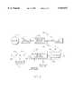
- FIG. 3comprises a schematic diagram of the bidirectional converter and inverter of FIG. 2.
- FIG. 1illustrates a prior art starting/generating system 10 which may be used in, for example, a small business aircraft.
- a prime mover in the form of an aircraft jet engine 12is coupled to a first pad of an engine gear box 14.
- a DC starter/generator 16is coupled to the engine gear box 14. During operation in a starting mode, the DC starter/generator 16 receives DC power developed by a battery 18 or other DC power source via contactors K1 such that the starter/generator 16 is operated as a motor to provide motive power to the engine 12.
- the jet engine 12may thereafter supply motive power to the DC starter/generator 16 during operation in a generating mode to cause it to develop DC power which is supplied by the contactors K1 and a further set of contactors K2 to a DC load bus 20.
- the system 10further includes an AC generator 22 having an exciter portion 24 and a wound-field main generator portion 26.
- a rotor of the AC generator 22is coupled to a second pad of the engine gear box 14 and develops AC power which is coupled by a set of contactors K3 to frequency-insensitive loads, such as de-ice segments or elements, over a bus 28.
- frequency-insensitive loadssuch as de-ice segments or elements
- a generator control unit (GCU) 30is responsive to the DC power on a line 32 between contactors K1 and K2 and further is responsive to the state of a switch located in the aircraft cockpit (not shown) and provides regulated power to the exciter 24.
- the GCU 30also controls the contactor sets K1-K3 in the starting and generating modes such that, in the starting mode, the contactors K1 are closed and the contactor sets K2 and K3 are opened and such that the contactor sets K1-K3 are all closed during operation in the generating mode.
- FIG. 2illustrates a starting/generating system 40 according to the present invention which is coupled to the engine 12 and gear box 14.
- a permanent magnet generator (PMG) 42is coupled to a single pad of the gear box 14 and supplies power to the various loads.
- the PMG 42is coupled to a set of single or polyphase lines or conductors 44 forming an AC power bus 44.
- the PMG 42develops three-phase power which is coupled by the lines 44 to contactor sets K4 and K5.
- the contactor set K4is in turn coupled to a set of variable voltage/variable frequency AC loads, such as de-ice segments, galley loads, etc.
- the contactor set K5is coupled to a first set of inputs/outputs 46 of a power converter 48.
- the power converter 48includes a second set of input/outputs 50 which are in turn coupled by contactor sets K6 and K7 to conductors or lines forming a DC load bus 52.
- a battery 54 or other DC power sourceis coupled to conductors intermediate the contactors K6 and K7.
- the power converter 48comprises an inverter 56, which is capable of bidirectional power flow, and a bidirectional DC-DC converter 58 coupled to the inverter 56.
- the inverter 56includes an inverter control which operates switches in the inverter 56.
- the DC-DC converter 58includes a converter control which controls switches in the converter 58 in response to the state of a switch or switches in the cockpit (not shown) of the aircraft.
- the bidirectional DC-DC converter 58includes controls to operate the contactors K4-K7 in response to system status and protection functions and cockpit switch commands. During operation in the starting mode, the contactors K4 and K7 are opened while the contactors K5 and K6 are closed.
- DC poweris supplied by the battery through the contactor set K6 to the bidirectional DC-DC converter 58, which steps up the DC voltage to a level of, for example, approximately 150 to 270 volts DC.
- the inverter 56is operated by the inverter control to develop AC power of suitable waveshape to cause the PMG 42 to operate as a motor and bring the engine 12 up to self-sustaining speed.
- the system 10does not require a position sensor for the PMG 42, inasmuch as voltage and frequency can be slowly applied at stall at the beginning of the starting sequence. Position or speed sensing may be required, however, if in-flight restart capability at a variety of PMG speeds is to be implemented.
- power for startingmay be supplied by an external power source, such as a ground power cart, in which case additional contactors would be required.
- DC-DC converter 58During operation in the generating mode, all of the contactors K4-K7 are closed by the DC-DC converter 58, provided there is no load shorts or other faults occurring.
- AC power on the AC bus 44is supplied to the AC loads and the inverter 56 rectifies the AC power into DC power and the DC power is level shifted to a voltage of, for example, 28 volts DC by the DC-DC converter 58.
- This DC powermay be supplied on the DC bus 52 to one or more DC loads and, if desired, may be used to charge the battery 54.
- FIG. 3illustrates the inverter 56 and the DC-DC converter 58 in greater detail.
- the DC-DC converter 58includes first and second pairs of controllable power switches Q1, Q2 and Q3, Q4.
- the controllable power switches Q1-Q4may comprise power MOSFET arrays, IGBT's or any other controllable switches of suitable power rating.
- a flyback/rectifier diode CR1-CR4is coupled across each of the switches Q1-Q4, respectively.
- the power switches Q1 and Q2are coupled to first and second ends, respectively, of a first winding W1 of a transformer T1.
- the switches Q3 and Q4are coupled to first and second ends of a second winding W2 of the transformer T1 which is magnetically linked with the first winding W1.
- a mid-tap of the first winding W1is coupled by the contactors K6 to the battery 54.
- a mid-tap of the second winding W2is coupled to a first DC conductor 60, which is in turn coupled together with a second DC conductor 62 to the inverter 56.
- a capacitor C1is coupled across the DC conductor 60, 62 to provide transient suppression and a small amount of energy storage for PWM filtering.
- the inverter 56comprises pairs of controllable power switches Q5, Q6 and Q7, Q8 and Q9, Q10 which are coupled in a conventional three-phase bridge configuration across the DC conductors 60 and 62.
- the power switches Q5-Q10may be power MOFSET arrays, IGBT's or any other controllable switch of suitable power rating.
- Flyback/rectifier diodes CR5-CR10are coupled across the controllable switches Q5-Q10, respectively.
- Contacts K5a-K5c of the contactor K5are coupled to junctions 70a, 70b and 70c between the switches of each pair.
- the contacts K5a-K5care further coupled to armature windings 72a-72c, respectively, of the PMG 42.
- Contacts K4a-K4c of the contactor K4are coupled between conductors 44a-44c of the AC bus 44 (which are coupled to the PMG armature windings 72a-72c, respectively,) and the AC load(s
- the switches Q1 and Q2are alternately operated in a pulse-width modulated (PWM) or quasi-square wave mode of operation at a selected frequency of, for example, 20 KHz.
- PWMpulse-width modulated
- This AC poweris rectified by the diodes CR3 and CR4 to develop DC power across the DC conductors 60 and 62.
- the controllable power switches Q5-Q10are operated in a pulse-width modulated mode of operation to bring the PMG 42, and thus the aircraft engine 12, up to speed in a controlled fashion, such as in a nearly constant volt-second/cycle mode of operation.
- AC power developed in the armature windings 72a-72c of the PMG 42is rectified by the diodes CR5-CR10 to develop DC power across the DC conductors 60 and 62.
- the switches Q5-Q10are preferably off.
- the switches Q5-Q10can be operated to form a controlled voltage active rectifier circuit.
- the controllable power switches Q3 and Q4 in the DC-DC converter 58are alternately operated in a PWM mode to convert the DC power 60 appearing across the DC conductors 60 and 62 into intermediate AC power across the winding W1 and to regulate the output of the DC-DC converter 28.
- the switches Q1 and Q2are maintained in an off condition, and the intermediate AC power is rectified by the diodes CR1 and CR2.
- the resulting DC poweris supplied by the contactors K6 to the battery 54 and by the contactors K7 to the DC loads 52.
- the contacts K4a-K4care closed so that the AC loads receive the AC power on the AC bus 44.
- the power developed by the PMG 42must be sufficient at low operating frequencies and voltages to perform the worst case de-ice function. As frequency and voltage increase, the thermally controlled loads have an increasing off-time to maintain the de-ice condition.
- the power switches Q3 and Q4can be operated in a pulse-width modulated mode of operation or in a quasi square wave mode of operation to convert the DC voltage appearing across the DC conductors 60 and 62 into regulated 28 volt DC power for the battery 54 and the loads on the DC load bus 52.
- FIG. 2A comparison of FIG. 2 with FIG. 1 illustrates the advantages of the present invention.
- the starting/generating system 40 of FIG. 2requires only one generator, which is inherently more reliable than the two electromagnetic machines 16 and 22 of FIG. 1 alone or in combination. Further, only one gear box pad is required.
- the permanent magnet generator 42does not utilize brushes, which are a high maintenance item, and overall weight is reduced.
Landscapes
- Engineering & Computer Science (AREA)
- Power Engineering (AREA)
- Control Of Eletrric Generators (AREA)
Abstract
Description
The present invention relates generally to starting/generating systems, and more particularly to a starting/generating system for an aircraft.
In a small business aircraft, a DC starter/generator is utilized in a starting mode to convert DC power supplied by a battery into motive power for starting main engines. Thereafter, the starter/generator is operable in a generating mode to provide up to a maximum current rating at a particular voltage, such as 200-400 amps at 28 volts DC. Engine start power requirements have grown over time, resulting in increasing unreliability of the DC starter/generator. In addition, loads have also increased, leading to the need to add a separate wound-field AC generator to the engine to supply a portion of the loads. This, in turn, results in the need for two gear box pads to drive the two types of generators. Further, the DC starter/generator is a source of high life cycle costs due to maintenance of the brushes thereof.
The addition of a further machine to the engine gear box to supply power to loads results in reduced reliability of the overall system.
A main engine starting generating system eliminates both the DC starter/generator and the AC generator of the conventional system and replaces same with a permanent magnet generator (PMG) and associated electronics. Weight is thus decreased and reliability is improved as compared with existing systems.
More particularly, a starting/generating system for use with a prime mover and operable in a starting mode to start the prime mover and further operable in a generating mode to develop power for loads includes a PMG having a motive power shaft coupled to the prime mover and further having a winding, a bidirectional power converter having first and second inputs and a DC power bus coupled to the power converter first input/output. A DC power source is coupled to the first power bus and an AC power bus is coupled between the power converter second input/output and the PMG winding. A converter control is coupled to the power converter wherein the converter control causes the power converter to convert power delivered by the DC power source to the DC power bus into power for the PMG during operation in the starting mode. The converter control causes the power converter to convert power developed by the PMG on the AC power bus into power for the DC power bus during operation in the generating mode.
Preferably, the power converter includes an inverter coupled to the PMG winding and a bidirectional DC-DC converter coupled between the inverter and the DC power bus.
Also preferably, the DC-DC converter comprises a transformer having first and second windings, a first pair of controllable power switches coupled to ends of the first winding, a second pair of controllable power switches coupled to the ends of the second windings, and diodes coupled across the controllable power switches.
Still further in accordance with the preferred embodiment, the inverter includes controllable power switches coupled to the PMG winding and further coupled across DC conductors. In addition, contactors may be provided for selectively coupling the PMG to an AC load during operation in the generating mode.
In accordance with alternative embodiments, the DC-DC converter is operated in a pulse-width-modulated mode of operation or a quasi square wave mode of operation.
In accordance with a further aspect of the present invention, a starting/generating system for use with an aircraft engine and operable in a starting mode to start the aircraft engine and further operable in a generating mode to develop power for aircraft loads includes a PMG having a motive power shaft coupled to the aircraft engine and further having a set of polyphase windings. An inverter is coupled to the set of PMG polyphase windings and a bidirectional DC-DC converter is coupled to the inverter. A DC bus is coupled to the DC-DC converter and a battery is coupled to the DC bus. A converter control is coupled to the inverter and causes the DC-DC converter and the inverter to convert DC power provided by the battery into AC power for the PMG during operation in the starting mode. The converter control further causes the inverter and the DC-DC converter to develop DC power for the power bus during operation in the generating mode.
In accordance with yet another aspect of the present invention, a starting/generating system for use with an aircraft engine and operable in a starting mode to start the aircraft engine and further operable in a generating mode to develop power for aircraft loads includes a PMG having a motive power shaft coupled to the aircraft engine and further having a set of polyphase windings and an inverter including controllable power switches coupled across DC conductors. A bidirectional DC-DC converter is coupled to the DC conductors and includes a transformer having first and second windings, a first pair of controllable power switches coupled to ends of the first winding, a second pair of controllable power switches coupled to ends of the second windings and diodes coupled across the controllable power switches. A DC bus is coupled to the DC-DC converter and a battery is coupled to the DC bus and develops a battery voltage. The DC-DC converter steps up the battery voltage in the starting mode and further produces a substantially constant DC voltage on the DC bus during operation in the generating mode. Contactors are coupled between the PMG and AC loads, and means are provided for closing the contactors during operation in the generating mode so that power developed by the PMG is delivered to the AC loads. A converter control is coupled to the inverter wherein the converter control causes the DC converter and the inverter to convert DC power provided by the battery into AC power for the PMG during operation in the starting mode. The converter control further causes the inverter and the DC-DC converter to develop DC power for the power bus during operation in the generating mode.
Other features and advantages are inherent in the apparatus claimed and disclosed or will become apparent to those skilled in the art from the following detailed description in conjunction with the accompanying drawings.
FIG. 1 comprises a simplified block diagram of a prior art starting/generating system;
FIG. 2 comprises a block diagram of a starting/generating system according to the present invention; and
FIG. 3 comprises a schematic diagram of the bidirectional converter and inverter of FIG. 2.
FIG. 1 illustrates a prior art starting/generatingsystem 10 which may be used in, for example, a small business aircraft. A prime mover in the form of anaircraft jet engine 12 is coupled to a first pad of anengine gear box 14. A DC starter/generator 16 is coupled to theengine gear box 14. During operation in a starting mode, the DC starter/generator 16 receives DC power developed by a battery 18 or other DC power source via contactors K1 such that the starter/generator 16 is operated as a motor to provide motive power to theengine 12. Once self-sustaining speed is achieved, thejet engine 12 may thereafter supply motive power to the DC starter/generator 16 during operation in a generating mode to cause it to develop DC power which is supplied by the contactors K1 and a further set of contactors K2 to aDC load bus 20.
Thesystem 10 further includes anAC generator 22 having anexciter portion 24 and a wound-fieldmain generator portion 26. A rotor of theAC generator 22 is coupled to a second pad of theengine gear box 14 and develops AC power which is coupled by a set of contactors K3 to frequency-insensitive loads, such as de-ice segments or elements, over abus 28. It should be noted that, while single lines between elements are shown in the Figs. (such as the line 28), in reality each may consist of a number of conductors (such as three), one for each phase of AC power.
A generator control unit (GCU) 30 is responsive to the DC power on aline 32 between contactors K1 and K2 and further is responsive to the state of a switch located in the aircraft cockpit (not shown) and provides regulated power to theexciter 24.
The GCU 30 also controls the contactor sets K1-K3 in the starting and generating modes such that, in the starting mode, the contactors K1 are closed and the contactor sets K2 and K3 are opened and such that the contactor sets K1-K3 are all closed during operation in the generating mode.
FIG. 2 illustrates a starting/generatingsystem 40 according to the present invention which is coupled to theengine 12 andgear box 14. In this system, a permanent magnet generator (PMG) 42 is coupled to a single pad of thegear box 14 and supplies power to the various loads. Specifically, the PMG 42 is coupled to a set of single or polyphase lines orconductors 44 forming anAC power bus 44. In the preferred embodiment, thePMG 42 develops three-phase power which is coupled by thelines 44 to contactor sets K4 and K5. The contactor set K4 is in turn coupled to a set of variable voltage/variable frequency AC loads, such as de-ice segments, galley loads, etc. The contactor set K5 is coupled to a first set of inputs/outputs 46 of apower converter 48. Thepower converter 48 includes a second set of input/outputs 50 which are in turn coupled by contactor sets K6 and K7 to conductors or lines forming aDC load bus 52. Abattery 54 or other DC power source is coupled to conductors intermediate the contactors K6 and K7.
Thepower converter 48 comprises aninverter 56, which is capable of bidirectional power flow, and a bidirectional DC-DC converter 58 coupled to theinverter 56. Theinverter 56 includes an inverter control which operates switches in theinverter 56. In addition, the DC-DC converter 58 includes a converter control which controls switches in theconverter 58 in response to the state of a switch or switches in the cockpit (not shown) of the aircraft. Further, the bidirectional DC-DC converter 58 includes controls to operate the contactors K4-K7 in response to system status and protection functions and cockpit switch commands. During operation in the starting mode, the contactors K4 and K7 are opened while the contactors K5 and K6 are closed. DC power is supplied by the battery through the contactor set K6 to the bidirectional DC-DC converter 58, which steps up the DC voltage to a level of, for example, approximately 150 to 270 volts DC. During this time, theinverter 56 is operated by the inverter control to develop AC power of suitable waveshape to cause thePMG 42 to operate as a motor and bring theengine 12 up to self-sustaining speed. Significantly, thesystem 10 does not require a position sensor for thePMG 42, inasmuch as voltage and frequency can be slowly applied at stall at the beginning of the starting sequence. Position or speed sensing may be required, however, if in-flight restart capability at a variety of PMG speeds is to be implemented.
If desired, power for starting may be supplied by an external power source, such as a ground power cart, in which case additional contactors would be required.
During operation in the generating mode, all of the contactors K4-K7 are closed by the DC-DC converter 58, provided there is no load shorts or other faults occurring. AC power on theAC bus 44 is supplied to the AC loads and theinverter 56 rectifies the AC power into DC power and the DC power is level shifted to a voltage of, for example, 28 volts DC by the DC-DC converter 58. This DC power may be supplied on theDC bus 52 to one or more DC loads and, if desired, may be used to charge thebattery 54.
FIG. 3 illustrates theinverter 56 and the DC-DC converter 58 in greater detail. The DC-DC converter 58 includes first and second pairs of controllable power switches Q1, Q2 and Q3, Q4. The controllable power switches Q1-Q4 may comprise power MOSFET arrays, IGBT's or any other controllable switches of suitable power rating. A flyback/rectifier diode CR1-CR4 is coupled across each of the switches Q1-Q4, respectively. The power switches Q1 and Q2 are coupled to first and second ends, respectively, of a first winding W1 of a transformer T1. The switches Q3 and Q4 are coupled to first and second ends of a second winding W2 of the transformer T1 which is magnetically linked with the first winding W1. A mid-tap of the first winding W1 is coupled by the contactors K6 to thebattery 54. A mid-tap of the second winding W2 is coupled to afirst DC conductor 60, which is in turn coupled together with asecond DC conductor 62 to theinverter 56. A capacitor C1 is coupled across theDC conductor
Theinverter 56 comprises pairs of controllable power switches Q5, Q6 and Q7, Q8 and Q9, Q10 which are coupled in a conventional three-phase bridge configuration across theDC conductors junctions armature windings 72a-72c, respectively, of thePMG 42. Contacts K4a-K4c of the contactor K4 are coupled betweenconductors 44a-44c of the AC bus 44 (which are coupled to thePMG armature windings 72a-72c, respectively,) and the AC load(s).
During operation in the starting mode, the switches Q1 and Q2 are alternately operated in a pulse-width modulated (PWM) or quasi-square wave mode of operation at a selected frequency of, for example, 20 KHz. AC power is thereby developed across the winding W1, in turn causing a corresponding AC waveform to be developed across the winding W2. This AC power is rectified by the diodes CR3 and CR4 to develop DC power across theDC conductors PMG 42, and thus theaircraft engine 12, up to speed in a controlled fashion, such as in a nearly constant volt-second/cycle mode of operation.
During operation in the generating mode, AC power developed in thearmature windings 72a-72c of thePMG 42 is rectified by the diodes CR5-CR10 to develop DC power across theDC conductors DC converter 58 are alternately operated in a PWM mode to convert theDC power 60 appearing across theDC conductors DC converter 28. During operation in the generating mode, the switches Q1 and Q2 are maintained in an off condition, and the intermediate AC power is rectified by the diodes CR1 and CR2. The resulting DC power is supplied by the contactors K6 to thebattery 54 and by the contactors K7 to the DC loads 52.
In addition to the foregoing, during operation in the generating mode, the contacts K4a-K4c are closed so that the AC loads receive the AC power on theAC bus 44. The power developed by thePMG 42 must be sufficient at low operating frequencies and voltages to perform the worst case de-ice function. As frequency and voltage increase, the thermally controlled loads have an increasing off-time to maintain the de-ice condition.
It should be noted that the power switches Q3 and Q4 can be operated in a pulse-width modulated mode of operation or in a quasi square wave mode of operation to convert the DC voltage appearing across theDC conductors battery 54 and the loads on theDC load bus 52.
A comparison of FIG. 2 with FIG. 1 illustrates the advantages of the present invention. The starting/generating system 40 of FIG. 2 requires only one generator, which is inherently more reliable than the twoelectromagnetic machines permanent magnet generator 42 does not utilize brushes, which are a high maintenance item, and overall weight is reduced.
Numerous modifications to the present invention will be apparent to those skilled in the art in view of the foregoing description. Accordingly, this description is to be construed as illustrative only and is presented for the purpose of enabling those skilled in the art to make and use the invention and to teach the best mode of carrying out same. The exclusive rights of all modifications which come within the scope of the appended claims are reserved.
Claims (16)
1. A starting/generating system for use with a prime mover and operable in a starting mode to start the prime mover and further operable in a generating mode to develop power for loads, comprising:
a permanent magnet generator (PMG) having a motive power shaft coupled to the prime mover and further having a winding;
a bidirectional power converter having first and second inputs/outputs;
a DC power bus coupled to the power converter first input/output;
a DC power source coupled to the DC power bus;
an AC power bus coupled between the power converter second input/output and the PMG winding;
an AC load coupled to the AC power bus and receiving power from the PMG during operation in the generating mode; and
a converter control coupled to the power converter wherein the converter control causes the power converter to convert power delivered by the DC power source to the DC power bus into power for the PMG during operation in the starting mode and which causes the power converter to convert power developed by the PMG on the AC power bus into power for the DC power bus during operation in the generating mode.
2. The starting/generating system of claim 1, wherein the power converter includes an inverter coupled to the PMG winding and a bidirectional DC-DC converter coupled between the inverter and the DC power bus.
3. The starting/generating system of claim 2, wherein the DC-DC converter comprises a transformer having first and second windings, a first pair of controllable power switches coupled to ends of the first winding, a second pair of controllable power switches coupled to ends of the second winding and diodes coupled across the controllable power switches.
4. The starting/generating system of claim 2, wherein the inverter includes controllable power switches coupled to the PMG winding and further coupled across DC conductors.
5. The starting/generating system of claim 1, further including contactors for selectively coupling the PMG to AC loads during operation in the generating mode.
6. The starting/generating system of claim 2, wherein the converter control comprises means for operating the DC-DC converter in a pulse-width modulated mode of operation.
7. The starting/generating system of claim 2, wherein the converter control comprises means for operating the DC-DC converter in a quasi square wave mode of operation.
8. A starting/generating system for use with an aircraft engine and operable in a starting mode to start the aircraft engine and further operable in a generating mode to develop power for aircraft loads, comprising:
a permanent magnet generator (PMG) having a motive power shaft coupled to the aircraft engine and further having a set of polyphase windings;
an AC load coupled to the set of polyphase windings and receiving AC power from the PMG during operation in the generating mode;
an inverter coupled to the set of PMG polyphase windings;
a bidirectional DC-DC converter coupled to the inverter;
a DC bus coupled to the DC-DC converter;
a battery coupled to the DC bus; and
a converter control coupled to the inverter wherein the converter control causes the DC-DC converter and the inverter to convert DC power provided by the battery into AC power for the PMG during operation in the starting mode and which causes the inverter and the DC-DC converter to develop DC power for the power bus during operation in the generating mode.
9. The starting/generating system of claim 8, wherein the DC-DC converter comprises a transformer having first and second windings, a first pair of controllable power switches coupled to ends of the first winding, a second pair of controllable power switches coupled to ends of the second winding and diodes coupled across the controllable power switches.
10. The starting/generating system of claim 9, wherein the inverter includes controllable power switches coupled to the PMG winding and further coupled across DC conductors.
11. The starting/generating system of claim 10, further including contactors for selectively coupling the PMG to AC loads during operation in the generating mode.
12. The starting/generating system of claim 11, wherein the converter control comprises means for operating the DC-DC converter in a pulse-width modulated mode of operation.
13. The starting/generating system of claim 11, wherein the converter control comprises means for operating the DC-DC converter in a quasi square wave mode of operation.
14. A starting/generating system for use with an aircraft engine and operable in a starting mode to start the aircraft engine and further operable in a generating mode to develop power for aircraft loads, comprising:
a permanent magnet generator (PMG) having a motive power shaft coupled to the aircraft engine and further having a set of polyphase windings;
an inverter including controllable power switches coupled across DC conductors;
a bidirectional DC-DC converter coupled to the DC conductors and comprising a transformer having first and second windings, a first pair of controllable power switches coupled to ends of the first winding, a second pair of controllable power switches coupled to ends of the second winding and diodes coupled across the controllable power switches;
a DC bus coupled to the DC-DC converter;
a battery coupled to the DC bus and developing a battery voltage;
wherein the DC-DC converter steps up the battery voltage in the starting mode and produces a substantially constant DC voltage on the DC bus during operation in the generating mode;
contactors coupled between the PMG and AC loads;
means for closing the contactors during operation in the generating mode so that power developed by the PMG is delivered to the AC loads; and
a converter control coupled to the inverter wherein the converter control causes the DC-DC converter and the inverter to convert DC power provided by the battery into AC power for the PMG during operation in the starting mode and which causes the inverter and the DC-DC converter to develop DC power for the power bus during operation in the generating mode.
15. The starting/generating system of claim 14, wherein the converter control comprises means for operating the DC-DC converter in a pulse-width modulated mode of operation.
16. The starting/generating system of claim 14, wherein the converter control comprises means for operating the DC-DC converter in a quasi square wave mode of operation.
Priority Applications (1)
| Application Number | Priority Date | Filing Date | Title |
|---|---|---|---|
| US08/885,312US5929537A (en) | 1997-06-30 | 1997-06-30 | PMG main engine starter/generator system |
Applications Claiming Priority (1)
| Application Number | Priority Date | Filing Date | Title |
|---|---|---|---|
| US08/885,312US5929537A (en) | 1997-06-30 | 1997-06-30 | PMG main engine starter/generator system |
Publications (1)
| Publication Number | Publication Date |
|---|---|
| US5929537Atrue US5929537A (en) | 1999-07-27 |
Family
ID=25386622
Family Applications (1)
| Application Number | Title | Priority Date | Filing Date |
|---|---|---|---|
| US08/885,312Expired - LifetimeUS5929537A (en) | 1997-06-30 | 1997-06-30 | PMG main engine starter/generator system |
Country Status (1)
| Country | Link |
|---|---|
| US (1) | US5929537A (en) |
Cited By (74)
| Publication number | Priority date | Publication date | Assignee | Title |
|---|---|---|---|---|
| US5998976A (en)* | 1996-11-08 | 1999-12-07 | Robert Bosch Gmbh | Power supply system |
| US6414402B1 (en)* | 1999-03-09 | 2002-07-02 | Bayerische Motoren Werke Aktiengesellschaft | Motor vehicle starter monitoring system with automatic control unit activation |
| US6487096B1 (en)* | 1997-09-08 | 2002-11-26 | Capstone Turbine Corporation | Power controller |
| US6486568B1 (en)* | 1999-12-21 | 2002-11-26 | General Electric Company | Power system using a multi-functional power interface unit |
| US20020175522A1 (en)* | 2001-01-30 | 2002-11-28 | Joel Wacknov | Distributed power system |
| US20020198648A1 (en)* | 1998-01-05 | 2002-12-26 | Mark Gilbreth | Method and system for control of turbogenerator power and temperature |
| US20030015873A1 (en)* | 2001-01-10 | 2003-01-23 | Claude Khalizadeh | Transient ride-through or load leveling power distribution system |
| US6577026B1 (en)* | 1998-03-11 | 2003-06-10 | Ballard Power Systems Ag | Circuit arrangement for supplying electric power to a network comprising a fuel cell and an accumulator system |
| US6612112B2 (en) | 1998-12-08 | 2003-09-02 | Capstone Turbine Corporation | Transient turbine exhaust temperature control for a turbogenerator |
| US20040012204A1 (en)* | 2002-06-06 | 2004-01-22 | Walter Richard T. | Starter system for portable internal combustion engine electric generators using a portable universal battery pack |
| US20040080300A1 (en)* | 2002-10-23 | 2004-04-29 | Mingzhou Xu | Gas turbine engine starter-generator exciter starting system and method |
| US20040119291A1 (en)* | 1998-04-02 | 2004-06-24 | Capstone Turbine Corporation | Method and apparatus for indirect catalytic combustor preheating |
| US20040135436A1 (en)* | 1998-04-02 | 2004-07-15 | Gilbreth Mark G | Power controller system and method |
| US20040148942A1 (en)* | 2003-01-31 | 2004-08-05 | Capstone Turbine Corporation | Method for catalytic combustion in a gas- turbine engine, and applications thereof |
| US6784565B2 (en) | 1997-09-08 | 2004-08-31 | Capstone Turbine Corporation | Turbogenerator with electrical brake |
| US20050012339A1 (en)* | 2003-05-07 | 2005-01-20 | Mikhail Amir S. | Variable speed distributed drive train wind turbine system |
| US20050031944A1 (en)* | 2003-08-06 | 2005-02-10 | Sodemann Wesley C. | Portable power source |
| US20050237034A1 (en)* | 2004-04-23 | 2005-10-27 | Patterson Stanley C | Fault tolerant architecture for permanent magnet starter generator subsystem |
| US6960840B2 (en) | 1998-04-02 | 2005-11-01 | Capstone Turbine Corporation | Integrated turbine power generation system with catalytic reactor |
| US20060017328A1 (en)* | 2003-02-10 | 2006-01-26 | Bryde Jan H | Control system for distributed power generation, conversion, and storage system |
| US20060066104A1 (en)* | 2004-09-30 | 2006-03-30 | Melfi Michael J | Methods and apparatus for ride-through operation of a complementary device to a transient power source |
| US20060119177A1 (en)* | 2004-12-02 | 2006-06-08 | Kumar Ajith K | Locomotive auxiliary power system |
| US20060170218A1 (en)* | 2002-06-06 | 2006-08-03 | Grant Jeffrey P | Starter system for portable internal combustion engine electric generators using a portable universal battery pack |
| WO2006087379A1 (en)* | 2005-02-17 | 2006-08-24 | Hispano Suiza | Electric supply for an aircraft gas turbine engine equipment |
| US20060202588A1 (en)* | 2005-02-12 | 2006-09-14 | Min-Huang Lin | Coreless generator set |
| US7112944B1 (en)* | 2005-04-19 | 2006-09-26 | Honeywell International Inc. | Electrical power system for multi-use power conditioning and engine start |
| US20060244425A1 (en)* | 2003-06-13 | 2006-11-02 | Christof Sihler | Method and damping device for damping a torsional vibration in a rotating drivetrain |
| US20060261783A1 (en)* | 2005-05-23 | 2006-11-23 | Paul Gamboa | Electronic battery module (EBM) with bidirectional DC-DC converter |
| US20070029804A1 (en)* | 2005-08-05 | 2007-02-08 | Siemens Westinghouse Power Corporation | Electric power generation system using a permanent magnet dynamoelectric machine for starting a combustion turbine and for generating uninterruptible excitation power |
| US20070120366A1 (en)* | 2002-06-06 | 2007-05-31 | Grant Jeffrey P | Starter system for portable internal combustion engine electric generators using a portable universal battery pack |
| FR2899202A1 (en)* | 2006-04-04 | 2007-10-05 | Airbus France Sas | Emergency electric energy generation device for e.g. civil transport plane, has air conditioning plants used as emergency electric generators and with air compressors that are power reversible, and power storage device with sub-assemblies |
| EP1852953A1 (en)* | 2006-05-05 | 2007-11-07 | Hispano-Suiza | Device for supplying electric energy to an aircraft |
| US20080093850A1 (en)* | 2006-06-14 | 2008-04-24 | Smiths Aerospace Llc | Dual-structured aircraft engine starter/generator |
| US7400117B1 (en)* | 2007-06-20 | 2008-07-15 | Hamilton Sundstrand Corporation | Generating system with a regulated permanent magnet machine and an active rectifier |
| US20080179961A1 (en)* | 2007-01-26 | 2008-07-31 | Kimball Jonathan W | Apparatus and method for controlling a power supply |
| US20090015065A1 (en)* | 2004-07-30 | 2009-01-15 | Michael Anthony Becigneul | Centralized powering system and method |
| WO2008139096A3 (en)* | 2007-04-06 | 2009-03-26 | Turbomeca | Helicopter turboshaft engine comprising a gas generator and a free turbine |
| USRE40713E1 (en) | 1997-09-08 | 2009-05-19 | Capstone Turbine Corporation | Turbogenerator/motor controller |
| US20090179499A1 (en)* | 2004-01-21 | 2009-07-16 | Nextek Power Systems, Inc. | Multiple bi-directional input/output power control system |
| US20090230927A1 (en)* | 2008-03-14 | 2009-09-17 | Astronics Advanced Electronic Systems Corp., A Corporation Of The State Of Washington | Fault clearing method for permanent magnet machines |
| US20090295169A1 (en)* | 2002-06-06 | 2009-12-03 | Black& Decker Inc. | Starter system for portable internal combustion engine electric generators using a portable universal battery pack |
| US7782626B2 (en) | 2007-02-02 | 2010-08-24 | Black & Decker Inc. | Portable power driven system with battery anti-theft apparatus |
| US20100283319A1 (en)* | 2007-01-31 | 2010-11-11 | Hispano Suiza | Electrical power supply circuit in an aircraft for electrical equipment including a de-icing circuit |
| US20100283242A1 (en)* | 2007-12-26 | 2010-11-11 | Dooley Kevin A | High Voltage Start of an Engine from a Low Voltage Battery |
| US20110012543A1 (en)* | 2009-07-17 | 2011-01-20 | Fuji Electric Systems Co., Ltd. | Electric power converter |
| US20110020523A1 (en)* | 2008-07-15 | 2011-01-27 | Pepsico, Inc. | Method for Preparing a Low Viscosity Whole Grain Flour Slurry Via Mechanical Treatment |
| US20110037442A1 (en)* | 2006-05-22 | 2011-02-17 | Vertoco Ltd | Permanent magnet generator control |
| EP2306610A1 (en)* | 2009-09-30 | 2011-04-06 | Siemens Aktiengesellschaft | System to store and to transmit electrical power |
| US20110083733A1 (en)* | 2009-10-12 | 2011-04-14 | SolarBridge Technologies | Power inverter docking system for photovoltaic modules |
| US7989969B2 (en) | 2002-06-06 | 2011-08-02 | Black & Decker Inc. | Universal power tool battery pack coupled to a portable internal combustion engine |
| US8174856B2 (en) | 2011-04-27 | 2012-05-08 | Solarbridge Technologies, Inc. | Configurable power supply assembly |
| US8232702B2 (en) | 2010-07-30 | 2012-07-31 | Ge Aviation Systems, Llc | Apparatus for a high speed sleeveless rotor |
| US8279649B2 (en) | 2010-10-11 | 2012-10-02 | Solarbridge Technologies, Inc. | Apparatus and method for controlling a power inverter |
| US8284574B2 (en) | 2011-10-17 | 2012-10-09 | Solarbridge Technologies, Inc. | Method and apparatus for controlling an inverter using pulse mode control |
| US8325499B2 (en) | 2007-10-11 | 2012-12-04 | Solarbridge Technologies, Inc. | Methods for minimizing double-frequency ripple power in single-phase power conditioners |
| US8503200B2 (en) | 2010-10-11 | 2013-08-06 | Solarbridge Technologies, Inc. | Quadrature-corrected feedforward control apparatus and method for DC-AC power conversion |
| US8581425B2 (en) | 2010-10-22 | 2013-11-12 | Hamilton Sundstrand Corporation | Systems and methods involving electrical start and power generation |
| US20130320763A1 (en)* | 2012-06-01 | 2013-12-05 | Hamilton Sundstrand Corporation | Dual generator system |
| US8611107B2 (en) | 2011-04-27 | 2013-12-17 | Solarbridge Technologies, Inc. | Method and system for controlling a multi-stage power inverter |
| US8824178B1 (en) | 2009-12-31 | 2014-09-02 | Solarbridge Technologies, Inc. | Parallel power converter topology |
| US8842454B2 (en) | 2010-11-29 | 2014-09-23 | Solarbridge Technologies, Inc. | Inverter array with localized inverter control |
| US8922185B2 (en) | 2011-07-11 | 2014-12-30 | Solarbridge Technologies, Inc. | Device and method for global maximum power point tracking |
| US9065354B2 (en) | 2011-04-27 | 2015-06-23 | Sunpower Corporation | Multi-stage power inverter for power bus communication |
| US9093919B2 (en) | 2009-07-31 | 2015-07-28 | Sunpower Corporation | Apparatus for converting direct current to alternating current using a frequency converter |
| US9160408B2 (en) | 2010-10-11 | 2015-10-13 | Sunpower Corporation | System and method for establishing communication with an array of inverters |
| US9276635B2 (en) | 2012-06-29 | 2016-03-01 | Sunpower Corporation | Device, system, and method for communicating with a power inverter using power line communications |
| US20160118788A1 (en)* | 2008-10-01 | 2016-04-28 | Aspen Avionics, Inc. | Airborne power system disconnect system and method |
| US9467063B2 (en) | 2010-11-29 | 2016-10-11 | Sunpower Corporation | Technologies for interleaved control of an inverter array |
| US20160304214A1 (en)* | 2015-04-20 | 2016-10-20 | Hamilton Sundstrand Corporation | Emergency power sources for propulsion systems |
| US9509231B2 (en) | 2012-04-26 | 2016-11-29 | General Electric Company | Power converter system, damping system, and method of operating a power converter system |
| US9564835B2 (en) | 2013-03-15 | 2017-02-07 | Sunpower Corporation | Inverter communications using output signal |
| US9584044B2 (en) | 2013-03-15 | 2017-02-28 | Sunpower Corporation | Technologies for converter topologies |
| FR3089709A1 (en)* | 2018-12-06 | 2020-06-12 | Safran Electrical & Power | Management system for electrical interruptions in the electrical network of an aircraft |
| US10723469B2 (en) | 2018-09-21 | 2020-07-28 | Hamilton Sunstrand Corporation | System and method for driving electrically driving a gas turbine engine via a wound field synchronous machine assisted by a PMG |
Citations (15)
| Publication number | Priority date | Publication date | Assignee | Title |
|---|---|---|---|---|
| US2908776A (en)* | 1957-02-07 | 1959-10-13 | Cutler Hammer Inc | Operating means for electric circuit controlling devices |
| US3132297A (en)* | 1961-02-14 | 1964-05-05 | Sundstrand Corp | Field circuit control |
| US3519843A (en)* | 1967-11-17 | 1970-07-07 | Clark Equipment Co | Electrical power supply system |
| US3555290A (en)* | 1969-05-29 | 1971-01-12 | Walter Ellermeyer | Second-highest redundant voltage selector |
| US4356402A (en)* | 1980-06-05 | 1982-10-26 | Nippon Electric Co., Ltd. | Engine generator power supply system |
| US4467220A (en)* | 1977-07-15 | 1984-08-21 | Ronald Page | Power switching apparatus |
| US4638175A (en)* | 1984-07-03 | 1987-01-20 | United Technologies Corporation | Electric power distribution and load transfer system |
| US4659942A (en)* | 1985-06-03 | 1987-04-21 | The Charles Stark Draper Laboratory, Inc. | Fault-tolerant power distribution system |
| US4743776A (en)* | 1986-09-02 | 1988-05-10 | Sundstrand Corporation | Starter-generator for engines |
| US4830412A (en)* | 1987-10-26 | 1989-05-16 | Sundstrand Corporation | Starting system and method using a hybrid permanent magnet/induction machine |
| US4862342A (en)* | 1987-12-03 | 1989-08-29 | Sundstrand Corp. | DC to AC inverter with neutral having a resonant circuit |
| US5036267A (en)* | 1989-12-15 | 1991-07-30 | Sundstrand Corporation | Aircraft turbine start from a low voltage battery |
| US5055764A (en)* | 1989-12-11 | 1991-10-08 | Sundstrand Corporation | Low voltage aircraft engine starting system |
| US5266838A (en)* | 1991-12-05 | 1993-11-30 | Thinking Machines Corporation | Power supply system including power sharing control arrangement |
| US5309081A (en)* | 1992-08-18 | 1994-05-03 | Sundstrand Corporation | Power conversion system with dual permanent magnet generator having prime mover start capability |
- 1997
- 1997-06-30USUS08/885,312patent/US5929537A/ennot_activeExpired - Lifetime
Patent Citations (15)
| Publication number | Priority date | Publication date | Assignee | Title |
|---|---|---|---|---|
| US2908776A (en)* | 1957-02-07 | 1959-10-13 | Cutler Hammer Inc | Operating means for electric circuit controlling devices |
| US3132297A (en)* | 1961-02-14 | 1964-05-05 | Sundstrand Corp | Field circuit control |
| US3519843A (en)* | 1967-11-17 | 1970-07-07 | Clark Equipment Co | Electrical power supply system |
| US3555290A (en)* | 1969-05-29 | 1971-01-12 | Walter Ellermeyer | Second-highest redundant voltage selector |
| US4467220A (en)* | 1977-07-15 | 1984-08-21 | Ronald Page | Power switching apparatus |
| US4356402A (en)* | 1980-06-05 | 1982-10-26 | Nippon Electric Co., Ltd. | Engine generator power supply system |
| US4638175A (en)* | 1984-07-03 | 1987-01-20 | United Technologies Corporation | Electric power distribution and load transfer system |
| US4659942A (en)* | 1985-06-03 | 1987-04-21 | The Charles Stark Draper Laboratory, Inc. | Fault-tolerant power distribution system |
| US4743776A (en)* | 1986-09-02 | 1988-05-10 | Sundstrand Corporation | Starter-generator for engines |
| US4830412A (en)* | 1987-10-26 | 1989-05-16 | Sundstrand Corporation | Starting system and method using a hybrid permanent magnet/induction machine |
| US4862342A (en)* | 1987-12-03 | 1989-08-29 | Sundstrand Corp. | DC to AC inverter with neutral having a resonant circuit |
| US5055764A (en)* | 1989-12-11 | 1991-10-08 | Sundstrand Corporation | Low voltage aircraft engine starting system |
| US5036267A (en)* | 1989-12-15 | 1991-07-30 | Sundstrand Corporation | Aircraft turbine start from a low voltage battery |
| US5266838A (en)* | 1991-12-05 | 1993-11-30 | Thinking Machines Corporation | Power supply system including power sharing control arrangement |
| US5309081A (en)* | 1992-08-18 | 1994-05-03 | Sundstrand Corporation | Power conversion system with dual permanent magnet generator having prime mover start capability |
Cited By (143)
| Publication number | Priority date | Publication date | Assignee | Title |
|---|---|---|---|---|
| US5998976A (en)* | 1996-11-08 | 1999-12-07 | Robert Bosch Gmbh | Power supply system |
| US6784565B2 (en) | 1997-09-08 | 2004-08-31 | Capstone Turbine Corporation | Turbogenerator with electrical brake |
| US6487096B1 (en)* | 1997-09-08 | 2002-11-26 | Capstone Turbine Corporation | Power controller |
| USRE40713E1 (en) | 1997-09-08 | 2009-05-19 | Capstone Turbine Corporation | Turbogenerator/motor controller |
| US20020198648A1 (en)* | 1998-01-05 | 2002-12-26 | Mark Gilbreth | Method and system for control of turbogenerator power and temperature |
| US6870279B2 (en) | 1998-01-05 | 2005-03-22 | Capstone Turbine Corporation | Method and system for control of turbogenerator power and temperature |
| US6577026B1 (en)* | 1998-03-11 | 2003-06-10 | Ballard Power Systems Ag | Circuit arrangement for supplying electric power to a network comprising a fuel cell and an accumulator system |
| US6960840B2 (en) | 1998-04-02 | 2005-11-01 | Capstone Turbine Corporation | Integrated turbine power generation system with catalytic reactor |
| US20040135436A1 (en)* | 1998-04-02 | 2004-07-15 | Gilbreth Mark G | Power controller system and method |
| US20040119291A1 (en)* | 1998-04-02 | 2004-06-24 | Capstone Turbine Corporation | Method and apparatus for indirect catalytic combustor preheating |
| US6612112B2 (en) | 1998-12-08 | 2003-09-02 | Capstone Turbine Corporation | Transient turbine exhaust temperature control for a turbogenerator |
| US6414402B1 (en)* | 1999-03-09 | 2002-07-02 | Bayerische Motoren Werke Aktiengesellschaft | Motor vehicle starter monitoring system with automatic control unit activation |
| US6486568B1 (en)* | 1999-12-21 | 2002-11-26 | General Electric Company | Power system using a multi-functional power interface unit |
| US20030015873A1 (en)* | 2001-01-10 | 2003-01-23 | Claude Khalizadeh | Transient ride-through or load leveling power distribution system |
| US6787933B2 (en) | 2001-01-10 | 2004-09-07 | Capstone Turbine Corporation | Power generation system having transient ride-through/load-leveling capabilities |
| US20020175522A1 (en)* | 2001-01-30 | 2002-11-28 | Joel Wacknov | Distributed power system |
| US7180200B2 (en) | 2002-06-06 | 2007-02-20 | Black & Decker Inc. | Starter system for portable internal combustion engine electric generators using a portable universal battery pack |
| US20090295169A1 (en)* | 2002-06-06 | 2009-12-03 | Black& Decker Inc. | Starter system for portable internal combustion engine electric generators using a portable universal battery pack |
| US9276438B2 (en) | 2002-06-06 | 2016-03-01 | Black & Decker Inc. | Universal power tool battery pack coupled to a portable internal combustion engine |
| US7309928B2 (en) | 2002-06-06 | 2007-12-18 | Black & Decker Inc. | Starter system for portable internal combustion engine electric generators using a portable universal battery pack |
| US7989969B2 (en) | 2002-06-06 | 2011-08-02 | Black & Decker Inc. | Universal power tool battery pack coupled to a portable internal combustion engine |
| US8759991B2 (en) | 2002-06-06 | 2014-06-24 | Black & Decker Inc. | Universal power tool battery pack coupled to a portable internal combustion engine |
| US7687926B2 (en) | 2002-06-06 | 2010-03-30 | Black & Decker Inc. | Starter system for portable internal combustion engine electric generators using a portable universal battery pack |
| US20060170218A1 (en)* | 2002-06-06 | 2006-08-03 | Grant Jeffrey P | Starter system for portable internal combustion engine electric generators using a portable universal battery pack |
| US8319357B2 (en) | 2002-06-06 | 2012-11-27 | Black & Decker Inc. | Starter system for portable internal combustion engine electric generators using a portable universal battery pack |
| US20070120366A1 (en)* | 2002-06-06 | 2007-05-31 | Grant Jeffrey P | Starter system for portable internal combustion engine electric generators using a portable universal battery pack |
| US20040012204A1 (en)* | 2002-06-06 | 2004-01-22 | Walter Richard T. | Starter system for portable internal combustion engine electric generators using a portable universal battery pack |
| US6909263B2 (en)* | 2002-10-23 | 2005-06-21 | Honeywell International Inc. | Gas turbine engine starter-generator exciter starting system and method including a capacitance circuit element |
| US20040080300A1 (en)* | 2002-10-23 | 2004-04-29 | Mingzhou Xu | Gas turbine engine starter-generator exciter starting system and method |
| US20040148942A1 (en)* | 2003-01-31 | 2004-08-05 | Capstone Turbine Corporation | Method for catalytic combustion in a gas- turbine engine, and applications thereof |
| US20060017328A1 (en)* | 2003-02-10 | 2006-01-26 | Bryde Jan H | Control system for distributed power generation, conversion, and storage system |
| US7042110B2 (en)* | 2003-05-07 | 2006-05-09 | Clipper Windpower Technology, Inc. | Variable speed distributed drive train wind turbine system |
| US20050012339A1 (en)* | 2003-05-07 | 2005-01-20 | Mikhail Amir S. | Variable speed distributed drive train wind turbine system |
| US7518344B2 (en)* | 2003-06-13 | 2009-04-14 | MAX-PLANCK-Gesellschaft zur Förderung der Wissenschaften e.V. | Method and damping device for damping a torsional vibration in a rotating drivetrain |
| US20060244425A1 (en)* | 2003-06-13 | 2006-11-02 | Christof Sihler | Method and damping device for damping a torsional vibration in a rotating drivetrain |
| US20050082833A1 (en)* | 2003-08-06 | 2005-04-21 | Sodemann Wesley C. | Method of and system for starting engine-driven power equipment |
| US7148580B2 (en) | 2003-08-06 | 2006-12-12 | Briggs And Stratton Corporation | Method of and system for starting engine-driven power equipment |
| US7161253B2 (en) | 2003-08-06 | 2007-01-09 | Briggs & Stratton Corporation | Portable power source |
| US20050031944A1 (en)* | 2003-08-06 | 2005-02-10 | Sodemann Wesley C. | Portable power source |
| US20090179499A1 (en)* | 2004-01-21 | 2009-07-16 | Nextek Power Systems, Inc. | Multiple bi-directional input/output power control system |
| US7872375B2 (en)* | 2004-01-21 | 2011-01-18 | Nextek Power Systems, Inc. | Multiple bi-directional input/output power control system |
| US7242167B2 (en) | 2004-04-23 | 2007-07-10 | Astronics Advanced Electronic Systems Corp. | Fault tolerant architecture for permanent magnet starter generator subsystem |
| US20060033478A1 (en)* | 2004-04-23 | 2006-02-16 | Patterson Stanley C | Fault tolerant architecture for permanent magnet starter generator subsystem |
| US20070236186A1 (en)* | 2004-04-23 | 2007-10-11 | Patterson Stanley C | Fault tolerant architecture for permanent magnet starter generator subsystem |
| US7365521B2 (en) | 2004-04-23 | 2008-04-29 | Astronics Advanced Electronic Systems Corp. | Fault tolerant architecture for permanent magnet starter generator subsystem |
| US20050237034A1 (en)* | 2004-04-23 | 2005-10-27 | Patterson Stanley C | Fault tolerant architecture for permanent magnet starter generator subsystem |
| US7064526B2 (en) | 2004-04-23 | 2006-06-20 | Astronics Advanced Electronic Systems Corp. | Fault tolerant architecture for permanent magnet starter generator subsystem |
| US20090015065A1 (en)* | 2004-07-30 | 2009-01-15 | Michael Anthony Becigneul | Centralized powering system and method |
| US20060066104A1 (en)* | 2004-09-30 | 2006-03-30 | Melfi Michael J | Methods and apparatus for ride-through operation of a complementary device to a transient power source |
| US7358620B2 (en)* | 2004-09-30 | 2008-04-15 | Rockwell Automation Technologies, Inc. | Methods and apparatus for ride-through operation of a complementary device to a transient power source |
| US7256513B2 (en) | 2004-12-02 | 2007-08-14 | General Electric Company | Locomotive auxiliary power system |
| US20060119177A1 (en)* | 2004-12-02 | 2006-06-08 | Kumar Ajith K | Locomotive auxiliary power system |
| US20060202588A1 (en)* | 2005-02-12 | 2006-09-14 | Min-Huang Lin | Coreless generator set |
| JP2008529893A (en)* | 2005-02-17 | 2008-08-07 | イスパノ・シユイザ | Electricity supply for aircraft gas turbine engine equipment |
| WO2006087379A1 (en)* | 2005-02-17 | 2006-08-24 | Hispano Suiza | Electric supply for an aircraft gas turbine engine equipment |
| US20080258560A1 (en)* | 2005-02-17 | 2008-10-23 | Hispano Suiza | Electric Supply for an Aircraft Gas Turbine Engine Equipment |
| CN101128967B (en)* | 2005-02-17 | 2011-07-06 | 伊斯帕诺-絮扎公司 | Electric supply for an aircraft gas turbine engine equipment |
| US7663264B2 (en) | 2005-02-17 | 2010-02-16 | Hispano Suiza | Electric supply for an aircraft gas turbine engine equipment |
| EP1750364A1 (en)* | 2005-04-19 | 2007-02-07 | Honeywell International, Inc. | Bidirectional multi mode power conversion system |
| US7112944B1 (en)* | 2005-04-19 | 2006-09-26 | Honeywell International Inc. | Electrical power system for multi-use power conditioning and engine start |
| US20060232249A1 (en)* | 2005-04-19 | 2006-10-19 | Kojori Hassan A | Electrical power system for multi-use power conditioning and engine start |
| US20080042617A1 (en)* | 2005-05-23 | 2008-02-21 | Cobasys, Llc | Electronic battery module (EBM) with bidirectional DC-DC converter |
| US7649336B2 (en)* | 2005-05-23 | 2010-01-19 | Cobasys, Llc | Power supply with bidirectional DC-DC converter |
| US20060261783A1 (en)* | 2005-05-23 | 2006-11-23 | Paul Gamboa | Electronic battery module (EBM) with bidirectional DC-DC converter |
| US7449795B2 (en) | 2005-08-05 | 2008-11-11 | Siemens Energy, Inc. | Electric power generation system using a permanent magnet dynamoelectric machine for starting a combustion turbine and for generating uninterruptible excitation power |
| US20070029804A1 (en)* | 2005-08-05 | 2007-02-08 | Siemens Westinghouse Power Corporation | Electric power generation system using a permanent magnet dynamoelectric machine for starting a combustion turbine and for generating uninterruptible excitation power |
| US20100270858A1 (en)* | 2006-04-04 | 2010-10-28 | Airbus France | Device and method for generating a back-up electricity supply on board an aircraft |
| FR2899202A1 (en)* | 2006-04-04 | 2007-10-05 | Airbus France Sas | Emergency electric energy generation device for e.g. civil transport plane, has air conditioning plants used as emergency electric generators and with air compressors that are power reversible, and power storage device with sub-assemblies |
| WO2007113070A1 (en)* | 2006-04-04 | 2007-10-11 | Airbus France | Device and method for generating a back-up electricity supply on board an aircraft |
| US7538521B2 (en) | 2006-05-05 | 2009-05-26 | Hispano Suiza | Electrical power supply arrangement for an aircraft |
| EP1852953A1 (en)* | 2006-05-05 | 2007-11-07 | Hispano-Suiza | Device for supplying electric energy to an aircraft |
| FR2900636A1 (en)* | 2006-05-05 | 2007-11-09 | Hispano Suiza Sa | POWER SUPPLY CIRCUIT FOR ELECTRICAL EQUIPMENT OF AN AIRCRAFT ENGINE OR ITS ENVIRONMENT |
| CN101066704B (en)* | 2006-05-05 | 2010-10-13 | 伊斯帕诺-絮扎公司 | An electrical power supply arrangement for an aircraft |
| JP2007297042A (en)* | 2006-05-05 | 2007-11-15 | Hispano Suiza | Power source device for aircraft |
| US8072190B2 (en)* | 2006-05-22 | 2011-12-06 | The Switch High Power Converters Oy | Permanent magnet generator control |
| US20110037442A1 (en)* | 2006-05-22 | 2011-02-17 | Vertoco Ltd | Permanent magnet generator control |
| US7687928B2 (en)* | 2006-06-14 | 2010-03-30 | Smiths Aerospace, Llc | Dual-structured aircraft engine starter/generator |
| US20080093850A1 (en)* | 2006-06-14 | 2008-04-24 | Smiths Aerospace Llc | Dual-structured aircraft engine starter/generator |
| US7663342B2 (en) | 2007-01-26 | 2010-02-16 | Solarbridge Technologies, Inc. | Apparatus, system, and method for controlling multiple power supplies |
| US7982434B2 (en) | 2007-01-26 | 2011-07-19 | Solarbridge Technologies, Inc. | Apparatus and method for controlling a power supply |
| US20080179961A1 (en)* | 2007-01-26 | 2008-07-31 | Kimball Jonathan W | Apparatus and method for controlling a power supply |
| US20100283326A1 (en)* | 2007-01-26 | 2010-11-11 | Kimball Jonathan W | Apparatus and method for controlling a power supply |
| US20100283319A1 (en)* | 2007-01-31 | 2010-11-11 | Hispano Suiza | Electrical power supply circuit in an aircraft for electrical equipment including a de-icing circuit |
| US7936082B2 (en)* | 2007-01-31 | 2011-05-03 | Hispano Suiza | Electrical power supply circuit in an aircraft for electrical equipment including a de-icing circuit |
| CN101234672B (en)* | 2007-01-31 | 2013-12-18 | 伊斯帕诺-絮扎公司 | Electrical supply circuit in aircraft for electrical equipment, including de-icing circuit |
| US7782626B2 (en) | 2007-02-02 | 2010-08-24 | Black & Decker Inc. | Portable power driven system with battery anti-theft apparatus |
| US8201414B2 (en) | 2007-04-06 | 2012-06-19 | Turbomeca | Assistance device for transient acceleration and deceleration phases |
| WO2008139096A3 (en)* | 2007-04-06 | 2009-03-26 | Turbomeca | Helicopter turboshaft engine comprising a gas generator and a free turbine |
| JP2010523879A (en)* | 2007-04-06 | 2010-07-15 | ターボメカ | Helicopter turboshaft engine with gas generator and free turbine |
| US20100058731A1 (en)* | 2007-04-06 | 2010-03-11 | Turbomeca | Assistance device for transient acceleration and deceleration phases |
| US7400117B1 (en)* | 2007-06-20 | 2008-07-15 | Hamilton Sundstrand Corporation | Generating system with a regulated permanent magnet machine and an active rectifier |
| US8325499B2 (en) | 2007-10-11 | 2012-12-04 | Solarbridge Technologies, Inc. | Methods for minimizing double-frequency ripple power in single-phase power conditioners |
| US20100283242A1 (en)* | 2007-12-26 | 2010-11-11 | Dooley Kevin A | High Voltage Start of an Engine from a Low Voltage Battery |
| US20090230927A1 (en)* | 2008-03-14 | 2009-09-17 | Astronics Advanced Electronic Systems Corp., A Corporation Of The State Of Washington | Fault clearing method for permanent magnet machines |
| US8035357B2 (en) | 2008-03-14 | 2011-10-11 | Astronics Advanced Electronic Systems Corp. | Fault clearing for permanent magnet machines |
| US20110149445A1 (en)* | 2008-03-14 | 2011-06-23 | Astronics Advanced Electronic Systems Corp. | Fault Clearing for Permanent Magnet Machines |
| US7880448B2 (en) | 2008-03-14 | 2011-02-01 | Astronics Advanced Electronic Systems Corp. | Fault clearing method for permanent magnet machines |
| US20110020523A1 (en)* | 2008-07-15 | 2011-01-27 | Pepsico, Inc. | Method for Preparing a Low Viscosity Whole Grain Flour Slurry Via Mechanical Treatment |
| US9960595B2 (en)* | 2008-10-01 | 2018-05-01 | Aspen Avionics, Inc. | Airborne power system disconnect system and method |
| US20160118788A1 (en)* | 2008-10-01 | 2016-04-28 | Aspen Avionics, Inc. | Airborne power system disconnect system and method |
| US10951024B2 (en) | 2008-10-01 | 2021-03-16 | Aspen Avionics, Inc. | Airborne power system disconnect system and method |
| US20110012543A1 (en)* | 2009-07-17 | 2011-01-20 | Fuji Electric Systems Co., Ltd. | Electric power converter |
| US8400100B2 (en)* | 2009-07-17 | 2013-03-19 | Fuji Electric Co., Ltd. | Electric power converter |
| US9225256B2 (en) | 2009-07-31 | 2015-12-29 | Sunpower Corporation | Apparatus and method for controlling DC-AC power conversion |
| US9093919B2 (en) | 2009-07-31 | 2015-07-28 | Sunpower Corporation | Apparatus for converting direct current to alternating current using a frequency converter |
| US9142969B2 (en) | 2009-09-30 | 2015-09-22 | Siemens Aktiengesellschaft | System to store and to transmit electrical power |
| EP2306610A1 (en)* | 2009-09-30 | 2011-04-06 | Siemens Aktiengesellschaft | System to store and to transmit electrical power |
| WO2011039045A3 (en)* | 2009-09-30 | 2011-08-11 | Siemens Aktiengesellschaft | System to store and to transmit electrical power |
| US8462518B2 (en) | 2009-10-12 | 2013-06-11 | Solarbridge Technologies, Inc. | Power inverter docking system for photovoltaic modules |
| US8929094B2 (en) | 2009-10-12 | 2015-01-06 | Solarbridge Technologies, Inc. | Power inverter docking system for photovoltaic modules |
| US20110083733A1 (en)* | 2009-10-12 | 2011-04-14 | SolarBridge Technologies | Power inverter docking system for photovoltaic modules |
| US8824178B1 (en) | 2009-12-31 | 2014-09-02 | Solarbridge Technologies, Inc. | Parallel power converter topology |
| US8232702B2 (en) | 2010-07-30 | 2012-07-31 | Ge Aviation Systems, Llc | Apparatus for a high speed sleeveless rotor |
| US10483795B2 (en) | 2010-10-11 | 2019-11-19 | Enphase Energy, Inc. | System and method for establishing communication with an array of inverters |
| US8279649B2 (en) | 2010-10-11 | 2012-10-02 | Solarbridge Technologies, Inc. | Apparatus and method for controlling a power inverter |
| US9160408B2 (en) | 2010-10-11 | 2015-10-13 | Sunpower Corporation | System and method for establishing communication with an array of inverters |
| US8817510B2 (en) | 2010-10-11 | 2014-08-26 | Solarbridge Technologies, Inc. | Apparatus and method for controlling a power inverter |
| US8503200B2 (en) | 2010-10-11 | 2013-08-06 | Solarbridge Technologies, Inc. | Quadrature-corrected feedforward control apparatus and method for DC-AC power conversion |
| US8581425B2 (en) | 2010-10-22 | 2013-11-12 | Hamilton Sundstrand Corporation | Systems and methods involving electrical start and power generation |
| US9467063B2 (en) | 2010-11-29 | 2016-10-11 | Sunpower Corporation | Technologies for interleaved control of an inverter array |
| US8842454B2 (en) | 2010-11-29 | 2014-09-23 | Solarbridge Technologies, Inc. | Inverter array with localized inverter control |
| US8193788B2 (en) | 2011-04-27 | 2012-06-05 | Solarbridge Technologies, Inc. | Method and device for controlling a configurable power supply to provide AC and/or DC power output |
| US8456876B2 (en) | 2011-04-27 | 2013-06-04 | Solarbridge Technologies, Inc. | Configurable power supply assembly |
| US9065354B2 (en) | 2011-04-27 | 2015-06-23 | Sunpower Corporation | Multi-stage power inverter for power bus communication |
| US8611107B2 (en) | 2011-04-27 | 2013-12-17 | Solarbridge Technologies, Inc. | Method and system for controlling a multi-stage power inverter |
| US8599587B2 (en) | 2011-04-27 | 2013-12-03 | Solarbridge Technologies, Inc. | Modular photovoltaic power supply assembly |
| US9263183B2 (en) | 2011-04-27 | 2016-02-16 | Sunpower Corporation | Modular photovoltaic power supply assembly |
| US8174856B2 (en) | 2011-04-27 | 2012-05-08 | Solarbridge Technologies, Inc. | Configurable power supply assembly |
| US8461813B2 (en) | 2011-04-27 | 2013-06-11 | Solarbridge Technologies Inc. | Method and device for controlling a configurable power supply to provide AC and/or DC power output |
| US8922185B2 (en) | 2011-07-11 | 2014-12-30 | Solarbridge Technologies, Inc. | Device and method for global maximum power point tracking |
| US10050446B2 (en) | 2011-07-11 | 2018-08-14 | Sunpower Corporation | Device and method for global maximum power point tracking |
| US8737100B2 (en) | 2011-10-17 | 2014-05-27 | Solarbridge Technologies, Inc. | Method and apparatus for controlling an inverter using pulse mode control |
| US8284574B2 (en) | 2011-10-17 | 2012-10-09 | Solarbridge Technologies, Inc. | Method and apparatus for controlling an inverter using pulse mode control |
| US9509231B2 (en) | 2012-04-26 | 2016-11-29 | General Electric Company | Power converter system, damping system, and method of operating a power converter system |
| US20130320763A1 (en)* | 2012-06-01 | 2013-12-05 | Hamilton Sundstrand Corporation | Dual generator system |
| US9088230B2 (en)* | 2012-06-01 | 2015-07-21 | Hamilton Sundstrand Corporation | Dual generator system |
| US9276635B2 (en) | 2012-06-29 | 2016-03-01 | Sunpower Corporation | Device, system, and method for communicating with a power inverter using power line communications |
| US9584044B2 (en) | 2013-03-15 | 2017-02-28 | Sunpower Corporation | Technologies for converter topologies |
| US9564835B2 (en) | 2013-03-15 | 2017-02-07 | Sunpower Corporation | Inverter communications using output signal |
| US10404190B2 (en) | 2013-03-15 | 2019-09-03 | Enphase Energy, Inc. | Inverter communications using output signal |
| US20160304214A1 (en)* | 2015-04-20 | 2016-10-20 | Hamilton Sundstrand Corporation | Emergency power sources for propulsion systems |
| US10723469B2 (en) | 2018-09-21 | 2020-07-28 | Hamilton Sunstrand Corporation | System and method for driving electrically driving a gas turbine engine via a wound field synchronous machine assisted by a PMG |
| FR3089709A1 (en)* | 2018-12-06 | 2020-06-12 | Safran Electrical & Power | Management system for electrical interruptions in the electrical network of an aircraft |
Similar Documents
| Publication | Publication Date | Title |
|---|---|---|
| US5929537A (en) | PMG main engine starter/generator system | |
| US5097195A (en) | AC exciter for VSCF starter/generator | |
| US6462429B1 (en) | Induction motor/generator system | |
| US5512811A (en) | Starter/generator system having multivoltage generation capability | |
| US5015941A (en) | Power conversion system with bi-directional power converter having prime mover start capability | |
| US5581168A (en) | Starter/generator system with DC link current control | |
| CA1280154C (en) | Starter generator system with two stator exciter windings | |
| US4968926A (en) | Power conversion system with stepped waveform DC to AC converter having prime mover start capability | |
| US5488286A (en) | Method and apparatus for starting a synchronous machine | |
| US6998726B2 (en) | Method and system for providing single-phase excitation techniques to a start exciter in a starter/generator system | |
| US5013929A (en) | Power conversion system having prime mover start capability | |
| US7459889B2 (en) | DC bus short circuit compliant power generation systems using induction machine | |
| US4992721A (en) | Inverter for starting/generating system | |
| US5493201A (en) | Starter/generator system and method utilizing a low voltage source | |
| US4947100A (en) | Power conversion system with stepped waveform inverter having prime mover start capability | |
| US5587647A (en) | Dual output synchronous-induction starting/generating system | |
| US8581425B2 (en) | Systems and methods involving electrical start and power generation | |
| Zhang et al. | Overview and development of variable frequency AC generators for more electric aircraft generation system | |
| US6351090B1 (en) | Device for starting a gas turbine in an aircraft | |
| US20030048651A1 (en) | Systems and methods for boosting dc link voltage in turbine generators | |
| US7268522B1 (en) | Excitation control for wound field synchronous dynamoelectric machines | |
| US20150130186A1 (en) | Control and power supply system for helicopter turbine engines | |
| IL46573A (en) | Field excitation system for a synchronous machine utilizing a rotating transformer/brushless exciter generating combination | |
| US9637007B2 (en) | Supplying electric traction motors of a rail vehicle with electrical energy using a plurality of internal combustion engines | |
| CN112532128B (en) | Aviation high-power composite brushless starting power generation system and control method thereof |
Legal Events
| Date | Code | Title | Description |
|---|---|---|---|
| AS | Assignment | Owner name:SUNDSTRAND CORPORATION, DELAWARE CORPORATION, ILLI Free format text:ASSIGNMENT OF ASSIGNORS INTEREST;ASSIGNOR:GLENNON, TIMOTHY F.;REEL/FRAME:008631/0434 Effective date:19970620 | |
| STCF | Information on status: patent grant | Free format text:PATENTED CASE | |
| FEPP | Fee payment procedure | Free format text:PAYOR NUMBER ASSIGNED (ORIGINAL EVENT CODE: ASPN); ENTITY STATUS OF PATENT OWNER: LARGE ENTITY | |
| FPAY | Fee payment | Year of fee payment:4 | |
| FEPP | Fee payment procedure | Free format text:PAYER NUMBER DE-ASSIGNED (ORIGINAL EVENT CODE: RMPN); ENTITY STATUS OF PATENT OWNER: LARGE ENTITY Free format text:PAYOR NUMBER ASSIGNED (ORIGINAL EVENT CODE: ASPN); ENTITY STATUS OF PATENT OWNER: LARGE ENTITY | |
| FPAY | Fee payment | Year of fee payment:8 | |
| FPAY | Fee payment | Year of fee payment:12 |