US5928748A - Laminated page and method for making same - Google Patents
Laminated page and method for making sameDownload PDFInfo
- Publication number
- US5928748A US5928748AUS08/791,875US79187597AUS5928748AUS 5928748 AUS5928748 AUS 5928748AUS 79187597 AUS79187597 AUS 79187597AUS 5928748 AUS5928748 AUS 5928748A
- Authority
- US
- United States
- Prior art keywords
- laminated
- barrier ply
- carrier sheet
- barrier
- sample material
- Prior art date
- Legal status (The legal status is an assumption and is not a legal conclusion. Google has not performed a legal analysis and makes no representation as to the accuracy of the status listed.)
- Expired - Lifetime
Links
Images


Classifications
- B—PERFORMING OPERATIONS; TRANSPORTING
- B32—LAYERED PRODUCTS
- B32B—LAYERED PRODUCTS, i.e. PRODUCTS BUILT-UP OF STRATA OF FLAT OR NON-FLAT, e.g. CELLULAR OR HONEYCOMB, FORM
- B32B3/00—Layered products comprising a layer with external or internal discontinuities or unevennesses, or a layer of non-planar shape; Layered products comprising a layer having particular features of form
- B32B3/02—Layered products comprising a layer with external or internal discontinuities or unevennesses, or a layer of non-planar shape; Layered products comprising a layer having particular features of form characterised by features of form at particular places, e.g. in edge regions
- B32B3/04—Layered products comprising a layer with external or internal discontinuities or unevennesses, or a layer of non-planar shape; Layered products comprising a layer having particular features of form characterised by features of form at particular places, e.g. in edge regions characterised by at least one layer folded at the edge, e.g. over another layer ; characterised by at least one layer enveloping or enclosing a material
- A—HUMAN NECESSITIES
- A45—HAND OR TRAVELLING ARTICLES
- A45D—HAIRDRESSING OR SHAVING EQUIPMENT; EQUIPMENT FOR COSMETICS OR COSMETIC TREATMENTS, e.g. FOR MANICURING OR PEDICURING
- A45D40/00—Casings or accessories specially adapted for storing or handling solid or pasty toiletry or cosmetic substances, e.g. shaving soaps or lipsticks
- A45D40/0087—Casings or accessories specially adapted for storing or handling solid or pasty toiletry or cosmetic substances, e.g. shaving soaps or lipsticks for samples
- B—PERFORMING OPERATIONS; TRANSPORTING
- B32—LAYERED PRODUCTS
- B32B—LAYERED PRODUCTS, i.e. PRODUCTS BUILT-UP OF STRATA OF FLAT OR NON-FLAT, e.g. CELLULAR OR HONEYCOMB, FORM
- B32B7/00—Layered products characterised by the relation between layers; Layered products characterised by the relative orientation of features between layers, or by the relative values of a measurable parameter between layers, i.e. products comprising layers having different physical, chemical or physicochemical properties; Layered products characterised by the interconnection of layers
- B32B7/04—Interconnection of layers
- B32B7/06—Interconnection of layers permitting easy separation
- G—PHYSICS
- G09—EDUCATION; CRYPTOGRAPHY; DISPLAY; ADVERTISING; SEALS
- G09F—DISPLAYING; ADVERTISING; SIGNS; LABELS OR NAME-PLATES; SEALS
- G09F5/00—Means for displaying samples
- G09F5/04—Cards of samples; Books of samples
- B—PERFORMING OPERATIONS; TRANSPORTING
- B32—LAYERED PRODUCTS
- B32B—LAYERED PRODUCTS, i.e. PRODUCTS BUILT-UP OF STRATA OF FLAT OR NON-FLAT, e.g. CELLULAR OR HONEYCOMB, FORM
- B32B2307/00—Properties of the layers or laminate
- B32B2307/40—Properties of the layers or laminate having particular optical properties
- B32B2307/412—Transparent
- B—PERFORMING OPERATIONS; TRANSPORTING
- B32—LAYERED PRODUCTS
- B32B—LAYERED PRODUCTS, i.e. PRODUCTS BUILT-UP OF STRATA OF FLAT OR NON-FLAT, e.g. CELLULAR OR HONEYCOMB, FORM
- B32B2307/00—Properties of the layers or laminate
- B32B2307/70—Other properties
- B32B2307/748—Releasability
- B—PERFORMING OPERATIONS; TRANSPORTING
- B42—BOOKBINDING; ALBUMS; FILES; SPECIAL PRINTED MATTER
- B42P—INDEXING SCHEME RELATING TO BOOKS, FILING APPLIANCES OR THE LIKE
- B42P2221/00—Books or filing appliances with additional arrangements
- B42P2221/08—Books or filing appliances with additional arrangements with odors or fragrance
- Y—GENERAL TAGGING OF NEW TECHNOLOGICAL DEVELOPMENTS; GENERAL TAGGING OF CROSS-SECTIONAL TECHNOLOGIES SPANNING OVER SEVERAL SECTIONS OF THE IPC; TECHNICAL SUBJECTS COVERED BY FORMER USPC CROSS-REFERENCE ART COLLECTIONS [XRACs] AND DIGESTS
- Y10—TECHNICAL SUBJECTS COVERED BY FORMER USPC
- Y10S—TECHNICAL SUBJECTS COVERED BY FORMER USPC CROSS-REFERENCE ART COLLECTIONS [XRACs] AND DIGESTS
- Y10S428/00—Stock material or miscellaneous articles
- Y10S428/905—Odor releasing material
- Y—GENERAL TAGGING OF NEW TECHNOLOGICAL DEVELOPMENTS; GENERAL TAGGING OF CROSS-SECTIONAL TECHNOLOGIES SPANNING OVER SEVERAL SECTIONS OF THE IPC; TECHNICAL SUBJECTS COVERED BY FORMER USPC CROSS-REFERENCE ART COLLECTIONS [XRACs] AND DIGESTS
- Y10—TECHNICAL SUBJECTS COVERED BY FORMER USPC
- Y10T—TECHNICAL SUBJECTS COVERED BY FORMER US CLASSIFICATION
- Y10T428/00—Stock material or miscellaneous articles
- Y10T428/14—Layer or component removable to expose adhesive
- Y10T428/1405—Capsule or particulate matter containing [e.g., sphere, flake, microballoon, etc.]
- Y—GENERAL TAGGING OF NEW TECHNOLOGICAL DEVELOPMENTS; GENERAL TAGGING OF CROSS-SECTIONAL TECHNOLOGIES SPANNING OVER SEVERAL SECTIONS OF THE IPC; TECHNICAL SUBJECTS COVERED BY FORMER USPC CROSS-REFERENCE ART COLLECTIONS [XRACs] AND DIGESTS
- Y10—TECHNICAL SUBJECTS COVERED BY FORMER USPC
- Y10T—TECHNICAL SUBJECTS COVERED BY FORMER US CLASSIFICATION
- Y10T428/00—Stock material or miscellaneous articles
- Y10T428/14—Layer or component removable to expose adhesive
- Y10T428/149—Sectional layer removable
- Y10T428/1495—Adhesive is on removable layer
- Y—GENERAL TAGGING OF NEW TECHNOLOGICAL DEVELOPMENTS; GENERAL TAGGING OF CROSS-SECTIONAL TECHNOLOGIES SPANNING OVER SEVERAL SECTIONS OF THE IPC; TECHNICAL SUBJECTS COVERED BY FORMER USPC CROSS-REFERENCE ART COLLECTIONS [XRACs] AND DIGESTS
- Y10—TECHNICAL SUBJECTS COVERED BY FORMER USPC
- Y10T—TECHNICAL SUBJECTS COVERED BY FORMER US CLASSIFICATION
- Y10T428/00—Stock material or miscellaneous articles
- Y10T428/15—Sheet, web, or layer weakened to permit separation through thickness
- Y—GENERAL TAGGING OF NEW TECHNOLOGICAL DEVELOPMENTS; GENERAL TAGGING OF CROSS-SECTIONAL TECHNOLOGIES SPANNING OVER SEVERAL SECTIONS OF THE IPC; TECHNICAL SUBJECTS COVERED BY FORMER USPC CROSS-REFERENCE ART COLLECTIONS [XRACs] AND DIGESTS
- Y10—TECHNICAL SUBJECTS COVERED BY FORMER USPC
- Y10T—TECHNICAL SUBJECTS COVERED BY FORMER US CLASSIFICATION
- Y10T428/00—Stock material or miscellaneous articles
- Y10T428/24—Structurally defined web or sheet [e.g., overall dimension, etc.]
- Y10T428/2419—Fold at edge
- Y10T428/24215—Acute or reverse fold of exterior component
- Y10T428/24231—At opposed marginal edges
- Y—GENERAL TAGGING OF NEW TECHNOLOGICAL DEVELOPMENTS; GENERAL TAGGING OF CROSS-SECTIONAL TECHNOLOGIES SPANNING OVER SEVERAL SECTIONS OF THE IPC; TECHNICAL SUBJECTS COVERED BY FORMER USPC CROSS-REFERENCE ART COLLECTIONS [XRACs] AND DIGESTS
- Y10—TECHNICAL SUBJECTS COVERED BY FORMER USPC
- Y10T—TECHNICAL SUBJECTS COVERED BY FORMER US CLASSIFICATION
- Y10T428/00—Stock material or miscellaneous articles
- Y10T428/24—Structurally defined web or sheet [e.g., overall dimension, etc.]
- Y10T428/24777—Edge feature
- Y10T428/24793—Comprising discontinuous or differential impregnation or bond
Definitions
- the present inventionrelates generally to a laminated page and more specifically to a partially or fully laminated page having a carrier sheet and a barrier ply for containing one or more sample materials.
- the inventionalso relates to methods for making the laminated page.
- sampler deviceIn order to catch and maintain the interest of present and potential customers, variety in the types and looks of sampler devices is necessary.
- One common sampler deviceknown in the art as a ScentStrip® sampler, is used to distribute perfume samples and generally comprises a sheet of paper, which has been folded one or more times to create panels, and an encapsulated fragrance contained between the panels of the paper sheet.
- the panelsare releasably attached or fastened, such that the consumer can lift one of the panels to access the fragrance when desired.
- one of the panelscan be perforated such that the consumer removes a tear strip or zip strip to access the sample material.
- sampler devicesallow potential customers to sample a product
- these devicesalso serve an important advertising function.
- artwork or advertising textis often printed on sampler devices before their distribution. Effective artwork can attract attention to the sampler device, entice a potential customer to try the sample, and thereby gain new customers for the manufacturer of the sampled product. Widespread distribution of these sampler devices and effective methods for their mass manufacturing, especially as part of the printing process, are therefore highly desirable.
- sampler devicesDuring manufacturing and distribution of sampler devices, it is desirable to prevent migration of the sample material components through the sampler device. This prevents premature exposure of the sample material and prevents the magazine or publication within which the sampler device is bound from being damaged or defaced by the sample material.
- Prior art sampler devicesare most frequently made of paper, and most paper is permeable to liquids and/or volatile materials present in many sample materials such as cosmetics or perfumes.
- a sampler devicewhich does not provide a substantial barrier between the sample material and the paper will allow the sample material or its components to migrate through the paper, resulting in unwanted premature exposure or release (“pre-release") of the sample material.
- pre-releasepremature exposure or release
- One way to address this problemis to treat the paper with a substance which renders the sampler device substantially impervious to the sample material. Thus the migration of the sample material will be substantially retarded.
- Such a treated-paper sampler deviceis disclosed in U.S. Pat. No. 5,419,958 to Charbonneau.
- Manufacture of the Charbonneau deviceinvolves treating a sample area on a paper substrate or paper sheet with volatile liquid containment treatment, drying the coating, and crosslinking. To perform the drying and curing steps on the press, disproportionately large industrial ovens would be required in the printing path. This becomes especially impractical when several sequential coats are applied. Another drawback associated with increasing the thickness of the treatment material is curling of the paper substrate caused by shrinkage of the treatment material. Because the effectiveness of the treatment depends on the chemical and physical properties of the paper substrate, only certain types of paper are suitable for the treatment process. Many types of inexpensive papers, such as un-sized, recycled, light-weight, or high-bulk paper, may not be suitable for use in this type of device.
- the treatment processdoes not allow for pre-inspection of the materials to confirm that the required barrier protection exists.
- the treated substratecan be tested only after the manufacturing process is completed, and if the treatment provides an inadequate barrier the entire process must be repeated.
- the coating processmay interfere with the appearance of printed advertising material or artwork on the substrate page underneath the coating material.
- U.S. Pat. No. 5,248,537 to Giannavolaalso discloses a sampler device comprising a substrate upon which a coating has been applied.
- the coating disclosedis 1 mm thick and requires heating at 250° to 350° for curing. Such an extreme thickness may be unacceptable for many applications, such as magazine pages.
- U.S. Pat. No. 5,391,420 to Bootman et al.discloses a fragrance-laden pouch sampler and process for manufacturing the sampler.
- the Bootman pouchcomprises two plastic barrier film layers which are sealed together to contain a fragrance sample.
- these pouchesare mass produced and ultimately wound into rolls. Then the pouches may be separated from the rest and distributed individually, or they may be included in magazines by attaching one of the barrier film layers of each pouch to pages in the magazine.
- the pouchesare not an integral part of a printed page.
- a magazine sampler using the Bootman devicerequires multiple, discontinuous steps to construct the pouch and then attach it to the advertising page. And again, the differential in the speeds of these multiple, discontinuous steps makes this process generally more complex and generally more expensive.
- U.S. Pat. No. 5,534,105 to Boydrelates to a method and apparatus for sealing a scent slurry during a printing process.
- the Boyd methodcomprises applying a microencapsulated scent slurry to a continuous web of substrate material and then covering the scent slurry with an impermeable material. The impermeable material is adhered to the substrate web, but not to the microencapsulated scent slurry.
- Boydalso contemplates placing a second sheet of impermeable material on the opposite side of the substrate.
- the Boyd methoddoes not isolate the scent slurry from the substrate web, which is typically paper.
- the methodalso does not contemplate fragrance release by rupturing microcapsules in a pull-apart action.
- the apparatus disclosed in Boydis a device specially constructed to achieve the method disclosed in Boyd.
- sampler devicesIn addition to the pre-release problem, many sampler devices have other functional limitations which reduce the range of materials which may be used in their construction. For example, in prior art sampler devices such as the ScentStrip® sampler, the fragrance is microencapsulated to meet current U.S. postal regulations for minimizing pre-release. Key components of a volatile material, such as a fragrance, may be lost in the process of microencapsulation, thereby resulting in a less accurate rendition, or impairing the fragrance or sample material. Also, there is a severe restriction on the types of materials that may be used to enclose sample materials. Most sample materials, including fragrance microcapsules and the like, are highly sensitive to both the chemistry of the enclosing materials and the process by which the enclosing materials are manufactured.
- the alkaline manufacturing process used for publishing paperpresents a problem for sample materials which may be sensitive to the pH of the paper.
- certain recycled papermay not be used for some sampler devices because direct exposure to the contents of certain liquid sample materials can release latent odors in the paper which may alter the smell of scent samples.
- sampler devicewhich substantially isolates the sample material from the carrier sheet; reduces permeation of the sample material components through the sampler device; may be constructed from a large selection of inexpensive, widely-available materials which may be pre-inspected to provide high reliability; provides a greater degree of creative flexibility; and can be quickly and inexpensively produced in mass quantities.
- a method of making such sampler devicesincluding a "one-pass,” in-line, or continuous-motion printing process.
- the present inventionrelates to a laminated page comprising a carrier sheet and at least one sample material enclosed between a first barrier ply and a second barrier ply, wherein at least one barrier ply is laminated to the carrier sheet.
- the present inventionalso relates to a laminated page comprising a carrier sheet having two panels, each panel having a plurality of edges, a first barrier ply laminated to an outside surface of the first panel, a second barrier ply laminated to an outside surface of the second panel and at least one sample material enclosed between an inside surface of the first panel and an inside surface of the second panel, the sample material and at least a portion of the carrier sheet located between the barrier plies.
- the present inventionalso relates to a method of making a laminated page by providing a first barrier ply and a second barrier ply, laminating at least one barrier ply to a carrier sheet, depositing at least one sample material onto at least one barrier ply, and enclosing the at least one sample material between the barrier plies.
- the present inventionalso relates to a method of making a laminated page by providing a first carrier sheet panel and a second carrier sheet panel, laminating a first barrier ply to an outside surface of the first panel, laminating a second barrier ply to an outside surface of the second panel, depositing at least one sample material onto the inside surface of at least one panel of the carrier sheet, and enclosing at least one sample material between the two panels of the carrier sheet.
- the present inventionalso relates to a method of making a plurality of laminated pages by providing a plurality of first barrier ply ribbons and a plurality of second barrier ply ribbons, laminating at least one of the plurality of first barrier ply ribbons and the plurality of second barrier ply ribbons to a carrier sheet web, depositing portions of sample material onto at least one of the plurality of first barrier ply ribbons and the plurality of second barrier ply ribbons, slitting the carrier sheet web into a plurality of carrier sheet streams, each carrier sheet stream having at least one barrier ply ribbon laminated thereto, enclosing the portions of sample material between the plurality of first barrier ply ribbons and the plurality of second barrier ply ribbons, and cutting each carrier sheet stream and first and second barrier ply ribbon into individual laminated pages, wherein each laminated page contains at least one portion of sample material.
- the present inventionalso relates to a method of making a plurality of laminated pages by providing a plurality of first barrier ply ribbons and a plurality of second barrier ply ribbons, laminating the plurality of first barrier ply ribbons and the plurality of second barrier ply ribbons to a carrier sheet web, depositing portions of sample material onto the carrier sheet web, slitting the carrier sheet web into a plurality of carrier sheet streams, each carrier sheet stream having at least one first barrier ply ribbon and at least one second barrier ply ribbon laminated thereto, folding each carrier sheet stream, thereby forming a first panel and a second panel, the first panel comprising a portion of the carrier sheet stream and the first barrier ply ribbon, the second panel comprising another portion of the carrier sheet stream and the second barrier ply ribbon, and thereby enclosing the portions of sample material between the first and second panels, and cutting each carrier sheet stream, each first barrier ply ribbon and each second barrier ply ribbon into individual laminated pages, wherein each
- the laminated page of the present inventionhas several advantages over the sampler devices of the prior art. These advantages will be briefly set forth here and explained in greater detail below.
- the laminated pageprevents substantial pre-release of the sample material.
- Some embodiments of the laminated page of the present inventionalso substantially isolate the sample material from the carrier sheet, which allows the use of a wider range of materials for the carrier sheet because compatibility between the carrier sheet and the sample material is no longer an issue.
- this substantial isolationallows the use of a wider range of sample materials which may not be applied directly to a carrier sheet without some undesirable reaction between the sample material and the carrier sheet.
- the laminated page of the present inventionalso provides more freedom as to the form of sample material which may be used.
- the laminated page of the present inventionis compatible with sample materials in the form of liquids, solids, gels, lotions, and powders, as well as many other forms.
- the substantial isolation of the sample material from the carrier sheetalso minimizes physical and chemical interaction between the sample material and the carrier sheet, which preserves the nature and quality of the sample material.
- the aroma of a liquid or microencapsulated fragrance samplewill not be altered by interaction with the carrier sheet.
- the laminated page of the present inventionalso provides greater creative flexibility, in that artwork and the like may be displayed on a greater portion of the laminated page without concern of interaction with the sample material, and a greater variety of aesthetically pleasing materials may be used in the construction of the laminated page.
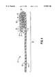
- FIG. 1is a cross-sectional view of a first embodiment of the laminated page
- FIG. 2is a plan view of a first embodiment of the laminated page
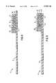
- FIG. 3is a cross-sectional view of a second embodiment of the laminated page
- FIG. 4is a cross-sectional view of a third embodiment of the laminated page
- FIG. 5is a cross-sectional view of a fourth embodiment of the laminated page
- FIG. 6is a plan view of a fifth embodiment of the laminated page
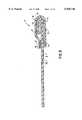
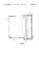
- FIG. 7is a perspective view of a sixth embodiment of the laminated page.
- FIG. 8is a cross-section of a seventh embodiment of the laminated page
- FIG. 9ais a plan view of the seventh embodiment of the laminated page in which the panels of the carrier sheet are open;
- FIG. 9bis a plan view of the seventh embodiment of the laminated page in which the panels of the carrier sheet are closed;
- FIG. 10is a schematic block diagram of a first method of making laminated pages.
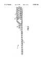
- FIG. 11is a perspective view of a continuous strip of laminated pages during the manufacturing process before folding and transverse cutting has taken place.
- FIGS. 1 and 2represent a laminated page according to the first embodiment of the present invention.
- the laminated page 1comprises sample material 6 deposited within a barrier ply 3 which is laminated to a carrier sheet 2.
- the laminated page 1 shown in FIGS. 1 and 2has a generally planar shape, but the laminated page of the present invention may be of various shapes.
- the barrier ply 3is laminated to the carrier sheet 2 by laminating adhesive 4.
- the carrier sheet 2is folded to form first panel 8 and second panel 8', which are two generally planar segments.
- Sample material 6is located in the sample area 5 located between first and second panels 8, 8'.
- Closure adhesive 7maintains the attachment between first and second panels 8, 8' until the laminated page 1 is opened by the user.
- the portion of the carrier sheet 2 from the closure adhesive 7 to the edge of the first panel 8forms lip 15, which the consumer may seize and pull.
- the lip 15may comprise part of the carrier sheet 2 and the barrier ply 3, as shown in FIG. 1.
- the lip 15may be an extension of carrier sheet 2 only, as in a second embodiment shown in FIG. 3, because it is not necessary for the barrier ply 3 to be flush with the edge of the carrier sheet 2.
- the lip 15may also comprise an extension of the barrier ply 3 only. The construction and shape of the lip 15 is unimportant, as long as it allows the user to detach the panels 8, 8'.
- FIG. 2shows a plan view of the laminated page 1 before it has been folded.
- Barrier ply 3is laminated to the full length of carrier sheet 2 with laminating adhesive 4 (not shown). As shown in FIG. 2, barrier ply 3 extends to three edges of the carrier sheet 2. Alternatively, the barrier ply 3 may be offset from any or all of the edges of the carrier sheet 2. The barrier ply may also be any shape. In another alternative embodiment, the barrier ply 3 may extend to all edges of the carrier sheet 2.
- Front surface 10 of the laminated page 1, as shown in FIGS. 1 and 2is a suitable area to display advertising text or artwork 12 encouraging the consumer to sample the sample material 6. As shown in FIG. 1, advertising text and artwork 12 also may cover the front surface 16 of first panel 8.
- advertising text or artworkmay be printed on both front surfaces 10, 16 such that when the laminated page 1 is folded as shown in FIG. 1, these surfaces 10, 16 may present a coordinated or continuous artwork or advertising message.
- Artwork or textmay also be printed on the surface of the carrier sheet 2 underneath the barrier ply 3, or on the barrier ply 3 itself, such that the artwork or text becomes visible to the user of the laminated page 1 when it is opened.
- Back surface 11, as shown in FIG. 1,is also suitable for displaying text and artwork. It is contemplated that when the laminated page 1 is bound into publications such as magazines or catalogs with advertising text or artwork printed on one or both sides, it will look substantially similar to pages of advertisement typically found in magazines.
- the carrier sheet 2is made of paper stock. Paper of varying grades and compositions, including recycled, colored, textured, coated, or uncoated, may be used. A wide variety of materials, other than paper stock, also may be used in the present invention. Because the barrier ply 3 substantially isolates the carrier sheet 2 from the sample material 6, problems of incompatibility between the carrier sheet 2 and the sample material 6 are eliminated by the present invention.
- the barrier ply 3is preferably made of a clear polyester film.
- the material used to form barrier ply 3should be substantially inert and impermeable to the contents of sample material 6 in order to substantially prevent migration of components of the sample material 6 through the barrier ply 3.
- Various types of plastic filmmay be used to form barrier ply 3 such as polyethylene terephtalate ("PET"), cellulosics or acetates.
- PETpolyethylene terephtalate
- a barrier materialmay be chosen which is a barrier to, for example, oil, gas, water vapor, aroma, or oxygen. The properties of these and other barriers are documented in publications, and they are readily available from commercial suppliers.
- the plastic filmmay be clear or opaque, oriented or non-oriented, coated or uncoated, metalized, laminated with other materials, reinforced, or filled.
- coated or laminated paper, or any other paper grades which may be more compatible with the sample material 6 than the carrier sheet 2may be used to form barrier ply 3.
- the barrier ply 3may also carry certain decorative features such as holographic images, embossing, hot stamping, and the like. It will be apparent to those skilled in the art that any material with appropriate properties may be used to form barrier ply 3.
- a material that does not possess barrier propertiesmay be coated or treated in order to give it barrier properties so that the material may be used to form barrier ply 3.
- barrier plymay also comprise a filled sheet.
- the fillermay impart opacity or texture to the surface of the barrier ply, or may contain antioxidants or other stabilizing components to protect the sample material.
- the choice of barrier ply materialdepends on factors such as cost, weight, ease of use, desired transparency or opaqueness, and suitability for displaying printed text and artwork (see discussion below regarding embodiments wherein the barrier ply is visible to the consumer). The material chosen can be pre-inspected and tested if desired to confirm that it provides the necessary barrier properties when used in combination with the sample material, carrier sheet, and adhesives selected for the laminated page.
- barrier ply 3may comprise more than one layer of material. Multiple layers may give the barrier ply 3 additional or improved properties or an enhanced appearance.
- An inner layer, which is in direct contact with sample material 6,may be chosen based on its compatibility with sample material 6.
- An outer layermay be selected to provide more secure lamination to carrier sheet 2. The layers of a multi-layered barrier ply 3 may be adhered together by many different methods which are known in the art.
- the thickness of the barrier ply 3may vary within a certain range. The bottom of the range is determined by the technology available to produce the barrier ply substantially without pin holes. The top of the range is determined by aesthetic considerations, the desired flatness of the entire laminated page, and cost.
- the preferred range of barrier ply thicknessis from around 10 microns to around 500 microns.
- the barrier ply 3is laminated to the carrier sheet 2 with the laminating adhesive 4 as shown in FIG. 1.
- adhesivesactivated by heat, moisture, pressure, drying or radiation curing may be suitable.
- Water-based latex adhesivesare preferable for lamination on paper because of their low cost and ease of application in-line on a print station. However, 100% solid adhesives such as hot-melt adhesive would be preferred for lamination of plastics.
- other attachment meansmay be used.
- the barrier ply 3may be heat laminated to the carrier sheet 2.
- the laminating adhesive 4covers the entire contact area between the carrier sheet 2 and the barrier ply 3.
- the laminating adhesive 4may be applied in a pattern of lines or dots, or just a few spots of adhesive may be used to keep the barrier ply 3 in place.
- the laminating adhesive 4may be permanent or it may be peelable, allowing the consumer to remove the barrier ply 3 to expose additional artwork or the like on the carrier sheet 2 beneath the barrier ply 3.
- a removable barrier ply 3may also facilitate use or application of the sample material 6 or allow the user to save some or all of the sample material 6 in the barrier ply 3 for later use.
- the carrier sheet 2may be perforated such that the user can remove the section or sections of the laminated page 1 containing the sample material from the rest of the magazine in which the laminated page 1 may be bound.
- a transparent material for the barrier ply 3 and laminating adhesive 4may be used if the advertiser wishes text or artwork beneath the barrier ply 3 to be visible to the consumer while using the laminated page 1.
- a laminating adhesive 4 cured by lightmay be desirable.
- special adhesivesmay be formulated to provide additional barrier properties.
- Such adhesivesmay contain agents such as oxygen scavengers or consist of film-forming precursors of high-barrier materials, such as latex-grade polyvinylidene chloride (PVdC).
- Sample material 6is preferably a fragrance or cosmetic.
- Cosmeticsinclude any external application intended to beautify or improve the complexion, skin, or hair. These include, for example, lipsticks, powders, foundations, mascaras, blushes, and eyeshadows.
- sample materialsmay be included in the present invention, such as personal care products, medical treatments, or even food samples.
- the sample material 6is a substantially unadulterated product such as a liquid perfume, in which case a barrier ply material may be selected in accordance with the method disclosed in U.S. Pat. No. 5,439,172 to Comyn et al.
- suitable barrier ply materials for use with a liquid fragrance sample materialare not limited to those disclosed in the Comyn et al. patent.
- Substantially unadulterated productsinclude any sample materials presented in their original or natural form, without being altered in any significant way.
- the sample materialcomprises a product which is presented in another form, such as in a gel form, in a powder form, in microcapsules, or contained in a matrix material.
- the sample material 6may comprise volatile and/or non-volatile components. It will be readily apparent to those in the art that many other sample materials are suitable for use with the present laminated page and method. In the embodiment shown FIGS. 1 and 2, the sample material 6 does not cover the entire sample area 5. However, in alternative embodiments, the sample material 6 may cover the entire sample area 5. Furthermore, a single laminated page may contain a plurality of different sample materials.
- the sample materialmay also contain a closure adhesive, in which case an additional closure adhesive 7 may not be necessary to keep the panels 8, 8' attached.
- a microencapsulated sample materialmay be mixed in an adhesive-containing slurry. If desired, the adhesive may be resealable, such that the laminated page may be re-closed.
- the closure adhesive 7is peelable. As shown in FIG. 2, the closure adhesive 7, together with the fold in the barrier ply 3, forms a continuous seal between first panel 8 and second panel 8' around sample material 6. A complete seal of the sample area 5 compartment is preferred in this embodiment because it limits the lateral migration of the sample material 6 or its components. Substantially impermeable seals are also preferred in order to limit alteration, decomposition or spoilage of the sample material from exposure to air and vapors.
- the sealmay be an adhesive seal, a heat-seal, or any other type of suitable seal.
- first panel 8 and second panel 8'may be attached together via heat sealing.
- first panel 8 and second panel 8'may be resealably attached so that the panels 8, 8' may be reattached after opening.
- a combination of sealsalso may be used. Whatever attaching means is used must withstand the rigors of shipping and handling so that the laminated page 1 does not accidentally open. However, the bond must be capable of quick and easy opening without significantly damaging the laminated page 1.
- closure adhesive 7also may vary in alternative embodiments. Some sample materials such as dry powders or encapsulated materials may not require an airtight seal. Therefore, a few spots of closure adhesive 7 may be applied to the barrier ply 3 in order to maintain the attachment between the opposing surfaces of the barrier ply 3. In such an embodiment, sample area 5 is not completely enclosed.
- the seal formed between the two opposing surfaces of the barrier ply 3 and around the sample material 6may be a permanent seal.
- Permanent sealsalso referred to as destruct or tear bonds, are also known in the art. Permanent seals also may be formed by adhesives or by heat sealing. If a permanent seal is used, it is advantageous to provide a means for opening the laminated page 1 to access the sample material 6, which likely will involve tearing the barrier ply 3. Such means are well known in the art and include a notch or a string to originate or facilitate the tear.
- closure adhesive 7it should be recognized that it is not necessary for the closure adhesive 7 to be positioned on the barrier ply 3 as shown in FIG. 1. As shown in FIG. 3, the closure adhesive 7 may be positioned on the carrier sheet 2 to keep the panels 8, 8' attached. Alternatively, the closure adhesive 7 may be positioned on the barrier ply 3 on one of the panels and/or the carrier sheet 2 on the other panel.
- the closure adhesive 7 pictured in FIGS. 1 and 2is not necessary.
- the barrier plyis made from a self-adhesive material which causes it to adhere to itself when its surfaces come into contact, or it is made from a film with a pre-manufactured, repositionable, pressure-sensitive adhesive layer, or a cohesively adhesive layer.
- the material used for the barrier plyis a material suitable for embossing.
- the border of the sample areacan be embossed, creating crimps.
- the crimpsmaintain contact between the opposing faces of barrier ply during trimming and normal shipping and handling without any additional adhesive material. When the consumer seizes and pulls the lip, the crimps yield, allowing access to the sample material.
- the embossingmay be done in such a way as to create a decorative pattern of artwork or advertising text on the outside surface of the laminated page while simultaneously fastening the panels around the sample area in the manner just described. Crimping or embossing may also be used in combination with adhesives or heat-sealing means.
- the carrier sheet 2is not folded. Therefore, only the barrier ply 3 is folded to enclose the sample material 6. Thus the barrier ply 3 is visible to the consumer viewing the laminated page 1.
- the barrier ply 3is made of an opaque material upon which artwork or advertisement is printed which, if desired, may be continuous with any artwork or advertisement printed on carrier sheet 2.
- the barrier ply 3, the laminating adhesive 4, and the sample material 6may be made of substantially transparent materials, allowing the consumer to see artwork or advertisements on the carrier sheet 2 underneath the layers of barrier ply 3.
- the laminating adhesive 4may be colored or opaque and arranged in a decorative pattern which the advertiser wishes the consumer to view through a transparent barrier ply 3 and transparent sample material 6.
- the material used for the barrier ply 3may be selected for its transparency to visible light or other types of radiation so that the closure adhesive 7 can be activated by irradiation through the barrier ply 3.
- the barrier ply 3may be made of a material upon which an ornamental design is embossed.
- the folded barrier ply 3need not be located at the edge of the carrier sheet 2, since it is folded independently of the carrier sheet 2. Thus, the barrier ply 3 may be located anywhere on the surface of the carrier sheet 2.
- the barrier ply 3may be oriented in any way on the carrier sheet 2.
- the barrier ply 3could be oriented such that lip 15 is located on the right-hand edge of the barrier ply 3 while the fold in the barrier ply 3 would be located on the left.
- the lip 15could be located at the top of the barrier ply with the fold located at the bottom, or the lip 15 could be located at the bottom of the barrier ply with the fold located at the top.
- the size and shape of the barrier plymay be altered in alternative embodiments. For instance, the barrier ply 3 can be reduced to the size of a small patch which is laminated to the carrier sheet 2.
- the embodiments described abovefeature a single barrier ply 3 which is folded to create a sample area 5.
- the sample area 5is bounded by two separate barrier plies 3 and 3', as shown in FIG. 5.
- Barrier ply 3'may be placed on top of sample material 6 and barrier ply 3 during the manufacturing process.
- the two barrier plies 3 and 3'may be formed from a single barrier ply which has been folded over as in previously described embodiments and then trimmed at the fold to divide the ply into two pieces. (See Detailed Description of the Method of Making the Laminated Page, below.)
- This two-barrier ply embodimentmay require additional closure adhesive 7' as shown in FIG. 5 to maintain secure attachment between the two barrier plies 3, 3'.
- Additional closure adhesive 7'may simply form a continuous peelable seal with closure adhesive 7 and comprise the same materials which compose closure adhesive 7.
- additional closure adhesive 7'may be a permanent bond which maintains a hinge between the two layers of the barrier ply 3 when the bond formed by the peelable closure adhesive 7 is broken to access the sample material 6.
- the laminated page of the present inventionmay include some features of samplers known in the art.
- the embodiment shown in FIG. 6incorporates a lift tab 21 for accessing the sample material 6.
- a portion of first panel 8is permanently attached to second panel 8' by permanent adhesive 23 and is not designed to be lifted by the consumer. Instead, lift tab 21 provides access to the sample material 6.
- Lift tab 21is positioned adjacent to sample area 5, and it is formed by die-cutting a line 20 through the carrier sheet 2 and the barrier ply 3 of the first panel 8.
- the line 20may form a continuous, closed shape, or may terminate in an open shape as shown in FIG. 6.
- Lift tab 21is held in place by peelable adhesive 22.
- line 20may be a perforated line or a die-cut line with notches or breaks.
- FIG. 6shows the laminated page before it has been folded, so that the areas of permanent and resealable adhesive can be seen clearly. In the finished laminated page, the first panel 8 is folded over and attached to second panel 8'.
- the permanent closure adhesive 23 and the resealable closure adhesive 22should be arranged so that the lift tab 21 does not come into contact with the permanent adhesive 23, which would prevent the consumer from lifting the lift tab 21. As shown in FIG. 6, there is an area where no adhesive 22 or 23 has been deposited to facilitate lifting of the lift tab 21. It will be readily apparent to those skilled in the art that more than one sample area may be defined between the opposing surfaces of the barrier ply 3. Each sample area may contain a different sample material, and each sample area may be accessed by a separate tab. The tabs may be located either on the first panel, the second panel, or both panels.
- FIG. 7A sixth embodiment is shown in FIG. 7.
- This laminated page 1maintains the same general structure and function as the previously discussed embodiments, but there is a closed die-cut line 20 in the carrier sheet 2 which defines a display aperture 30 where the carrier sheet 2 has been omitted or removed.
- This aperture 30does not pass through the barrier ply (omitted from FIG. 7 for clarity), which remains intact.
- the barrier plyis transparent, and aperture 30 allows the consumer to view the sample material 6 without having to open the device 1. Allowing consumers to view sample materials may encourage them to try the sample material, particularly colored cosmetics.
- multiple viewing aperturescan be provided at different locations above the sample area 5. For example, a second viewing aperture can be provided on the back surface (not shown in FIG.
- the portion of the carrier sheet 2 defined by the perforated or die-cut line 20may be left in place, which allows the consumer to lift the portion to view the sample material 6 before opening the laminated page 1. It will be readily apparent to those skilled in the art that a plurality of die-cut lines may be incorporated in this embodiment to provide a plurality of viewing apertures and/or liftable portions.
- the present inventionalso includes embodiments in which a barrier ply is laminated to the outside of the panels of the carrier sheet in order to seal in the sample material and the portion of the carrier sheet in contact with the sample material.
- a barrier plyis laminated to the outside of the panels of the carrier sheet in order to seal in the sample material and the portion of the carrier sheet in contact with the sample material.
- the sample material 6(omitted from FIG. 9b for clarity) is enclosed between two panels of the carrier sheet 2, and the barrier ply 3 is laminated to the outside of the carrier sheet 2 by lines of adhesive 4.
- Opposing faces of the barrier ply 3are attached together beyond the top and bottom of the carrier sheet 2, as shown in FIG. 9b.
- FIG. 9ashows a laminated page before closure
- FIGS. 8 and 9bshow a device which has been closed.
- this embodimentnonetheless provides the benefit of substantial protection from migration of the sample material 6 out of the laminated page 1 since the sample material 6 is covered by the barrier ply 3.
- opposing surfaces near or at the top and bottom edges of the barrier ply 3are attached together by a line of adhesive 4.
- Any appropriate type of adhesivemay be used.
- the barrier ply 3may be heat laminated to the carrier sheet 2, and the opposing surfaces at the top and bottom edges of the barrier ply 3 may be heat-sealed together by trimming the edges with a hot knife.
- Alternative attachment means, such as are described above,may be used.
- the barrier ply material at the top and bottom edgesmay be folded in order to effect a seal.
- the barrier ply 3may be completely sealed across the top and bottom of the carrier sheet 2, when a complete seal is not required, spots of adhesive may be applied at the top and bottom edges of the barrier ply 3 to attach the barrier ply 3 to itself beyond the top and bottom edges of the carrier sheet 2. Furthermore, the barrier ply 3 may also extend beyond the right or left-hand edges of the laminated page 1. In such cases, the opposing faces of the barrier ply 3 may be attached together as described for the top and bottom extending portions of barrier ply 3 shown in FIGS. 9a and 9b.
- the barrierneed not be formed from a continuous sheet of material as shown in FIGS. 8-9b.
- the barriercould be formed from two or more discontinuous barrier plies enclosing the sample material 6 and carrier sheet 2.
- the carrier sheet 2could also be formed from two or more discontinuous portions.
- the barrier ply 3does not extend beyond the top and bottom edges of the carrier sheet 2. Edges of the barrier ply 3 may be flush with the top edge, the bottom edge or both edges of the carrier sheet 2. Alternatively, the barrier ply 3 may not extend fully to the top edge, the bottom edge, or either the top or bottom edge of the carrier sheet 2.
- Heat or ultraviolet lamination or any alternative means of attachmentmay be used to laminate the barrier ply 3 to the carrier sheet 2.
- the portion of the laminated page 1 containing the sample material 6can be removed from the remainder of the laminated page 1, in a sealed enclosure, by tearing the line of perforations 70. Then lip 15 can be seized and lifted, releasing the sample material 6 as in previous embodiments.
- This line of perforations 70may be incorporated into any of the above-mentioned embodiments to allow a section of the laminated page 1 containing the sample material 6 to be removed from the remainder of the laminated page 1.
- the shape of the line of perforations 70may be altered in alternative embodiments.
- the lip 15may be extended and attached to the carrier sheet 2 on the opposite side of the line of perforations 70. In such cases, the lip 15 will be held in place until the line of perforations 70 is torn, thereby detaching the lip 15 from the carrier sheet 2 and allowing the user to open the laminated page 1.
- barrier ply 3 and the carrier sheet 2are not limited to the relative dimensions shown in FIGS. 8-9b.
- the barrier ply 3could be the size of a magazine page, while the laminated portion of the carrier sheet 2 could be smaller than the barrier ply 3.
- the sample material 6contacts the carrier sheet 2. Therefore, the carrier sheet 2 must be made of a material that will not affect, degrade or contaminate the sample material 6.
- the preferred sample materialcomprises a fragrance.
- other types of sample materialalso may be included in this embodiment.
- the method of making laminated pages according to the present inventionis a continuous process which yields a large number of laminated pages easily and at high speed, and yields laminated pages with substantially reliable protection from premature exposure, leakage, or pre-release and from undesirable interaction between the sample material and the carrier sheet.
- the preferred methodshown schematically in FIG. 10, comprises a multi-stream, single-pass printing process with on-press lamination of barrier ply material which is slit in-line into multiple streams.
- FIG. 11shows a section of a continuous stream of laminated pages 1 during the manufacturing process before transverse cutting has occurred.
- several substantially parallel streams of laminated pagesmay be passed through the printing process simultaneously to increase the number of laminated pages produced.
- a single stream of laminated pagesmay be manufactured using the method of the present invention.
- a carrier sheet 2is advanced from the supply roll 40 into the printing apparatus 42. After advertising text and/or artwork 12 is printed on the carrier sheet 2, the ink is dried, if necessary, by drier 43. Laminating adhesive (omitted from FIG. 11 for clarity) is applied at applicator 44.
- Barrier ply materialis introduced to the process in multiple ribbons.
- the barrier ply materialis slit, in-line, into ribbons of appropriate width at slitting station 60.
- the ribbonsare separated into individual barrier plies 3 and 3' by ribbon deck 61, which controls the spacing between the ribbons using turn bars 62. Only two ribbons of barrier ply 3, 3' are shown in FIG. 10. However, several ribbons of laminating barrier ply material may be provided by the ribbon deck 61 to allow multiple, parallel streams of laminated pages to be manufactured simultaneously.
- the barrier plies 3, 3'are positioned onto the carrier sheet 2.
- the barrier plies 3, 3'are then laminated to the carrier sheet 2 at the nip of pressure roller 45, which activates the adhesive force of the laminating adhesive.
- Closure adhesive 7is next applied by applicator 46.
- the position of the closure adhesive 7will be determined by the type of attachment desired between the two panels of the laminated page 1 which are formed when the streams of laminated pages are folded.
- the closure adhesivemay be positioned such that, after the laminated page is folded (see below), there will be attachment between the two opposing faces of the barrier ply 3 (as shown in FIG. 11), between the two opposing faces of the carrier sheet 2, or between one of the faces of the barrier ply 3 and the opposing carrier sheet 2. In the latter case, the size of the barrier ply 3 must be adjusted such that a portion of the barrier ply surface may be attached to the an opposing carrier sheet surface.
- the sample material 6is deposited by applicator 47.
- the carrier sheet 2then passes through longitudinal slitting station 51, which slits the carrier sheet 2 into a plurality of streams of laminated pages.
- the streams of laminated pagesnext pass through folder 52, which folds the devices along fold line 55 (shown in FIG. 11), enclosing the sample material 6 between two panels, the panels comprising layers of the barrier ply 3 and carrier sheet 2.
- the closure adhesive 7maintains the laminated pages in the closed position.
- the continuous streams of laminated pagesare cut along transverse cutting lines 56 by transverse cutter 49. Individual laminated pages 1 are then packed at packing station 50.
- laminating station 45comprises a pressure roller in the above-described embodiment, the laminating station may comprise other appropriate laminating means depending on the type of bonding between the barrier ply and the carrier sheet.
- the above-described processmay contain fewer steps or additional steps, depending on the materials used and characteristics desired. For instance, choosing a self-adhesive material for the barrier ply 3 may eliminate the need for applicator 44. Alternatively, if a multi-layered barrier ply 3 is desired, the slitter 60 and ribbon deck 61 may be used to create additional ribbons of material which may be stacked to create a multi-layered barrier ply 3. In the case of full-page lamination, the barrier ply 3 is laminated to the carrier sheet in one continuous stream. Additional adhesive applicators and laminating stations may also be added to fasten the multiple layers together.
- An alternative embodiment of the present methodmay be used to make the laminated page as pictured in FIG. 5.
- the devicesare not folded, but instead the sample material is enclosed between two separate barrier plies.
- the barrier plies 3, 3'comprise two separate ribbons.
- the first barrier ply ribbonis laminated to the carrier sheet, the sample material and closure adhesive are applied, and then the second barrier ply ribbon is applied over the sample area.
- the sample material 6is thus completely covered as shown in FIG. 5.
- the laminated pagesare then cut and packed as in other embodiments.
- Another method of making the laminated pageinvolves laminating part of the barrier ply 3 to the carrier sheet 2, applying the sample material 6 and the closure adhesive 7 to the barrier ply 3, and then folding the barrier ply 3, but not the carrier sheet 2, to enclose the sample material 6 within the barrier ply 3, as pictured in FIG. 4.
- Yet another method of making laminated pagesinvolves folding a single barrier ply 3 to close the sample area 5 and then trimming the fold itself from the laminated page, thereby dividing the barrier ply 3 into two pieces, 3 and 3', as shown in FIG. 5.
- Sufficient additional closure adhesive 7'must be applied in order to maintain a secure attachment between barrier plies 3, 3' and avoid pre-release of sample material 6. If additional closure adhesive 7' comprises the same material as closure adhesive 7, one applicator 46 may be sufficient to apply both as shown in FIG. 10. However, if two different adhesive means are employed, an additional applicator may be necessary.
- a dieis employed to cut and remove a portion of the carrier sheet 2 in order to create the display aperture 30. This step may be done at any point in the process of creating the laminated pages. However, this step is preferably performed before the sample material is deposited.
- a dieis employed to cut the lift tab 21 in the carrier sheet 2, the laminating adhesive and the barrier ply 3.
- separate applicatorsmay be used to apply the permanent and resealable adhesives 23 and 22. As shown in FIG. 6, the lift tab should not come into contact with the permanent adhesive 23, as that would prevent the tab from being lifted.
- methods used to create embodiments involving embossed barrier plies described aboverequire an embosser in the assembly process rather than a closure adhesive applicator.
- the order in which the steps are performedmay be altered in certain cases.
- the sample material 6could be deposited before, or contemporaneously with, the closure adhesive 7 without altering the utility of the method.
- the order in which the steps of the method are performedis not critical, as long as the continuity of the process is maintained.
- individual laminated pageswould be separated from a large sheet by die-cutting, rather than by longitudinal slitting and transverse cutting. This would allow manufacturing of laminated pages having circular or other attractive shapes, instead of being limited to rectangular shapes.
- FIGS. 8-9bAnother alternative embodiment of the method is used to make laminated pages as pictured in FIGS. 8-9b.
- the sample materialis deposited on the carrier sheet 2, rather than the barrier ply 3. Longitudinal and transverse cutting of the carrier sheet 2 may be done before the barrier ply 3 is attached, to allow construction of laminated pages in which the barrier ply 3 extends beyond the top and bottom edges of the carrier sheet 2, as shown in FIGS. 9a and 9b.
Landscapes
- Physics & Mathematics (AREA)
- General Physics & Mathematics (AREA)
- Engineering & Computer Science (AREA)
- Theoretical Computer Science (AREA)
- Laminated Bodies (AREA)
- Joining Of Glass To Other Materials (AREA)
- Wrappers (AREA)
Abstract
Description
Claims (19)
Priority Applications (8)
| Application Number | Priority Date | Filing Date | Title |
|---|---|---|---|
| US08/791,875US5928748A (en) | 1997-01-31 | 1997-01-31 | Laminated page and method for making same |
| EP98906050AEP1012061B1 (en) | 1997-01-31 | 1998-01-30 | Laminated page and method for making same |
| PCT/US1998/001773WO1998033721A1 (en) | 1997-01-31 | 1998-01-30 | Laminated page and method for making same |
| AT98906050TATE263673T1 (en) | 1997-01-31 | 1998-01-30 | LAMINATED FILM AND PRODUCTION PROCESS |
| CA002279364ACA2279364C (en) | 1997-01-31 | 1998-01-30 | Laminated page and method for making same |
| AU61381/98AAU6138198A (en) | 1997-01-31 | 1998-01-30 | Laminated page and method for making same |
| DE69823043TDE69823043T2 (en) | 1997-01-31 | 1998-01-30 | LAMINATED FOIL AND MANUFACTURING METHOD |
| US09/209,816US6125614A (en) | 1997-01-31 | 1998-12-11 | Method for making laminated page |
Applications Claiming Priority (1)
| Application Number | Priority Date | Filing Date | Title |
|---|---|---|---|
| US08/791,875US5928748A (en) | 1997-01-31 | 1997-01-31 | Laminated page and method for making same |
Related Child Applications (1)
| Application Number | Title | Priority Date | Filing Date |
|---|---|---|---|
| US09/209,816DivisionUS6125614A (en) | 1997-01-31 | 1998-12-11 | Method for making laminated page |
Publications (1)
| Publication Number | Publication Date |
|---|---|
| US5928748Atrue US5928748A (en) | 1999-07-27 |
Family
ID=25155054
Family Applications (2)
| Application Number | Title | Priority Date | Filing Date |
|---|---|---|---|
| US08/791,875Expired - LifetimeUS5928748A (en) | 1997-01-31 | 1997-01-31 | Laminated page and method for making same |
| US09/209,816Expired - LifetimeUS6125614A (en) | 1997-01-31 | 1998-12-11 | Method for making laminated page |
Family Applications After (1)
| Application Number | Title | Priority Date | Filing Date |
|---|---|---|---|
| US09/209,816Expired - LifetimeUS6125614A (en) | 1997-01-31 | 1998-12-11 | Method for making laminated page |
Country Status (7)
| Country | Link |
|---|---|
| US (2) | US5928748A (en) |
| EP (1) | EP1012061B1 (en) |
| AT (1) | ATE263673T1 (en) |
| AU (1) | AU6138198A (en) |
| CA (1) | CA2279364C (en) |
| DE (1) | DE69823043T2 (en) |
| WO (1) | WO1998033721A1 (en) |
Cited By (24)
| Publication number | Priority date | Publication date | Assignee | Title |
|---|---|---|---|---|
| US6182572B1 (en)* | 1998-08-29 | 2001-02-06 | Malessa Partners, L.L.C. | Method and apparatus for producing multiple cut business forms |
| US6403186B1 (en) | 1998-02-10 | 2002-06-11 | Aki, Inc. | Product sampler |
| FR2824291A1 (en)* | 2001-05-07 | 2002-11-08 | Wallon Imprimeur | METHOD FOR MANUFACTURING AN ARTICLE COMPRISING A HOUSING CONTAINING A DISSOCIABLE TAB OF ITS HOUSING BY A TRACTION AND ARTICLE THUS MANUFACTURED |
| US6503625B1 (en) | 1999-10-08 | 2003-01-07 | W.R. Grace & Co. - Conn. | Fibers for reinforcing matrix materials |
| US20030186014A1 (en)* | 1999-10-13 | 2003-10-02 | Malessa Partners L.L.C. | Integrated forms and method of making such forms |
| US6629705B1 (en) | 2001-06-20 | 2003-10-07 | Gary R. Ellis | Magazine insert and method for making same |
| US6686013B1 (en)* | 1999-08-10 | 2004-02-03 | Deotexis Inc. | Article comprising board, paper or the like and process and intermediate product for the production thereof |
| US20060263579A1 (en)* | 2004-06-04 | 2006-11-23 | Perfect Scents Of Illinois, Llc. | Advertising page containing micro-encapsulated material |
| US20080241453A1 (en)* | 2007-03-26 | 2008-10-02 | Akins Gary L | Fragrance advertising assembly |
| US20100108778A1 (en)* | 2008-10-30 | 2010-05-06 | Greenland Steven J | Device for containing and releasing a volatile substance |
| US20100163447A1 (en)* | 2008-12-31 | 2010-07-01 | Greenland Steven J | Device for containing and releasing a sample material |
| US20100323134A1 (en)* | 2009-06-23 | 2010-12-23 | Appleton Papers Inc. | Laminate with Aroma Burst |
| US20110042256A1 (en)* | 2009-08-24 | 2011-02-24 | Greenland Steven J | Unitized package and method of making same |
| US20110108632A1 (en)* | 2009-11-12 | 2011-05-12 | Hayloft Enterprises, Inc. | Air freshener vent clip and accessory |
| US20110259512A1 (en)* | 2008-04-25 | 2011-10-27 | Amcor Flexibles Transpac N.V. | Method for the Production of Thin Polymer Film |
| US20110274921A1 (en)* | 2010-05-05 | 2011-11-10 | Ford Global Technologies, Llc | Trim component and method of edge folding |
| US20120025511A1 (en)* | 2010-07-30 | 2012-02-02 | Samplemax Inc. | Apparatus for Distributing Samples |
| US20150063895A1 (en)* | 2013-09-03 | 2015-03-05 | Sven Dobler | Fragrance sampler having an integral applicator |
| US9272830B2 (en) | 2009-08-24 | 2016-03-01 | Aki, Inc. | Unitized package of card and fluid vessel |
| US20160133166A1 (en)* | 2014-11-07 | 2016-05-12 | Per Dobler | Removable fragrance sampler |
| US10066046B2 (en)* | 2010-01-14 | 2018-09-04 | Henkel Ag & Co. Kgaa | One-component laminating adhesive having silane cross-linking |
| US20200062465A1 (en)* | 2018-08-21 | 2020-02-27 | Illinois Tool Works Inc. | Fold and seal flexible valves |
| US11535439B2 (en)* | 2019-10-18 | 2022-12-27 | Sonoco Development, Inc. | Pasteurization pouch with barrier |
| US11896744B2 (en) | 2015-06-11 | 2024-02-13 | Zobele Holding S.P.A. | Cartridge with vapour permeable membrane, in particular for volatile substances such as insecticides and fragrances |
Families Citing this family (18)
| Publication number | Priority date | Publication date | Assignee | Title |
|---|---|---|---|---|
| US20090250530A1 (en)* | 2008-04-04 | 2009-10-08 | Blaine Stambaugh | Product for liquid delivery fragrance samples |
| US9150342B2 (en) | 2003-04-16 | 2015-10-06 | Intercontinental Great Brands Llc | Resealable tray container |
| US6929128B2 (en)* | 2003-06-12 | 2005-08-16 | Marietta Corporation | Product sampler packet assembly with enhanced burst strength and method of manufacture |
| US7281360B1 (en)* | 2005-02-11 | 2007-10-16 | Bryce Corporation | Thermal laminates and laminating method of food packaging films |
| US8308363B2 (en) | 2006-05-23 | 2012-11-13 | Kraft Foods Global Brands Llc | Package integrity indicator for container closure |
| US7963413B2 (en) | 2006-05-23 | 2011-06-21 | Kraft Foods Global Brands Llc | Tamper evident resealable closure |
| US20080041755A1 (en)* | 2006-08-18 | 2008-02-21 | Kristine Gail Noschang | Package assembly with product feature display area |
| US8114451B2 (en) | 2006-12-27 | 2012-02-14 | Kraft Foods Global Brands Llc | Resealable closure with package integrity feature |
| US8408792B2 (en) | 2007-03-30 | 2013-04-02 | Kraft Foods Global Brands Llc | Package integrity indicating closure |
| US20100018974A1 (en) | 2008-07-24 | 2010-01-28 | Deborah Lyzenga | Package integrity indicating closure |
| GB0819200D0 (en) | 2008-10-20 | 2008-11-26 | Cadbury Holdings Ltd | Packaging |
| ES2390202T3 (en) | 2010-01-26 | 2012-11-07 | Generale Biscuit | Resealable container for food products and manufacturing process |
| PL2368811T3 (en) | 2010-03-23 | 2012-11-30 | Biscuit Gle | Resealable packaging for food products and method of manufacturing |
| WO2011146658A1 (en) | 2010-05-18 | 2011-11-24 | Kraft Foods Global Brands Llc | Reclosable flexible packaging and methods for manufacturing same |
| US9656783B2 (en) | 2010-05-18 | 2017-05-23 | Intercontinental Great Brands Llc | Reclosable flexible packaging and methods for manufacturing same |
| BR112013023727B1 (en) | 2011-03-17 | 2020-12-22 | Intercontinental Great Brands Llc | resealable flexible film packaging, laminated to form a resealable flexible film packaging, method for forming a resealable flexible film packaging laminate and apparatus for forming resealable flexible film packaging |
| FR2975268B1 (en)* | 2011-05-20 | 2014-01-24 | Dreux | MULTILAYER COMPOSITE FOR DIFFUSION OF ODORANT SUBSTANCES AND METHOD OF MANUFACTURE |
| GB2615636A (en)* | 2021-12-15 | 2023-08-16 | Adhespack Ind Comercio Importacao E Exportacao Ltda | Aroma-releasing bilaminate self-adhesive label |
Citations (29)
| Publication number | Priority date | Publication date | Assignee | Title |
|---|---|---|---|---|
| US3116077A (en)* | 1962-09-05 | 1963-12-31 | Bird Ruth | Advertising devices incorporating a dispensable aroma |
| US3718277A (en)* | 1971-08-24 | 1973-02-27 | J Volkert | Printed folder including mailable article |
| US3998684A (en)* | 1976-01-12 | 1976-12-21 | Mcright Kenneth L | Method of manufacturing air cushions |
| US4083451A (en)* | 1972-09-14 | 1978-04-11 | Hair George R | Method of heat sealing sheet-form layers of perforated plastic between layers of paperboard |
| US4313557A (en)* | 1980-05-14 | 1982-02-02 | Berlin Industries, Inc. | Envelope insert for magazines |
| US4484768A (en)* | 1983-09-30 | 1984-11-27 | Norfleet Lincoln H | Greeting card |
| US4612223A (en)* | 1985-05-20 | 1986-09-16 | Donald Spector | Reversible fragrance emitting unit |
| EP0268316A1 (en)* | 1986-10-27 | 1988-05-25 | Jos. Hunkeler AG Fabrik für graphische Maschinen | A method of making a strippable material containing odorant, and intermediate product produced by applying part of said method |
| US4752496A (en)* | 1986-05-27 | 1988-06-21 | Qmax Technology Group, Inc. | Method of applying cosmetics to a substrate and article |
| US4824707A (en)* | 1988-06-27 | 1989-04-25 | Donald Spector | Decorative air freshener unit |
| US4923063A (en)* | 1988-11-03 | 1990-05-08 | Webcraft Technologies, Inc. | Sample packet for creams and method of manufacture |
| US4941574A (en)* | 1989-08-11 | 1990-07-17 | Frank Meehan | Package for a liquid sample and an associated method for packaging a liquid sample |
| US4998621A (en)* | 1989-08-11 | 1991-03-12 | Frank Meehan | Package for a liquid sample and an associated method for packaging a liquid sample |
| US5161688A (en)* | 1988-04-22 | 1992-11-10 | Muchin Jerome D | Sampler and method of making the same |
| US5188236A (en)* | 1990-11-21 | 1993-02-23 | Herbert M. Sayers | Scent sampler construction |
| US5242521A (en)* | 1991-09-25 | 1993-09-07 | The Lehigh Press, Inc. | Method of making a controllable fragrance sampler |
| US5248537A (en)* | 1992-07-22 | 1993-09-28 | Danbury Printing & Litho, Inc. | Non-contaminating fragrance releasing insert for magazines |
| US5268214A (en)* | 1991-09-04 | 1993-12-07 | Minnesota Mining And Manufacturing | Fragrance sampler with protective treatment |
| US5268209A (en)* | 1989-12-21 | 1993-12-07 | Alza Corporation | Nicotine packaging materials |
| WO1994005182A1 (en)* | 1992-09-09 | 1994-03-17 | Alexandre Vanbraekel | Sampling device for perfume |
| US5337897A (en)* | 1990-05-21 | 1994-08-16 | Gerald Yablans | Sampler cartridge display case and unit sampler |
| US5391420A (en)* | 1991-07-16 | 1995-02-21 | Thermedics Inc. | Fragrance-laden pouch samplers and process for their manufacture |
| US5419958A (en)* | 1992-05-28 | 1995-05-30 | Minnesota Mining And Manufacturing Company | Reduced odor fragrance sampler |
| US5439172A (en)* | 1992-07-29 | 1995-08-08 | The Beautiful Bouquet Company Limited | Planar sampler for a liquid volatile material and method |
| US5534105A (en)* | 1993-04-12 | 1996-07-09 | Boyd; Craig A. | Method and apparatus for sealing applied scent slurry during the printing process |
| WO1996034808A1 (en)* | 1995-05-04 | 1996-11-07 | Jos. Hunkeler Ag Papierverarbeitungsmaschinen | Process for producing products secured to a substrate, like packed samples, credit and identity cards ant the like |
| US5622263A (en)* | 1995-05-01 | 1997-04-22 | Webcraft Technologies, Inc. | Sampler package and method of making the same |
| US5645161A (en)* | 1996-01-22 | 1997-07-08 | Orlandi Inc. | Fragrance packet sampler |
| US5715849A (en)* | 1992-09-09 | 1998-02-10 | Vanbraekel; Alexandre | Perfume sampler |
Family Cites Families (3)
| Publication number | Priority date | Publication date | Assignee | Title |
|---|---|---|---|---|
| US4876136A (en)* | 1987-06-22 | 1989-10-24 | Minnesota Mining And Manufacturing Company | Lipstick sampling device |
| WO1992014607A1 (en)* | 1991-02-19 | 1992-09-03 | Carnahan David W | Fragrance sampler with dual fragrance delivery means |
| US5637401A (en)* | 1994-06-08 | 1997-06-10 | Fragrance Technology Trust | Odorant composition, delivery system and method |
- 1997
- 1997-01-31USUS08/791,875patent/US5928748A/ennot_activeExpired - Lifetime
- 1998
- 1998-01-30EPEP98906050Apatent/EP1012061B1/ennot_activeExpired - Lifetime
- 1998-01-30DEDE69823043Tpatent/DE69823043T2/ennot_activeExpired - Lifetime
- 1998-01-30CACA002279364Apatent/CA2279364C/ennot_activeExpired - Fee Related
- 1998-01-30WOPCT/US1998/001773patent/WO1998033721A1/enactiveIP Right Grant
- 1998-01-30AUAU61381/98Apatent/AU6138198A/ennot_activeAbandoned
- 1998-01-30ATAT98906050Tpatent/ATE263673T1/ennot_activeIP Right Cessation
- 1998-12-11USUS09/209,816patent/US6125614A/ennot_activeExpired - Lifetime
Patent Citations (30)
| Publication number | Priority date | Publication date | Assignee | Title |
|---|---|---|---|---|
| US3116077A (en)* | 1962-09-05 | 1963-12-31 | Bird Ruth | Advertising devices incorporating a dispensable aroma |
| US3718277A (en)* | 1971-08-24 | 1973-02-27 | J Volkert | Printed folder including mailable article |
| US4083451A (en)* | 1972-09-14 | 1978-04-11 | Hair George R | Method of heat sealing sheet-form layers of perforated plastic between layers of paperboard |
| US3998684A (en)* | 1976-01-12 | 1976-12-21 | Mcright Kenneth L | Method of manufacturing air cushions |
| US4313557A (en)* | 1980-05-14 | 1982-02-02 | Berlin Industries, Inc. | Envelope insert for magazines |
| US4484768A (en)* | 1983-09-30 | 1984-11-27 | Norfleet Lincoln H | Greeting card |
| US4612223A (en)* | 1985-05-20 | 1986-09-16 | Donald Spector | Reversible fragrance emitting unit |
| US4752496A (en)* | 1986-05-27 | 1988-06-21 | Qmax Technology Group, Inc. | Method of applying cosmetics to a substrate and article |
| EP0268316A1 (en)* | 1986-10-27 | 1988-05-25 | Jos. Hunkeler AG Fabrik für graphische Maschinen | A method of making a strippable material containing odorant, and intermediate product produced by applying part of said method |
| US5161688A (en)* | 1988-04-22 | 1992-11-10 | Muchin Jerome D | Sampler and method of making the same |
| US4824707A (en)* | 1988-06-27 | 1989-04-25 | Donald Spector | Decorative air freshener unit |
| US4923063A (en)* | 1988-11-03 | 1990-05-08 | Webcraft Technologies, Inc. | Sample packet for creams and method of manufacture |
| US4941574A (en)* | 1989-08-11 | 1990-07-17 | Frank Meehan | Package for a liquid sample and an associated method for packaging a liquid sample |
| US4998621A (en)* | 1989-08-11 | 1991-03-12 | Frank Meehan | Package for a liquid sample and an associated method for packaging a liquid sample |
| US5268209A (en)* | 1989-12-21 | 1993-12-07 | Alza Corporation | Nicotine packaging materials |
| US5337897A (en)* | 1990-05-21 | 1994-08-16 | Gerald Yablans | Sampler cartridge display case and unit sampler |
| US5188236A (en)* | 1990-11-21 | 1993-02-23 | Herbert M. Sayers | Scent sampler construction |
| US5391420A (en)* | 1991-07-16 | 1995-02-21 | Thermedics Inc. | Fragrance-laden pouch samplers and process for their manufacture |
| US5268214A (en)* | 1991-09-04 | 1993-12-07 | Minnesota Mining And Manufacturing | Fragrance sampler with protective treatment |
| US5389174A (en)* | 1991-09-25 | 1995-02-14 | The Lehigh Press, Inc. | Method of making a controllable fragrance sampler |
| US5242521A (en)* | 1991-09-25 | 1993-09-07 | The Lehigh Press, Inc. | Method of making a controllable fragrance sampler |
| US5419958A (en)* | 1992-05-28 | 1995-05-30 | Minnesota Mining And Manufacturing Company | Reduced odor fragrance sampler |
| US5248537A (en)* | 1992-07-22 | 1993-09-28 | Danbury Printing & Litho, Inc. | Non-contaminating fragrance releasing insert for magazines |
| US5439172A (en)* | 1992-07-29 | 1995-08-08 | The Beautiful Bouquet Company Limited | Planar sampler for a liquid volatile material and method |
| WO1994005182A1 (en)* | 1992-09-09 | 1994-03-17 | Alexandre Vanbraekel | Sampling device for perfume |
| US5715849A (en)* | 1992-09-09 | 1998-02-10 | Vanbraekel; Alexandre | Perfume sampler |
| US5534105A (en)* | 1993-04-12 | 1996-07-09 | Boyd; Craig A. | Method and apparatus for sealing applied scent slurry during the printing process |
| US5622263A (en)* | 1995-05-01 | 1997-04-22 | Webcraft Technologies, Inc. | Sampler package and method of making the same |
| WO1996034808A1 (en)* | 1995-05-04 | 1996-11-07 | Jos. Hunkeler Ag Papierverarbeitungsmaschinen | Process for producing products secured to a substrate, like packed samples, credit and identity cards ant the like |
| US5645161A (en)* | 1996-01-22 | 1997-07-08 | Orlandi Inc. | Fragrance packet sampler |
Cited By (38)
| Publication number | Priority date | Publication date | Assignee | Title |
|---|---|---|---|---|
| US6726797B2 (en) | 1998-02-10 | 2004-04-27 | Aki, Inc. | Method of making product sampler |
| US6403186B1 (en) | 1998-02-10 | 2002-06-11 | Aki, Inc. | Product sampler |
| US6389971B1 (en) | 1998-08-29 | 2002-05-21 | Malessa Partners, Llc | Method and apparatus for producing business forms |
| US6182572B1 (en)* | 1998-08-29 | 2001-02-06 | Malessa Partners, L.L.C. | Method and apparatus for producing multiple cut business forms |
| US6986306B2 (en) | 1998-08-29 | 2006-01-17 | Malessa Partners, L.L.C. | Method and apparatus for producing multiple die-cut business forms |
| US6686013B1 (en)* | 1999-08-10 | 2004-02-03 | Deotexis Inc. | Article comprising board, paper or the like and process and intermediate product for the production thereof |
| US6503625B1 (en) | 1999-10-08 | 2003-01-07 | W.R. Grace & Co. - Conn. | Fibers for reinforcing matrix materials |
| US6989183B2 (en) | 1999-10-13 | 2006-01-24 | Malessa Partners, L.L.C. | Integrated forms and method of making such forms |
| US20030186014A1 (en)* | 1999-10-13 | 2003-10-02 | Malessa Partners L.L.C. | Integrated forms and method of making such forms |
| US20040166276A1 (en)* | 2001-05-07 | 2004-08-26 | Wallon Imprimeur Sa. | Promotional article, such as for advertising, product sampling or information supplying, and method of manufacturing same |
| WO2002090124A1 (en)* | 2001-05-07 | 2002-11-14 | Wallon Imprimeur Sa | Method for making an article comprising a housing containing a tab detachable from its housing by pulling and resulting article |
| FR2824291A1 (en)* | 2001-05-07 | 2002-11-08 | Wallon Imprimeur | METHOD FOR MANUFACTURING AN ARTICLE COMPRISING A HOUSING CONTAINING A DISSOCIABLE TAB OF ITS HOUSING BY A TRACTION AND ARTICLE THUS MANUFACTURED |
| US6629705B1 (en) | 2001-06-20 | 2003-10-07 | Gary R. Ellis | Magazine insert and method for making same |
| US20060263579A1 (en)* | 2004-06-04 | 2006-11-23 | Perfect Scents Of Illinois, Llc. | Advertising page containing micro-encapsulated material |
| US20080241453A1 (en)* | 2007-03-26 | 2008-10-02 | Akins Gary L | Fragrance advertising assembly |
| US20110259512A1 (en)* | 2008-04-25 | 2011-10-27 | Amcor Flexibles Transpac N.V. | Method for the Production of Thin Polymer Film |
| US20100108778A1 (en)* | 2008-10-30 | 2010-05-06 | Greenland Steven J | Device for containing and releasing a volatile substance |
| US20100163447A1 (en)* | 2008-12-31 | 2010-07-01 | Greenland Steven J | Device for containing and releasing a sample material |
| US8763805B2 (en) | 2008-12-31 | 2014-07-01 | Aki, Inc. | Device for containing and releasing a sample material |
| US20100323134A1 (en)* | 2009-06-23 | 2010-12-23 | Appleton Papers Inc. | Laminate with Aroma Burst |
| US20110042256A1 (en)* | 2009-08-24 | 2011-02-24 | Greenland Steven J | Unitized package and method of making same |
| US9272830B2 (en) | 2009-08-24 | 2016-03-01 | Aki, Inc. | Unitized package of card and fluid vessel |
| US9469435B2 (en) | 2009-08-24 | 2016-10-18 | Aki, Inc. | Unitized package and method of making same |
| US8578684B2 (en) | 2009-08-24 | 2013-11-12 | Aki, Inc. | Unitized package and method of making same |
| US8739973B2 (en) | 2009-08-24 | 2014-06-03 | Aki, Inc. | Unitized package of card and fluid vessel |
| US20110108632A1 (en)* | 2009-11-12 | 2011-05-12 | Hayloft Enterprises, Inc. | Air freshener vent clip and accessory |
| US10066046B2 (en)* | 2010-01-14 | 2018-09-04 | Henkel Ag & Co. Kgaa | One-component laminating adhesive having silane cross-linking |
| US20110274921A1 (en)* | 2010-05-05 | 2011-11-10 | Ford Global Technologies, Llc | Trim component and method of edge folding |
| US8881895B2 (en) | 2010-07-30 | 2014-11-11 | Samplemax, Inc. | Apparatus and method for distributing samples |
| US20120025511A1 (en)* | 2010-07-30 | 2012-02-02 | Samplemax Inc. | Apparatus for Distributing Samples |
| US20150063895A1 (en)* | 2013-09-03 | 2015-03-05 | Sven Dobler | Fragrance sampler having an integral applicator |
| US9974375B2 (en)* | 2013-09-03 | 2018-05-22 | Orlandi, Inc. | Fragrance sampler having an integral applicator |
| US20160133166A1 (en)* | 2014-11-07 | 2016-05-12 | Per Dobler | Removable fragrance sampler |
| US9767715B2 (en)* | 2014-11-07 | 2017-09-19 | Orlandi, Inc. | Removable fragrance sampler |
| US11896744B2 (en) | 2015-06-11 | 2024-02-13 | Zobele Holding S.P.A. | Cartridge with vapour permeable membrane, in particular for volatile substances such as insecticides and fragrances |
| US20200062465A1 (en)* | 2018-08-21 | 2020-02-27 | Illinois Tool Works Inc. | Fold and seal flexible valves |
| US11535439B2 (en)* | 2019-10-18 | 2022-12-27 | Sonoco Development, Inc. | Pasteurization pouch with barrier |
| US11912486B2 (en) | 2019-10-18 | 2024-02-27 | Sonoco Development, Inc. | Pasteurization pouch with barrier |
Also Published As
| Publication number | Publication date |
|---|---|
| WO1998033721A1 (en) | 1998-08-06 |
| DE69823043D1 (en) | 2004-05-13 |
| AU6138198A (en) | 1998-08-25 |
| EP1012061B1 (en) | 2004-04-07 |
| DE69823043T2 (en) | 2005-03-31 |
| EP1012061A1 (en) | 2000-06-28 |
| CA2279364C (en) | 2006-11-21 |
| ATE263673T1 (en) | 2004-04-15 |
| EP1012061A4 (en) | 2001-08-08 |
| CA2279364A1 (en) | 1998-08-06 |
| US6125614A (en) | 2000-10-03 |
Similar Documents
| Publication | Publication Date | Title |
|---|---|---|
| US5928748A (en) | Laminated page and method for making same | |
| WO1998033721A9 (en) | Laminated page and method for making same | |
| US6301860B1 (en) | Liquid product sampler package with frame structure for enhanced burst strength | |
| US6688467B2 (en) | Liquid product sampler with sample deposit area | |
| CA2282366C (en) | Advertisement page with incorporated sample material which can be trimmed to fit flush with the edges of a publication and methods of making same | |
| US5799675A (en) | Screen printed product sampler in hermetically sealed package | |
| US6213303B1 (en) | Fluid or volatile cosmetic sampler package for subscription rate magazine insertion | |
| US6461620B2 (en) | Fragrance sampler insert | |
| EP2352639B1 (en) | Device for containing and releasing a sample material | |
| WO2005001008A2 (en) | Fragrance sampler insert | |
| US20030010670A1 (en) | Fragrance sampler insert | |
| US20160100670A1 (en) | Dry peel cosmetic sampler | |
| US20080241453A1 (en) | Fragrance advertising assembly | |
| US20210362932A1 (en) | Sampler for cosmetic or fragrance powdery material and method | |
| US20060263579A1 (en) | Advertising page containing micro-encapsulated material | |
| JP4218085B2 (en) | Cosmetic filling container | |
| JP3551721B2 (en) | Cosmetic filling container | |
| HK1159558B (en) | Device for containing and releasing a sample material | |
| JPH08299425A (en) | Perfume storage |
Legal Events
| Date | Code | Title | Description |
|---|---|---|---|
| AS | Assignment | Owner name:ARCADE, INC., NEW YORK Free format text:ASSIGNMENT OF ASSIGNORS INTEREST;ASSIGNORS:JONES, GORDON W.;BROWN, HUBERT F.;FELDMAN, LYUDMILA;REEL/FRAME:008952/0525 Effective date:19980130 | |
| AS | Assignment | Owner name:HELLER FINANCIAL, INC., ILLINOIS Free format text:SECURITY AGREEMENT;ASSIGNOR:ARCADE, INC.;REEL/FRAME:008972/0406 Effective date:19971212 | |
| STCF | Information on status: patent grant | Free format text:PATENTED CASE | |
| AS | Assignment | Owner name:AKI, INC., TENNESSEE Free format text:MERGER AND CHANGE OF NAME;ASSIGNOR:ARCADE, INC.;REEL/FRAME:011979/0859 Effective date:19971215 | |
| AS | Assignment | Owner name:HELLER FINANCIAL INC., AS AGENT, ILLINOIS Free format text:SECURITY INTEREST;ASSIGNOR:AKI, INC.;REEL/FRAME:012418/0645 Effective date:20011218 | |
| FEPP | Fee payment procedure | Free format text:PAT HOLDER NO LONGER CLAIMS SMALL ENTITY STATUS, ENTITY STATUS SET TO UNDISCOUNTED (ORIGINAL EVENT CODE: STOL); ENTITY STATUS OF PATENT OWNER: LARGE ENTITY | |
| FPAY | Fee payment | Year of fee payment:4 | |
| AS | Assignment | Owner name:CREDIT SUISSE FIRST BOSTON, AS ADMINISTRATIVE AGEN Free format text:SECURITY AGREEMENT;ASSIGNORS:JOSTENS, INC.;IST, CORP.;AKI, INC.;AND OTHERS;REEL/FRAME:015953/0185 Effective date:20041004 | |
| FPAY | Fee payment | Year of fee payment:8 | |
| AS | Assignment | Owner name:JOSTENS, INC., MINNESOTA Free format text:RELEASE OF SECURITY INTEREST;ASSIGNORS:CREDIT SUISSE AG (F/K/A CREDIT SUISSE FIRST BOSTON), AS ADMINISTRATIVE AGENT;CREDIT SUISSE AG, TORONTO BRANCH (F/K/A CREDIT SUISSE FIRST BOSTON, TORONTO BRANCH) AS CANADIAN ADMINISTRATIVE AGENT;REEL/FRAME:025126/0027 Effective date:20100922 Owner name:VISANT CORPORATION (F/K/A JOSTENS IH CORP.), NEW Y Free format text:RELEASE OF SECURITY INTEREST;ASSIGNORS:CREDIT SUISSE AG (F/K/A CREDIT SUISSE FIRST BOSTON), AS ADMINISTRATIVE AGENT;CREDIT SUISSE AG, TORONTO BRANCH (F/K/A CREDIT SUISSE FIRST BOSTON, TORONTO BRANCH) AS CANADIAN ADMINISTRATIVE AGENT;REEL/FRAME:025126/0027 Effective date:20100922 Owner name:VISANT SECONDARY HOLDINGS CORP. (F/K/A JOSTENS SEC Free format text:RELEASE OF SECURITY INTEREST;ASSIGNORS:CREDIT SUISSE AG (F/K/A CREDIT SUISSE FIRST BOSTON), AS ADMINISTRATIVE AGENT;CREDIT SUISSE AG, TORONTO BRANCH (F/K/A CREDIT SUISSE FIRST BOSTON, TORONTO BRANCH) AS CANADIAN ADMINISTRATIVE AGENT;REEL/FRAME:025126/0027 Effective date:20100922 Owner name:VISUAL SYSTEMS, INC., WISCONSIN Free format text:RELEASE OF SECURITY INTEREST;ASSIGNORS:CREDIT SUISSE AG (F/K/A CREDIT SUISSE FIRST BOSTON), AS ADMINISTRATIVE AGENT;CREDIT SUISSE AG, TORONTO BRANCH (F/K/A CREDIT SUISSE FIRST BOSTON, TORONTO BRANCH) AS CANADIAN ADMINISTRATIVE AGENT;REEL/FRAME:025126/0027 Effective date:20100922 Owner name:AKI, INC., NEW YORK Free format text:RELEASE OF SECURITY INTEREST;ASSIGNORS:CREDIT SUISSE AG (F/K/A CREDIT SUISSE FIRST BOSTON), AS ADMINISTRATIVE AGENT;CREDIT SUISSE AG, TORONTO BRANCH (F/K/A CREDIT SUISSE FIRST BOSTON, TORONTO BRANCH) AS CANADIAN ADMINISTRATIVE AGENT;REEL/FRAME:025126/0027 Effective date:20100922 Owner name:THE LEHIGH PRESS, INC., ILLINOIS Free format text:RELEASE OF SECURITY INTEREST;ASSIGNORS:CREDIT SUISSE AG (F/K/A CREDIT SUISSE FIRST BOSTON), AS ADMINISTRATIVE AGENT;CREDIT SUISSE AG, TORONTO BRANCH (F/K/A CREDIT SUISSE FIRST BOSTON, TORONTO BRANCH) AS CANADIAN ADMINISTRATIVE AGENT;REEL/FRAME:025126/0027 Effective date:20100922 Owner name:CREDIT SUISSE AG, AS ADMINISTRATIVE AGENT, NEW YOR Free format text:SECURITY AGREEMENT;ASSIGNORS:VISANT SECONDARY HOLDINGS CORP.;VISANT CORPORATION;AKI, INC.;AND OTHERS;REEL/FRAME:025126/0042 Effective date:20100922 | |
| FPAY | Fee payment | Year of fee payment:12 | |
| AS | Assignment | Owner name:THE LEHIGH PRESS, INC., ILLINOIS Free format text:RELEASE OF SECURITY AGREEMENT;ASSIGNOR:CREDIT SUISSE AG, AS ADMINISTRATIVE AGENT;REEL/FRAME:033831/0340 Effective date:20140923 Owner name:AKI, INC., NEW YORK Free format text:RELEASE OF SECURITY AGREEMENT;ASSIGNOR:CREDIT SUISSE AG, AS ADMINISTRATIVE AGENT;REEL/FRAME:033831/0340 Effective date:20140923 Owner name:JOSTENS, INC., MINNESOTA Free format text:RELEASE OF SECURITY AGREEMENT;ASSIGNOR:CREDIT SUISSE AG, AS ADMINISTRATIVE AGENT;REEL/FRAME:033831/0340 Effective date:20140923 | |
| AS | Assignment | Owner name:GOLDMAN SACHS BANK USA, AS COLLATERAL AGENT, NEW Y Free format text:FIRST LIEN SECURITY INTEREST;ASSIGNORS:AKI INC.;ARCADE, INC;ARCADE MARKETING INC;AND OTHERS;REEL/FRAME:033886/0883 Effective date:20140923 | |
| AS | Assignment | Owner name:CREDIT SUISSE AG, CAYMAN ISLANDS BRANCH AS COLLATE Free format text:SECOND LIEN SECURITY INTEREST;ASSIGNORS:AKI INC.;ARCADE, INC;ARCADE MARKETING INC;AND OTHERS;REEL/FRAME:033888/0504 Effective date:20140923 | |
| AS | Assignment | Owner name:WILMINGTON TRUST, NATIONAL ASSOCIATION, AS THE SUCCESSOR COLLATERAL AGENT, MINNESOTA Free format text:ASSIGNMENT OF PATENT SECURITY AGREEMENT;ASSIGNOR:CREDIT SUISSE AG, CAYMAN ISLANDS BRANCH, AS THE RETIRING COLLATERAL AGENT;REEL/FRAME:055450/0950 Effective date:20210224 Owner name:ACQUIOM AGENCY SERVICES LLC, AS THE SUCCESSOR COLLATERAL AGENT, MINNESOTA Free format text:ASSIGNMENT OF PATENT SECURITY AGREEMENT;ASSIGNOR:GOLDMAN SACHS BANK USA, AS THE RETIRING COLLATERAL AGENT;REEL/FRAME:055451/0986 Effective date:20210224 | |
| AS | Assignment | Owner name:COLOR OPTICS INC., NEW JERSEY Free format text:RELEASE OF SECURITY INTEREST IN PATENTS INTELLECTUAL PROPERTY (REEL/FRAME 055450/0950);ASSIGNOR:WILMINGTON TRUST, NATIONAL ASSOCIATION, AS COLLATERAL AGENT;REEL/FRAME:063026/0181 Effective date:20230308 Owner name:ARCADE MARKETING, INC., TENNESSEE Free format text:RELEASE OF SECURITY INTEREST IN PATENTS INTELLECTUAL PROPERTY (REEL/FRAME 055450/0950);ASSIGNOR:WILMINGTON TRUST, NATIONAL ASSOCIATION, AS COLLATERAL AGENT;REEL/FRAME:063026/0181 Effective date:20230308 Owner name:ARCADE, INC., TENNESSEE Free format text:RELEASE OF SECURITY INTEREST IN PATENTS INTELLECTUAL PROPERTY (REEL/FRAME 055450/0950);ASSIGNOR:WILMINGTON TRUST, NATIONAL ASSOCIATION, AS COLLATERAL AGENT;REEL/FRAME:063026/0181 Effective date:20230308 Owner name:SAS CARESTIA, FRANCE Free format text:RELEASE OF SECURITY INTEREST IN PATENTS INTELLECTUAL PROPERTY (REEL/FRAME 055450/0950);ASSIGNOR:WILMINGTON TRUST, NATIONAL ASSOCIATION, AS COLLATERAL AGENT;REEL/FRAME:063026/0181 Effective date:20230308 Owner name:SOCOPLAN S.A.S., FRANCE Free format text:RELEASE OF SECURITY INTEREST IN PATENTS INTELLECTUAL PROPERTY (REEL/FRAME 055450/0950);ASSIGNOR:WILMINGTON TRUST, NATIONAL ASSOCIATION, AS COLLATERAL AGENT;REEL/FRAME:063026/0181 Effective date:20230308 Owner name:LE PAPILLON, LTD., NEW JERSEY Free format text:RELEASE OF SECURITY INTEREST IN PATENTS INTELLECTUAL PROPERTY (REEL/FRAME 055450/0950);ASSIGNOR:WILMINGTON TRUST, NATIONAL ASSOCIATION, AS COLLATERAL AGENT;REEL/FRAME:063026/0181 Effective date:20230308 Owner name:AKI, INC., TENNESSEE Free format text:RELEASE OF SECURITY INTEREST IN PATENTS INTELLECTUAL PROPERTY (REEL/FRAME 055450/0950);ASSIGNOR:WILMINGTON TRUST, NATIONAL ASSOCIATION, AS COLLATERAL AGENT;REEL/FRAME:063026/0181 Effective date:20230308 Owner name:COLOR OPTICS INC., NEW JERSEY Free format text:RELEASE OF SECURITY INTEREST IN PATENTS INTELLECTUAL PROPERTY (REEL/FRAME 033888/0504);ASSIGNOR:WILMINGTON TRUST, NATIONAL ASSOCIATION, AS COLLATERAL AGENT;REEL/FRAME:063026/0123 Effective date:20230308 Owner name:ARCADE MARKETING, INC., TENNESSEE Free format text:RELEASE OF SECURITY INTEREST IN PATENTS INTELLECTUAL PROPERTY (REEL/FRAME 033888/0504);ASSIGNOR:WILMINGTON TRUST, NATIONAL ASSOCIATION, AS COLLATERAL AGENT;REEL/FRAME:063026/0123 Effective date:20230308 Owner name:ARCADE, INC., TENNESSEE Free format text:RELEASE OF SECURITY INTEREST IN PATENTS INTELLECTUAL PROPERTY (REEL/FRAME 033888/0504);ASSIGNOR:WILMINGTON TRUST, NATIONAL ASSOCIATION, AS COLLATERAL AGENT;REEL/FRAME:063026/0123 Effective date:20230308 Owner name:SAS CARESTIA, FRANCE Free format text:RELEASE OF SECURITY INTEREST IN PATENTS INTELLECTUAL PROPERTY (REEL/FRAME 033888/0504);ASSIGNOR:WILMINGTON TRUST, NATIONAL ASSOCIATION, AS COLLATERAL AGENT;REEL/FRAME:063026/0123 Effective date:20230308 Owner name:SOCOPLAN S.A.S., FRANCE Free format text:RELEASE OF SECURITY INTEREST IN PATENTS INTELLECTUAL PROPERTY (REEL/FRAME 033888/0504);ASSIGNOR:WILMINGTON TRUST, NATIONAL ASSOCIATION, AS COLLATERAL AGENT;REEL/FRAME:063026/0123 Effective date:20230308 Owner name:LE PAPILLON, LTD., NEW JERSEY Free format text:RELEASE OF SECURITY INTEREST IN PATENTS INTELLECTUAL PROPERTY (REEL/FRAME 033888/0504);ASSIGNOR:WILMINGTON TRUST, NATIONAL ASSOCIATION, AS COLLATERAL AGENT;REEL/FRAME:063026/0123 Effective date:20230308 Owner name:AKI, INC., TENNESSEE Free format text:RELEASE OF SECURITY INTEREST IN PATENTS INTELLECTUAL PROPERTY (REEL/FRAME 033888/0504);ASSIGNOR:WILMINGTON TRUST, NATIONAL ASSOCIATION, AS COLLATERAL AGENT;REEL/FRAME:063026/0123 Effective date:20230308 |