US5927214A - Flat folding table - Google Patents
Flat folding tableDownload PDFInfo
- Publication number
- US5927214A US5927214AUS08/871,325US87132597AUS5927214AUS 5927214 AUS5927214 AUS 5927214AUS 87132597 AUS87132597 AUS 87132597AUS 5927214 AUS5927214 AUS 5927214A
- Authority
- US
- United States
- Prior art keywords
- modesty panel
- leg
- legs
- flat position
- table top
- Prior art date
- Legal status (The legal status is an assumption and is not a legal conclusion. Google has not performed a legal analysis and makes no representation as to the accuracy of the status listed.)
- Expired - Lifetime
Links
Images


Classifications
- A—HUMAN NECESSITIES
- A47—FURNITURE; DOMESTIC ARTICLES OR APPLIANCES; COFFEE MILLS; SPICE MILLS; SUCTION CLEANERS IN GENERAL
- A47B—TABLES; DESKS; OFFICE FURNITURE; CABINETS; DRAWERS; GENERAL DETAILS OF FURNITURE
- A47B3/00—Folding or stowable tables
- A47B3/08—Folding or stowable tables with legs pivoted to top or underframe
- A47B3/0809—Folding or stowable tables with legs pivoted to top or underframe with elastic locking means
- A47B3/0815—Folding or stowable tables with legs pivoted to top or underframe with elastic locking means the resilient force of the elastic locking means acting in a direction perpendicular to the axis of rotation of the leg
- A—HUMAN NECESSITIES
- A47—FURNITURE; DOMESTIC ARTICLES OR APPLIANCES; COFFEE MILLS; SPICE MILLS; SUCTION CLEANERS IN GENERAL
- A47B—TABLES; DESKS; OFFICE FURNITURE; CABINETS; DRAWERS; GENERAL DETAILS OF FURNITURE
- A47B17/00—Writing-tables
- A—HUMAN NECESSITIES
- A47—FURNITURE; DOMESTIC ARTICLES OR APPLIANCES; COFFEE MILLS; SPICE MILLS; SUCTION CLEANERS IN GENERAL
- A47B—TABLES; DESKS; OFFICE FURNITURE; CABINETS; DRAWERS; GENERAL DETAILS OF FURNITURE
- A47B87/00—Sectional furniture, i.e. combinations of complete furniture units, e.g. assemblies of furniture units of the same kind such as linkable cabinets, tables, racks or shelf units
- A47B87/002—Combination of tables; Linking or assembling means therefor
- A—HUMAN NECESSITIES
- A47—FURNITURE; DOMESTIC ARTICLES OR APPLIANCES; COFFEE MILLS; SPICE MILLS; SUCTION CLEANERS IN GENERAL
- A47B—TABLES; DESKS; OFFICE FURNITURE; CABINETS; DRAWERS; GENERAL DETAILS OF FURNITURE
- A47B2200/00—General construction of tables or desks
- A47B2200/0035—Tables or desks with features relating to adjustability or folding
- A47B2200/0037—Folding tables whereby each pair of legs and modesty panel are swung against the underside of the desktop
- A—HUMAN NECESSITIES
- A47—FURNITURE; DOMESTIC ARTICLES OR APPLIANCES; COFFEE MILLS; SPICE MILLS; SUCTION CLEANERS IN GENERAL
- A47B—TABLES; DESKS; OFFICE FURNITURE; CABINETS; DRAWERS; GENERAL DETAILS OF FURNITURE
- A47B2200/00—General construction of tables or desks
- A47B2200/12—Vanity or modesty panels
Definitions
- This inventionrelates generally to furniture and, more particularly, to a table that can fold flat for easy storage.
- Tables that can be easily stored, transported, and erectedare desirable for many types of use.
- One exampleis contemporary training environments such as hotels, convention centers, schools, colleges, and work places where it is common practice to set up temporary training classrooms. Tables used in such environments are constantly being moved and set up, and should have the ability to be stored with minimum space when not in use. Such tables should also be sufficiently supported and capable of working in contemporary environments such as with computers where many cables and wires are run to each table.
- one object of the present inventionis to provide a table that can fold substantially flat for easy storage and transport.
- Another objectis to provide a table that is easily set up for use.
- a further object of the present inventionis to provide a table having a top hinge that allows the tabletop to fold over the folded legs.
- Another objectis to provide a table that is easily locked into its flat position to ease handling.
- the present inventionprovides a table foldable into a flat position that is easy to store, transport, and set up into its open position.
- the inventionprovides a table having a tabletop, a modesty panel, and at least two legs supporting the table. Each leg is hingeably attached to the modesty panel so that each can move from its extended position underneath the tabletop to a substantially flat position relative to the modesty panel.
- a top hingeattaches the tabletop to the modesty panel.
- the top hingehas a front hinge section fixed to the modesty panel and a rear hinge section fixed to the tabletop.
- the two hinge sectionsare pivotally connected to each other at a pivot point which is offset from the modesty panel so that the tabletop can fold into a substantially flat position over the legs when the legs are in their flat position.
- the top hingefurther has a lock to temporarily lock the tabletop in its folded position.
- a preferred lockincludes a slide bolt slidably fixed to the rear hinge section.
- a locking notchis provided with the front hinge section and positioned to receive the slide bolt when the tabletop is in the flat position.
- a springurges the slide bolt towards the locking notch when the slide bolt is aligned with the notch.
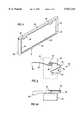
- FIG. 1is a perspective view from the front of a table made in accordance with the present invention with the under structure appearing visible through the tabletop for the sake of clarity.
- FIG. 2is a side view, on an enlarged scaled, of the table shown in FIG. 1.
- FIG. 3is a side view of the table shown in FIG. 1 showing the table in its flat position.
- FIG. 4is a perspective view of the modesty panel of the table shown in FIG. 1.
- FIG. 5is a rear view of the table shown in FIG. 1.
- FIG. 6is a top view of a leg lock locking one of the legs of the table shown in FIG. 1.
- FIG. 6Ais a side view of a leg lock shown in FIG. 6.
- FIG. 7is a side view of a top hinge of the table shown in FIG. 1.
- FIG. 7Ais a top view of the top hinge shown in FIG. 7.
- FIG. 7Bis a front view of the top hinge shown in FIG. 7.
- FIG. 8is an exploded view of the rear hinge section of the top hinge shown in FIG. 7.
- FIG. 9is a partial rear view showing the top arm of a leg supporting the tabletop.
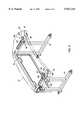
- FIG. 10is a bottom view of the table shown in FIG. 1 connected to another table.
- FIG. 11is a perspective view from the front of the table showing a second embodiment of a leg lock.
- FIGS. 1, 2, and 3Shown in FIGS. 1, 2, and 3 is a foldable table 10 having a tabletop 12, a modesty panel 14 on the front end of the table, and a right leg 16 and a left leg 18 for supporting the table.
- the table 10is foldable between an open position as shown in FIGS. 1 and 2, and a substantially flat position as shown in FIG. 3 where the legs 16, 18 and tabletop 12 are folded.
- the legs 16 and 18are each hingeably connected to the modesty panel 14 by a leg hinge 20 which allows the legs 16, 18 to move as shown by arrows 22a, 22b (FIG. 1) to their flat position adjacent the modesty panel 14. Any suitable hinge may be used.
- the tabletop 12is attached to the modesty panel 14 by a top hinge 24 which allows the top 12 to fold to its substantially flat position over the legs 16, 18 as shown in FIG. 3.
- the table 10is easily folded into a flat position for storage and transportation.
- the top 12can be constructed of any suitable material.
- itis constructed of a wood composite board laminated with a high-pressure laminate on the top, phenolic resin backer, and edge circumference with a plastic T-molding. Threaded steel inserts are provided in the underside of the table for attaching the top 12 to the top hinge 24 as further described below.
- the tabletopis shaped to allow the table to be connected to other like tables to form a wide range of configurations. This feature is further discussed in U.S.
- the modesty panel 14is now described with reference to FIG. 4 showing the modesty panel from the front side of the table 12 (FIG. 1 is a frontal view).
- the modesty panel 14has a steel tube 26 across the top, and two steel tubes 28 and 30 on each side fixed together by means such as welding.
- a formed sheet metal panel 32 in the center having folded ends 34 and a J-shaped bottom end 35 for rigidityis mig welded to the steel tubes 26, 28, 30.
- the modesty panel 14has openings 36 at the top of the sheet metal panel 32 to be used to carry the flat folded table 10 and for running wires and cables to the table.
- the top of the opening 36is bordered by the steel tube 26 which acts as a handle.
- a grommet 38 having a flange 39 screwed to the underside of the steel tube 26covers the potentially sharp sheet metal edges and provides an aesthetic appearance.
- the left and right legs 16 and 18, respectively,have a top arm 40 which supports the tabletop 12, a vertical member 42 adjacent the modesty panel 14, a second vertical member 44, and a bottom member 46.
- the top arm 40, vertical member 42, second vertical member 44, and bottom member 46are each made of steel tubes welded together to form a complete leg 16, 18.
- a spacer member 48such as a spacer button made of plastic as shown in FIG. 2 is attached to the top arm 40 with a screw.
- the spacer member 48supports the underside of the tabletop 12 in a spaced relationship from the top arm 40 as shown, and further acts as a locking member as further described below.
- Leg locks 50are provided to temporarily lock each leg 16, 18 in its open position (see FIG. 1).
- a preferred leg lockis described with reference to FIGS. 1, 6, and 6A.
- the leg lock 50has a spring bracket 52 fixed with screws through screw holes 54 to the underside of the tabletop 12.
- the spring bracket 52made out of a suitable material, such as spring steel, is shaped to hold the spacer member 48 which is attached to the top arm 40 of a leg 18. It is seen that the leg 18 is swung in the direction 55 as shown into its opened position, the spacer member 48 contacts the leg lock spring 52, moving the spring 52 back to allow the spacer member 48 to pass.
- the leg lock spring 52springs back into place to lock the leg in its open position by holding the spacer member 48 at the curved holding area 58.
- the leg 18is released for folding into its flat position by moving the handle 56 in the direction 59 as shown to release the spacer member 48.
- a similar leg lockis used for the leg 16, although the spring bracket used with the leg 16 is a mirror image of the leg lock 50 used with the leg 18 since the leg 16 swings in the opposite direction.
- the top hinge 24 connecting the tabletop 12 to the modesty panel 14is illustrated with reference to FIGS. 2, 3, 7, 7A, 7B, and 8 showing the top hinge 24 on the left side of the table 10.
- the top hinge 24includes two sections as shown in FIG. 7--a front hinge section 60 fixed to the modesty panel 14, and a rear hinge section 62 fixed to the underside of the tabletop 12.
- the top hinge sections 60 and 62are connected to each other at pivot point 64.
- the front hinge section 60is welded to the side of the modesty panel 14 as shown in FIG. 2 and 3 where it does not interfere with the folding of the leg 18. It is made of heavy gauge steel and formed with a hole 63 for the pivot point 64. The hole 63 is offset from the modesty panel 14 to allow the tabletop 12 pivoting about pivot 64 to fold over the folded legs 16, 18 (see FIG. 3).
- the rear hinge section 62is fixed to the underside of the tabletop 12 with mounting screws through screw holes 66 into the threaded steel inserts provided in the underside of the tabletop 12 as previously discussed (FIGS. 1, 7, 7A).
- the rear hinge section 62is formed with a recess 68 (FIG. 7B) to allow the leg 18 to pass under the mounting screws in screw holes 66 and with suitable mounting area for the weight of the tabletop 12 and the number of screws.
- the rear hinge section 62may further have a C-shaped mounting section 70 (FIG. 7B) for receiving and holding the top arm 40 of the leg 18 when the leg 18 is in its open position. (See FIG. 9 showing the leg 16 in a second top hinge 74 on the right side of the table 12).
- a hole 71(FIG. 8) corresponding to the hole 63 in the front hinge section 60, is provided through which a large, heavy-duty solid rivet 72 pivotally connects the rear hinge section 62 with the front hinged section 60 at pivot point 64.
- the pivot point 64is positioned so that the tabletop 12, folding about the pivot point 64, will fold over the folded legs 16, 18 to allow the tabletop 12 to fold flat, forming the flat position of the table 10 with the legs 16, 18 sandwiched between the modesty panel 14 and the tabletop 12.
- the flat folded tableis conveniently stored and transported in this position.
- the folded tabletop 12allows easy access to the handle openings 36 for carrying the folded table.
- top hinge 24Two such top hinges are shown, the top hinge 24 on the left side of the table 10, and the second top hinge 74 on the right side of the table. These two hinges 24 and 74 are mirror images of each other with the exception that the left top hinge 24 includes a lock 76 to lock the tabletop 12 in its folded position.
- the lock 76 of the illustrated embodimentis an integral part of the top hinge 24.
- a slide bolt 78is movably secured to the rear hinge section 62 by a U-shaped saddle 80 formed in the side of the rear hinge section 62 (FIG. 8).
- the slide bolt 78is shaped as shown to form a handle 82 for operating the lock, and to abut one end of a spring 84, such as the "S" spring shown, which urges the slide bolt 78 towards the front hinge section 60.
- a cover cap 86 made of sheet metalis spot welded in place over the spring 84 which fixes the other end of the spring 84 in place.
- the lock 76further includes a locking notch 88 (FIG. 7), fixed to the front hinge section 60 and which is positioned to receive the slide bolt 78 when the tabletop 12 is in the folded position (see FIG. 3).
- the locking notch 88can be integrally formed as part of the front hinge section 60.
- the front hinge section 60also has a curved surface 90 (FIG. 7) which engages the slide bolt 78 as the tabletop 12 moves from its open position to its flat position.
- the slide bolt 78moves against the urging of the spring 84 until the slide bolt 78 reaches the locking notch 88 and "snaps" therein to lock the tabletop 12, as well as the entire table 10, in the flat position as shown in FIG. 3.
- the handle 82is pulled away from the locking notch 88 to release the slide bolt 78 therefrom at which time the tabletop 12 can be moved to its open position.
- top hinge lock 76Only one top hinge lock 76 is required to lock the table 10 in the flat position.
- the lock 76can be included with the second top hinge 74 on the right side rather than or in addition to the lock 76 with the left top hinge 24.
- the present inventionis ideal for use where tables are constantly being repositioned and stored between uses.
- the tableis easily carried to the desired position by use of the handles provided by openings 36.
- the handle 82 of lock 76is pulled to release the lock 76.
- the tabletop 12is then moved to its opened position and the legs 16, 18 swung into their opened position extending under and supporting the tabletop 12.
- the top arm 40 of each leg 16, 18is moved into the C-shaped section 70 of the respective top hinge 72, 24 until the leg spring 52 takes hold of the spacer member 48 to lock the legs in place.
- Wires and cables run to equipment on the tablecan pass through the openings 36 in the modesty panel 14.
- Multiple tables 10, 10acan be connected together with connector brackets 92 as shown in FIG. 10. Connected at one end to the underside of the tabletop 12, the bracket is slotted to connect to screw 94 having knobs which can be tightened to secure the two tables 10 and 10a together.
- the handle 56 of the leg locking springs 52are pulled to release the legs 16 and 18 which can then be folded flat against the modesty panel 14.
- the tabletop 12is then folded down flat until the lock 76 of the left top hinge 24 locks the tabletop in place.
- the legs, being sandwiched between the tabletop 12 and the modesty panel 14,is thus also locked in the flat position.
- leg lock 50asuitable for use with the table 10 is illustrated in FIG. 11.
- Leg lock 50acomprises a mounting flange 96 secured to the underside of tabletop 12 by fasteners 98 such as screws. Integrally cantilevered from bracket 96 is a flat spring plate 100 having a downwardly extending engaging member 102 such as the tab shown which is punched from the surface of plate 100.
- a manual release flange 104extends from the end of spring plate 100 and is formed as an integral angled section of spring plate 100 as shown.
- leg lock 50ais formed from a spring steel or similar material and is preformed to extend downwardly at a relatively shallow angle from the undersurface of tabletop 12.
- Each leg lock 50aengages the top arm 40 of legs 16 and 18 when the legs are pivoted outwardly on leg hinges 20 to support tabletop 12.
- the engaging member 102 on each lock 50aengages an opening positioned in each respective top arm 40 to lock the legs 16, 18 in place when the legs are in the fully open position.
- leg locks 50acan be disengaged from top arms 40 by manually forcing release flanges 104 upward away from top arm 40, thereby bending cantilevered spring plate 100 and removing the engaging member 102 from the opening in the top arms 40 to permit movement of the legs.
Landscapes
- Tables And Desks Characterized By Structural Shape (AREA)
Abstract
Description
This application claims the benefit of U.S. Provisional Application No. 60/019,545 filed Jun. 10, 1996.
1. Field of the Invention
This invention relates generally to furniture and, more particularly, to a table that can fold flat for easy storage.
2. Background of the Invention
Tables that can be easily stored, transported, and erected are desirable for many types of use. One example is contemporary training environments such as hotels, convention centers, schools, colleges, and work places where it is common practice to set up temporary training classrooms. Tables used in such environments are constantly being moved and set up, and should have the ability to be stored with minimum space when not in use. Such tables should also be sufficiently supported and capable of working in contemporary environments such as with computers where many cables and wires are run to each table.
Foldable tables that can be folded to require less storage space are broadly known, but certain disadvantages flow from each proposed prior art solution to this problem. Improvement to known tables has been found to be possible and is herein disclosed for use in today's multi-purpose community and training room environments.
Accordingly, one object of the present invention is to provide a table that can fold substantially flat for easy storage and transport.
Another object is to provide a table that is easily set up for use.
A further object of the present invention is to provide a table having a top hinge that allows the tabletop to fold over the folded legs.
Another object is to provide a table that is easily locked into its flat position to ease handling.
Additional objects, advantages and novel features of the invention will be set forth in part in the description and drawings which follow, and in part will become apparent to those skilled in the art upon examination of the following or may be learned by practice of the invention. The objects and advantages of the invention may be realized and attained by means of the instrumentalities and combinations particularly pointed out in the appended claims.
The present invention provides a table foldable into a flat position that is easy to store, transport, and set up into its open position. Broadly, the invention provides a table having a tabletop, a modesty panel, and at least two legs supporting the table. Each leg is hingeably attached to the modesty panel so that each can move from its extended position underneath the tabletop to a substantially flat position relative to the modesty panel. A top hinge attaches the tabletop to the modesty panel. The top hinge has a front hinge section fixed to the modesty panel and a rear hinge section fixed to the tabletop. The two hinge sections are pivotally connected to each other at a pivot point which is offset from the modesty panel so that the tabletop can fold into a substantially flat position over the legs when the legs are in their flat position. The top hinge further has a lock to temporarily lock the tabletop in its folded position.
A preferred lock includes a slide bolt slidably fixed to the rear hinge section. A locking notch is provided with the front hinge section and positioned to receive the slide bolt when the tabletop is in the flat position. A spring urges the slide bolt towards the locking notch when the slide bolt is aligned with the notch.
The foregoing Summary as well as the following Detailed Description, will be better understood when read in conjunction with the accompanying drawings. For the purpose of illustrating the invention, there is shown in the drawings a preferred embodiment. It is understood, however, that this invention is not limited to the precise arrangement shown.
FIG. 1 is a perspective view from the front of a table made in accordance with the present invention with the under structure appearing visible through the tabletop for the sake of clarity.
FIG. 2 is a side view, on an enlarged scaled, of the table shown in FIG. 1.
FIG. 3 is a side view of the table shown in FIG. 1 showing the table in its flat position.
FIG. 4 is a perspective view of the modesty panel of the table shown in FIG. 1.
FIG. 5 is a rear view of the table shown in FIG. 1.
FIG. 6 is a top view of a leg lock locking one of the legs of the table shown in FIG. 1.
FIG. 6A is a side view of a leg lock shown in FIG. 6.
FIG. 7 is a side view of a top hinge of the table shown in FIG. 1.
FIG. 7A is a top view of the top hinge shown in FIG. 7.
FIG. 7B is a front view of the top hinge shown in FIG. 7.
FIG. 8 is an exploded view of the rear hinge section of the top hinge shown in FIG. 7.
FIG. 9 is a partial rear view showing the top arm of a leg supporting the tabletop.
FIG. 10 is a bottom view of the table shown in FIG. 1 connected to another table.
FIG. 11 is a perspective view from the front of the table showing a second embodiment of a leg lock.
Reference is now made to the drawings illustrating a preferred embodiment of the invention. Shown in FIGS. 1, 2, and 3 is a foldable table 10 having atabletop 12, amodesty panel 14 on the front end of the table, and aright leg 16 and aleft leg 18 for supporting the table.
The table 10 is foldable between an open position as shown in FIGS. 1 and 2, and a substantially flat position as shown in FIG. 3 where thelegs tabletop 12 are folded. Thelegs modesty panel 14 by aleg hinge 20 which allows thelegs arrows modesty panel 14. Any suitable hinge may be used.
Thetabletop 12 is attached to themodesty panel 14 by atop hinge 24 which allows thetop 12 to fold to its substantially flat position over thelegs
The top 12 can be constructed of any suitable material. For the preferred embodiment, it is constructed of a wood composite board laminated with a high-pressure laminate on the top, phenolic resin backer, and edge circumference with a plastic T-molding. Threaded steel inserts are provided in the underside of the table for attaching thetop 12 to thetop hinge 24 as further described below. The tabletop is shaped to allow the table to be connected to other like tables to form a wide range of configurations. This feature is further discussed in U.S. patent application Ser. No. 08/642,750, filed May 3, 1996, entitled: "Table Having Tripartite End Segments and System Utilizing Same," assigned to the assignee of the present application, which is hereby incorporated by reference.
Themodesty panel 14 is now described with reference to FIG. 4 showing the modesty panel from the front side of the table 12 (FIG. 1 is a frontal view). In the illustrated embodiment, themodesty panel 14 has asteel tube 26 across the top, and twosteel tubes sheet metal panel 32 in the center having folded ends 34 and a J-shapedbottom end 35 for rigidity is mig welded to thesteel tubes
With reference to FIGS. 4 and 5, themodesty panel 14 hasopenings 36 at the top of thesheet metal panel 32 to be used to carry the flat folded table 10 and for running wires and cables to the table. The top of theopening 36 is bordered by thesteel tube 26 which acts as a handle. Agrommet 38 having aflange 39 screwed to the underside of thesteel tube 26 covers the potentially sharp sheet metal edges and provides an aesthetic appearance.
Referring to FIGS. 1 and 2, the left andright legs top arm 40 which supports thetabletop 12, avertical member 42 adjacent themodesty panel 14, a secondvertical member 44, and abottom member 46. Thetop arm 40,vertical member 42, secondvertical member 44, andbottom member 46 are each made of steel tubes welded together to form acomplete leg
Aspacer member 48, such as a spacer button made of plastic as shown in FIG. 2 is attached to thetop arm 40 with a screw. Thespacer member 48 supports the underside of thetabletop 12 in a spaced relationship from thetop arm 40 as shown, and further acts as a locking member as further described below.
Leg locks 50 are provided to temporarily lock eachleg leg lock 50 has aspring bracket 52 fixed with screws through screw holes 54 to the underside of thetabletop 12. Thespring bracket 52, made out of a suitable material, such as spring steel, is shaped to hold thespacer member 48 which is attached to thetop arm 40 of aleg 18. It is seen that theleg 18 is swung in thedirection 55 as shown into its opened position, thespacer member 48 contacts theleg lock spring 52, moving thespring 52 back to allow thespacer member 48 to pass. Theleg lock spring 52 springs back into place to lock the leg in its open position by holding thespacer member 48 at thecurved holding area 58. Theleg 18 is released for folding into its flat position by moving thehandle 56 in thedirection 59 as shown to release thespacer member 48. A similar leg lock is used for theleg 16, although the spring bracket used with theleg 16 is a mirror image of theleg lock 50 used with theleg 18 since theleg 16 swings in the opposite direction.
Thetop hinge 24 connecting thetabletop 12 to themodesty panel 14 is illustrated with reference to FIGS. 2, 3, 7, 7A, 7B, and 8 showing thetop hinge 24 on the left side of the table 10. Thetop hinge 24 includes two sections as shown in FIG. 7--afront hinge section 60 fixed to themodesty panel 14, and arear hinge section 62 fixed to the underside of thetabletop 12. Thetop hinge sections pivot point 64.
Thefront hinge section 60 is welded to the side of themodesty panel 14 as shown in FIG. 2 and 3 where it does not interfere with the folding of theleg 18. It is made of heavy gauge steel and formed with ahole 63 for thepivot point 64. Thehole 63 is offset from themodesty panel 14 to allow thetabletop 12 pivoting aboutpivot 64 to fold over the foldedlegs 16, 18 (see FIG. 3).
Therear hinge section 62 is fixed to the underside of thetabletop 12 with mounting screws through screw holes 66 into the threaded steel inserts provided in the underside of thetabletop 12 as previously discussed (FIGS. 1, 7, 7A). Therear hinge section 62 is formed with a recess 68 (FIG. 7B) to allow theleg 18 to pass under the mounting screws in screw holes 66 and with suitable mounting area for the weight of thetabletop 12 and the number of screws. Therear hinge section 62 may further have a C-shaped mounting section 70 (FIG. 7B) for receiving and holding thetop arm 40 of theleg 18 when theleg 18 is in its open position. (See FIG. 9 showing theleg 16 in a secondtop hinge 74 on the right side of the table 12). Heavy gauge steel is preferred for forming this section. A hole 71 (FIG. 8) corresponding to thehole 63 in thefront hinge section 60, is provided through which a large, heavy-dutysolid rivet 72 pivotally connects therear hinge section 62 with the front hingedsection 60 atpivot point 64.
As previously discussed, thepivot point 64 is positioned so that thetabletop 12, folding about thepivot point 64, will fold over the foldedlegs tabletop 12 to fold flat, forming the flat position of the table 10 with thelegs modesty panel 14 and thetabletop 12. The flat folded table is conveniently stored and transported in this position. Moreover, the foldedtabletop 12 allows easy access to thehandle openings 36 for carrying the folded table.
Two such top hinges are shown, thetop hinge 24 on the left side of the table 10, and the secondtop hinge 74 on the right side of the table. These two hinges 24 and 74 are mirror images of each other with the exception that the lefttop hinge 24 includes a lock 76 to lock thetabletop 12 in its folded position.
Referring to FIGS. 2, 3, 7, and 8, the lock 76 of the illustrated embodiment is an integral part of thetop hinge 24. Aslide bolt 78 is movably secured to therear hinge section 62 by a U-shaped saddle 80 formed in the side of the rear hinge section 62 (FIG. 8). Theslide bolt 78 is shaped as shown to form ahandle 82 for operating the lock, and to abut one end of aspring 84, such as the "S" spring shown, which urges theslide bolt 78 towards thefront hinge section 60. Acover cap 86 made of sheet metal is spot welded in place over thespring 84 which fixes the other end of thespring 84 in place.
The lock 76 further includes a locking notch 88 (FIG. 7), fixed to thefront hinge section 60 and which is positioned to receive theslide bolt 78 when thetabletop 12 is in the folded position (see FIG. 3). As illustrated, the lockingnotch 88 can be integrally formed as part of thefront hinge section 60. Thefront hinge section 60 also has a curved surface 90 (FIG. 7) which engages theslide bolt 78 as thetabletop 12 moves from its open position to its flat position. In moving to the flat position of FIG. 3, theslide bolt 78 moves against the urging of thespring 84 until theslide bolt 78 reaches the lockingnotch 88 and "snaps" therein to lock thetabletop 12, as well as the entire table 10, in the flat position as shown in FIG. 3. To open thetabletop 12 from the flat position, thehandle 82 is pulled away from the lockingnotch 88 to release theslide bolt 78 therefrom at which time thetabletop 12 can be moved to its open position.
Only one top hinge lock 76 is required to lock the table 10 in the flat position. The lock 76 can be included with the secondtop hinge 74 on the right side rather than or in addition to the lock 76 with the lefttop hinge 24.
The present invention is ideal for use where tables are constantly being repositioned and stored between uses. The table is easily carried to the desired position by use of the handles provided byopenings 36. To open, thehandle 82 of lock 76 is pulled to release the lock 76. Thetabletop 12 is then moved to its opened position and thelegs tabletop 12. Thetop arm 40 of eachleg section 70 of the respectivetop hinge leg spring 52 takes hold of thespacer member 48 to lock the legs in place. This completes the table setup. Wires and cables run to equipment on the table can pass through theopenings 36 in themodesty panel 14. Multiple tables 10, 10a can be connected together withconnector brackets 92 as shown in FIG. 10. Connected at one end to the underside of thetabletop 12, the bracket is slotted to connect to screw 94 having knobs which can be tightened to secure the two tables 10 and 10a together.
To fold the table to its flat position, thehandle 56 of the leg locking springs 52 are pulled to release thelegs modesty panel 14. Thetabletop 12 is then folded down flat until the lock 76 of the lefttop hinge 24 locks the tabletop in place. The legs, being sandwiched between thetabletop 12 and themodesty panel 14, is thus also locked in the flat position.
A second type ofleg lock 50a suitable for use with the table 10 is illustrated in FIG. 11.Leg lock 50a comprises a mountingflange 96 secured to the underside oftabletop 12 byfasteners 98 such as screws. Integrally cantilevered frombracket 96 is aflat spring plate 100 having a downwardly extending engagingmember 102 such as the tab shown which is punched from the surface ofplate 100. Amanual release flange 104 extends from the end ofspring plate 100 and is formed as an integral angled section ofspring plate 100 as shown. Preferably,leg lock 50a is formed from a spring steel or similar material and is preformed to extend downwardly at a relatively shallow angle from the undersurface oftabletop 12. Eachleg lock 50a engages thetop arm 40 oflegs tabletop 12. The engagingmember 102 on eachlock 50a engages an opening positioned in each respectivetop arm 40 to lock thelegs leg locks 50a can be disengaged fromtop arms 40 by manually forcingrelease flanges 104 upward away fromtop arm 40, thereby bending cantileveredspring plate 100 and removing the engagingmember 102 from the opening in thetop arms 40 to permit movement of the legs.
While a particular embodiment of the invention is described herein, it is not intended to limit the invention to such disclosure. Changes and modifications made be incorporated and embodied within the scope of the appended claims.
Claims (12)
1. A table foldable between an open and a flat position, said table comprising:
a table top;
a modesty panel;
at least two legs for supporting the table each leg comprising a vertical member hingeably attached to said modesty panel allowing said leg to move into a substantially flat position relative to said modesty panel when said table is in the flat position and allowing said leg to extend underneath said table top to support said table top when said table is in the open position, each said leg including a top arm member supporting the underside of said table top when said table is in the open position;
a top hinge attaching said table top to said modesty panel, said top hinge having a front hinge section fixed to said modesty panel and a rear hinge section fixed to said table top, said front and rear sections being pivotally connected to each other at a pivot point offset from said modesty panel so that said table top can fold into a substantially flat position relative to said modesty panel over said legs when the legs are in the flat position, said top hinge further comprising a lock to temporarily lock said table top in the folded position; and
a leg lock fixed to the underside of said table top for locking said table top to said legs when said table is in the open position, said leg lock comprising a locking spring fixed to the underside of said table top and shaped to secure one of said legs when the table is in the open position, said locking spring being moveable to release said one leg to allow the leg to fold into its flat position.
2. A table in accordance with claim 1 wherein said lock comprises:
a moveable slide bolt secured to said rear hinge section and having a handle;
a locking notch fixed to said front hinge section and disposed to receive said slide bolt when said table top is in the folded position; and
a spring urging said bolt towards said locking notch.
3. A table in accordance with claim 2 wherein said modesty panel comprises multiple openings sized to accept hands for carrying the table and for wire management.
4. A table in accordance with claim 3 further comprising a grommet fixed around the inside edge of each said openings in said modesty panel.
5. A table in accordance with claim 1 further comprising
a spacer member attached to the top arm member of each said leg to support the underside of said table top in a spaced relationship relative to said top arm; and
wherein said locking spring is shaped to engage and hold said spacer member when said table is in the open position, and wherein said locking spring includes a handle to release said spacer member.
6. A table in accordance with claim 1 wherein said lock comprises:
a moveable slide bolt secured to said rear hinge section and having a handle;
a locking notch fixed to said front hinge section and disposed to accept said slide bolt when said table top is in the folded position; and
a spring urging said bolt towards said locking notch.
7. A table foldable between an open and a flat position, said table comprising:
a table top;
a modesty panel;
at least two legs for supporting the table, each leg being hingeably attached to said modesty panel allowing said leg to move to a substantially flat position, relative to said modesty panel when said table is in the flat position and allowing said leg to extend underneath said table top to support said table top when said table is in the open position, each of said legs comprising a vertical member hingeably attached to said modesty panel, and a top arm member supporting the underside of said table top when said table is in the open position, said top arm including a spacer member disposed to support the underside of said table top in a spaced relationship relative to said top arm when said table is in the open position;
a bracket fixed to the underside of said table top shaped to engagingly secure said spacer member when said table is in the open position, said bracket including a handle to release said spacer member; and
a top hinge attaching said table top to said modesty panel, said top hinge comprising:
(a) a rear hinge section secured to the underside of the table top;
(b) a slide bolt slidably fixed to the said rear hinge section;
(c) a front hinge section secured to the modesty panel, said front hinge section having a locking notch adapted to receive said slide bolt when said table top is in the flat position;
(d) said front and rear hinge sections being pivotally connected to each other at a point offset from said modesty panel so that said table top can fold into a substantially flat position relative to said modesty panel over said legs when the table is in the flat position; and
(e) a spring disposed to urge said slide bolt toward said locking notch to lock said table in its flat position.
8. A table in accordance with claim 7 further comprising a leg lock fixed to the underside of said table to securely hold one of said legs in the open position.
9. A table in accordance with claim 7 further comprising a second top hinge attaching said tabletop to said modesty panel, said second top hinge comprising a second rear hinge section secured to the underside of the tabletop and a second front hinge section secured to the modesty panel, said second rear and front sections being pivotally connected to each other at a point offset from said modesty panel so that said table top can fold into a substantially flat position relative to said modesty panel over said legs when the table is in the flat position.
10. A table in accordance with claim 7 wherein said front and rear hinge sections are pivotally connected to each other with a rivet.
11. A table in accordance with claim 7 further comprising a connector bracket on the underside of the table for securing said table to another table.
12. A table in accordance with claim 7 wherein said tabletop has a convex front side, a concave rear side, and at least one end having tripartite edge segments.
Priority Applications (1)
| Application Number | Priority Date | Filing Date | Title |
|---|---|---|---|
| US08/871,325US5927214A (en) | 1996-06-10 | 1997-06-09 | Flat folding table |
Applications Claiming Priority (2)
| Application Number | Priority Date | Filing Date | Title |
|---|---|---|---|
| US1954596P | 1996-06-10 | 1996-06-10 | |
| US08/871,325US5927214A (en) | 1996-06-10 | 1997-06-09 | Flat folding table |
Publications (1)
| Publication Number | Publication Date |
|---|---|
| US5927214Atrue US5927214A (en) | 1999-07-27 |
Family
ID=21793787
Family Applications (1)
| Application Number | Title | Priority Date | Filing Date |
|---|---|---|---|
| US08/871,325Expired - LifetimeUS5927214A (en) | 1996-06-10 | 1997-06-09 | Flat folding table |
Country Status (2)
| Country | Link |
|---|---|
| US (1) | US5927214A (en) |
| CA (1) | CA2207486C (en) |
Cited By (55)
| Publication number | Priority date | Publication date | Assignee | Title |
|---|---|---|---|---|
| USD424325S (en)* | 1998-11-09 | 2000-05-09 | Alfonso Iannaccone | Folding table |
| US6170407B1 (en)* | 1999-07-26 | 2001-01-09 | Spec Furniture Inc. | Folding leg mechanism |
| USD441572S1 (en) | 2000-01-31 | 2001-05-08 | Steelcase Development Inc. | Table |
| US6240855B1 (en)* | 1999-04-30 | 2001-06-05 | Table Guys, Inc. | Convertible portable table assembly |
| WO2001054538A1 (en)* | 2000-01-31 | 2001-08-02 | Steelcase Development Inc. | Table configured for utilities, ganging and storage |
| US6314892B1 (en)* | 1999-06-21 | 2001-11-13 | Peter B. Favini | Foldable table |
| US6336414B1 (en) | 2001-01-31 | 2002-01-08 | Steelcase Development Corp | Table configured for utilities, ganging and storage |
| US6647900B1 (en)* | 2000-10-06 | 2003-11-18 | Krueger International, Inc. | Folding training table with wire manager pivotably mounted to and between a pair of legs |
| US6675722B2 (en)* | 2002-03-13 | 2004-01-13 | Peter Stathis | Workhorse table base |
| US6698364B2 (en)* | 2001-08-03 | 2004-03-02 | Metro Industries, Inc. | Folding work station |
| US20040083932A1 (en)* | 2002-10-31 | 2004-05-06 | Kottman Mark A. | Folding and tilting table |
| US6752090B2 (en)* | 2002-03-22 | 2004-06-22 | Innovative Storage Designs, Inc. | Folding desk |
| US6776077B1 (en)* | 2003-03-26 | 2004-08-17 | Chieh-Tang Chen | Roller blade cutting device |
| US20040237854A1 (en)* | 2001-06-15 | 2004-12-02 | Giancarlo Piretti | Folding table |
| US20050127799A1 (en)* | 2002-12-30 | 2005-06-16 | Arent Thomas W. | Modular workbench system |
| US20050252426A1 (en)* | 2004-05-14 | 2005-11-17 | Blasen Steven T | Nesting table with controlled pivoting movement |
| US20070137534A1 (en)* | 2005-12-15 | 2007-06-21 | Dhanoa David S | Flip top table |
| US20070209559A1 (en)* | 2006-03-08 | 2007-09-13 | Wini Buromobel Georg Schmidt Gmbh & Co. Kg | Table with a swivelable table top |
| US20070256611A1 (en)* | 2006-05-08 | 2007-11-08 | Tsung-Chieh Huang | Telescopic and foldable table |
| US20070261609A1 (en)* | 2006-05-15 | 2007-11-15 | Aichi Co., Ltd. | Locking device and furniture |
| US20080017083A1 (en)* | 2006-06-30 | 2008-01-24 | Vannimwegen Edward G | Table |
| US20080050173A1 (en)* | 2006-08-23 | 2008-02-28 | Veyl Gmbh | Connecting element |
| US20080295744A1 (en)* | 2007-05-29 | 2008-12-04 | Kimball International, Inc. | Multi-purpose table with electrical features |
| US20080295742A1 (en)* | 2007-05-29 | 2008-12-04 | Kimball International, Inc. | Multi-purpose table with electrical features |
| US20090205541A1 (en)* | 2008-02-14 | 2009-08-20 | Dsa International | Flip-Top Table Mechanism |
| US7634968B2 (en) | 2001-10-02 | 2009-12-22 | Christian Cornelius | Pivotable board provided with legs |
| WO2010083425A3 (en)* | 2009-01-18 | 2010-10-28 | Bretford Manufacturing Inc. | Wire management vanity panel for folding table |
| US20100300242A1 (en)* | 2009-05-27 | 2010-12-02 | Josef Rutz | Locking mechanism |
| US20110017107A1 (en)* | 2009-07-25 | 2011-01-27 | Wen-Shan Ko | Folding table |
| US20110036277A1 (en)* | 2007-09-08 | 2011-02-17 | Mike Prendergast | Foldable table |
| US20110155021A1 (en)* | 2009-12-30 | 2011-06-30 | Cwg Inc. | Folding desk |
| US8069795B1 (en) | 2009-06-11 | 2011-12-06 | Krueger International, Inc. | Grip latch and hinge mechanism for a flip table |
| US20120186500A1 (en)* | 2011-01-20 | 2012-07-26 | Yu-Cheng Liu | Rapidly assembled office desk |
| US8359983B2 (en)* | 2011-06-02 | 2013-01-29 | Halcon Inc. | Adjustable table apparatus and method |
| US20130284076A1 (en)* | 2010-10-27 | 2013-10-31 | Okamura Corporation | Folding table |
| US20140261099A1 (en)* | 2013-03-14 | 2014-09-18 | Emory University | Surgical support device |
| US20150033990A1 (en)* | 2013-08-05 | 2015-02-05 | John Francis YEAGER | Protective student desk |
| US20150257526A1 (en)* | 2014-03-11 | 2015-09-17 | Jennifer Ying Lai | Folding table |
| US20150259981A1 (en)* | 2014-03-14 | 2015-09-17 | Zdzislaw Bobek | Ladder Guard |
| US9161623B1 (en)* | 2014-04-15 | 2015-10-20 | Zhuhai Shichang Metals Ltd. | Tabletop linking device |
| US20160198841A1 (en)* | 2015-01-08 | 2016-07-14 | Dates Weiser Furniture Corporation | Collapsible table |
| US9655445B2 (en)* | 2015-09-30 | 2017-05-23 | Workrite Ergonomics, Llc | Table benching apparatus and methods of using the same |
| US9676604B2 (en) | 2014-03-21 | 2017-06-13 | Aisle Advertising | Convertible beverage serving station |
| US9895201B2 (en) | 2015-02-27 | 2018-02-20 | Flex Operating Room, Llc | Cantilever organizational rack system for supporting surgical instrumentation |
| US10271917B2 (en) | 2015-02-27 | 2019-04-30 | Flex Operating Room, Llc | Surgical tray efficiency system and related methods |
| US10295311B1 (en)* | 2018-05-22 | 2019-05-21 | First Line Furniture, LLC | Flip-top table for protection from projectiles |
| USD849453S1 (en)* | 2017-11-29 | 2019-05-28 | Yajun Hu | Foldable desk |
| US10595630B2 (en)* | 2017-10-20 | 2020-03-24 | Virco Mfg. Corporation | Adjustable table assembly |
| US10646033B2 (en) | 2018-03-02 | 2020-05-12 | Ergotron, Inc. | Height adjustable platforms and associated mechanisms |
| US10758038B2 (en)* | 2018-05-29 | 2020-09-01 | Knoll, Inc. | Article of furniture and method of using the same |
| US10866068B1 (en)* | 2018-05-22 | 2020-12-15 | First Line Furniture, LLC | Flip-top table for protection from projectiles |
| US11071377B2 (en) | 2018-03-02 | 2021-07-27 | Ergotron, Inc. | Height adjustable platforms and associated mechanisms |
| US11122886B1 (en) | 2020-05-13 | 2021-09-21 | Halcon Corp. | Adjustable table apparatus and method |
| US11229284B1 (en)* | 2018-05-22 | 2022-01-25 | First Line Furniture, LLC | Flip-top table for protection from projectiles |
| US11672333B2 (en) | 2020-09-09 | 2023-06-13 | Ronald Giery | Flip top table with a nested leg assembly |
Families Citing this family (1)
| Publication number | Priority date | Publication date | Assignee | Title |
|---|---|---|---|---|
| GB0507947D0 (en)* | 2005-04-19 | 2005-05-25 | Mad Design Co Ltd | Improvements to a table |
Citations (15)
| Publication number | Priority date | Publication date | Assignee | Title |
|---|---|---|---|---|
| GB189609718A (en)* | 1896-05-07 | 1897-05-01 | James Robertson | Improvements in and relating to Folding Tables, Stands, and other Articles of Furniture. |
| US2708146A (en)* | 1954-01-26 | 1955-05-10 | Shwayder Brothers Inc | Table leg mounting bracket and latch structure therefor |
| US2750243A (en)* | 1954-07-06 | 1956-06-12 | William A Zielfeldt | Foldable table with hinged top |
| US2971803A (en)* | 1959-07-06 | 1961-02-14 | Wallin Frederick | Multi-position leg bracket |
| CA754962A (en)* | 1967-03-21 | D. Knoblock Frederick | Folding table | |
| US3861329A (en)* | 1973-06-25 | 1975-01-21 | Wilkie Philip H | Lockable furniture leg |
| GB2137488A (en)* | 1983-01-24 | 1984-10-10 | Dantville Limited | Furniture unit |
| US4602889A (en)* | 1984-08-31 | 1986-07-29 | Mu Shan Yeh | Adjustable knuckle joint device for folding ladders |
| WO1990003132A1 (en)* | 1988-09-22 | 1990-04-05 | Brian James Morgan | Improvements relating to tables |
| US5182996A (en)* | 1991-10-30 | 1993-02-02 | Ditto Sales, Inc | Pivoting bracket assembly for connecting table tops |
| US5337657A (en)* | 1992-06-01 | 1994-08-16 | Howe Furniture Corporation | Computer training and support table system |
| US5549055A (en)* | 1994-01-28 | 1996-08-27 | Kusch; Dieter | Underframe for tabletops for single and multiple tables |
| US5568773A (en)* | 1995-07-19 | 1996-10-29 | Hung; Wang-Ho | Multifunctional computer desk |
| US5640912A (en)* | 1995-01-26 | 1997-06-24 | Howe Furniture Corporation | Foldable table with detachable wire management tray |
| US5690403A (en)* | 1995-10-23 | 1997-11-25 | Steelcase Inc. | Insert for filling utility access opening in furniture panel |
- 1997
- 1997-06-09USUS08/871,325patent/US5927214A/ennot_activeExpired - Lifetime
- 1997-06-10CACA002207486Apatent/CA2207486C/ennot_activeExpired - Fee Related
Patent Citations (15)
| Publication number | Priority date | Publication date | Assignee | Title |
|---|---|---|---|---|
| CA754962A (en)* | 1967-03-21 | D. Knoblock Frederick | Folding table | |
| GB189609718A (en)* | 1896-05-07 | 1897-05-01 | James Robertson | Improvements in and relating to Folding Tables, Stands, and other Articles of Furniture. |
| US2708146A (en)* | 1954-01-26 | 1955-05-10 | Shwayder Brothers Inc | Table leg mounting bracket and latch structure therefor |
| US2750243A (en)* | 1954-07-06 | 1956-06-12 | William A Zielfeldt | Foldable table with hinged top |
| US2971803A (en)* | 1959-07-06 | 1961-02-14 | Wallin Frederick | Multi-position leg bracket |
| US3861329A (en)* | 1973-06-25 | 1975-01-21 | Wilkie Philip H | Lockable furniture leg |
| GB2137488A (en)* | 1983-01-24 | 1984-10-10 | Dantville Limited | Furniture unit |
| US4602889A (en)* | 1984-08-31 | 1986-07-29 | Mu Shan Yeh | Adjustable knuckle joint device for folding ladders |
| WO1990003132A1 (en)* | 1988-09-22 | 1990-04-05 | Brian James Morgan | Improvements relating to tables |
| US5182996A (en)* | 1991-10-30 | 1993-02-02 | Ditto Sales, Inc | Pivoting bracket assembly for connecting table tops |
| US5337657A (en)* | 1992-06-01 | 1994-08-16 | Howe Furniture Corporation | Computer training and support table system |
| US5549055A (en)* | 1994-01-28 | 1996-08-27 | Kusch; Dieter | Underframe for tabletops for single and multiple tables |
| US5640912A (en)* | 1995-01-26 | 1997-06-24 | Howe Furniture Corporation | Foldable table with detachable wire management tray |
| US5568773A (en)* | 1995-07-19 | 1996-10-29 | Hung; Wang-Ho | Multifunctional computer desk |
| US5690403A (en)* | 1995-10-23 | 1997-11-25 | Steelcase Inc. | Insert for filling utility access opening in furniture panel |
Cited By (89)
| Publication number | Priority date | Publication date | Assignee | Title |
|---|---|---|---|---|
| USD424325S (en)* | 1998-11-09 | 2000-05-09 | Alfonso Iannaccone | Folding table |
| US6240855B1 (en)* | 1999-04-30 | 2001-06-05 | Table Guys, Inc. | Convertible portable table assembly |
| US6314892B1 (en)* | 1999-06-21 | 2001-11-13 | Peter B. Favini | Foldable table |
| US6170407B1 (en)* | 1999-07-26 | 2001-01-09 | Spec Furniture Inc. | Folding leg mechanism |
| USD441572S1 (en) | 2000-01-31 | 2001-05-08 | Steelcase Development Inc. | Table |
| USD443440S1 (en) | 2000-01-31 | 2001-06-12 | Steelcase Development Inc. | Table |
| USD443776S1 (en) | 2000-01-31 | 2001-06-19 | Steelcase Development Inc. | Table leg |
| WO2001054538A1 (en)* | 2000-01-31 | 2001-08-02 | Steelcase Development Inc. | Table configured for utilities, ganging and storage |
| US6647900B1 (en)* | 2000-10-06 | 2003-11-18 | Krueger International, Inc. | Folding training table with wire manager pivotably mounted to and between a pair of legs |
| US6336414B1 (en) | 2001-01-31 | 2002-01-08 | Steelcase Development Corp | Table configured for utilities, ganging and storage |
| US7614351B2 (en)* | 2001-06-15 | 2009-11-10 | Pro-Cord S.P.A. | Folding table |
| US20040237854A1 (en)* | 2001-06-15 | 2004-12-02 | Giancarlo Piretti | Folding table |
| US6698364B2 (en)* | 2001-08-03 | 2004-03-02 | Metro Industries, Inc. | Folding work station |
| US7634968B2 (en) | 2001-10-02 | 2009-12-22 | Christian Cornelius | Pivotable board provided with legs |
| US7878128B2 (en) | 2001-10-02 | 2011-02-01 | Steelcase Development Corporation | Pivotable board provided with legs |
| US6675722B2 (en)* | 2002-03-13 | 2004-01-13 | Peter Stathis | Workhorse table base |
| US6752090B2 (en)* | 2002-03-22 | 2004-06-22 | Innovative Storage Designs, Inc. | Folding desk |
| US6845723B2 (en)* | 2002-10-31 | 2005-01-25 | Hon Technology Inc. | Folding and tilting table |
| US20040083932A1 (en)* | 2002-10-31 | 2004-05-06 | Kottman Mark A. | Folding and tilting table |
| US20050127799A1 (en)* | 2002-12-30 | 2005-06-16 | Arent Thomas W. | Modular workbench system |
| US7140701B2 (en)* | 2002-12-30 | 2006-11-28 | Whirlpool Corporation | Modular workbench system |
| US6776077B1 (en)* | 2003-03-26 | 2004-08-17 | Chieh-Tang Chen | Roller blade cutting device |
| US7066098B2 (en) | 2004-05-14 | 2006-06-27 | Hni Technologies Inc. | Nesting table with controlled pivoting movement |
| US20050252426A1 (en)* | 2004-05-14 | 2005-11-17 | Blasen Steven T | Nesting table with controlled pivoting movement |
| US20070137534A1 (en)* | 2005-12-15 | 2007-06-21 | Dhanoa David S | Flip top table |
| US7677184B2 (en) | 2005-12-15 | 2010-03-16 | Steelcase Development Corporation | Flip top table |
| US20070209559A1 (en)* | 2006-03-08 | 2007-09-13 | Wini Buromobel Georg Schmidt Gmbh & Co. Kg | Table with a swivelable table top |
| US7703400B2 (en)* | 2006-03-08 | 2010-04-27 | WINI Büromöbel Georg, Schmidt GmbH & Co. KG | Table with a swivelable table top |
| US7631604B2 (en)* | 2006-05-08 | 2009-12-15 | Tsung-Chieh Huang | Telescopic and foldable table |
| US20070256611A1 (en)* | 2006-05-08 | 2007-11-08 | Tsung-Chieh Huang | Telescopic and foldable table |
| US7836833B2 (en)* | 2006-05-15 | 2010-11-23 | Aichi Co., Ltd. | Locking device and furniture |
| US20070261609A1 (en)* | 2006-05-15 | 2007-11-15 | Aichi Co., Ltd. | Locking device and furniture |
| US20080017083A1 (en)* | 2006-06-30 | 2008-01-24 | Vannimwegen Edward G | Table |
| US20080050173A1 (en)* | 2006-08-23 | 2008-02-28 | Veyl Gmbh | Connecting element |
| US7997212B2 (en) | 2007-05-29 | 2011-08-16 | Kimball International, Inc. | Multi-purpose table with electrical features |
| US7975624B2 (en) | 2007-05-29 | 2011-07-12 | Kimball International, Inc. | Multi-purpose table with electrical features |
| US20080295744A1 (en)* | 2007-05-29 | 2008-12-04 | Kimball International, Inc. | Multi-purpose table with electrical features |
| US20080295742A1 (en)* | 2007-05-29 | 2008-12-04 | Kimball International, Inc. | Multi-purpose table with electrical features |
| US20110036277A1 (en)* | 2007-09-08 | 2011-02-17 | Mike Prendergast | Foldable table |
| US8381664B2 (en)* | 2007-09-08 | 2013-02-26 | Abf Europe Limited | Foldable table |
| US20090205541A1 (en)* | 2008-02-14 | 2009-08-20 | Dsa International | Flip-Top Table Mechanism |
| US8171863B2 (en)* | 2008-02-14 | 2012-05-08 | DSA International, Inc. | Flip-top table mechanism |
| US20110036276A1 (en)* | 2009-01-18 | 2011-02-17 | Tad Petrick | Wire Management Vanity Panel for Folding Table |
| WO2010083425A3 (en)* | 2009-01-18 | 2010-10-28 | Bretford Manufacturing Inc. | Wire management vanity panel for folding table |
| US20100300242A1 (en)* | 2009-05-27 | 2010-12-02 | Josef Rutz | Locking mechanism |
| US8272336B2 (en)* | 2009-05-27 | 2012-09-25 | Steelcase Werndl Ag | Locking mechanism |
| US8069795B1 (en) | 2009-06-11 | 2011-12-06 | Krueger International, Inc. | Grip latch and hinge mechanism for a flip table |
| US20110017107A1 (en)* | 2009-07-25 | 2011-01-27 | Wen-Shan Ko | Folding table |
| US20110155021A1 (en)* | 2009-12-30 | 2011-06-30 | Cwg Inc. | Folding desk |
| US9642451B2 (en)* | 2010-10-27 | 2017-05-09 | Okamura Corporation | Folding table |
| US20130284076A1 (en)* | 2010-10-27 | 2013-10-31 | Okamura Corporation | Folding table |
| US20120186500A1 (en)* | 2011-01-20 | 2012-07-26 | Yu-Cheng Liu | Rapidly assembled office desk |
| US8297207B2 (en)* | 2011-01-20 | 2012-10-30 | Choice Industries Corp. | Rapidly assembled office desk |
| US8359983B2 (en)* | 2011-06-02 | 2013-01-29 | Halcon Inc. | Adjustable table apparatus and method |
| US20140261099A1 (en)* | 2013-03-14 | 2014-09-18 | Emory University | Surgical support device |
| US8950344B2 (en)* | 2013-03-14 | 2015-02-10 | Emory University | Surgical support device |
| US20150033990A1 (en)* | 2013-08-05 | 2015-02-05 | John Francis YEAGER | Protective student desk |
| US20150257526A1 (en)* | 2014-03-11 | 2015-09-17 | Jennifer Ying Lai | Folding table |
| US9226572B2 (en)* | 2014-03-11 | 2016-01-05 | Jennifer Ying Lai | Folding table |
| US20150259981A1 (en)* | 2014-03-14 | 2015-09-17 | Zdzislaw Bobek | Ladder Guard |
| US9676604B2 (en) | 2014-03-21 | 2017-06-13 | Aisle Advertising | Convertible beverage serving station |
| US9161623B1 (en)* | 2014-04-15 | 2015-10-20 | Zhuhai Shichang Metals Ltd. | Tabletop linking device |
| US20160198841A1 (en)* | 2015-01-08 | 2016-07-14 | Dates Weiser Furniture Corporation | Collapsible table |
| US9950728B2 (en)* | 2015-01-08 | 2018-04-24 | Knoll, Inc. | Collapsible table |
| US11389260B2 (en) | 2015-02-27 | 2022-07-19 | Flex Operating Room, Inc. | Surgical tray efficiency system and related methods |
| US10925683B2 (en) | 2015-02-27 | 2021-02-23 | Flex Operating Room, Llc | Cantilever organizational rack system for supporting surgical instrumentation |
| US10271917B2 (en) | 2015-02-27 | 2019-04-30 | Flex Operating Room, Llc | Surgical tray efficiency system and related methods |
| US12279918B2 (en) | 2015-02-27 | 2025-04-22 | Flex Operating Room, Llc | Surgical tray efficiency system and related methods |
| US10575915B2 (en) | 2015-02-27 | 2020-03-03 | Flex Operating Room, Llc | Surgical tray efficiency system and related methods |
| US11980486B2 (en) | 2015-02-27 | 2024-05-14 | Flex Operating Room, Inc. | Surgical tray efficiency system and related methods |
| US9895201B2 (en) | 2015-02-27 | 2018-02-20 | Flex Operating Room, Llc | Cantilever organizational rack system for supporting surgical instrumentation |
| US9750344B2 (en) | 2015-09-30 | 2017-09-05 | Workrite Ergonomics, Llc | Table benching apparatus and methods of using the same |
| US9655445B2 (en)* | 2015-09-30 | 2017-05-23 | Workrite Ergonomics, Llc | Table benching apparatus and methods of using the same |
| US10595630B2 (en)* | 2017-10-20 | 2020-03-24 | Virco Mfg. Corporation | Adjustable table assembly |
| USD849453S1 (en)* | 2017-11-29 | 2019-05-28 | Yajun Hu | Foldable desk |
| US11839294B2 (en) | 2018-03-02 | 2023-12-12 | Ergotron, Inc. | Height adjustable platforms and associated mechanisms |
| US11076689B2 (en) | 2018-03-02 | 2021-08-03 | Ergotron, Inc. | Height adjustable platforms and associated mechanisms |
| US12161220B2 (en) | 2018-03-02 | 2024-12-10 | Ergotron, Inc. | Height adjustable platforms and associated mechanisms |
| US11071377B2 (en) | 2018-03-02 | 2021-07-27 | Ergotron, Inc. | Height adjustable platforms and associated mechanisms |
| US10646033B2 (en) | 2018-03-02 | 2020-05-12 | Ergotron, Inc. | Height adjustable platforms and associated mechanisms |
| US11564484B2 (en) | 2018-03-02 | 2023-01-31 | Ergotron, Inc. | Height adjustable platforms and associated mechanisms |
| US11229284B1 (en)* | 2018-05-22 | 2022-01-25 | First Line Furniture, LLC | Flip-top table for protection from projectiles |
| US10866068B1 (en)* | 2018-05-22 | 2020-12-15 | First Line Furniture, LLC | Flip-top table for protection from projectiles |
| US10295311B1 (en)* | 2018-05-22 | 2019-05-21 | First Line Furniture, LLC | Flip-top table for protection from projectiles |
| US10758038B2 (en)* | 2018-05-29 | 2020-09-01 | Knoll, Inc. | Article of furniture and method of using the same |
| US11147367B2 (en) | 2018-05-29 | 2021-10-19 | Knoll, Inc. | Article of furniture and method of using the same |
| US11583068B2 (en) | 2020-05-13 | 2023-02-21 | Halcon Furniture Llc | Adjustable table apparatus and method |
| US11122886B1 (en) | 2020-05-13 | 2021-09-21 | Halcon Corp. | Adjustable table apparatus and method |
| US11672333B2 (en) | 2020-09-09 | 2023-06-13 | Ronald Giery | Flip top table with a nested leg assembly |
Also Published As
| Publication number | Publication date |
|---|---|
| CA2207486C (en) | 2003-12-16 |
| CA2207486A1 (en) | 1997-12-10 |
Similar Documents
| Publication | Publication Date | Title |
|---|---|---|
| US5927214A (en) | Flat folding table | |
| US5882098A (en) | Preassembled foldable printer stand | |
| US5382087A (en) | Portable counter-bar | |
| US6045179A (en) | Portable and adjustable keyboard stand for computer | |
| US6764144B2 (en) | Storage unit | |
| US5513574A (en) | Wall mounted table apparatus | |
| US4249773A (en) | Folding picnic table | |
| US4382642A (en) | Beam furniture system | |
| US6039419A (en) | Foldable ready-to-use entertainment stand | |
| EP0775456A2 (en) | Articulated keyboard shelf | |
| US4605099A (en) | Bracket means providing full collapsibility to sawhorses | |
| US5738462A (en) | Locking clip system for securing panels together | |
| US9089206B2 (en) | Portable podium | |
| US4384532A (en) | Table extension for the handicapped | |
| US6158831A (en) | Preassembled foldable office suite | |
| US20200261294A1 (en) | Removable tray and articulating support system | |
| US4618120A (en) | Portable lectern | |
| US5687859A (en) | Non-racking panel display device | |
| US5713404A (en) | Folding work center | |
| US3648628A (en) | Wall mounted expansible table | |
| US1934372A (en) | Folding table top | |
| US20010030272A1 (en) | Holder for printed material | |
| US5170861A (en) | Folding triply-braced sawhorse bracket | |
| US5803205A (en) | Folding sawhorse | |
| US2882109A (en) | Folding lock brace structure |
Legal Events
| Date | Code | Title | Description |
|---|---|---|---|
| AS | Assignment | Owner name:HUNT HOLDINGS, INC., DELAWARE Free format text:ASSIGNMENT OF ASSIGNORS INTEREST;ASSIGNORS:SCHWARTZ, DAVID;RAY, JOHNNY D.;BRANNON, JEFFREY L.;REEL/FRAME:008758/0568 Effective date:19970820 | |
| AS | Assignment | Owner name:AHC INC., ALABAMA Free format text:ASSIGNMENT OF ASSIGNORS INTEREST;ASSIGNOR:HUNT HOLDINGS, INC.;REEL/FRAME:008943/0212 Effective date:19971113 | |
| STCF | Information on status: patent grant | Free format text:PATENTED CASE | |
| FPAY | Fee payment | Year of fee payment:4 | |
| REMI | Maintenance fee reminder mailed | ||
| AS | Assignment | Owner name:THE HON COMPANY, IOWA Free format text:MERGER;ASSIGNOR:AHC INC.;REEL/FRAME:013974/0342 Effective date:19991229 | |
| FEPP | Fee payment procedure | Free format text:PAYOR NUMBER ASSIGNED (ORIGINAL EVENT CODE: ASPN); ENTITY STATUS OF PATENT OWNER: LARGE ENTITY | |
| FPAY | Fee payment | Year of fee payment:8 | |
| FPAY | Fee payment | Year of fee payment:12 |